Article

Settlement Characteristics and Control Parameters for the Integrated Construction of Large-Section Underground Structures and Airport Terminals: A Case Study

1
School of Civil Engineering, Shandong Jianzhu University, Jinan 250101, China
2
China Railway No. 10 Engineering Group Urban Construction Co., Ltd., Yantai 264000, China
3
Key Laboratory of Building Structural Retrofitting and Underground Space Engineering (Shandong Jianzhu University), Ministry of Education, Jinan 250101, China
*
Author to whom correspondence should be addressed.
Buildings 2025, 15(17), 3139; https://doi.org/10.3390/buildings15173139
Submission received: 30 July 2025 / Revised: 27 August 2025 / Accepted: 29 August 2025 / Published: 1 September 2025

Abstract

Settlement control for tunnel–terminal co-construction projects remains undefined, despite the growing trend of integrating multiple transportation modes within large-scale transport hubs. This study investigates a large underground structure passing beneath an airport terminal, combining field investigations, statistical analyses, and finite element simulations to examine differential settlement behavior under non-uniform loading conditions. The key contribution of this work is the proposal of a differential settlement control standard, defined by the tangent of the rotation angle between adjacent column foundations, with a recommended value of 1/625. Case analysis at cross-section E–E shows that the measured maximum tangent rotation angle was 1/839, corresponding to base slab settlements of 40.5 mm and 33.1 mm for the high-speed railway and metro structures, respectively. Application of the proposed 1/625 criterion yields allowable maximum base slab settlements of 55.28 mm for the high-speed railway and 44.83 mm for the metro, with differential settlement limits of 7.5 mm and 3.13 mm. Numerical simulations confirm the validity of this standard, ensuring the structural integrity of co-constructed systems and providing practical guidance for future airport terminal–tunnel integration projects.

1. Introduction

Globally, rapid urban population growth has intensified travel demands, accelerating the development of urban transit networks. The hub functions of early airports are no longer sufficient to meet the escalating transfer demands. Therefore, the construction of large-scale integrated transportation hubs that combine multiple transit modes has become an inevitable trend in urban development worldwide [1,2,3].
Large-scale integrated transportation hubs require seamless connectivity between various transportation modes. Integrating intracity rail systems, such as high-speed rail and metro systems, beneath airport terminals has emerged as a primary approach to airport expansion projects [4,5,6]. During the co-construction of airport terminals and underground structures, differential settlement of the underground structures often occurs under non-uniform heavy loads transmitted by the airport terminal. This can induce significant deformation and uneven settlement in the overlying airport terminal, compromising the safe operation of both the high-speed rail system and terminal. To address these challenges, it is imperative to investigate the settlement behavior and control parameters of co-constructed structures under terminal loads.
Extensive research has been conducted on settlement control standards for tunnel structures undercrossing existing infrastructure. Zang et al. [7] utilized numerical simulations to develop control methods for tunnel impacts on sensitive buildings. Liu et al. [8] investigated the effects of underground tunnel construction on high-speed railway subgrade settlement through laboratory model tests, identified settlement patterns influenced by the tunnel diameter and burial depth, and proposed control measures and recommended settlement standards for tunnels undercrossing highways, railways, tunnels, and buildings. Based on field observations, Zhang et al. [9] analyzed the displacement processes during the crossing of Shenzhen Metro Line 11 by the Qianhai-Nanshan deep drainage tunnel, accurately capturing settlement values during the tunneling process. Ding et al. [10] synthesized existing studies to analyze the surface settlement of adjacent buildings induced by tunneling beneath existing structures, and identified identifying the soil displacement patterns associated with shield tunneling. Gong et al. [11] proposed a calculation method based on Mindlin’s solution to predict and analyze ground settlements caused by shield tunneling beneath existing buildings. Ma et al. [12] analyzed the tunnel settlement patterns for the Chengdu Metro Line 9 undercrossing the existing Line 1 Huafu Station through numerical simulation. Zheng et al. [13] employed a three-dimensional numerical simulation to examine the structural deformation during the ultra-close undercrossing of a twin-line tunnel beneath a Tokyo Metro station, highlighting a prominent floor slab settlement and a greater impact on the left tunnel. Nematollahi et al. [14] investigated two interaction conditions between tunnels and underground parking structures in clay layers via numerical simulations to elucidate soil-structure interaction mechanisms through soil displacement, lining forces, and structural deformation.
The aforementioned research primarily focused on the effects of tunneling beneath buildings on surface and tunnel settlement. However, when a tunnel passes beneath complex structures, such as airport terminals, the distribution of superimposed loads differs significantly, resulting in settlement patterns that deviate markedly from those observed in conventional building structures. Research on settlement control for underground structures undercrossing complex airport terminal systems remains limited globally. Zhang [15] compared the impacts of open-cut and shield tunneling methods on airport facility settlement through theoretical analysis and numerical simulation. Williams [16] addressed the impact of tunnel excavation on existing structures during the construction of underground tunnels at Heathrow Airport Terminal 5, emphasizing the need for stricter settlement control requirements for airport infrastructure during tunneling. Li et al. [17] investigated the Beijing Capital International Airport terminal project by employing the sequential excavation of dual tunnels and utilizing in-pipe grouting to minimize surface settlement and ensure construction completion within the predetermined settlement limits.
Although numerous scholars have conducted in-depth research on underground tunnel construction, existing studies have primarily focused on the deformation and displacement control standards of structures affected by tunnels passing beneath them. Research specifically addressing tunnels beneath complex terminal buildings remains relatively scarce and has largely concentrated on the settlement of surface or existing structures caused by tunneling beneath terminals. Studies on the co-construction of terminal buildings and high-speed rail/metro structures are even fewer, and corresponding standards for deformation and settlement control in such integrated projects are limited. Therefore, it is necessary to investigate and establish deformation control standards for co-constructed terminal–rail structures. This study focuses on the co-construction of large-section underground structures and the airport terminal in the Jinan Yaoqiang Airport expansion project. By reviewing and analyzing existing research, the settlement control standards for the underground structures were proposed. Numerical simulations are employed to investigate tunnel structure settlement behaviors. The prediction method of settlement and differential settlement limits were analyzed. Finally, the settlement control standards for the co-construction of large-section tunnel structures and airport terminals were proposed. This study focused on the co-construction of large-section underground structures and the airport terminal in the Jinan Yaoqiang Airport expansion project. By reviewing and analyzing existing research, the settlement control standards for the underground structures were proposed. Numerical simulations were employed to investigate the settlement behavior of the tunnel structure. The prediction methods for the settlement and differential settlement limits were analyzed. Settlement control standards for the co-construction of large-section tunnel structures and airport terminals have been proposed.

2. Project Background

2.1. Project Overview

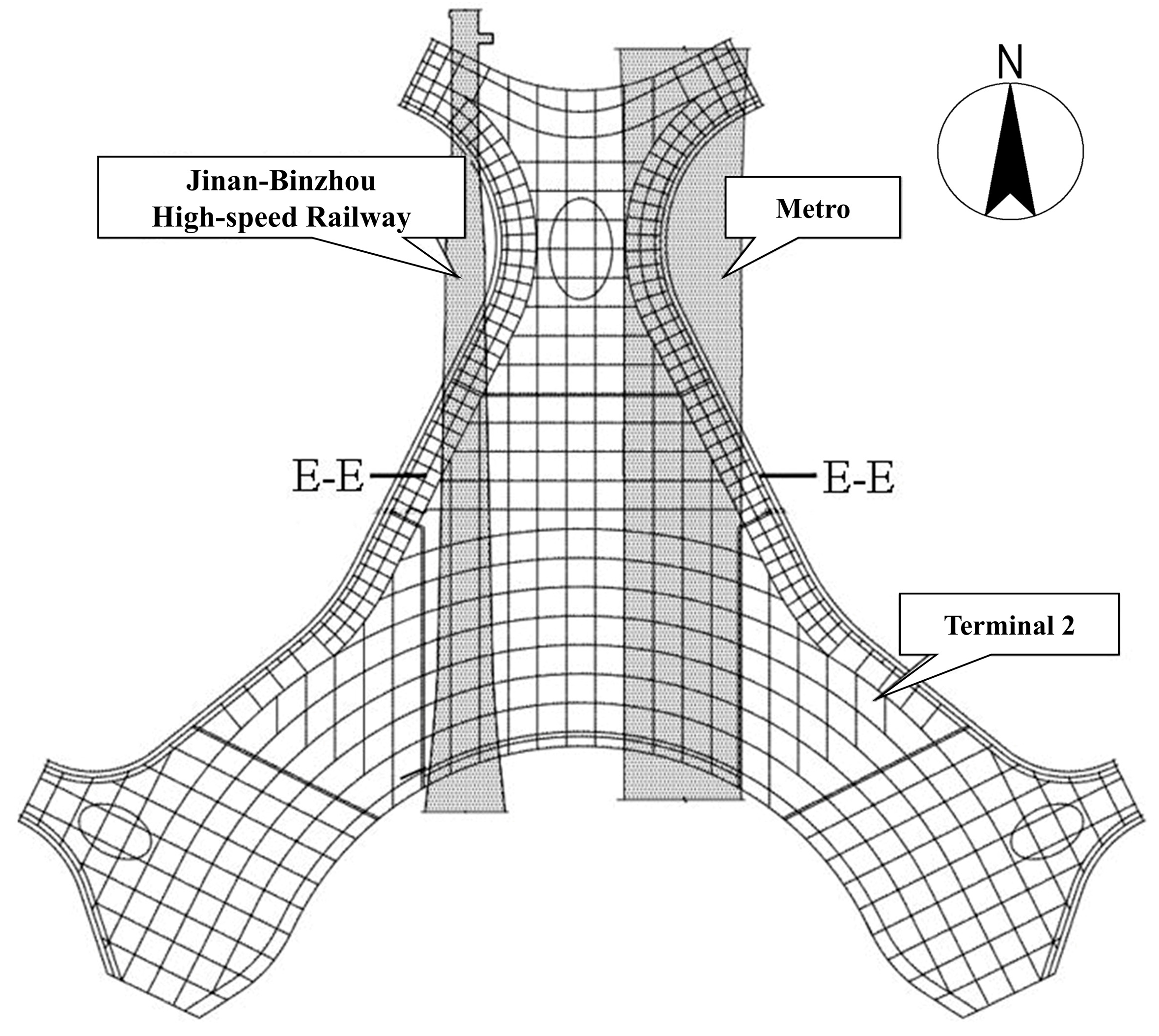
The Jinan Yaoqiang International Airport expansion project is located approximately 30 km northeast of Jinan’s city center. The key components include a 600,000 m2 T2 terminal, a Ground Transportation Center (GTC), and high-standard passenger hotel. The T2 terminal comprises three aboveground and two underground levels. Upon completion, the project will enhance the airport’s transport capacity, improve Jinan’s integrated transportation system, and promote regional economic development. The layout of the Jinan Yaoqiang Airport flight area and the T2 terminal structure is depicted in Figure 1.
The T2 terminal adopts a reinforced concrete frame structure, with floor slabs constructed as cast-in-place reinforced concrete beam-slab systems. The main structural column grid measured 9 m × 9 m, with the secondary beams arranged bidirectionally. Similarly to Beijing New Airport [18] and the New International Airport of Mexico [19], the terminal’s architectural zones vary in structural configuration, subsurface conditions, foundation types, and base elevations. The terminal’s column foundations are categorized into two sizes: large columns with a diameter of 1.4 m, bearing a maximum load of 22,500 kN at the column top, and small columns with a diameter of 0.7 m, bearing a maximum load of 2250 kN.
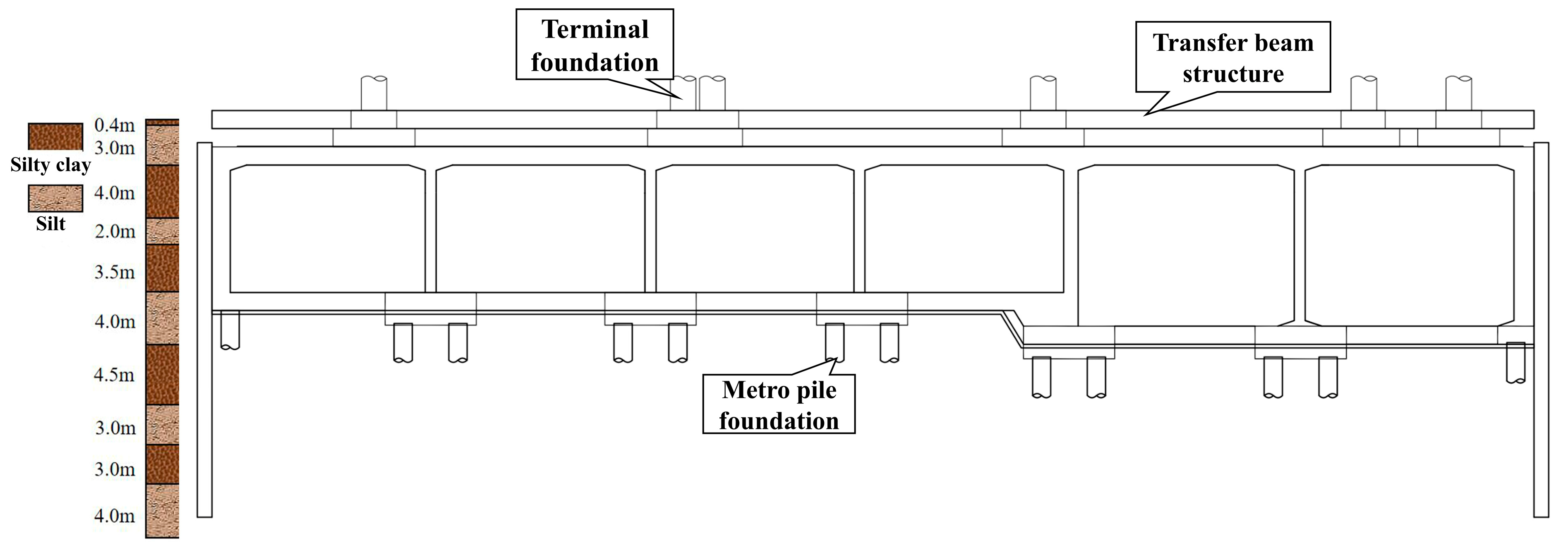
The Jinan-Binzhou High-Speed Railway and the three metro tunnels undercrossing the T2 terminal main building create complex interactions with the terminal structure. In the intercity rail transit zone, the pile cap top elevation is −9.75 m, with piles 50 m long and 1 m in diameter. In non-rail transit zones, pile cap top elevations are −5.3 m and −9.3 m in certain areas, with pile lengths of 45 m and 35 m, and corresponding pile diameters of 1 m and 0.8 m, respectively. The pile foundations beneath the high-speed railway tunnel are 30 m in length and 1 m in diameter. In contrast, the pile foundations beneath the metro tunnel are 50 m long and 1 m in diameter. The terminal connects to the high-speed rail tunnel via a transfer structure, whereas its enlarged foundation directly interfaces with the metro tunnels. Due to the large-span functional requirements of the terminal building and its overall architectural form, the structural system and column spacing of the terminal differ from those of the underlying high-speed rail and metro tunnels. The terminal loads must be transferred to the tunnel structures through a complex system of transfer structures and column foundations. In addition, the high-speed rail and metro tunnels have large spans, and their structures exhibit longitudinally varying cross-sectional forms. The terminal-tunnel interaction is illustrated in Figure 2.
In this study, cross-sections E-E of the high-speed rail and metro, which include two underground levels and are located within the T2 terminal footprint, were investigated. Figure 3 and Figure 4 show the high-speed rail and metro tunnel cross-sections, respectively.

2.2. Engineering Geology and Hydrogeology

The site lies within the geomorphic unit of the Yellow River alluvial plain. The upper strata consist of recent Yellow River floodplain deposits, which are primarily cohesive soils and silts. The lower strata comprise Quaternary Holocene alluvial soils and Upper Pleistocene alluvium, which mainly comprise cohesive soils and fine sands, with an artificial fill covering the surface. Within the exploration depth, the Quaternary strata include artificial Holocene fill, alluvial cohesive soils, silts, and fine sands. The physical and mechanical properties of each soil layer are listed in Table 1.
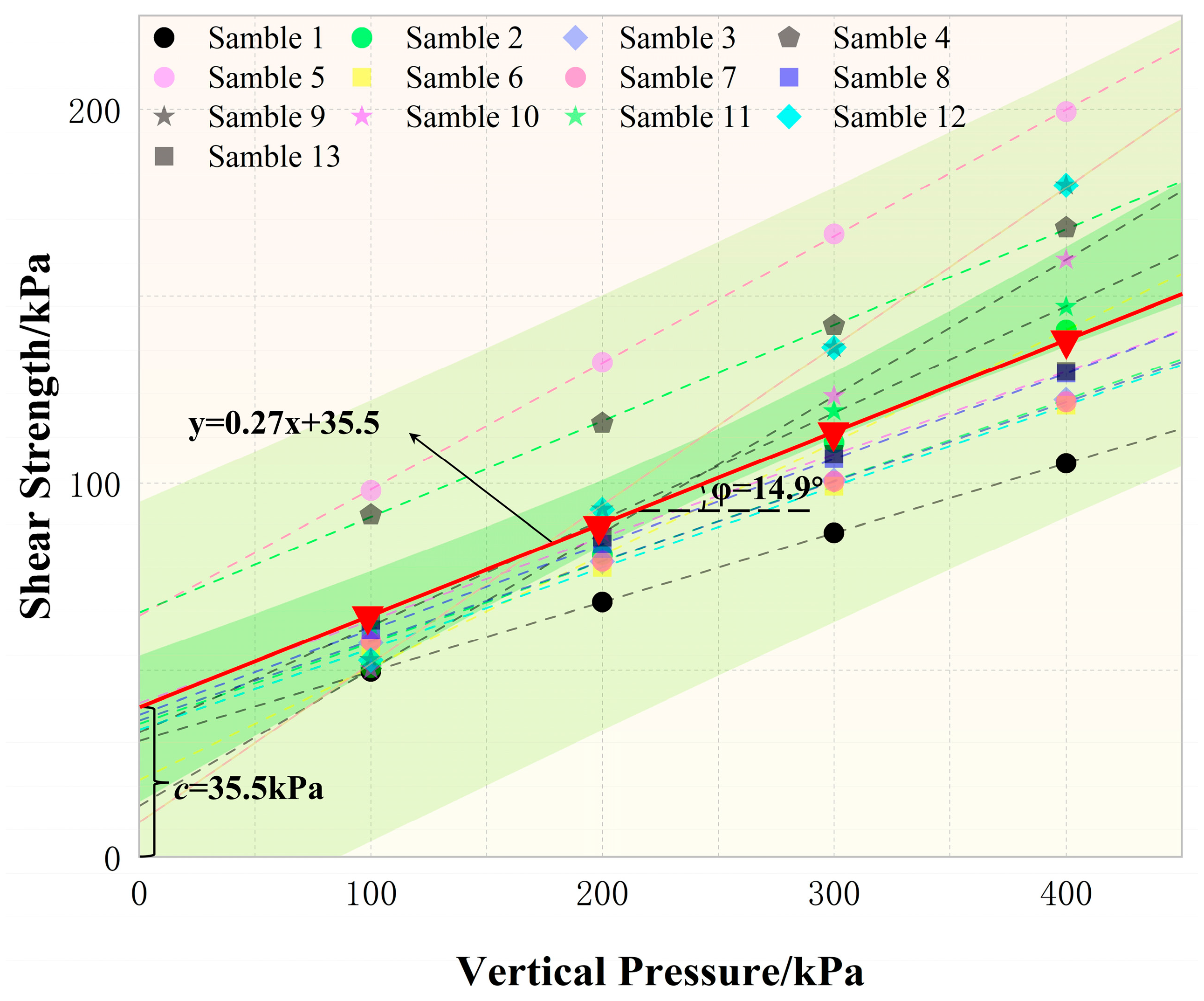
This study investigated the Mohr-Coulomb envelopes for soil specimens from Layer 11, using data from various depths as detailed in the geotechnical investigation report. These results were compiled and analyzed, and they are illustrated in Figure 5. In order to comprehensively assess the overall shear strength of the layer, a statistical analysis was performed on the cohesion (c) and friction angle (φ) values for all specimens.
Silty soils and silty clays are highly susceptible to containing expansive soils, collapsible soils, and dispersive soils, which exert significant influences on settlement [20]. Therefore, it is essential to assess the risks associated with dispersive soils in soil samples from the controlled site area. Following examination of the soil samples within the site, no expansive soils, collapsible soils, or dispersive soils were identified.
Groundwater in the study area is predominantly Quaternary pore phreatic water, which is primarily recharged by atmospheric precipitation. Consequently, water volume decreases during the dry season and increases in the rainy season, with groundwater levels ranging from 6.5 m to 7.5 m, fluctuating in response to seasonal precipitation.

3. Settlement Control Standard Analysis

3.1. Frame Structure Deformation Standards

Numerous studies have analyzed the impact of differential foundation settlement on frame structures, and representative findings are summarized in Table 2.
Meyerhof [21], Skempton and MacDonald [22], and Polshin and Tokar [23] investigated the relationship between the building load redistribution and differential settlement. Meyerhof [21] established a differential settlement limit of δ/L < 1/300. Skempton and MacDonald [22], based on field observations of 58 undamaged and 40 damaged buildings, determined a maximum allowable differential settlement limit of δ/L < 1/150. Polshin and Tokar [23] proposed a maximum allowable differential settlement of δ/L < 1/200, where δ represents differential settlement and L denotes the horizontal distance between two points. Jia et al. [24] conducted experimental studies, concluding that in frame structures, when the tangent of the beam’s rotation angle caused by column settlement is less than 1/625, crack widths remain below 0.2 mm, meeting normal structural use requirements. Hakam et al. [25] analyzed differential settlement in a reinforced concrete office building in Indonesia, determining a maximum differential settlement limit of δ/L < 1/300.
Representative standards for allowable foundation settlement in frame structures are summarized in Table 3.

3.2. Deformation Standards for Existing Tunnel Structures in Crossing Engineering

Construction projects involving new tunnels crossing existing ones pose significant deformation risks. Excavation above existing tunnels may cause uplift, while excavation below can induce settlement. Thus, the impact on existing tunnels requires thorough investigation. Multiple undercrossing project case studies were analyzed to propose clear deformation control standards for existing tunnels.
In the São Paulo Metro Line 4 undercrossing of the operational Line 2 [30], with a daily ridership of 370,000, the São Paulo Metro Company set a differential settlement standard of δ/L < 1/500 for Line 2 due to Line 4 construction. In the Shanghai Metro Line 4 undercrossing of Line 1 at Shanghai Stadium Station [31], deformation control standards required: (1) longitudinal track elevation difference <4 mm per 10 m; (2) absolute metro structure settlement ≤20 mm. For Shanghai Metro Line 8 crossing above Line 2 between Qufu Road and People’s Square [32], using earth pressure balance shield tunneling, the deformation control standards for operational Line 2 structures were set at ±5 mm for longitudinal settlement and uplift and ±5 mm for longitudinal horizontal displacement. In the Shenzhen Metro Line 2 undercrossing of Line 1’s double-layer tunnel at Shennan Middle Road [33], with a 55° intersection angle, settlement control standards limited maximum settlement and horizontal displacement to ≤20 mm, with a longitudinal deformation curve radius ≥15,000 m and a slope ≤1/2500. The Shenzhen Metro Line 2 tunnel section from Yannan Station to Grand Theater Station undercrossing Line 1’s Science Museum to Grand Theater section [34], constructed using the mining method, set a settlement standard of ≤20 mm. In the Changsha Metro Line 1 tunnel section from Tuqiao Station to Central South University Station [35], using shield tunneling and undercrossing the Beijing-Guangzhou Railway, standards specified settlement ≤30 mm and uplift ≤20 mm. The Beijing Airport Express Dongzhimen Station Tunnel Section C crossing Metro Line 13’s Dongzhimen Station return line [36] was required to existing tunnel settlement within 15 mm. During the construction of the Yujingshan Tunnel, a large karst cavity was encountered [37]. A comprehensive construction scheme combining an ultra-thick backfill and a continuous rigid-frame bridge was adopted. Based on this, the maximum permissible long-term settlement of the tunnel was proposed as 40 mm, with a maximum allowable differential settlement of 10 mm. In the Chongqing Central Business District, a 2580 m underground ring tunnel was constructed, consisting of a main tunnel and five branch tunnels [38]. The construction adopted the CRD (Cross-Diagram) method, with the proposed allowable deformation limits of 3–10 mm for tunnel structural settlement and 20 mm for the foundation settlement of overlying buildings. For Changzhou Metro Line 2, which intersects the Beijing–Shanghai High-Speed Railway, construction measures were formulated considering the operational safety of the railway [39]. The maximum settlement of the high-speed railway was restricted to 10 mm, and the maximum differential settlement within a 10 m span was limited to 5 mm.
In urban rail transit tunnel construction, projects involving undercrossing or overcrossing of existing tunnels typically establish settlement control standards. Common indicators include settlement limits of ≤20 mm to 30 mm, track elevation differences <4 mm/10 m, and stricter projects set longitudinal displacement and uplift limits at ±5 mm.

3.3. Deformation Standards of High-Speed Railway and Metro Structures After Construction

According to the Chinese code “Code for Monitoring Measurement of Urban Rail Transit Engineering” (GB 50911-2013) [40], the cumulative settlement limit for existing urban rail transit tunnel structures ranges from 3 mm to 10 mm, while the allowable differential settlement is defined as 0.04% Ls (Ls represents the axial spacing between two monitoring points along the tunnel).
Another Chinese code “Technical Specification for Safety Protection of Urban Rail Transit Structures” (CJJ/T 202-2013) [41], explicitly defines safety control criteria for urban rail transit structures. The early warning thresholds for the horizontal displacement, vertical displacement, and radial convergence of tunnel structures should be less than 10 mm, with control limits of less than 20 mm. Additionally, early warning values for transverse track irregularity and track alignment deviations should not exceed 2 mm, with control limits under 4 mm.
Silot Soeung et al. [42] analyzed the causes of settlement in high-speed railway structures in Korea and reviewed the track settlement criteria of German and Japanese high-speed railways. German standards permit a maximum settlement of 30 mm, whereas Japan restricts the settlement to less than 10 mm over a ten-year period, with an absolute maximum settlement not exceeding 30 mm.
According to existing engineering practices and relevant research findings, explicit settlement control standards for integrated constructions involving buildings structures and tunnel structures are currently unavailable. During joint construction, the differential settlements of the upper structural foundations, directly affects the overall and differential settlement of the undercrossing tunnel structures. To ensure structural safety during construction, this study adopts the strictest differential settlement limitation among existing research results, setting δ/L < 1/625 as the tangent rotation angle criterion caused by differential settlement between adjacent column foundations of the frame structure. Based on this rotation angle limitation of the adjacent terminal column foundations, predictions were made for the maximum allowable settlement and differential settlement of the undercrossing tunnel structures.

4. Analysis of Settlement Characteristics of Underground Structures Subjected to Uneven Loading from Terminal Buildings

4.1. Numerical Model

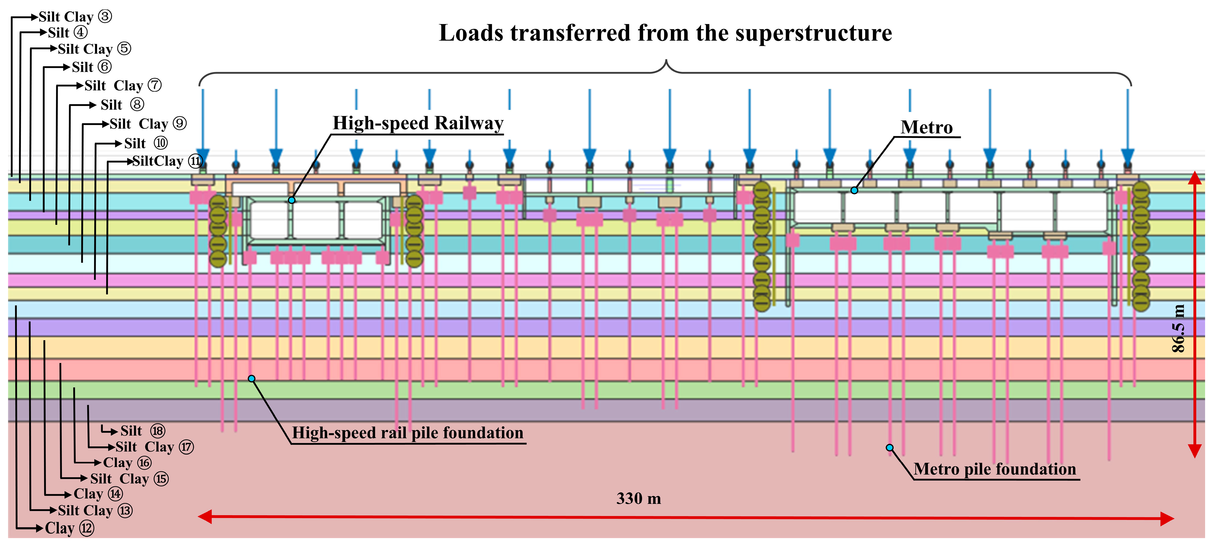
To investigate the settlement patterns of large-section underground structures subjected to uneven loads from terminal buildings, the finite element software PLAXIS version 2020 was employed to simulate the effects of these loads on the tunnel structure at cross-section E-E. The finite element model, with dimensions of 330 m × 86.5 m, was designed to mitigate the boundary effects. The influence of groundwater was not considered in the simulation. The cross-sectional finite element model of the high-speed railway and metro structures at Section E-E is shown Figure 6.
In this study, the soil was modeled using a two-dimensional plane strain triangular element with 15 displacement nodes. The 15-node triangular element provides a fourth-order displacement interpolation, and numerical integration is performed at 12 stress points. The locations of the mesh nodes and stress points of the 15-node triangular element are shown in Figure 7.

4.2. Constitutive Model and Parameters

The Hardening Soil (HS) constitutive model was adopted for the soil layers. According to existing research [43,44,45], typical empirical deformation parameters for soils in the HS model were selected as follows: 3 E oed ref = 3 E 50 ref = E ur ref , E oed ref = 3Es. The structural components were simulated using a linear elastic model. Tunnel structures and other related components were modeled using plane strain elements. The nonlinear behavior of piles is critical to accurately capture their complete load-settlement response [46]. In practical engineering, the loading process of a pile foundation involves not only the elasto-plastic characteristics of the pile shaft material but also the nonlinear evolution of pile-soil interface friction and end bearing resistance. To simulate this, the pile body is modeled with embedded pile elements, which define the pile’s axial skin friction and end bearing resistance to reproduce the slip and overall bearing capacity of the pile-soil interface. The elastic modulus E of tunnel structures and piles was set at 32.5 GPa, with Poisson’s ratio ν = 0.2. Interface elements, with a strength reduction factor of 0.7, were used to represent interactions between tunnel retaining structures and surrounding soils. The equivalent bending and axial stiffnesses were considered for transfer structures, pile caps, and terminal column foundations. The loads from terminal structures were equivalently reduced. Table 4 summarizes the calculation parameters.

4.3. Simulation of Construction Process

To realistically model settlement behaviors of high-speed railway and metro structures subjected to uneven loading from terminal buildings, an element activation-deactivation approach was employed in the finite element software. Initially, the ground stress state was balanced. Subsequently, diaphragm walls were constructed, foundation pits were excavated, and the lower structures of high-speed railway and metro tunnels, along with piles beneath the terminal, were installed. In the third step, structural elements including tunnels, transfer structures, and terminal column foundations were activated. Finally, uneven loads were applied to the tops of the terminal column foundations to simulate the full construction sequence and loading process associated with the coexistence of tunnel and terminal structures.
During the model computation, the feedback information provided in the PLAXIS 2D calculation log was used as the basis for assessing model convergence. For the four calculation stages defined in this study, we examined the corresponding log data of each stage. The results indicated that the convergence criteria were satisfied in all cases. Taken together, these verification results demonstrate that the numerical model developed in this study exhibits overall good convergence performance.

5. Results and Discussion

5.1. Settlement Behaviors of Terminal Slabs and Column Foundations

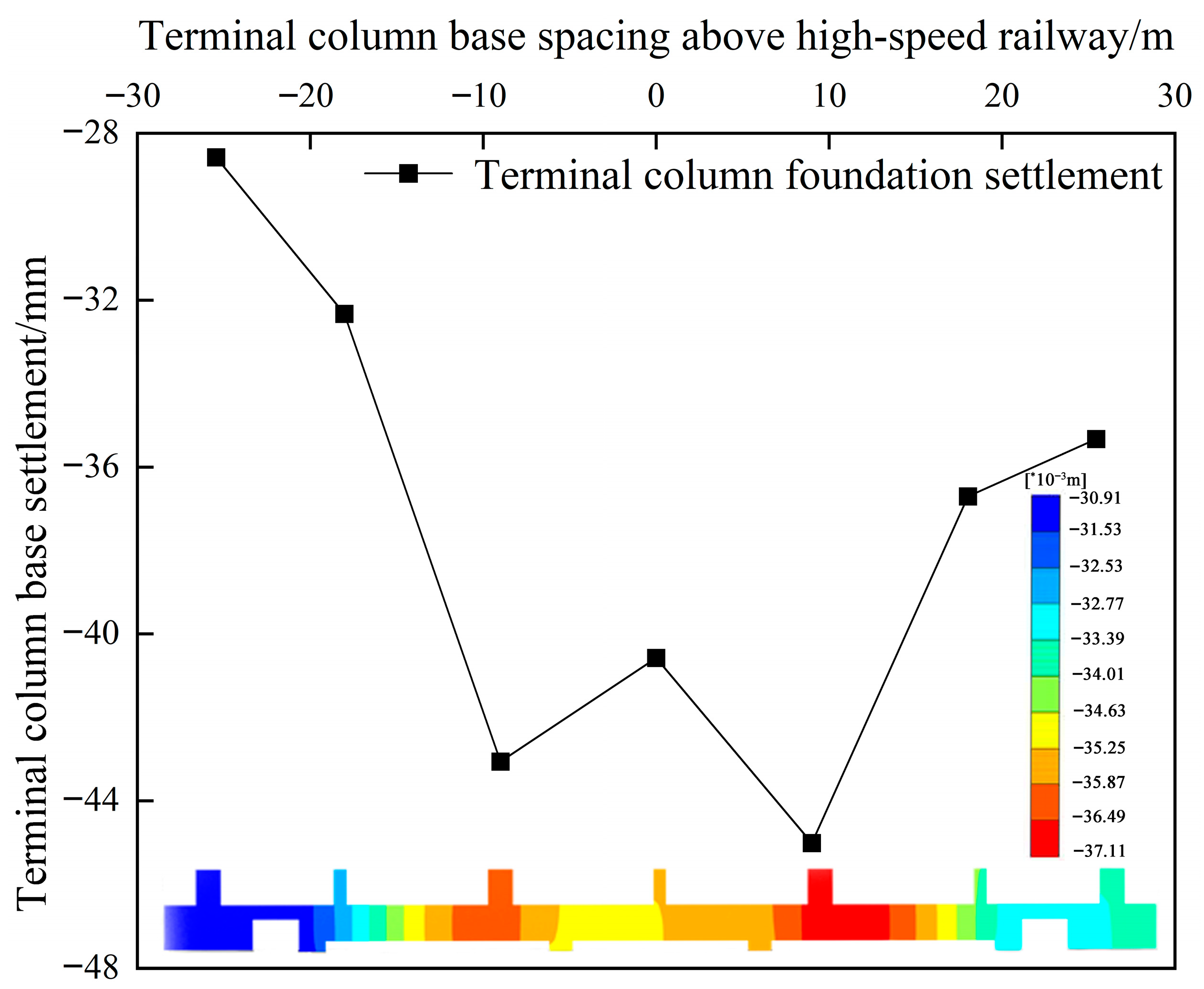
Figure 8 presents the settlement contour of the E-E cross-section. The terminal slab exhibited greater settlement above the high-speed railway structure than above the metro structure. The maximum settlement, observed beneath the adjacent column foundations over the left-span transfer structure of the high-speed railway, was 45.45 mm.
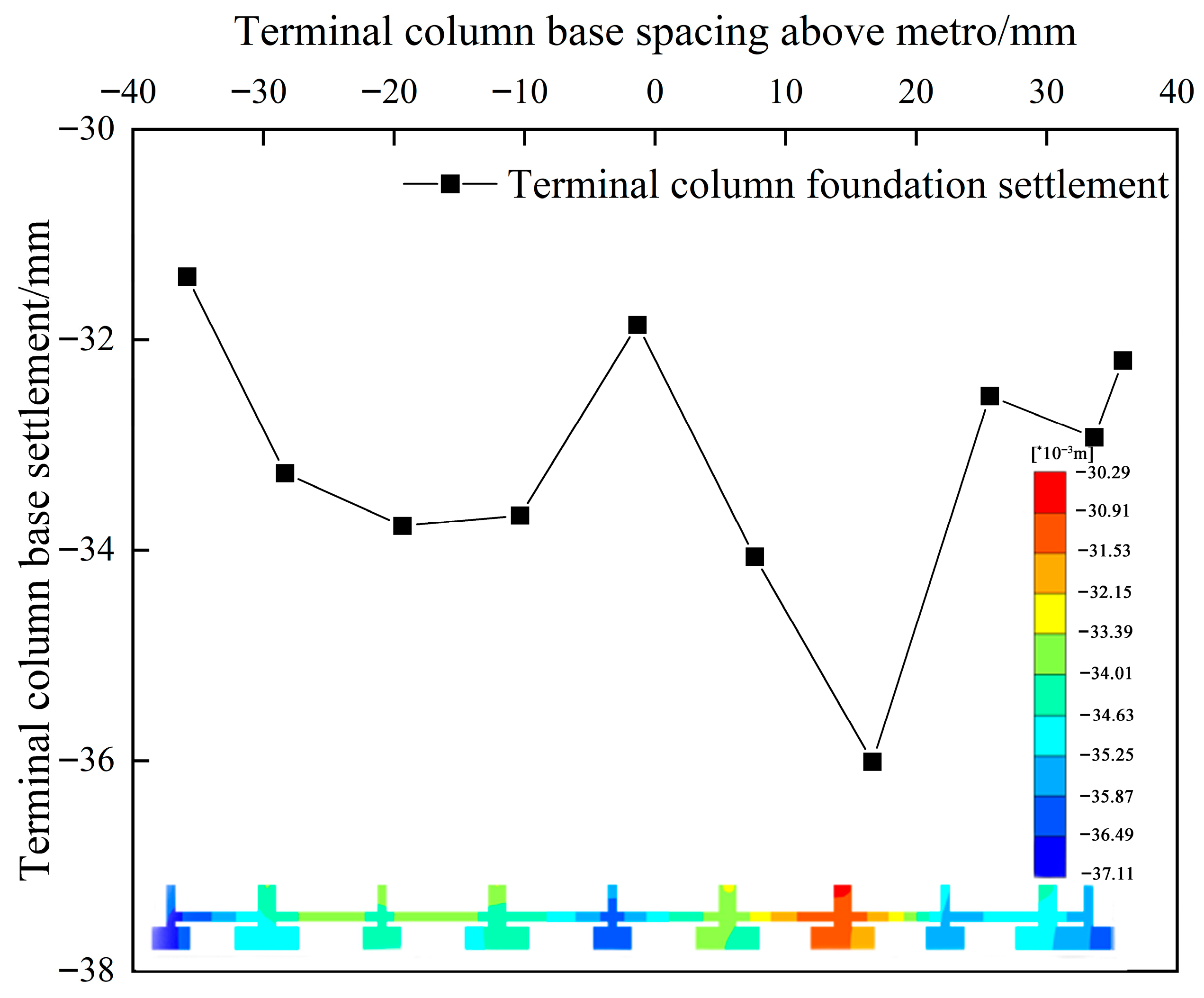
The settlement curves of column foundations for terminal structures above the high-speed railway and metro tunnels at cross-section E-E are provided in Figure 9 and Figure 10. The maximum differential settlement between the adjacent terminal column foundations above the high-speed railway was 10.73 mm, located at the adjacent columns above the left-span transfer structure, corresponding to a rotation angle tangent of 1/839. On the metro side, the column foundations on the left experienced relatively larger settlements owing to the influence of the column foundations from adjacent non-rail transit regions. However, the right-side columns above the metro tunnel exhibited the greatest settlement, owing to the concentration and magnitude of terminal loads. The maximum differential settlement between adjacent metro-side columns was 3.48 mm, corresponding to a rotation angle tangent of 1/2299.

5.2. Settlement Behaviors of High-Speed Railway Structure

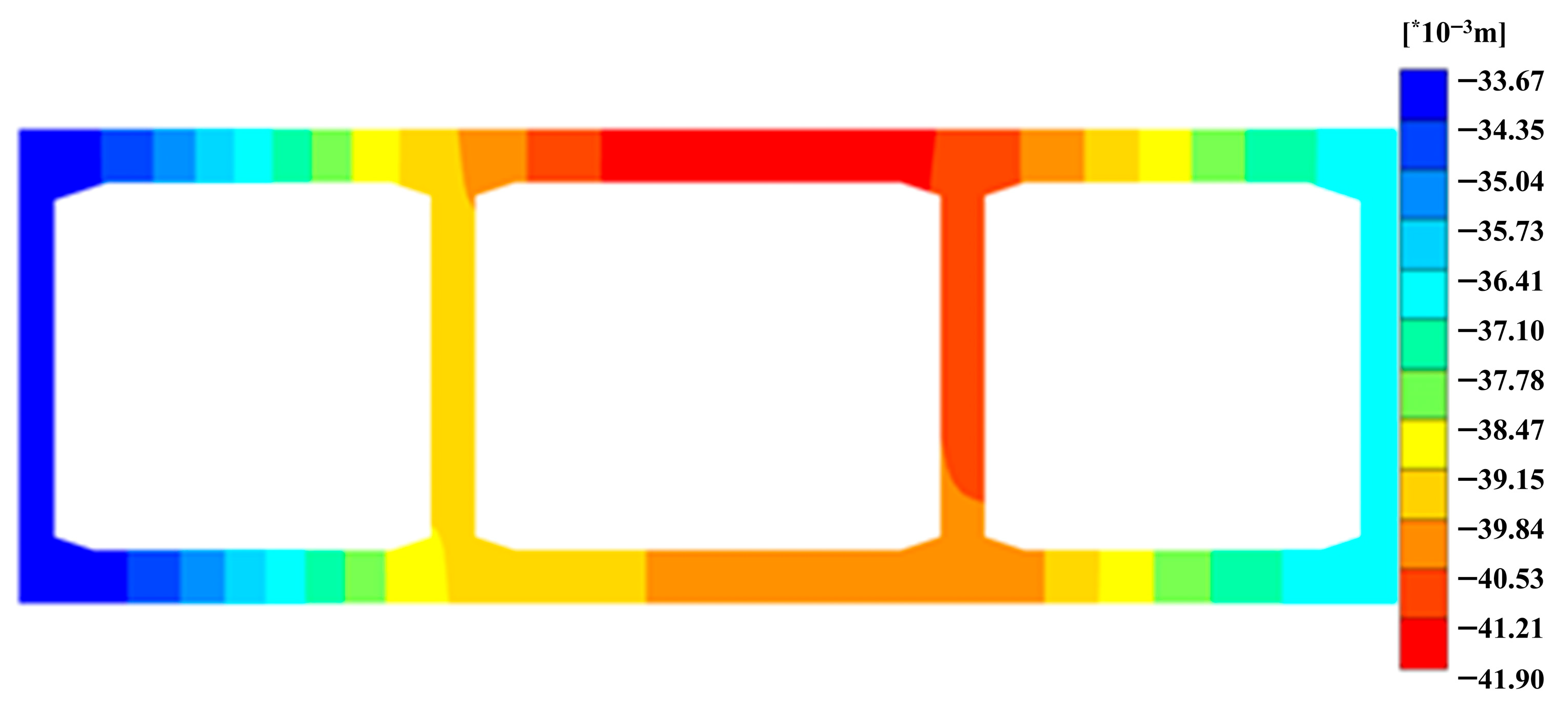
Figure 11 presents the settlement contour of the high-speed railway tunnel at cross-section E-E. It is evident that the middle tunnel exhibits greater settlement than the tunnels on both sides. The positions of maximum settlement for the roof and floor slabs of the tunnel structure are roughly consistent, with the maximum roof slab settlement slightly offset to the right from the centerline, and the maximum floor slab settlement occurring beneath the right central partition wall.
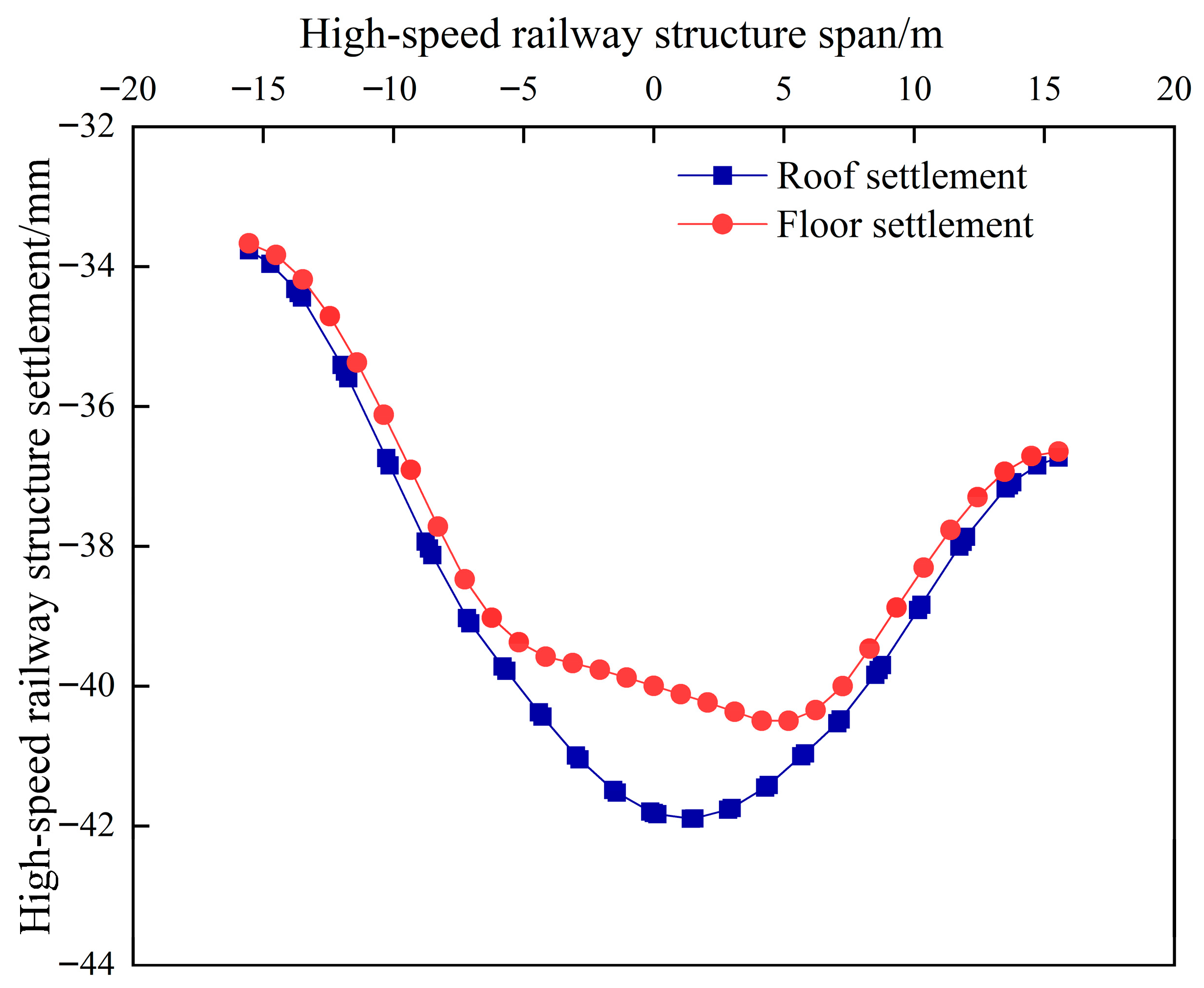
The settlement curves for the high-speed railway structure at cross-section E-E are shown in Figure 12. The maximum settlement values for the roof and floor slabs are 41.9 mm and 40.5 mm, respectively. The differential settlements between the side walls and adjacent central partition walls are 5.49 mm and 3.78 mm, corresponding to tangent rotation angles of 1/1712 and 1/2487, respectively. The differential settlement between the left and right central partition walls is 1.23 mm, corresponding to a tangential rotation angle of 1/9350.

5.3. Settlement Behaviors of Metro Structure

Figure 13 shows the settlement contour of the metro structure at cross-section E-E. The settlement of metro structure is significantly affected by the positions and magnitudes of the loads from the column foundations of the overlying terminal building. The maximum settlement of the metro roof slab was 36.73 mm, located beneath the third column row from the right, where the load concentration and magnitudes were notably high. The maximum settlement of the metro floor slab was 33.05 mm, located beneath the left partition wall of the second tunnel chamber from the right.
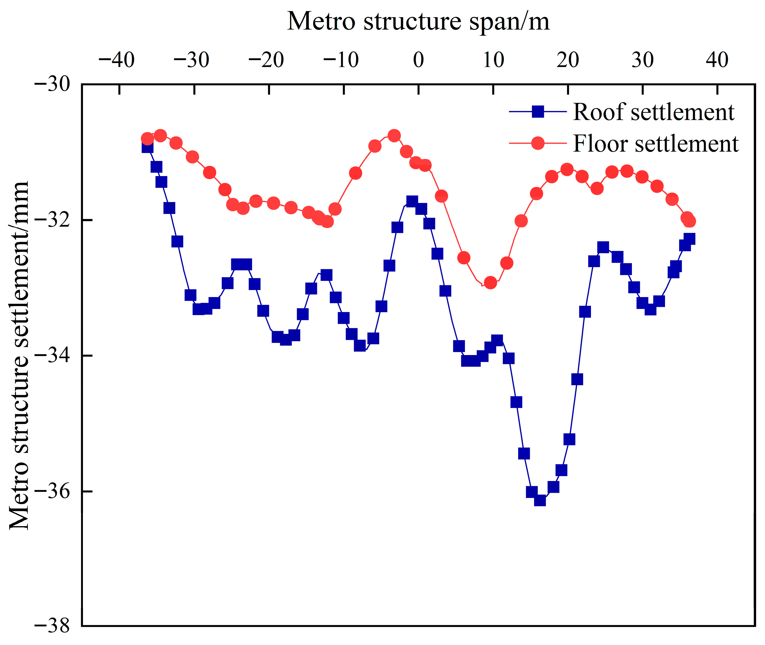
The settlement curves of the metro structure at cross-section E-E are presented in Figure 14. The settlement trends of the roof and floor slabs were similar, with maximum roof slab settlements occurring at the center of each tunnel chamber, and maximum floor slab settlements beneath the internal partition walls. The maximum differential settlement between adjacent partition walls of the metro structure was 1.76 mm, with a corresponding tangent rotation angle of 1/6591.

5.4. Sensitivity Analysis of Model Boundary Dimensions

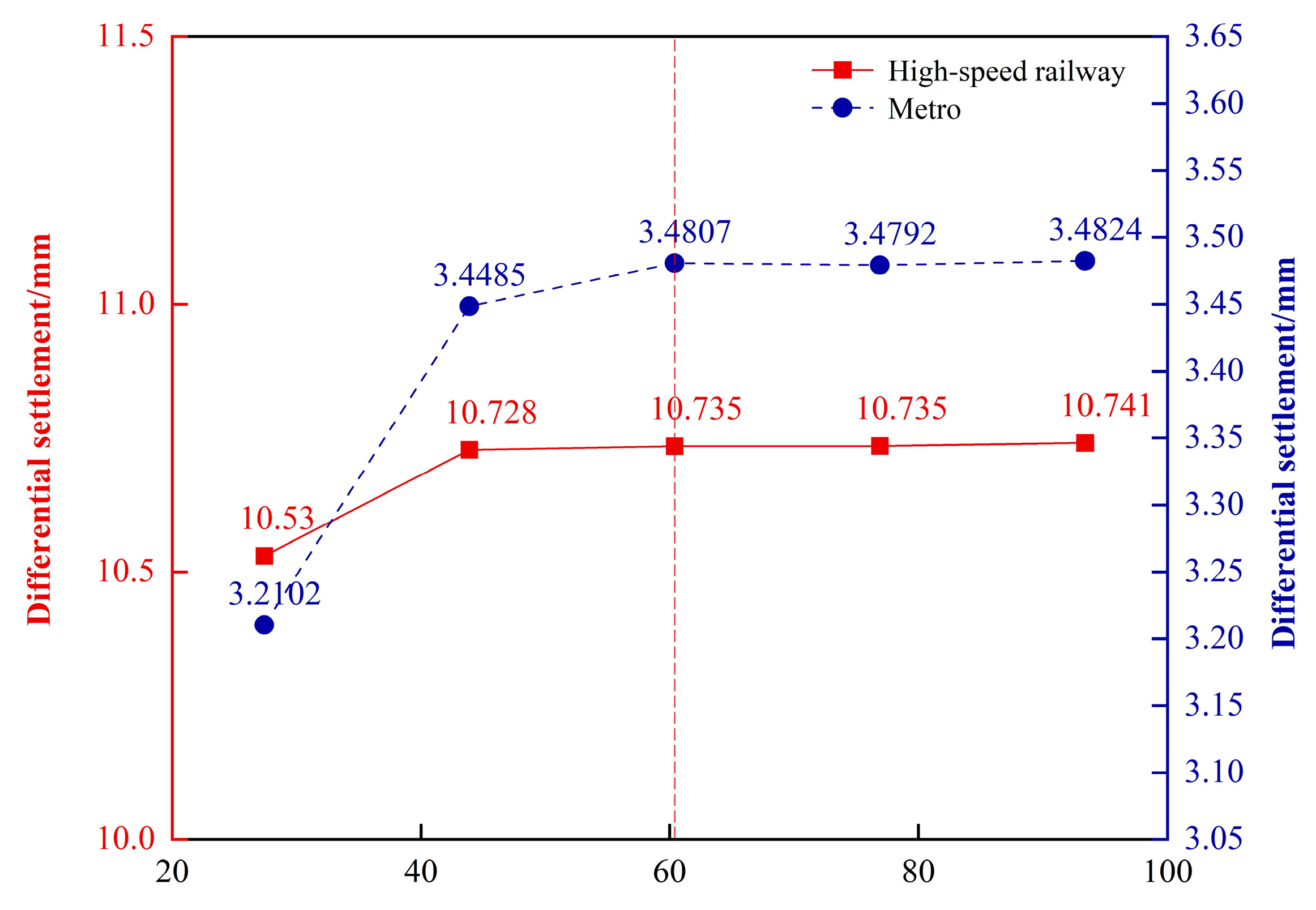
In numerical simulation software such as PLAXIS 2D, the setting of certain parameters can significantly influence the computational results. Therefore, sensitivity analysis of model parameters is essential in related studies. To eliminate the potential interference of boundary dimensions on the conclusions of this research, four groups of models with different boundary conditions were established for comparative analysis.
In this study, the horizontal distance from the model boundary to the structural boundary was set to 60.4 m. A variation gradient of 5% of the horizontal dimension (i.e., 16.5 m) was applied, resulting in four additional boundary dimensions of 27.4 m, 43.9 m, 76.9 m, and 93.4 m. The maximum differential settlement between adjacent high-speed rail and metro column foundations was selected as the comparative indicator. As shown in Figure 15, it is evident that with increasing model boundary dimensions, the maximum differential settlement between adjacent column foundations of the high-speed rail and metro gradually stabilizes. This indicates that the boundary dimensions adopted in this study adequately satisfy the sensitivity requirements of the numerical analysis.
In light of the above settlement results, it is recommended that, during practical construction, reinforcement measures such as increasing the concrete strength grade be applied to the right-side transfer structure above the metro and to the transfer structure above the high-speed rail. These measures would enhance the structural deformation resistance and reduce the differential settlement of the terminal building superstructure above the section. Since the settlement of the high-speed rail tunnel roof is greater than that of the floor, a geometric optimization measure, such as increasing the thickness of the tunnel roof slab, may be adopted at the design stage to mitigate roof settlement. Given that stability issues are common in complex underground structures [47], numerous scholars in recent years have employed settlement monitoring and early-warning methods for their assessment [48,49]. In subsequent engineering practice, it is essential to further strengthen on-site settlement monitoring in order to promptly detect significant deformations and prevent structural damage or failure.
In recent years, machine learning techniques have achieved notable progress in the field of numerical modeling, particularly in multi-parameter sensitivity analysis. Such approaches can efficiently address the coupling of high-dimensional parameters and significantly reduce reliance on traditional computation-intensive modeling. For example, Vahid Jahangiri et al. [50] explored the application of machine learning to predict the maximum inter-story drift ratio of steel structural systems, thereby substantially decreasing the dependence on intensive numerical simulations. In our future work, we plan to integrate machine learning methods into the systematic sensitivity analysis of multi-key parameters in the numerical models of co-construction projects. This will enable the identification of dominant factors governing settlement and provide more targeted guidance for the optimization of design and settlement control in integrated terminal–tunnel structures.

6. Prediction and Analysis of Co-Construction Structure Settlement

Through numerical simulations, the settlements and tangent rotation angles for the base slabs at cross-section E-E are summarized in Table 5. All the tangent rotation angles between the adjacent terminal building column foundations remained below 1/625, satisfying the serviceability the requirements for the terminal structure.
Based on the established settlement control standard for the terminal building and the numerical results, a tangent rotation angle of 1/625 between adjacent column foundations was set as the allowable limit. The allowable differential settlements for the terminal foundations and the corresponding maximum allowable settlements and differential settlements for high-speed railway and metro structures were predicted by adjusting the terminal load amplification factor. The amplification factor for uneven terminal loads was varied between 1.0 and 2.0. A nonlinear regression analysis was employed for precise settlement predictions owing to the nonlinear characteristics of the differential settlement curves.
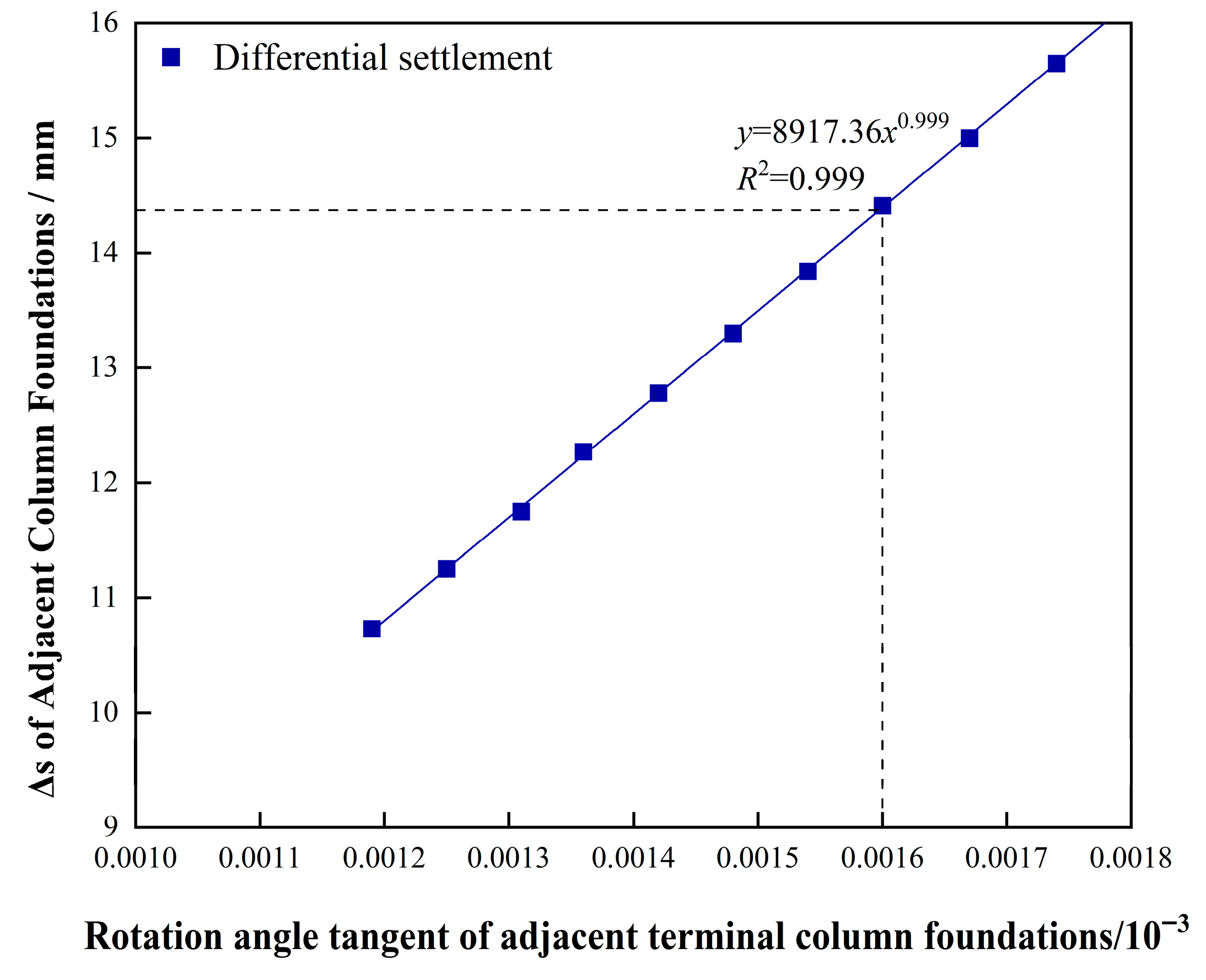
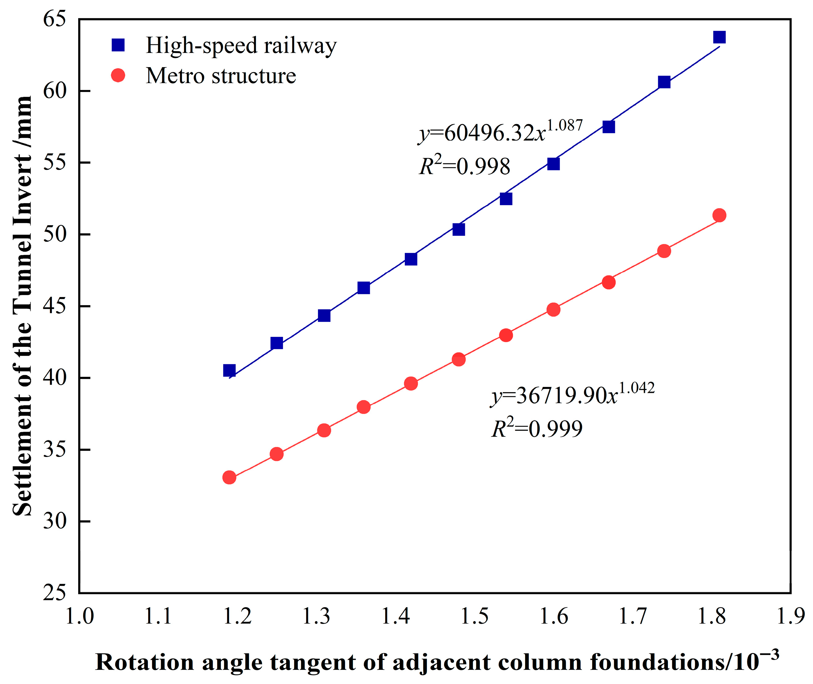
Figure 16 shows the predicted maximum differential settlement curve for the adjacent terminal column foundations at cross-section E-E. When the tangent rotation angle reached the limit of 1/625, the permissible maximum differential settlement between adjacent terminal foundations was approximately 14.37 mm. The predicted maximum settlements for the base slabs of the high-speed railway and metro structures at cross-section E-E are shown in Figure 17. At the rotation angle limit of 1/625, the allowable maximum settlements are 55.28 mm for the high-speed railway base slab and 44.83 mm for the metro base slab. Figure 18 illustrates the predicted maximum differential settlement curves for the base slabs of the high-speed railway and metro structures at cross-section E-E. At a rotation angle limit of 1/625, the maximum allowable differential settlements are 7.5 mm for the high-speed railway and 3.13 mm for the metro structure.

7. Conclusions

Based on the case study of a large-section underground structure integrated with the airport terminal, settlement control standards for the terminal building were established. Through numerical simulations, the maximum permissible differential settlement for adjacent terminal foundations and the allowable maximum settlement and differential settlement limits for high-speed railway and metro structures were predicted. The conclusions are as follows:
  • A settlement control criterion for the adjacent column foundations of the terminal structure, defined by a rotation angle tangent of 1/625, was established to ensure normal serviceability by controlling the differential settlements of the column foundations.
  • At cross-section E-E, the maximum differential settlement and tangent rotation angle for the adjacent terminal column foundations occurred at the columns above the left span of the transfer structure, with a differential settlement of 10.73 mm and a rotation angle tangent of 1/839.
  • The settlements of the high-speed railway and metro tunnel slabs were lower at mid-span locations and higher at the internal partition walls. The maximum differential settlements between adjacent partition walls at cross-section E-E are 5.49 mm for the high-speed railway and 1.76 mm for the metro structure, corresponding to rotation angle tangent of 1/1712 and 1/6591, respectively.
  • When the rotation angle tangent between adjacent terminal column foundations reaches the specified limit of 1/625, the allowable maximum differential settlement for adjacent terminal foundations at cross-section E-E is approximately 14.37 mm. Under these conditions, the maximum allowable settlements of the base slabs for the high-speed railway and metro structures at cross-section E-E are limited to 55.28 mm and 44.83 mm, respectively, with corresponding allowable differential settlements limited to 7.5 mm and 3.13 mm.
The interface relationship between the terminal building and the high-speed rail/metro hub is highly complex. For future newly built airports and other large-scale transportation hubs, adopting an integrated design approach that coordinates both transportation alignment and architectural layout can help avoid conflicts between routes and buildings, as well as structural deformation issues, thereby optimizing the rationality of engineering design.

Author Contributions

Conceptualization, S.L.; methodology, R.Z., G.S., S.L.; validation, W.L., Z.W.; formal analysis, R.Z., Z.W., J.H., G.S.; investigation, R.Z., Z.W., J.H., G.S.; resources, W.L.; data curation, J.H.; writing—original draft preparation, R.Z.; writing—review and editing, Z.W., S.L.; visualization, J.H.; supervision, W.L.; project administration, W.L.; funding acquisition, G.S. All authors have read and agreed to the published version of the manuscript.

Funding

This research was funded by the Key Research and Development Program of Gansu Province, China (Grant No. 22YF7FH224), Shandong Youth Innovation Team (No. 2023KJ324), Open Program of Engineering Research Center of Concrete Technology under Marine Environment, Ministry of Education (Grant No. 2024KFKTYB12), and the Doctoral Research Fund of Shandong Jianzhu University (Grant No. X19080Z).

Data Availability Statement

The datasets used or generated during the current study are available from the corresponding author upon reasonable request.

Acknowledgments

We would like to express our gratitude to the Key Research and Development Program of Gansu Province, China (Grant No. 22YF7FH224), Shandong Youth Innovation Team (No. 2023KJ324), Open Program of Engineering Research Center of Concrete Technology under Marine Environment, Ministry of Education (Grant No. 2024KFKTYB12), and the Doctoral Research Fund of Shandong Jianzhu University (Grant No. X19080Z) for their support of this study. We deeply appreciate the warm and efficient effort of editors and reviewers.

Conflicts of Interest

Author Wei Liu and Zekun Wei are employed by the China Railway No. 10 Engineering Group Urban Construction Co., Ltd. The remaining authors declare that the research was conducted in the absence of any commercial or financial relationships that could be construed as a potential conflict of interest.

References

  1. Luo, Q.Y.; Jia, H.F.; Sun, B.F. Research on evaluating functions and structures of comprehensive passenger transport hub. In Proceedings of the 1st International Conference on Sustainable Construction & Risk Management, Beijing, China, 16–18 October 2010; Wu, D., Xu, M.Z., Zhang, Z.J., Fang, Y., Eds.; China Architecture & Building Press: Beijing, China, 2010; pp. 184–188. [Google Scholar]
  2. Yatskiv, I.; Budilovich, E. A comprehensive analysis of the planned multimodal public transportation HUB. Transp. Res. Procedia 2017, 24, 50–57. [Google Scholar] [CrossRef]
  3. Pshinko, O.; Charkina, T.; Martseniuk, L.; Orlovska, O. Hubs as a key tool for improving the quality of the service and development of multimodal passenger traffic. Transp. Probl. 2022, 17, 201–214. [Google Scholar] [CrossRef]
  4. Jia, J.; Fang, Y.G. Underground space development in comprehensive transport hubs in China. In Underground Urbanisation as a Prerequisite for Sustainable Development, Proceedings of the 15th World Conference of the Associated Research Centers for the Urban Underground Space (ACUUS), Saint Petersburg, Russia, 12–15 September 2016; Alpatov, S., Prentkovskis, O., Sterling, R.L., Kaliampakos, D., Eds.; Elsevier: Amsterdam, The Netherlands, 2016; Volume 165, pp. 404–417. [Google Scholar]
  5. Sun, X.; Zheng, C.; Li, J.; Jiang, C.; Zhang, A.; Wandelt, S. A review on research regarding HSR interactions with air transport and outlook for future research challenges. Transp. Policy 2024, 157, 74–85. [Google Scholar] [CrossRef]
  6. Huan, N.; Yamamoto, T.; Yao, E. Seamless air-HSR intermodal solution: Behavioural model-based scheduling of airline timetable and airfare. Transp. Res. Part A Policy Pract. 2023, 176, 103821. [Google Scholar] [CrossRef]
  7. Zang, Y.W.; Liu, C.B.; Yan, J.J.; Yu, J.L.; Yu, T.C.; Zhu, H.D.; Ding, P.; Zhu, J.C.; Xu, R.Q. Study on the Influence and Control Methods of Shield Tunneling through the Sensitive Buildings. In Proceedings of the 8th International Conference on Hydraulic and Civil Engineering—Deep Space Intelligent Development and Utilization Forum (ICHCE), Xi’an, China, 25–27 November 2022; IEEE: Piscataway, NJ, USA, 2022; pp. 311–316. [Google Scholar]
  8. Liu, Y.; Zhou, Y.; Suo, X.; Fan, H.; Cao, Y.; Du, Z. Model test on the deformation law of shield tunnel underpassing high speed railway roadbed. Yantu Lixue Rock Soil Mech. 2023, 44, 941–951. [Google Scholar] [CrossRef]
  9. Zhang, X.; Tan, H.; Liu, Z.; Dong, J.; Liu, S. Study on the Influence of Subway Tunnel Induced by Under-Crossing Tunnel Based on Monitor Data in Shenzhen, China. Sustainability 2023, 15, 13232. [Google Scholar] [CrossRef]
  10. Ding, Z.; Wei, X.J.; Wei, G. Prediction methods on tunnel-excavation induced surface settlement around adjacent building. Geomech. Eng. 2017, 12, 185–195. [Google Scholar] [CrossRef]
  11. Gong, C.J.; Xie, C.R.; Lin, Z.Q.; Xie, D.W.; Zhou, Z. Ground deformation prediction induced by shield tunnelling considering existing multi-story buildings. J. Cent. South Univ. 2023, 30, 1373–1387. [Google Scholar] [CrossRef]
  12. Ma, B.L.; Wu, S.Z.; Chen, Q.H.; Liang, E.B.; Li, X.D. The influence of existing piles on station settlement during the construction of a tunnel undercrossing under existing stations. Sci. Rep. 2024, 14, 14024. [Google Scholar] [CrossRef] [PubMed]
  13. Zheng, Y.; Wu, K.; Sun, J.; Chen, R.; Li, Y.; Yang, S. Study on the Influence of Close Distance Construction of Urban Tunnel on the Existing Station. Geotech. Geol. Eng. 2021, 39, 4765–4780. [Google Scholar] [CrossRef]
  14. Nematollahi, M.; Dias, D. Interaction between an underground parking and twin tunnels—Case of the Shiraz subway line. Tunn. Undergr. Space Technol. 2020, 95, 103150. [Google Scholar] [CrossRef]
  15. Zhang, M. Options selection and impact study of intercity railway tunnel construction under airport interzone. Stavební Obz.-Civ. Eng. J. 2024, 33, 275–293. [Google Scholar] [CrossRef]
  16. Williams, I. Heathrow terminal 5: Tunnelled underground infrastructure. Proc. Inst. Civ. Eng. Civ. Eng. 2008, 161, 30–37. [Google Scholar] [CrossRef]
  17. Li, X.; Yuan, D.; Jin, D.; Yu, J.; Li, M. Twin neighboring tunnel construction under an operating airport runway. Tunn. Undergr. Space Technol. 2018, 81, 534–546. [Google Scholar] [CrossRef]
  18. Fang, Y.; Wang, Y.; Lu, P. New Airport Design and verification of pile foundation of Terminal Area of Beijing. Build. Struct. 2017, 47, 21–25. [Google Scholar] [CrossRef]
  19. Clark, M.; Pe, C.M. Challenges of design and construction of passenger terminal building foundation, New International Airport of Mexico, Mexico City. In Proceedings of the 17th European Conference on Soil Mechanics and Geotechnical Engineering, ECSMGE 2019—Proceedings, Reykjavík, Iceland, 1–6 September 2019. [Google Scholar]
  20. Asadoullahtabar, S.R.; Asgari, A.; Tabari, M.M.R. Assessment, identifying, and presenting a plan for the stabilization of loessic soils exposed to scouring in the path of gas pipelines, case study: Maraveh-Tappeh city. Eng. Geol. 2024, 342, 107747. [Google Scholar] [CrossRef]
  21. Meyerhof, G.G. The settlement analysis of building frames. Struct. Eng. 1947, 25, 369–409. [Google Scholar]
  22. Aw, S.; Dh, M. The allowable settlement of buildings. Proc. Inst. Civ. Eng. 1956, 5, 727–784. [Google Scholar]
  23. Polshin, D.E.; Tokar, R.A. Maximum allowable non-uniform settlement of structures. In Proceedings of the Fourth International Conference on Soil Mechanics and Foundation Engineering, London, UK, 12–14 August 1957; pp. 402–405. [Google Scholar]
  24. Jia, Q.; Cheng, L.; Zhang, X. Experimental study of the influence of differential settlement on RCframe structures. China Civ. Eng. J. 2011, 44, 79–86. (In Chinese) [Google Scholar] [CrossRef]
  25. Hakam, A.; Ismail, F.A.; Al Jauhari, Z.; Chairani, C. Evaluation of an RC frame building exposed to differential settlement in Padang City, Indonesia. Geomate J. 2024, 27, 125–132. [Google Scholar]
  26. ASCE 7-16; Minimum Design Loads and Associated Criteria for Buildings and Other Structures. American Society of Civil Engineers: Reston, VA, USA, 2016.
  27. GB 50669-2011; Code for Design of Building Foundation. General Administration of Quality Supervision, Inspection and Quarantine of the People’s Republic of China: Beijing, China, 2011. (In Chinese)
  28. National Research Council Canada. National Building Code of Canada 2015; Institute for Research in Construction: Ottawa, ON, Canada, 2015.
  29. American Concrete Institute. Building Code Requirements for Reinforced Concrete—ACI 318-89. In ACI 318-17; American Concrete Institute: Farmington Hills, MI, USA, 2017. [Google Scholar]
  30. Duarte, J.; Chanquini, C.V.; Garcia, F.A.; Simmonds, A.J. On-line settlement monitoring in a subway tunnel crossing in São Paulo, Brazil. In Proceedings of the ITA-AITES World Tunnel Congress, Budapest, Hungary, 23–28 May 2009. [Google Scholar]
  31. Liu, G.; Li, Z.; Wu, X. 3D FEM Analysis on Surroundings Influence due to the Construction of Transverse Section for Shanghai Stadium Station of Pearl Line Phase II. Chin. J. Undergr. Space Eng. 2005, 1, 460–463. (In Chinese) [Google Scholar] [CrossRef]
  32. Cao, W.; Yao, Y. The Impact Analysis of Shield Tunnel Boring Machine Crossing Line 2 for the Section of Shanghai Metro Line 8 (Qufu Road to People’s Square). Undergr. Eng. Tunn. 2005, 11–16. (In Chinese) [Google Scholar]
  33. Li, X.G.; Yuan, D.J. Response of a double-decked metro tunnel to shield driving of twin closely under-crossing tunnels. Tunn. Undergr. Space Technol. 2012, 28, 18–30. [Google Scholar] [CrossRef]
  34. Li, X.; Chen, X. Using grouting of shield tunneling to reduce settlements of overlying tunnels: Case study in Shenzhen metro construction. J. Constr. Eng. Manag. 2012, 138, 574–584. [Google Scholar] [CrossRef]
  35. Lei, M.F.; Lin, D.Y.; Huang, Q.Y.; Shi, C.H.; Huang, L.C. Research on the construction risk control technology of shield tunnel underneath an operational railway in sand pebble formation: A case study. Eur. J. Environ. Civ. Eng. 2020, 24, 1558–1572. [Google Scholar] [CrossRef]
  36. Li, X.; Zhang, C.; Yuan, D. An in-tunnel jacking above tunnel protection methodology for excavating a tunnel under a tunnel in service. Tunn. Undergr. Space Technol. 2013, 34, 22–37. [Google Scholar] [CrossRef]
  37. Zheng, Y.; Yan, J.; Su, R.; Ma, S.; Li, Y.; Wang, X.; Zheng, J.; Zhu, Y.; Yu, Y. Investigation of the settlement mechanism and control measures of a super-large section tunnel in a giant karst cave using ultra-thick backfill method. Tunn. Undergr. Space Technol. 2023, 137, 104956. [Google Scholar] [CrossRef]
  38. Ren, Y.; Zhou, S.; Jia, J.; Yuan, Q.; Liu, M.; Song, S.; Zhou, Z.; Wang, Z. The Influence of Construction Methods on the Stability of Tunnels and Ground Structures in the Construction of Urban Intersection Tunnels. Sustainability 2023, 15, 14720. [Google Scholar] [CrossRef]
  39. Wang, Y. Analysis of settlement and deformation of subway double line shield beneath existing railway roadbeds. Discov. Appl. Sci. 2025, 7, 353. [Google Scholar] [CrossRef]
  40. GB 50911-2013; Code for Monitoring Measurement of Urbanrail Transit Engineering. China Architecture Publishing Media Co., Ltd.: Beijing, China, 2013. (In Chinese)
  41. CJJ/T 202–2013; Technical Code for Protection Structures of Urban Rail Transit. China Architecture Publishing Media Co., Ltd.: Beijing, China, 2013. (In Chinese)
  42. Soeung, S.; Lee, S.; Lee, S.J.; Kim, B.; Yune, C. Causing factors of additional settlement in high-speed railways in Korea. KSCE J. Civ. Eng. 2018, 22, 3843–3851. [Google Scholar] [CrossRef]
  43. Fiamingo, A.; Abate, G.; Chiaro, G.; Massimino, M.R. HS-Small Constitutive Model for Innovative Geomaterials: Effectiveness and Limits. Int. J. Geomech. 2024, 24, 04024118. [Google Scholar] [CrossRef]
  44. Wang, D.; Lin, Y.; Wu, Y.; Lin, C.; Zong, C. Numerical modeling of ground surface settlement due to tunneling in urban areas. Multiscale Multidiscip. Model. Exp. Des. 2024, 7, 1679–1692. [Google Scholar] [CrossRef]
  45. Cudny, M.; Truty, A. Refinement of the Hardening Soil model within the small strain range. Acta Geotech. 2020, 15, 2031–2051. [Google Scholar] [CrossRef]
  46. Asgari, A.; Ranjbar, F.; Bagheri, M. Seismic resilience of pile groups to lateral spreading in liquefiable soils: 3D parallel finite element modeling. Structures 2025, 74, 108578. [Google Scholar] [CrossRef]
  47. Pei, S.-F.; Zhao, J.-S.; Chen, B.-R.; Li, S.-J.; Jiang, Q.; Xu, D.-P.; Wang, Z.-N. Deformation warning and microseismicity assessment of the collapse in the fault development area of the Yebatan Hydropower Station. J. Cent. South Univ. 2025. [Google Scholar] [CrossRef]
  48. Zhao, J.-S.; Chen, B.-R.; Jiang, Q.; Xu, D.-P.; He, B.-G.; Duan, S.-Q. In-situ comprehensive investigation of deformation mechanism of the rock mass with weak interlayer zone in the Baihetan Hydropower Station. Tunn. Undergr. Space Technol. 2024, 148, 105690. [Google Scholar] [CrossRef]
  49. Zhao, J.-S.; Duan, S.-Q.; Chen, B.-R.; Li, L.; He, B.-G.; Li, P.-X.; Liu, G.-F. Failure mechanism of rock masses with complex geological conditions in a large underground cavern: A case study. Soil. Dyn. Earthq. Eng. 2024, 177, 108439. [Google Scholar] [CrossRef]
  50. Jahangiri, V.; Akbarzadeh, M.R.; Shahamat, S.A.; Asgari, A.; Naeim, B.; Ranjbar, F. Machine learning-based prediction of seismic response of steel diagrid systems. Structures 2025, 80, 109791. [Google Scholar] [CrossRef]
Figure 1. Flight area layout plan and Terminal 2 structure diagram of Jinan Yaoqiang International Airport.
Buildings 15 03139 g001
Figure 2. Plan view of the spatial relationship between the airport terminal, the high-speed railway, and the metro.
Buildings 15 03139 g002
Figure 3. High-speed railway structure cross-section diagram.
Buildings 15 03139 g003
Figure 4. Metro structure cross-section diagram.
Buildings 15 03139 g004
Figure 5. Mohr-Coulomb Envelopes of Soil Specimens from Layer 11 at Various Depths.
Buildings 15 03139 g005
Figure 6. Numerical model for E-E cross-section.
Buildings 15 03139 g006
Figure 7. (a) Mesh nodes and (b) stress points of 15-node triangle mesh element.
Buildings 15 03139 g007
Figure 8. Settlement contour plots for the E-E section models.
Buildings 15 03139 g008
Figure 9. Settlement curve of the terminal’s column foundations above the high-speed railway at cross-section E-E.
Buildings 15 03139 g009
Figure 10. Settlement curve of the terminal’s column foundations above the metro at cross-section E-E.
Buildings 15 03139 g010
Figure 11. Settlement contour of the high-speed railway structure at cross-section E-E.
Buildings 15 03139 g011
Figure 12. Settlement curves of the high-speed railway structure at cross-section E-E.
Buildings 15 03139 g012
Figure 13. Settlement contour of the metro structure at cross-section E-E.
Buildings 15 03139 g013
Figure 14. Settlement curves of the metro structure at cross-section E-E.
Buildings 15 03139 g014
Figure 15. Maximum differential settlement curves of pile foundations beneath the high-speed railway and metro structures obtained from models with different sizes.
Buildings 15 03139 g015
Figure 16. Predicted curve of maximum differential settlement between adjacent columns in the E-E section of the terminal.
Buildings 15 03139 g016
Figure 17. Predicted curve of maximum settlement for metro floor in the high E-E section.
Buildings 15 03139 g017
Figure 18. Predicted curves of maximum differential settlement for the high-speed railway and metro base slabs at cross-section E-E.
Buildings 15 03139 g018
Table 1. Physical and mechanical properties of soil layers.
Soil LayerLayer Thickness/mγ (Unit Weight)/(kN/m3)Es (Modulus of Elasticity)/MPaEa1–2 (Compression Index)/MPa−1C (Cohesion)/kPaLL (Liquid Limit)/%φ (Internal Friction Angle)/°PL (Plastic Limit)/%K (Permeability)/cm/s
Plain Fill1.2192 15 15
Silt ②3.318.99.560.2151527.521.7181.71 × 10−4
Silt Clay ③218.34.780.48524.843.110.325.27.17 × 10−5
Silt ④319.29.460.23915.629.719.919.01.97 × 10−4
Silt Clay ⑤419.24.960.3927.836.913.522.01.01 × 10−4
Silt ⑥219.610.030.1918.829.229.628.63.40 × 10−4
Silt Clay ⑦3.519.95.290.3129.433.013.720.0
Silt ⑧4208.550.19315.829.421.618.6
Silt Clay ⑨4.519.86.240.28327.234.013.220.7
Silt ⑩319.98.230.21019.428.327.818.1
Silt Clay ⑪319.56.80.27735.537.114.922.1
Clay ⑫419.46.360.29533.338.411.922.7
Silt Clay ⑬419.56.370.28834.136.11321.6
Clay ⑭519.16.660.28240.339.214.623.3
Silt Clay ⑮519.46.760.26843.137.515.222.3
Clay ⑯419.37.230.2674739.916.223.6
Silt Clay ⑰519.47.040.25538.837.21522.3
Clay ⑱26198.010.26023.937.818.822.7
Table 2. Studies by scholars from various countries on foundation settlement of frame structures.
ScholarPublication YearResearch Findings
Meyerhof GG [21]1947δ/L < 1/300
Skempton and MacDonald [22]1956δ/L < 1/150
Polshin and Tokar [23]1957δ/L < 1/200
Jia Qiang [24]2011δ/L < 1/625
Hakam [25]2023δ/L < 1/300
Table 3. Allowable values of foundation settlement for framework structures in domestic and international contexts.
Issuing OrganizationYear of IssueSettlement Limit
American Association of State Highway and Transportation Officials [26]2010δ/L < 1/125 to 1/250
China Academy of Building Research [27]2011δ/L < 3/1000 to 1/500
National Building Code of Canada [28]2015δ/L < 1/250 to 1/150
American Concrete Institute [29]2017Δ < 0.75 in
Note: δ denotes the difference between adjacent reference points; L represents the horizontal distance between adjacent points.
Table 4. Material calculation parameter values.
Material NameEA/GN·m−1EI/GN·mSpacing/mν
Terminal Building Columns ①22.75/90.2
Terminal Building Columns ②45.5/90.2
Foundation Slab162.5/90.2
Transfer Structure/59.4590.2
Note: EA represents the axial stiffness per unit length; EI denotes the bending stiffness per unit length; ν denotes the Poisson’s ratio; A is the cross-sectional area; I represents the moment of inertia.
Table 5. Settlement and tangent angle of E-E sections and positions.
Different Locations of Cross-SectionMaximum Settlement/mmMinimum Settlement/mmMaximum Differential Settlement Between Adjacent Columns (Walls)/mmMaximum Tangent of Rotation Angle Between Adjacent Columns (Walls)
Terminal45.4528.7510.731/839
High-Speed Railway40.5233.675.491/1712
Metro33.0530.731.761/6591
Disclaimer/Publisher’s Note: The statements, opinions and data contained in all publications are solely those of the individual author(s) and contributor(s) and not of MDPI and/or the editor(s). MDPI and/or the editor(s) disclaim responsibility for any injury to people or property resulting from any ideas, methods, instructions or products referred to in the content.