Article

Design Theory and Experimental Study of Strengthening Reinforced Concrete Beams Using Prestressed Carbon Fiber Sheets

1
Shandong Expressway Group Co., Ltd. Innovation Research Institute, Jinan 250014, China
2
School of Qilu Transportion, Shandong University, Jinan 250003, China
*
Authors to whom correspondence should be addressed.
Buildings 2025, 15(17), 3126; https://doi.org/10.3390/buildings15173126
Submission received: 25 June 2025 / Revised: 18 August 2025 / Accepted: 26 August 2025 / Published: 1 September 2025
(This article belongs to the Section Building Structures)

Abstract

To improve the design theory of prestressed carbon fiber sheet reinforcement and enrich its practical application, a corresponding theoretical analysis and experimental study were carried out. According to the ductile failure condition of reinforced concrete (RC) beams and the plane cross-section assumption, the initial tensile strain control range of carbon fiber sheets with different reinforcement layers was analyzed. Based on the requirement of improving the flexural capacity of beams, a calculation method for reinforcement layers and the initial tensile strain of carbon fiber sheets was proposed. According to the requirements of the practice of prestressed carbon fiber sheet reinforcement, a design process for strengthening RC beams with prestressed carbon fiber sheets was proposed. Through the proposed design method and design process, the design and practice of prestressed carbon fiber sheet reinforcement of RC beams were carried out, and a four-point bending test was carried out on a reinforced beam. The results showed that the failure mode of RC beams after reinforcement was plastic failure, which met the designed bearing capacity requirement.

1. Introduction

With the increase in traffic loads and the deterioration of environmental conditions, the structural performance of existing reinforced concrete (RC) beam bridges gradually degrades. The emergence of common defects such as cracks and seepage leads to a progressive decline in their load-bearing capacity [1,2]. Traditional bridge maintenance and strengthening methods, such as externally bonded steel plates, section enlargement, and shotcreting, exhibit certain limitations [3,4]. Specifically, externally bonded steel plates are susceptible to failure at the interface due to temperature/humidity variations and corrosion, while also increasing dead load and involving complex construction processes. Section enlargement requires extensive construction work, increases dead load, and can potentially disturb the existing structure, making it less suitable for older bridges in poor condition. Shotcreting faces difficulties in quality control, has poor interfacial bond performance, and is prone to cracking or debonding during long-term service, thereby affecting its strengthening effectiveness and durability.
In contrast, carbon-fiber-reinforced polymer (CFRP) composites have gained widespread application in enhancing the flexural and shear capacity and improving the durability of beam bridges due to their advantages of light weight, high strength, corrosion resistance, convenient construction, and minimal impact on self-weight, demonstrating significant effectiveness [5,6]. Studies indicate that CFRP-strengthened concrete beams exhibit notable improvements in load-bearing capacity, delayed crack propagation, and enhanced durability [7,8,9].
In concrete bridge strengthening, CFRP composites are primarily utilized in three forms: CFRP sheets (fabric), CFRP plates (laminates), and CFRP rebars (rods/bars) [10,11,12]. Due to their excellent corrosion resistance, CFRP rebars have become ideal substitutes for traditional steel reinforcement, strands, or wires in harsh environments [13,14]. CFRP plates, with their high rigidity and strength, are mainly applied to high-load structures demanding significant increases in capacity and stiffness [15]. CFRP sheets, however, demonstrate unique advantages in external bonding strengthening techniques due to their outstanding flexibility and adaptability. CFRP sheets can easily conform to complex, irregular structural surfaces, adapting to different shapes of concrete beams and members. They are particularly effective in large-area strengthening, crack control, and seismic strengthening, finding extensive use in bridges, buildings, and structures subjected to dynamic loads and fatigue [16,17]. For external strengthening in practical bridges, externally bonded CFRP sheets are applied directly to the targeted areas, offering advantages of simple construction, low cost, and high applicability. They are especially suitable for projects with routine loads or requiring localized strengthening, although their effectiveness highly depends on the quality of bonding and anchorage [18,19,20].
To meet the strengthening demands of high-load structures, prestressed CFRP sheet strengthening technology has become a research focus. By applying prestress to CFRP sheets using tensioning equipment, coupled with appropriate bonding and anchorage conditions, the performance of the CFRP sheets can be fully utilized, significantly enhancing the structure’s load-bearing capacity.
Current research on prestressed CFRP sheet strengthening has made considerable progress. For instance, Liu et al. investigated the effects of bonding different layers of CFRP sheets and their influence on the fracture behavior of cracked concrete, analyzing variations in ultimate load, crack propagation length, fracture toughness, and fracture energy. They concluded that prestressed CFRP provides the optimal strengthening effect and crack resistance for cracked concrete beams [19]. Hanoon et al. derived a strut effectiveness factor based on the Mohr–Coulomb failure criterion, which was used to improve the Strut-and-Tie model (STM). This model considers two concrete failure modes, namely, diagonal splitting and concrete crushing. Validation against experimental data and existing models demonstrated its accuracy in predicting the shear strength of CFRP-strengthened deep beams [21]. Zhang et al. conducted experimental studies on the flexural behavior of RC beams strengthened using CFRP sheets prestressed via a mechanical tensioning method and a temperature-induced restoration method for a shape memory alloy (SMA) wire. They proposed and validated a model for predicting the flexural capacity of such prestressed, externally strengthened RC beams [22]. Fowai et al. investigated the bond behavior of degraded CFRP–concrete interfaces under different shear lap-splice configurations using specimens sourced from the Champlain Bridge [23]. Lu et al. studied the durability of RC beams strengthened with prestressed CFRP plates exposed to a chloride-containing environment. The results showed that inclined U-shaped jackets enhanced the flexural performance of the strengthened beams and shifted the failure mode from CFRP debonding to CFRP rupture. Although exposure to the chloride environment increased prestress loss, 90 days of exposure in a simulated subtropical marine climate did not significantly affect the flexural performance of the strengthened beams [24].
In summary, prestressed CFRP sheet strengthening demonstrates good efficacy for concrete beams. However, current research primarily focuses on the strengthening mechanism, mechanical properties, construction techniques, and quality control of prestressed CFRP strengthening. Existing design methods often rely heavily on empirical approaches, and many calculation/theoretical models are confined to specific anchorage systems, lacking a unified design theory. Therefore, proposing a general design method and theoretical model for prestressed CFRP strengthening of concrete beams, along with developing corresponding design specifications, constitutes a crucial step for transitioning this technology from theory to practice. To this end, based on the failure modes and capacity design requirements of RC beams, this paper proposes a design procedure for determining the prestressed CFRP sheet strengthening dosage and initial pre-strain under the under-reinforced failure mode condition. An experimental validation based on the proposed design theory is also presented, providing a theoretical basis and practical guidance for prestressed CFRP sheet strengthening of RC beams.

2. Design Theory for RC Beams Strengthened by Prestressed Carbon Fiber Sheets

Experimental studies indicate that the flexural failure modes of RC beams are manifested as over-reinforced failure, under-reinforced failure, and low-reinforcement failure [25]. RC beams strengthened with prestressed CFRP sheets typically do not exhibit low-reinforcement failure, but the occurrence of over-reinforced brittle failure must be avoided [26]. Therefore, in this study’s design procedure, the following approach is adopted.
Firstly, the initial tensile strain limits of the prestressed CFRP sheets are controlled to ensure that the strengthened beam fails in the under-reinforced mode.
Then, based on the targeted flexural capacity of the strengthened RC beam, the required number of CFRP sheet layers and the design value of the initial tensile pre-strain are calculated.

2.1. Basic Assumptions

Internal force analysis of flexural members strengthened with prestressed CFRP sheets is conducted using the conventional plane section assumption, along with the following assumptions:
(1)
Section deformation conforms to the plane section assumption;
(2)
The tensile resistance of concrete is neglected after cracking;
(3)
CFRP is an ideal linear–elastic material;
(4)
A perfect bond exists between the CFRP sheet and concrete.

2.2. Analysis of the Tensile Strain Range for CFRP Sheets Based on the Under-Reinforced Failure Mode

To ensure that RC beams strengthened with prestressed carbon-fiber-reinforced polymer (CFRP) sheets fail in a ductile (adequately reinforced) manner, two boundary failure modes must be defined [27], as shown in Figure 1. Boundary failure mode I represents the demarcation between over-reinforced failure and ductile failure, occurring when the concrete at the extreme compression edge reaches its ultimate compressive strain ε c u simultaneously with the original tensile steel reinforcement reaching its yield strain ε y . Boundary failure mode II defines the boundary between ductile failure and under-reinforced failure, occurring when the concrete at the extreme compression edge reaches its ultimate compressive strain ε c u concurrently with the CFRP sheet reaching its ultimate tensile strain ε cfu .
The failure mode between boundary failure mode I and boundary failure mode II constitutes the ductile failure mode for prestressed CFRP-strengthened RC beams. In this mode, the strengthened beam exhibits the following features:
(1)
Yielding of the tensile steel reinforcement;
(2)
The CFRP sheet not being fully ruptured;
(3)
Crushing of the concrete in the compression zone.
Consequently, the strain in the CFRP sheet ε cf 1 must be less than its ultimate tensile strain ε cfu , and the strain in the steel reinforcement ε s must be greater than its yield strain ε y but less than its ultimate tensile strain ε su , as specified in Equation (1).
ε cu + ε y h h 0 ε cu < ε cf 1 ε cf 0 < ε cu + ε su h h 0 ε cu
In Equation (1),
ε cu is the ultimate compressive strain of concrete at the extreme compression fiber of the cross-section;
ε y is the yield strain of the tensile steel reinforcement;
h is the section height;
h 0 is the effective section depth;
ε cf 1 is the strain in the CFRP sheet;
ε cf 0 is the initial tensile strain in the CFRP sheet (pre-tensioning strain);
ε su is the ultimate tensile strain of the tensile steel reinforcement.
Based on the force equilibrium and sectional strain compatibility (Figure 2) for the ductile failure of prestressed CFRP-strengthened RC beams, boundary range 1 of the initial tensile strain in the CFRP sheet is calculated using Equation (1), as shown in Equation (2).
ε cu + α 1 f c b β 1 ε cu h 0 ε cu + ε su f y A s E cf n b cf h cf ε cu + ε su h h 0 < ε cf 0 < ε cu + α 1 f c b β 1 ε cu h 0 ε cu + ε y f y A s E cf n b cf h cf ε cu + ε y h h 0
In Equation (2),
α 1 and β 1 are coefficients whose values are determined according to the GB50010-2010 Code for the Design of Concrete Structures [28];
f c is the axial compressive strength of concrete;
b is the section width;
f y is the tensile strength of the ordinary steel reinforcement;
A s is the cross-sectional area of the longitudinal ordinary steel reinforcement in the tension zone;
E cf is the elastic modulus of the CFRP sheet;
n is the number of layers of the CFRP sheet;
b cf is the width of the CFRP sheet;
h cf is the thickness of the CFRP sheet.
Based on the condition that the strain in the CFRP sheet during the loading process of the strengthened RC beam is less than its allowable strain [29] and the initial tensile strain of the prestressed CFRP sheet is greater than 0, boundary range 2 of the initial tensile strain for the prestressed CFRP sheet under service conditions is derived as shown in Equation (3).
0 < ε c f 0 < ε c u + ε c f α 1 f c b β 1 ε c u h f y A s + E c f ε c f n b c f h c f
In Equation (3),
[ ε cf ] corresponds to the allowable strain of the CFRP sheet.
Based on Equations (2) and (3), the applicable range of the initial tensile strain for ductile failure in RC beams strengthened with varying numbers of CFRP sheet layers can be determined.

2.3. Determination of CFRP Sheet Strengthening Layers and the Minimum Initial Tensile Strain

Based on the strain–stress relationship diagram for the strengthened beam cross-section presented in Figure 2, the moment equilibrium equation, force equilibrium equation, and strain compatibility relationship at the cross-section for the prestressed CFRP-strengthened beam can be established, as shown in Equations (4)–(6), respectively:
M s = f y A s ( h 0 x 2 ) + E c f ε c f 1 n b c f h c f ( h x 2 )
α 1 f c b x = f y A s + E c f ε c f 1 n b c f h c f
x h = β 1 ε c u ε c u + ε c f 1 ε c f 0
where
M s denotes the design flexural capacity of the strengthened RC beam;
x denotes the depth of the compression zone;
n denotes the number of CFRP sheet strengthening layers.
Simultaneously solving Equations (4)–(6) enables the calculation of the minimum initial tensile strain required for CFRP sheets when using differing numbers of strengthening layers, at which the strengthened beam achieves its design flexural capacity M s . The computed minimum initial tensile strains for CFRP sheets under various strengthening layer configurations must conform to the prescribed limits of Range 1 and Range 2 for the CFRP initial tensile strain. Thereby, the CFRP layer quantity and initial tensile strain satisfying flexural capacity requirements can be selected.

2.4. Design Procedure for Prestressed CFRP-Strengthened RC Beams

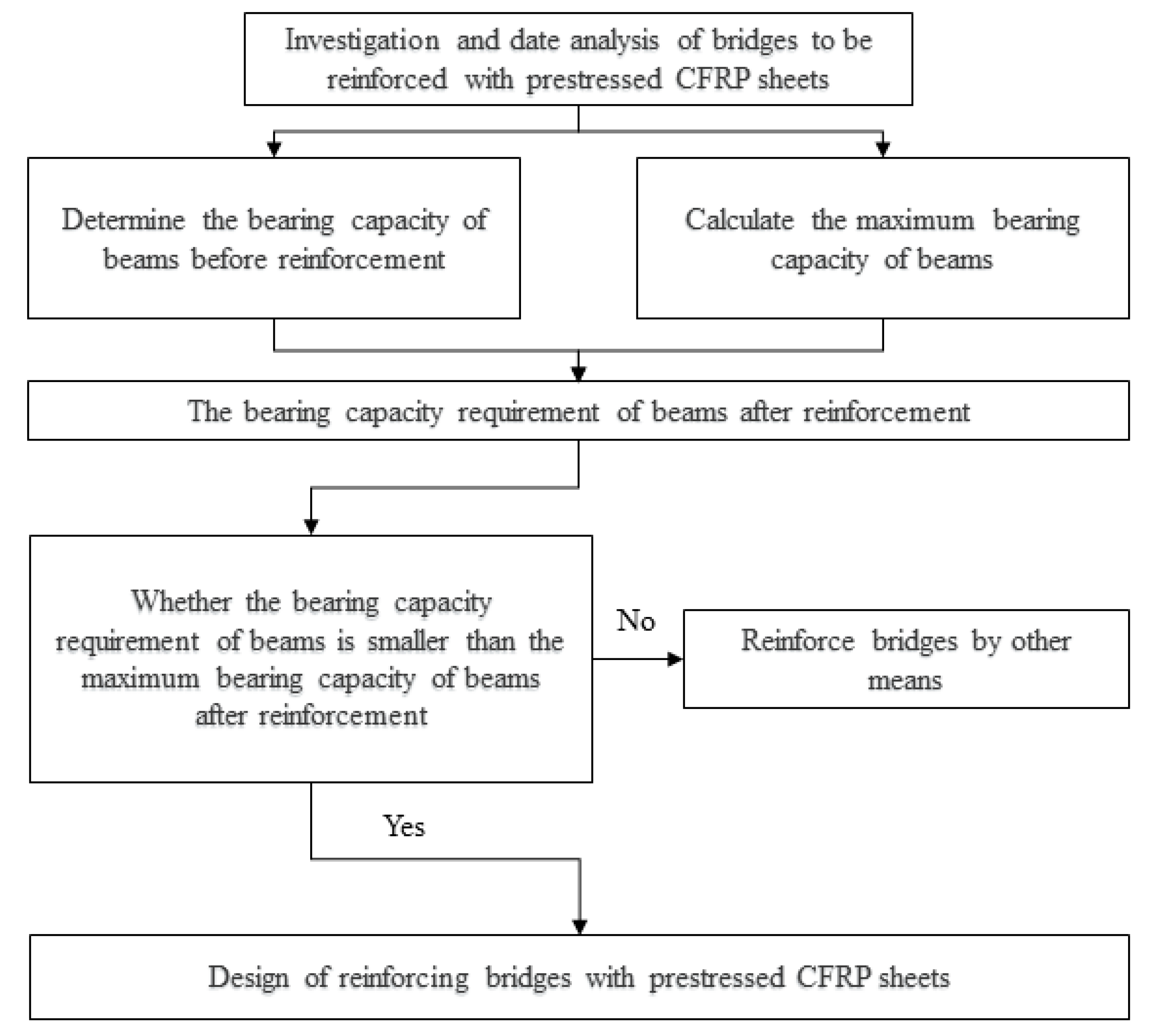
To prevent over-reinforced failure, the design flexural capacity M s of the strengthened RC beam must be less than the beam’s maximum flexural capacity M kmax [30]. The evaluation process is illustrated in Figure 3.
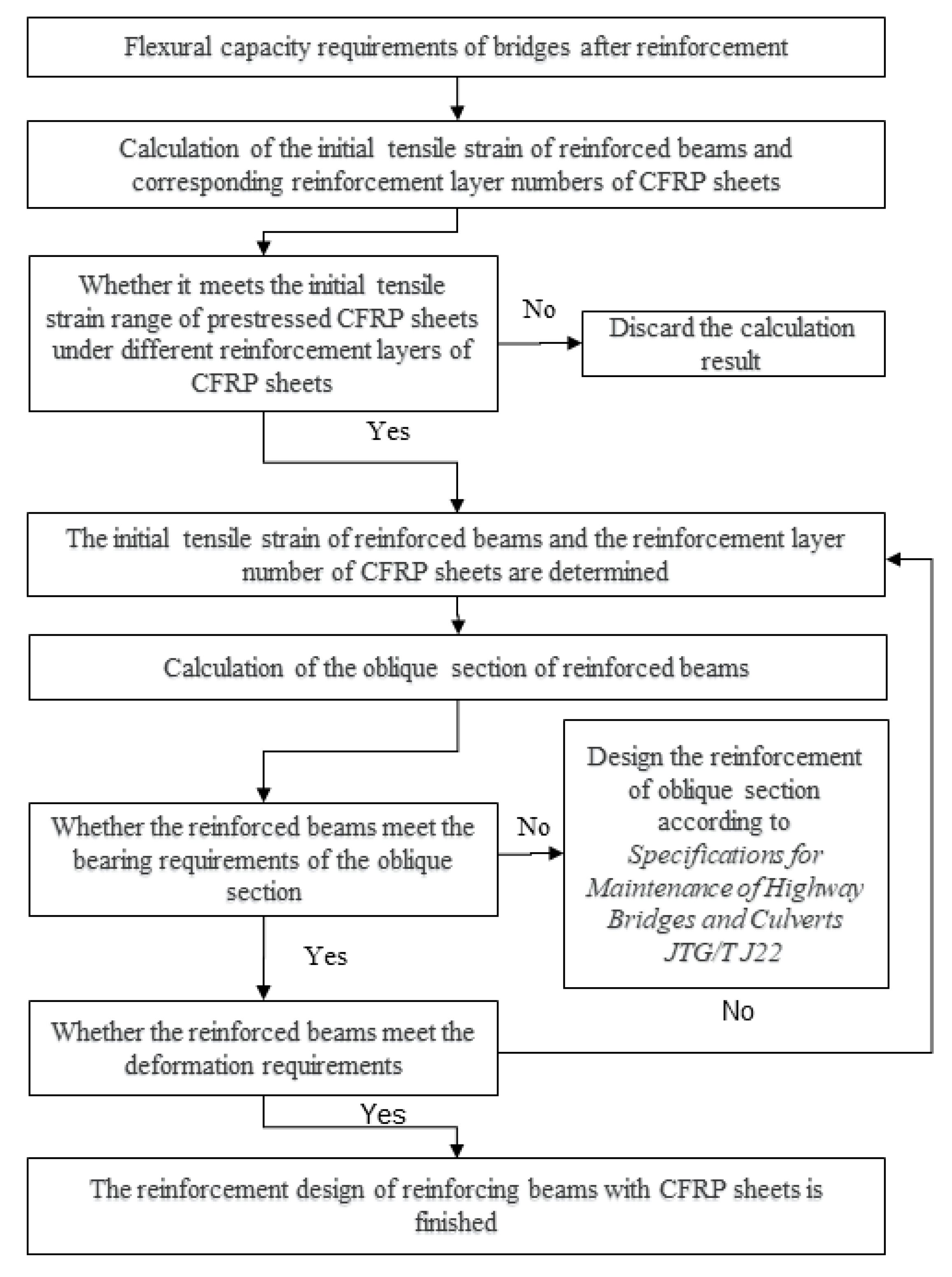
Following the evaluation process for prestressed CFRP strengthening, once an RC beam is deemed suitable for prestressed CFRP application, the strengthening design shall be initiated based on the previously established prestressed CFRP-strengthened RC beam design theory. The design procedure is illustrated in Figure 4.

3. Experimental Study on Prestressed CFRP-Strengthened RC Beams

3.1. Test Beam Design

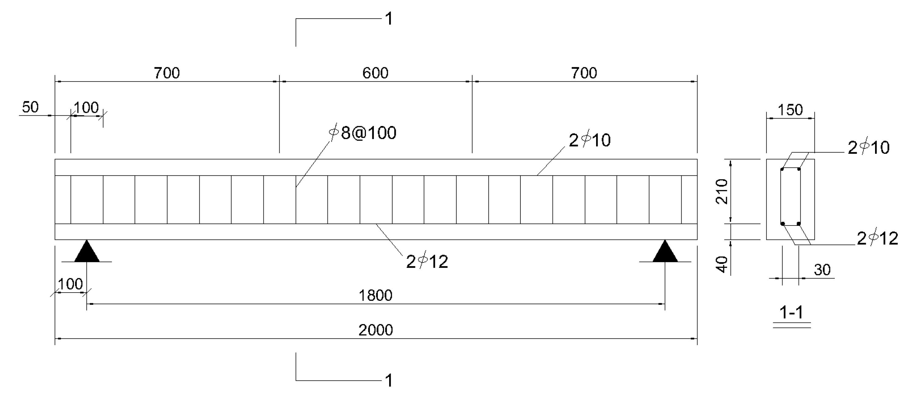
A precast reinforced concrete (RC) test beam was subjected to a four-point bending test. This test aimed at validating the accuracy of the strengthening design methodology by measuring its flexural bearing capacity and observing its failure mode. The test beam had a cross-section of 150 mm × 250 mm and a total length of 2000 mm, with a calculated span of 1800 mm and a pure bending region length of 600 mm. The test beam was cast using C30 concrete. HRB400 steel bars were employed for the tensile reinforcement and the hanger bars, with diameters of 12 mm and 10 mm, respectively. Stirrups were made using 8 mm diameter HPB300 steel bars at a clear spacing of 100 mm. The clear cover thickness was 40 mm. The beam dimensions and reinforcement details are shown in Figure 5.
While casting the test beam with C30 concrete, 150 mm side-length standard concrete cube specimens were simultaneously prepared. All specimens were cured under the same standard environmental conditions as the test beam until the age of 28 days. Three specimens with smooth surfaces and no significant defects were selected for compressive strength testing using an electro-hydraulic servo universal testing machine. The average compressive strength obtained was 30.33 MPa. During the steel bar processing, three material test coupons, each 600 mm long, were reserved from the tensile reinforcement. The mechanical properties of these coupons were tested using a microcomputer-controlled electro-hydraulic servo universal testing machine. The tensile test results for the steel bars are listed in Table 1.
This experiment utilized UT70-30-type CFRP sheets manufactured by Toray Industries, Inc., Japan, for beam strengthening. This CFRP sheet has a single-layer thickness of 0.167 mm, and its mechanical properties are presented in Table 2.
Once the concrete of the test beam reached the age of 28 days, flexural strengthening was carried out following the design theory and procedures for prestressed carbon-fiber-reinforced polymer (CFRP) sheet strengthening of RC beams.

3.2. Strengthening Design Calculation

According to Table 3, the flexural capacity at the midspan of the reference beam and the maximum flexural capacity of the singly reinforced section are referenced. With the strengthening design targeting a 30% enhancement in the flexural capacity of the reference beam after prestressed CFRP fabric reinforcement, the calculated flexural capacity of the strengthened beam is M s = 32.76 kN·m. Based on the prestressed CFRP strengthening criteria ( M s < M kmax ), the experimental beam qualifies for flexural capacity improvement using prestressed CFRP fabric.
Based on the flexural capacity M s of RC beams strengthened with CFRP sheets, calculations for the minimum required initial tensile strain ε cf 0 and the permissible initial tensile strain range with varying CFRP layers were conducted, and the results are presented in Table 4. The following is noteworthy.
With one CFRP layer, the minimum initial tensile strain must reach 0.0116, which significantly exceeds the maximum permissible value (0.0011) of its tensile strain range, failing to meet the strengthening requirements.
With two CFRP layers, the required minimum initial tensile strain is only 0.0020, representing an 82.76% reduction compared to the single-layer configuration. Simultaneously, this value of ε cf 0 = 0.0020 falls within the allowable strain range (0–0.004), satisfying the strengthening requirements.
With three CFRP layers, the calculated minimum initial tensile strain is ε cf 0 = –0.0012. This indicates that for this layer configuration, achieving the target flexural capacity M s requires the occurrence of an initial compressive strain (0.0012) in the CFRP sheets. Physically, this implies that no prestressing is needed to meet the capacity demand. However, since this minimum initial tensile strain falls below the minimum value (0) of its allowable tensile strain range, it fails to meet the strengthening requirements.
These results demonstrate that for a fixed CFRP-strengthened flexural capacity M s , increasing the number of CFRP layers substantially reduces the required initial tensile strain in the reinforcement system.

3.3. Strengthened Beam Design and Performance Prediction

To validate the accuracy of CFRP-strengthened RC beam design theory and compare performance variations across different CFRP layer counts, three beam groups were strengthened with single-, double-, and triple-layer CFRP sheets, alongside an unstrengthened reference beam as a control group. The initial tensile strain of CFRP sheets in all strengthened beams was uniformly set to 0.0020. The design parameters for the strengthened beams are detailed in Table 5.
As established by the preceding design theory and analysis in Table 4, when one layer of carbon-fiber-reinforced polymer (CFRP) with an initial tensile strain of 0.002 is applied, the design initial tensile strain fails to satisfy the required minimum design value ( ε cf 0 = 0.0116) and exceeds the maximum allowable initial tensile strain of 0.0011. Consequently, the precast reinforced concrete (RC) beam will experience premature failure due to early fracture of the CFRP under flexural loading, preventing attainment of the calculated load-bearing capacity of 29.61 kN·m. For two layers of CFRP at an initial tensile strain of 0.002, the initial tensile strain precisely equals the minimum required value ( ε cf 0 = 0.002) while satisfying the allowable strain range requirements, indicating that the strengthened RC beam will exhibit an under-reinforced failure mode under flexural loading. The calculated load-bearing capacity of 32.76 kN·m just attains the design flexural capacity M s . In the case of three CFRP layers at the same initial tensile strain of 0.002, the applied strain exceeds the required minimum ( ε cf 0 = −0.0012) but conforms to the allowable strain range. Consequently, the strengthened beam is predicted to maintain an under-reinforced failure mode under bending loads, though its calculated flexural capacity of 35.46 kN·m exceeds the design value M s .

3.4. Experimental Program for Strengthened RC Beams

To enhance the mechanical properties of precast reinforced concrete (RC) beams, this study employs dedicated tensioning equipment for prestressed strengthening using carbon-fiber-reinforced polymer (CFRP) sheets, as illustrated in Figure 6. When applying prestressing via the pre-tensioning process, five primary types of stress losses must be considered: (1) losses from CFRP sheet slippage, elastic retraction, and anchorage deformation after bonding; (2) losses induced by concrete compressive deformation during tension release; (3) losses due to concrete shrinkage and creep; (4) losses caused by stress relaxation in the CFRP sheets; (5) losses from environmental factors such as temperature and humidity variations. In the finite element modeling, these stress losses were quantified based on the computational method from [31] and deducted from the preset tension control stress baseline.
Epoxy resin serves as the critical bonding medium between CFRP sheets and concrete substrates, whose performance directly governs stress transfer efficiency and strengthening effectiveness. Substrate pre-treatment and elevated temperature control constitute key factors for achieving optimal performance [32]. To ensure effective interfacial bonding and force transfer, this study implemented the following refined construction sequence: prior to CFRP sheet application, the substrate surface was degreased with an alcohol solvent, followed by epoxy saturant coating to create a leveling layer; before tensioning, impregnating resin was applied to the CFRP sheets to ensure thorough saturation; after tensioning to target stress and anchoring, a final protective resin coating was applied. To optimize the epoxy curing kinetics and bonding performance, CFRP installation was specifically conducted under elevated ambient temperatures.
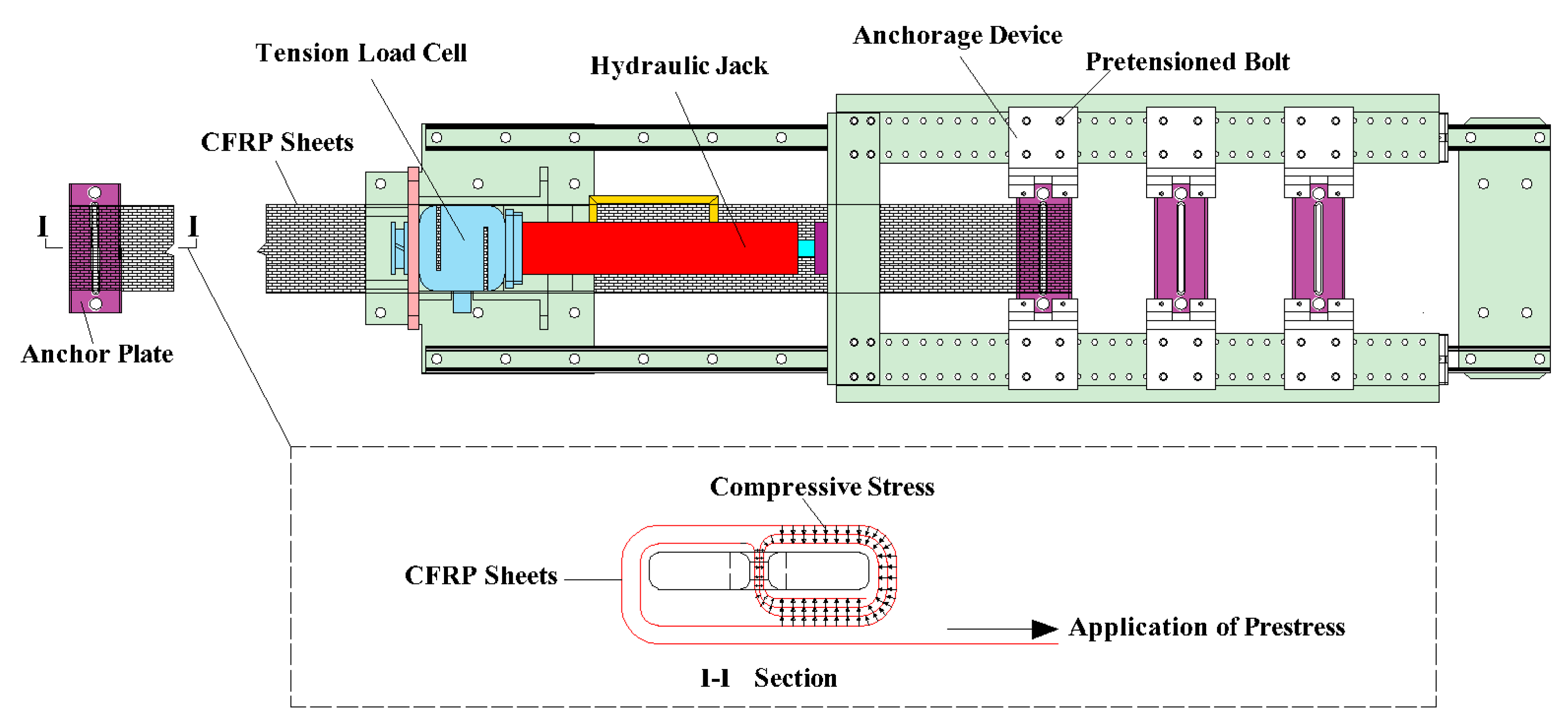
A dual anchorage mechanism was implemented during the tensioning phase to effectively mitigate prestress losses. Firstly, self-anchoring was achieved by wrapping CFRP sheets around anchorage plates, where the tensioned sheets generated radial tightening forces. This created inter-layer compression, establishing preliminary mechanical self-locking through inter-sheet friction and radial pressure. Secondly, upon reaching the preset initial tensioning stress, immediate final locking was executed using anchorage plates with torque-controlled bolts pre-set to 15 kN [33]. Schematic illustrations of the self-locking wrap and final anchorage configuration are presented in Figure 7. These dual control measures significantly reduced prestress losses in CFRP sheet post-tensioning, with measured instantaneous losses being maintained below 3%, demonstrating substantial strengthening efficacy.
The reinforced RC beams underwent 7-day ambient curing before four-point bending tests. Initial preloading was applied to eliminate interfacial gaps and verify equipment functionality. During formal loading, force control was implemented with incrementally applied loads: 2 kN increments prior to bottom cracking and 5 kN increments post-cracking. Each load level was maintained for 5 min. After reaching 50 kN, displacement control commenced at 1 mm/min [34]. Loading was terminated upon compressive crushing of concrete at the beam’s top surface, which defined failure. The test setup is illustrated in Figure 8.

4. Results and Discussion

4.1. Failure Mode

(1)
Test beam WN0
For test beam WN0, initial cracking occurred at the mid-span bottom. As loading increased, cracks propagated vertically along the beam height with continuously widening widths. Upon reaching the ultimate load, concrete in the mid-span compression zone exhibited crushing and spalling, demonstrating distinct under-reinforced failure characteristics. The final failure mode of beam WN0 is shown in Figure 9.
(2)
Test beam JN1
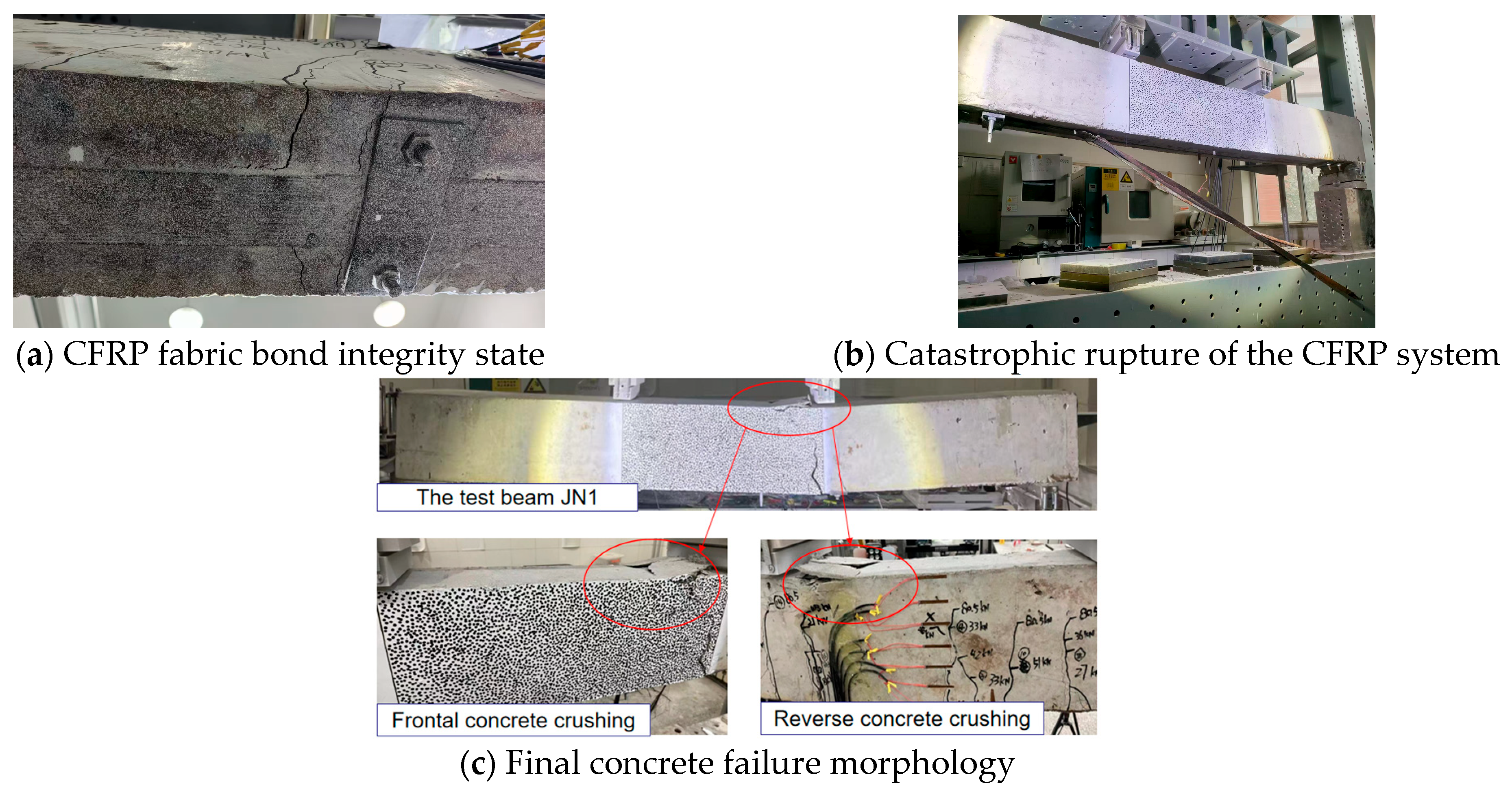
For test beam JN1, initial cracking occurred in the tension zone at the bottom of the loading point. As loading increased, cracks propagated upward continuously. Upon reaching approximately 79 kN, the tensile reinforcement yielded while the CFRP fabric maintained excellent bond integrity with minimal interfacial debonding, as illustrated in Figure 10a. Around 90 kN of loading, progressive interfacial debonding of the CFRP fabric initiated. With further displacement-controlled loading, abrupt rupture of the entire CFRP system occurred (Figure 10b), accompanied by rapid crushing failure of mid-span concrete. This failure sequence demonstrates characteristic under-reinforced behavior, visualized in Figure 10c.
(3)
Test beam JN2
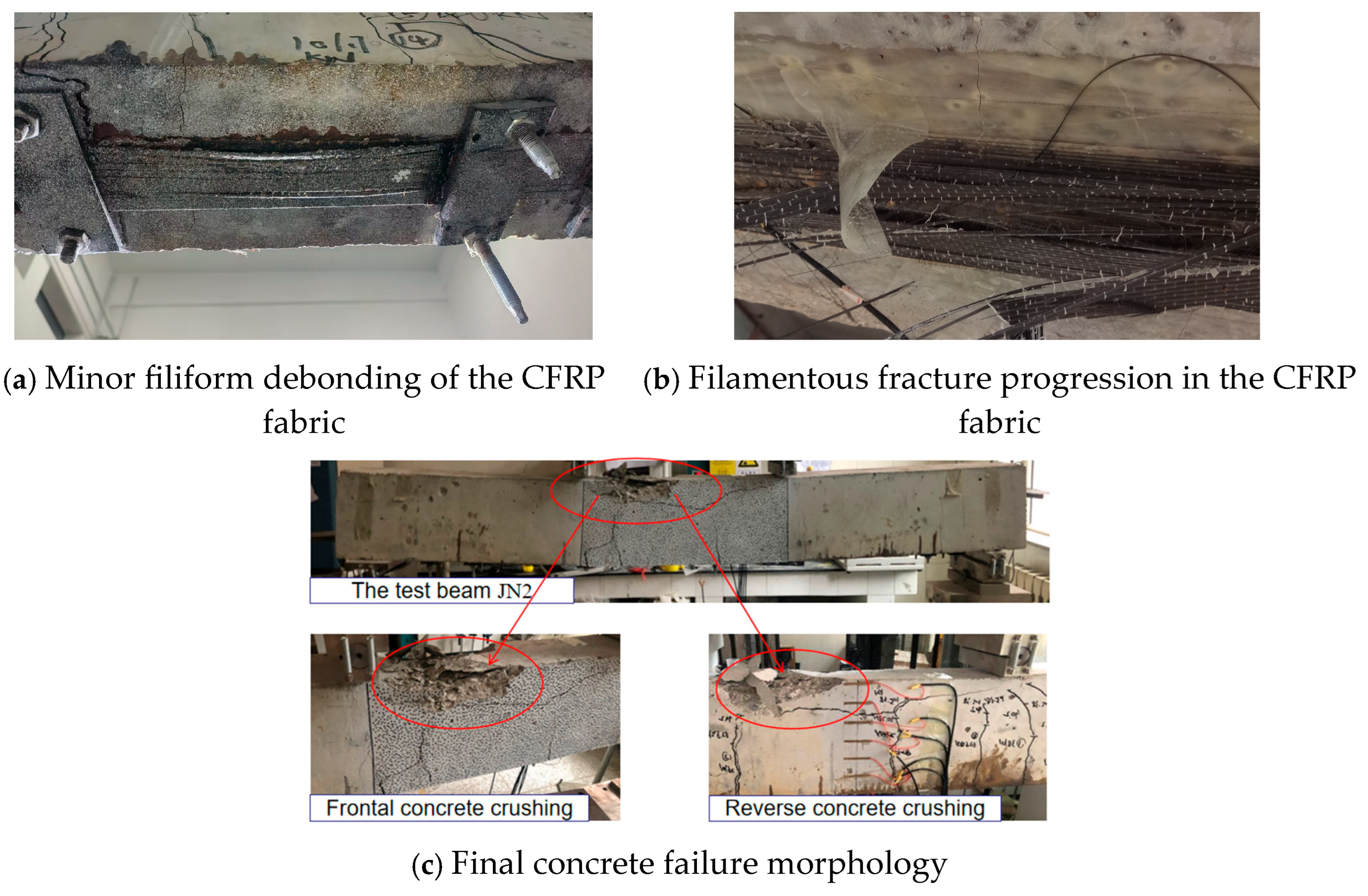
For test beam JN2, initial cracking occurred in the tension zone beneath the loading point. As the load increased, the crack width expanded while extended fractures developed. Upon reaching approximately 80 kN, tensile reinforcement yielded, after which further displacement-controlled loading produced negligible strength gain. During this stage, the CFRP fabric exhibited minor filiform debonding (Figure 11a) yet maintained effective bond integrity. When loading attained the ultimate capacity of 108.46 kN, the load-deflection curve exhibited a descending trend. This was accompanied by accelerated CFRP debonding and progressive filamentous fracture initiation (Figure 11b), culminating in concrete spalling, bulging, and ultimate crushing failure at the mid-span upper region (Figure 11c). This failure progression manifested characteristic under-reinforced behavior in the strengthened beam.
(4)
Test beam JN3
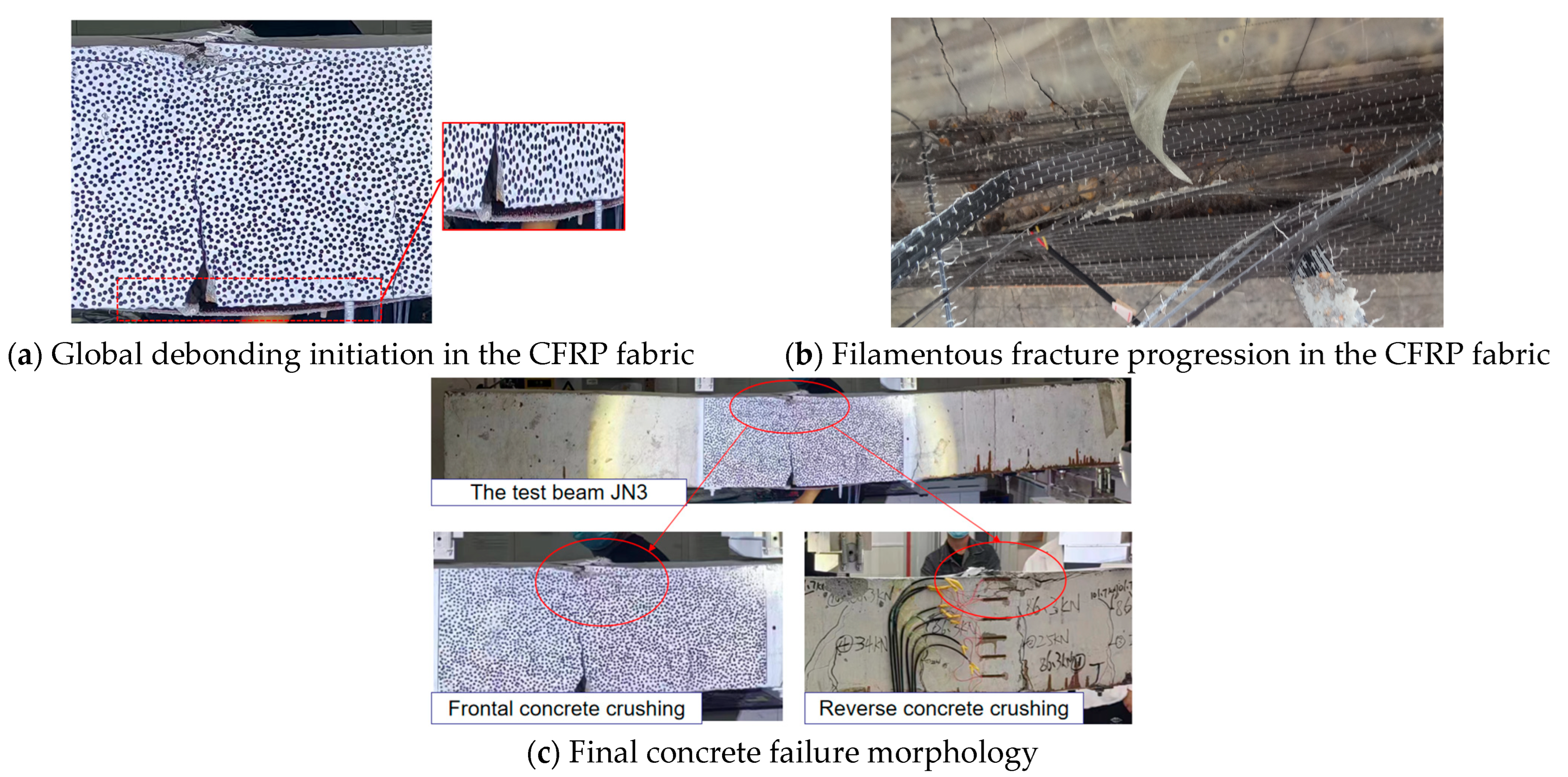
Initial cracking in the test beam commenced at the mid-span flexural zone. With increasing load, cracks propagated upward while minor global debonding initiated (Figure 12a). Tensile reinforcement yielded at approximately 83 kN. Upon reaching the ultimate load of ≈104 kN, the global debonding of CFRP intensified through a protracted detachment process, coinciding with increased deflection and gradual load reduction to 97.9 kN. Subsequent reloading produced temporary strength recovery until a filamentous fracture abruptly developed in the CFRP fabric (Figure 12b), causing a precipitous capacity drop to 75 kN without complete failure. Continued displacement-controlled loading yielded a gradual regaining of strength to ≈80 kN, where exacerbated CFRP fracture triggered another steep capacity reduction. This ultimately culminated in structural spalling and compressive fragmentation of the upper mid-span concrete (Figure 12c), demonstrating definitive under-reinforced failure behavior.

4.2. Concrete Strain Analysis

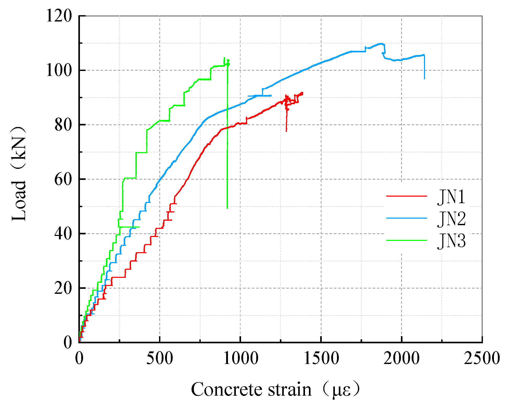
Using the compressive strain of concrete at the top of the flexural zone of the test beams as the research focus, Figure 13 presents the load–concrete strain relationship curves for different numbers of CFRP layers. The analysis results indicate the following: at the same load level, specimen JN1 exhibits the smallest concrete compressive strain, followed by JN2, and JN3 shows the largest strain. This demonstrates that increasing the amount of CFRP reinforcement can significantly enhance the overall stiffness of the strengthened beams and effectively reduce the compressive strain at the concrete top. Moreover, this enhancing effect becomes increasingly pronounced with the increase in the reinforcement amount.
After the yielding of the steel reinforcement, CFRP delamination began to occur in all three groups of beams, but the specific manifestations differed significantly. The delamination in JN1 was extremely slight, with the bond interface remaining essentially intact. Its concrete top strain grew steadily without noticeable or abrupt changes. However, as the load continued to increase, the CFRP fractured suddenly, leading to immediate beam failure, and the concrete strain did not experience a discernible ductile plateau stage. In contrast, JN2 exhibited a slightly higher degree of delamination than JN1, primarily manifested as partial debonding of individual filaments, while the main fibers maintained effective bonding. When the load reached its ultimate capacity, the CFRP underwent progressive filament fracture. The load-bearing capacity declined slightly but retained some residual strength, and the concrete strain continued to develop, demonstrating a degree of ductile behavior until final failure. JN3, however, exhibited pronounced overall delamination of the CFRP reinforcement, leading to a rapid deterioration of the interfacial bond strengthening effect. During subsequent loading, the specimen underwent a sudden overall failure, and the concrete strain similarly lacked a distinct ductile stage.
The characteristics of the concrete strain evolution detailed above are in close alignment with the failure modes of the respective specimens described in Section 3.1, thereby providing strong validation of the theoretical expectations regarding the strengthening effects and failure mechanisms.

4.3. Load-Carrying Capacity Analysis

The load versus mid-span deflection curves for both the reference beam and the strengthened beam obtained from the four-point bending tests are presented in Figure 14. Analysis of Figure 14 reveals that the test beams exhibited four distinct phases during loading. The first phase is the elastic stage, extending from the initiation of loading until cracking occurs in the concrete tensile zone. The second phase is the cracked stage, spanning from the onset of cracking in the concrete tensile zone until yielding of the tensile reinforcement. During this phase, the slope of the load-deflection curve is slightly lower than that prior to concrete cracking, indicating a reduction in the stiffness of the test beam. The third phase is the yield stage, commencing with the yielding of the tensile reinforcement and continuing until the load exhibits a pronounced descending trend. Following the yielding of the tensile reinforcement, the stiffness of the test beam decreased rapidly, accompanied by a slow increase in load while the deflection increased sharply. The fourth phase is the failure stage, characterized by a rapid decline in load until the concrete in the compressive zone of the test beam is crushed. Notably, the load-deflection curve for specimen JN3 exhibits a distinct steep descent during the failure stage. This is attributed to the premature occurrence of extensive debonding in the CFRP laminate of JN3 prior to reaching its ultimate load-carrying capacity. The resultant abrupt deterioration in strengthening effectiveness and inadequate structural integrity led to the sudden fracture of the beam.
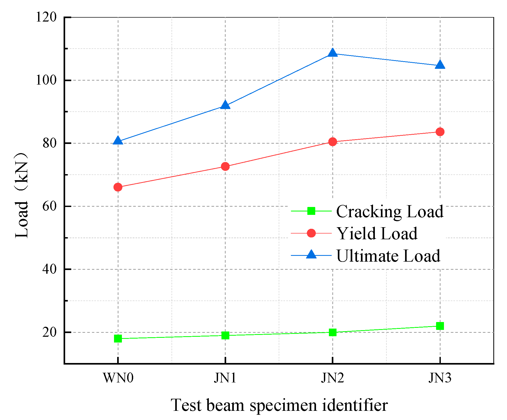
A comparison of the characteristic curve values for the test beams is presented in Figure 15. Analysis of the results in Figure 15 reveals that prior to failure, both the cracking load and the yield load of the strengthened beams increased with the number of CFRP layers, aligning with the theoretical design predictions. However, the increase in cracking load became less pronounced with additional CFRP layers. When the number of CFRP layers was less than 3, the increase in yield load became more significant with more layers; specimens JN1 and JN2 exhibited yield load increases of 10% and 22%, respectively, compared with the reference beam WN0. However, with three layers of CFRP (JN3), the improvement in yield load was negligible; JN3 showed only an approximately 4% increase compared to JN2. This indicates a reduction in overall stiffness for JN3 due to CFRP debonding. When the number of CFRP layers was less than 3, the ultimate load increased with the number of layers, consistent with the earlier prediction. However, the ultimate load-carrying capacity of JN3 was lower than that of JN2, diverging from theoretical predictions. The primary reason is the premature occurrence of extensive debonding in the CFRP of JN3, resulting in a significant reduction in strengthening effectiveness, which consequently led to a decrease in the load-carrying capacity of the strengthened beam.
The flexural capacity results for both the reference beam and the strengthened beams are presented in Table 6. Analysis of Table 6 indicates that the test result of the flexural capacity at mid-span for the unstrengthened beam WN0 closely matches its calculated value, with a difference of merely 1.06 kN and an error of approximately 4%. This confirms the reasonable design of the dimensions and reinforcement for the reference beam. For specimen JN1, the test result of the flexural capacity at mid-span (27.56 kN·m) was approximately 2.05 kN less than its calculated value (29.61 kN·m). Furthermore, the underlying cause is that the CFRP fractured prematurely due to its initial tensile strain exceeding the maximum permissible initial tensile strain. This premature fracture resulted in the test result being lower than the calculated flexural capacity. Additionally, since the initial tensile strain was also less than the minimum required initial pre-strain, the actual flexural capacity achieved was only 27.56 kN·m, which was significantly lower than its design value M s = 32.76 kN·m. These results align with the theoretical predictions from the design stage. For specimen JN2, the initial tensile strain in the CFRP precisely met the requirement for the minimum initial pre-strain and was within the acceptable range. Consequently, the test result of its flexural capacity at mid-span was virtually identical to the calculated value, differing by only 0.22 kN (error ≈ 0.67%). This consistency is also in agreement with theoretical predictions. For specimen JN3, the calculated flexural capacity at mid-span was 35.46 kN. However, its actual test result was only 31.39 kN·m, which is less than its design capacity of M s = 32.76 kN·m. This deviates considerably from the theoretical predictions. The primary reason is the occurrence of extensive debonding of the CFRP in JN3 before it could reach its ultimate flexural capacity. This led to a significant degradation in the strengthening effectiveness, consequently causing the actual test result to fall below the calculated flexural capacity.
In summary, when reinforced with less than three layers of CFRP sheets, the experimental phenomena and results of the strengthened beams were in good agreement with the theoretical predictions, validating the accuracy of the design theory for prestressed CFRP-strengthened RC beams presented in this paper. However, when the reinforcement reached three layers, the experimentally measured flexural capacity was significantly lower than the theoretically calculated value. This discrepancy is primarily attributed to the substantial increase in the overall stiffness of the CFRP due to multi-layer lamination, which exacerbated the stiffness disparity between the CFRP and the concrete substrate. This increased stiffness difference led to significantly elevated peak interfacial shear stresses and normal stresses under load, concurrently causing an increase in shear stresses between CFRP layers. The excessively high and unevenly distributed stress concentrations readily induced stresses exceeding the ultimate strength of the adhesive in localized areas, thereby triggering delamination failure of the entire CFRP sheet [35,36]. This delamination behavior violates a fundamental assumption of the design theory—a reliable bond between the FRP sheet and the concrete. For CFRP strengthening with one to two layers, the bond performance remains effective, and the design theory exhibits good applicability and reliability. As the number of layers increases, the risk of interfacial bond failure increases significantly, invalidating the theoretical assumption.
Current research indicates that CFRP strengthening exceeding two layers not only offers limited effectiveness in controlling cracking within concrete structures and increases engineering costs but also tends to result in the underutilization of the material’s potential. Furthermore, excessive reinforcement may trigger unpredictable and undesirable failure modes that are difficult to control [19]. Therefore, the prestressed CFRP-strengthened RC beam design theory established in this paper can adequately meet engineering demands within the range of one to two layers of reinforcement.

5. Conclusions and Future Work

5.1. Conclusions

This paper systematically proposed a design theory and methodology for prestressed carbon-fiber-reinforced polymer (CFRP)-sheet-strengthened reinforced concrete (RC) beams through theoretical analysis and experimental investigation. The main conclusions are as follows.
(1)
This study established a design theory for prestressed CFRP-strengthened RC beams. By strictly limiting the initial prestressing strain range, the theory effectively prevents brittle failure due to over-strengthening. The experimental results demonstrated strong agreement with the theoretical predictions, confirming the proposed theory’s reliability and practical applicability for typical strengthening scenarios.
(2)
An increase in CFRP layers can effectively enhance the overall stiffness of strengthened beams; however, employing more than two layers may exacerbate CFRP delamination, consequently leading to a reduction in the load-bearing capacity along with diminished strengthening effectiveness.
(3)
The proposed optimized schemes—self-locking winding and pre-tightened bolt anchorage—effectively mitigated prestress loss and ensured high tensioning efficiency. Nevertheless, the quality of the bond at the CFRP–concrete interface is the critical factor limiting the effectiveness of the strengthening, particularly for multi-layer applications.

5.2. Future Work

Building upon the limitations identified in this study and engineering demands, future research should be deepened in the following three areas.
(1)
Given that this study has not yet fully revealed the microscopic mechanisms of interfacial failure in multi-layer CFRP strengthening, future work should incorporate micro-characterization techniques such as SEM/XCT [37,38]. This will enable the quantitative analysis of interfacial shear stress distribution, crack propagation, and bond degradation laws. A predictive model for the “layer number–stiffness–delamination threshold” should be established to achieve a breakthrough beyond the current layer limitation.
(2)
To facilitate the translation of laboratory findings into engineering practice, validation via full-scale beam-strengthening tests (TRL 6), in-service monitoring of environmental durability, and research on standardized construction methodologies are required.
(3)
The scope should be extended to scenarios such as continuous beams and beams with variable cross-sections. Furthermore, long-term performance tests of strengthened beams under fatigue and impact loads should be conducted.

Author Contributions

Methodology, Y.Q. (Yu Qin); Validation, Y.R.; Data curation, G.L., Y.G., Y.W. and Y.Q. (Yuanshun Qian); Writing—original draft, Z.Z.; Writing—review & editing, Y.Q. (Yu Qin)and Y.R.; Supervision, Renjuan Sun; Project administration, R.S. All authors have read and agreed to the published version of the manuscript.

Funding

This research was funded by the Natural Science Foundation of Shandong Province, China (Grant Number ZR2021ME215), supporting the project ‘Study on Mechanical Behavior and Chloride Ion Transport Behavior of ECC-Reinforced Concrete Functionally Graded Beams’. The Article Processing Charge (APC) was funded by Shandong Hi-Speed Group Co., Ltd.

Data Availability Statement

The original contributions presented in this study are included in the article. Further inquiries can be directed to the corresponding author.

Conflicts of Interest

Authors Zejun Zhang and Guanxu Long were employed by the company Shandong Expressway Group Co., Ltd. The remaining authors declare that the research was conducted in the absence of any commercial or financial relationships that could be construed as a potential conflict of interest.

References

  1. Al-Mosawe, D.; Neves, L.; Owen, J. Reliability analysis of deteriorated post-tensioned concrete bridges: The case study of Ynys-y-Gwas bridge in UK. Structures 2022, 41, 242–259. [Google Scholar] [CrossRef]
  2. Jiang, X.; Cao, D.; Qiang, X.; Xu, C. Study on fatigue performance of steel bridge welded joints considering initial defects. J. Constr. Steel Res. 2024, 212, 108309. [Google Scholar] [CrossRef]
  3. Borrie, D.; Al-Saadi, S.; Zhao, X.-L.; Raman, R.S.; Bai, Y. Bonded CFRP/Steel Systems, Remedies of Bond Degradation and Behaviour of CFRP Repaired Steel: An Overview. Polymers 2021, 13, 1533. [Google Scholar] [CrossRef] [PubMed]
  4. United States. Department of Transportation. University Transportation Centers (UTC) Program, United States. Department of Transportation. Federal Highway Administration, Haifang Wen, Pizhong Qiao, Ayumi K Manawadu, Washington State University. Department of Civil and Environmental Engineering, and Washington State University. National Center for Transportation Infrastructure Durability & Life Extension (TriDurLE) UTC.Test Methods and Bond Performance Characterization of Shotcrete-Concrete Interface. Available online: https://research.ebsco.com/linkprocessor/plink?id=de2e7ea4-1160-3185-a3ce-aef5b0d3c93c (accessed on 14 August 2025).
  5. Chalot, A.; Michel, L.; Ferrier, E. Experimental study of external bonded CFRP-concrete interface under low cycle fatigue loading. Compos. Part B Eng. 2019, 177, 107255. [Google Scholar] [CrossRef]
  6. Lee, T.; Jeong, S.; Woo, U.; Choi, H.; Jung, D. Experimental Evaluation of Shape Memory Alloy Retrofitting Effect for Circular Concrete Column Using Ultrasonic Pulse Velocity. Int. J. Concr. Struct. Mater. 2023, 17, 13. [Google Scholar] [CrossRef]
  7. Aslam, M.; Shafigh, P.; Jumaat, M.Z.; Shah, S. Strengthening of RC beams using prestressed fiber reinforced polymers–A review. Constr. Build. Mater. 2015, 82, 235–256. [Google Scholar] [CrossRef]
  8. Li, D.; Zhu, R.; Li, F. Flexural Behavior of GFRP–Aluminum Space Truss Strengthened with Prestressed CFRP Tendons: Experimental and Theoretical Study. J. Compos. Constr. 2024, 28, 04024036. [Google Scholar] [CrossRef]
  9. Basaran, B.; Kalkan, I.; Bergil, E.; Erdal, E. Estimation of the FRP-concrete bond strength with code formulations and machine learning algorithms. Compos. Struct. 2021, 268, 113972.1–113972.16. [Google Scholar] [CrossRef]
  10. Slaitas, J.; Valivonis, J. Technological peculiarities of strengthening RC members with prestressed FRP laminates. Compos. Struct. 2022, 290, 115526. [Google Scholar] [CrossRef]
  11. Tang, Y.; Yao, Y.; Cang, J. Structural and Sensing Performance of RC Beams Strengthened with Prestressed Near-Surface Mounted Self-Sensing Basalt FRP Bar. Compos. Struct. 2020, 259, 113474. [Google Scholar] [CrossRef]
  12. Jiang, F.; Ding, Y.; Song, Y.; Yang, K. Fatigue enhancement in complex U-rib to diaphragm welds via rib-surface-bonded CFRP plates: Performance evaluation and configuration design. Adv. Struct. Eng. 2025, 28, 488–512. [Google Scholar] [CrossRef]
  13. Cho, S.; Lee, H.; Chung, W. Strengthening effect of prestressed near-surface mounted CFRP bar system according to material properties of aged reinforced concrete beams. Compos. Struct. 2020, 282, 115121. [Google Scholar] [CrossRef]
  14. Belarbi, A.; Reda, M.; Poudel, P.; Tahsiri, H.; Dawood, M.; Gencturk, B. Prestressing Concrete with CFRP Composites for Sustainability and Corrosion-Free Applications. MATEC Web Conf. 2018, 149, 01010. [Google Scholar] [CrossRef][Green Version]
  15. Alsuhaibani, E. Optimization of Carbon Fiber-Reinforced Polymer (CFRP) Configuration for Enhanced Flexural Performance in Strengthened Concrete Beams. Buildings 2024, 14, 3953. [Google Scholar] [CrossRef]
  16. Bensaid, C.; Tbatou, T. Numerical studies on the seismic behavior of reinforced concrete structures Strengthened with CFRP. J. Build. Pathol. Rehabil. 2024, 9, 148. [Google Scholar] [CrossRef]
  17. Lu, C.; Chen, J.; Gan, X.; Wang, Q.; Zhu, W.X. Experimental study on the prestress loss of double-end prestressing of carbon-fiber reinforced polymer fabric for strengthening large-diameter reinforced concrete circular columns. Polym. Compos. 2023, 44, 1772–1788. [Google Scholar] [CrossRef]
  18. LI, A.; Diagana, C.; Delmas, Y.; Gedalia, B. Shear performance with externally bonded carbon fibre fabrics. In Fibre-Reinforced Polymer Reinforcement for Concrete Structures; World Scientific: Singapore, 2015. [Google Scholar]
  19. Liu, J.; Fan, X.; Zou, L.; Shi, C. Effect of different CFRP strengthening methods on fracture parameters of concrete beam. Eng. Fract. Mech. 2025, 314, 110748. [Google Scholar] [CrossRef]
  20. Al-Rousan, R.; Al-Saraireh, S. Impact of Anchored Holes Technique on Behavior of Reinforced Concrete Beams Strengthened with Different CFRP Sheet lengths and Widths. Case Stud. Constr. Mater. 2020, 13, e00405. [Google Scholar] [CrossRef]
  21. Hanoon, A.N.; Jaafar, M.; Al Zaidee, S.R.; Hejazi, F.; Abd Aziz, F. Effectiveness factor of the strut-and-tie model for reinforced concrete deep beams strengthened with CFRP sheet. J. Build. Eng. 2017, 12, 8–16. [Google Scholar] [CrossRef]
  22. Zhang, Z.; Wang, W.; Zhen, J.; Li, B.; Cai, D.; Du, Y. Entire mechanical analysis of prestressed CFRP strengthened RC beams under different prestressed introduced methods. Adv. Bridge Eng. 2024, 5, 13. [Google Scholar] [CrossRef]
  23. Fowai, I.; Noël, M.; Esmaili, M.; Martín-Pérez, B.; Sanchez, L. Bond performance of deteriorated CFRP-concrete interface under different shear lap configurations: A Champlain Bridge case study. Constr. Build. Mater. 2025, 487, 142002. [Google Scholar] [CrossRef]
  24. Lu, Z.; Li, J.; Xie, J.; Huang, P.; Xue, L. Durability of flexurally strengthened RC beams with prestressed CFRP sheet under wet–dry cycling in a chloride-containing environment. Compos. Struct. 2020, 255, 112869. [Google Scholar] [CrossRef]
  25. Shang, S.; Peng, H.; Tong, H.; Wei, D.; Zeng, L. Study of strengthening reinforced concrete beam using prestressed carbon fiber sheet. J. Build. Struct. 2003, 24, 24–30. [Google Scholar]
  26. GB 50367-2013; Code for Design of Strengthening Concrete Structure. Chinese Standard: Beijing, China, 2013.
  27. Wang, W. FRP Strengthened Concrete Structures: Techniques and Applications; Architecture & Building Press: Beijing, China, 2007. [Google Scholar]
  28. GB 50010-2010; Code for Design of Concrete Structure. Chinese Standard: Beijing, China, 2010.
  29. CECS 146-2003(2007); Technical Code for Strengthening Concrete Structures with Carbon Fiber Reinforced Sheets. Chinese Standard: Beijing, China, 2003.
  30. Ye, J. Principles of Structural Design, 4th ed.; Communications Press: Beijing, China, 2018; pp. 68–69. [Google Scholar]
  31. Zheng, X.; Huang, P.; Huang, J. Experimental study on prestress loss of reinforced concrete beams strengthened with prestressed carbon fiber laminates. J. Build. Struct. 2015, 36, 7. [Google Scholar]
  32. Kazemi, F.; Asgarkhani, N.; Shafighfard, T.; Jankowski, R.; Yoo, D.-Y. Machine-Learning Methods for Estimating Performance of Structural Concrete Members Reinforced with Fiber-Reinforced Polymers. Arch. Comput. Methods Eng. 2025, 32, 571–603. [Google Scholar] [CrossRef]
  33. Guan, Y.; Miao, H.; Song, X. Study of the anchoring parameter for the hybrid bonding of FRP. J. Shandong Univ. (Eng. Sci.) 2010, 40, 128–132. [Google Scholar]
  34. Wu, F.; Wu, J.; Bian, Z.; Ma, Y.; Li, Z.; Lei, H. Experimental study on flexural behavior of ECC-NC composite beams. China J. Highw. Transp. 2025, 38, 158–172. [Google Scholar]
  35. Abdulrahman, B.Q. Precise finite element verification of the unreliability of using multi-layers of FRP on CFRP-debonding in RC beams. Eng. Res. Express 2022, 4, 025048. [Google Scholar] [CrossRef]
  36. Thamrin, R.; Zaidir, Z.; Desharma, S. Debonding failure analysis of reinforced concrete beams strengthened with CFRP plates. Polymers 2021, 13, 2738. [Google Scholar] [CrossRef]
  37. Chou, H.Y.; Bunsell, A.R.; Thionnet, A. Visual indicator for the detection of end-of-life criterion for composite high pressure vessels for hydrogen storage. Int. J. Hydrog. Energy 2012, 37, 16247–16255. [Google Scholar] [CrossRef]
  38. Sakr, M.A. Finite element modeling of debonding mechanisms in carbon fiber reinforced polymer-strengthened reinforced concrete continuous beams. Struct. Concr. J. FIB 2018, 19, 1002–1012. [Google Scholar] [CrossRef]
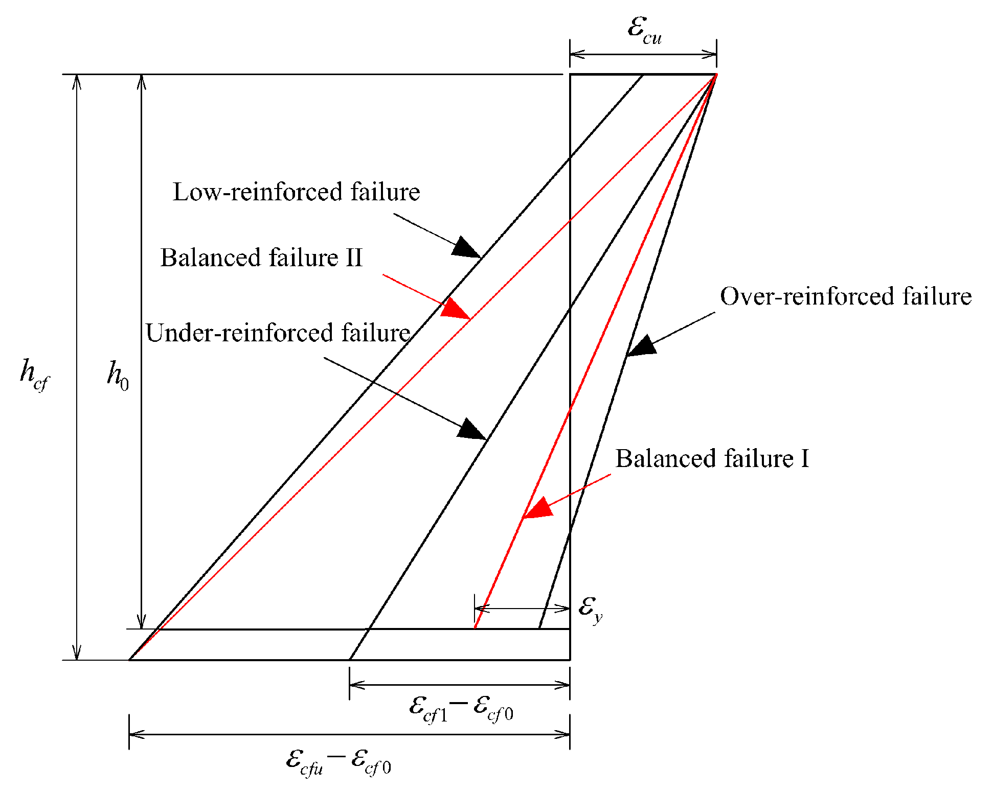
Figure 1. Failure model distribution of an RC beam reinforced with prestressed carbon fiber sheets.
Buildings 15 03126 g001
Figure 2. Strain and stress relationship of the normal section of reinforced beams.
Buildings 15 03126 g002
Figure 3. Judging process for prestressed carbon fiber sheet reinforcement.
Buildings 15 03126 g003
Figure 4. The design theory for strengthening RC beams using prestressed carbon fiber sheets.
Buildings 15 03126 g004
Figure 5. Schematic illustration of test beam dimensions and reinforcement details (unit: mm).
Buildings 15 03126 g005
Figure 6. Photograph of dedicated tensioning equipment for CFRP sheets.
Buildings 15 03126 g006
Figure 7. Schematic diagram of the CFRP sheet tensioning process.
Buildings 15 03126 g007
Figure 8. Loading test device (unit: mm).
Buildings 15 03126 g008
Figure 9. Failure mode of test beam WN0.
Buildings 15 03126 g009
Figure 10. Failure sequence of test beam JN1.
Buildings 15 03126 g010
Figure 11. Failure sequence of test beam JN2.
Buildings 15 03126 g011
Figure 12. Failure sequence of test beam JN3.
Buildings 15 03126 g012
Figure 13. Load–strain behavior of concrete at the top surface in the pure bending zone.
Buildings 15 03126 g013
Figure 14. Load versus mid-span deflection curves for the reference beam and strengthened beams.
Buildings 15 03126 g014
Figure 15. Comparison of characteristic values for the test beams.
Buildings 15 03126 g015
Table 1. Tensile performance test results for reinforcement.
Reinforcement TypeDiameter (mm)Yield Strength
(MPa)
Ultimate Strength
(MPa)
Modulus of Elasticity
(MPa)
HRB40012429.88594.08308,000
Table 2. Mechanical properties of the CFRP fabric.
MaterialTensile Strength (MPa)Elastic Modulus (MPa)Percentage Elongation (%)
CFRP42552.4 × 1051.9
Table 3. Summary of the flexural capacity calculation for control beams.
Experimental Beam TypeMidspan Flexural Capacity of Normal Section (kN·m)Maximum Flexural Capacity of Singly Reinforced Section (kN·m)
Control beam25.247.94
Table 4. Minimum initial tensile strain and allowable strain range for varying numbers of CFRP layers.
CFRP Layer Count ε cf 0 Initial Tensile Strain Range
10.0116 0 < ε cf 0 < 0.0011
20.0020 0 < ε cf 0 < 0.0025
3−0.0012 0 < ε cf 0 < 0.0036
Notes: 1. The design width of CFRP sheets is 50 mm. 2. According to the Design Code for Strengthening Concrete Structures, the layer count for CFRP strengthening should generally not exceed 4 layers. In practical applications, CFRP sheets are typically applied in ≤3 layers; conse-quently, this table calculates initial tensile strain values only for 1–3 layers. 3. The permissible strain for CFRP sheets is specified as 0.01 in the Technical Specification for Strengthening Concrete Structures with Carbon Fiber Sheets.
Table 5. Design parameters for prestressed CFRP-strengthened RC beams.
Specimen IDNumber of CFRP Layers ε cf 0 Initial Prestressing Force Per CFRP Layer (kN)Calculated Mid-Span Flexural Capacity (kN·m)
WN00--25.20
JN110.0020429.61
JN220.0020432.76
JN330.0020435.46
Note: In the specimen IDs, W and J denote unreinforced RC beams and strengthened RC beams, respectively; N indicates the number of carbon-fiber-reinforced polymer (CFRP) layers.
Table 6. Comparison of the flexural capacity results between the reference beam and the strengthened beams.
Specimen IDCalculated Mid-Span Flexural Capacity (kN·m)Tested Mid-Span Flexural Capacity (kN·m)
WN025.2024.14
JN129.6127.56
JN232.7632.54
JN335.4631.39
Disclaimer/Publisher’s Note: The statements, opinions and data contained in all publications are solely those of the individual author(s) and contributor(s) and not of MDPI and/or the editor(s). MDPI and/or the editor(s) disclaim responsibility for any injury to people or property resulting from any ideas, methods, instructions or products referred to in the content.