Article

Stress and Deformation Control of Active Pile Foundation of Tunnel Underpass Bridge Based on Field Monitoring

1
College of Urban and Rural Construction, Zhongkai University of Agricultural Engineering, Guangzhou 510225, China
2
Guangdong Jianke Architectural Design Institute Co., Ltd., Guangzhou 510440, China
3
School of Architecture and Transportation Engineering, Guilin University of Electronic Technology, Guilin 541004, China
*
Authors to whom correspondence should be addressed.
Buildings 2025, 15(17), 3034; https://doi.org/10.3390/buildings15173034
Submission received: 6 July 2025 / Revised: 14 August 2025 / Accepted: 20 August 2025 / Published: 26 August 2025

Abstract

The active pile underpinning technology when a tunnel passes under a bridge involves complex force conditions, making construction monitoring and control extremely challenging. However, there is a lack of research on the laws governing the stress and deformation responses of bridges during the construction process. This paper takes an active pile underpinning project of a metro line passing under a bridge as a case study. Design and construction plans are taken as the basis, and on-site monitoring data are incorporated. A three-dimensional finite element simulation model is established. This model is used to analyze the distribution and variation laws of stress and settlement during the pile underpinning process. The results show that: considering the traffic conditions of the bridge and the requirements for additional stress, it is reasonable to suggest that the actual settlement of the bridge deck should be 2–3 mm; the determination of the jacking force should generally be greater than the load transmitted from the pier column to the underpinning beam and less than 75% of the maximum bearing capacity, which is more reasonable.

1. Introduction

With the rapid development of urban rail transit, the spatial intersections between newly-built metro tunnels and pile foundations of existing structures have become increasingly prominent. When a metro tunnel passes under a viaduct, if it intersects with the pile foundations of the viaduct, it is usually required to complete the construction of the tunnel crossing the obstacle piles on the premise of not affecting the safe operation of the bridge. Therefore, in such cases, only pile foundation underpinning technology can be adopted to enable the metro tunnel to pass through the existing pile foundations. Conventional pile foundation underpinning generally adopts the ground beam-type underpinning system [1,2]. During the construction process, supporting piles and bearing platform beams are first constructed; then, the underpinning pile caps and existing supporting structures are integrated into a whole by means of the bar planting method; finally, the existing piles under the bearing platform beams are cut off. Pile foundation underpinning projects need to ensure the safety of normal traffic on the bridge, with more complex stress conditions and high difficulty in construction control. Therefore, it is necessary to study their load-bearing and reinforcement mechanisms, as well as the stress and displacement response laws of pile foundations, bearing platform beams, and upper bridge decks during construction, so as to put forward targeted deformation control measures.
Currently, studies on pile foundation underpinning technology have been relatively limited. Chen Juwu, Zhang Tao, Liang Yuehua et al. [3,4,5] introduced the design and construction scheme and proposed a reasonable underpinning scheme according to the actual situation. Huang Shenggen, Sheng, Chen Xinlei et al. [6,7,8] studied the mechanical performance and deformation characteristics of the main structure, and put forward the control requirements for force and displacement. Lü Wenda, Li Hong et al. [9,10,11] studied the reinforcement effect of active underpinning using methods such as numerical simulation. Yang Zhenghua and Zang Yanwei [12,13] conducted research on control measures such as displacement based on on-site monitoring technology. The above research indicates that there is still a lack of research on the stress and displacement response of pile underpinning beams and bridges during the underpinning process based on monitoring data. Moreover, studies on the corresponding deformation control range and jacking force control are limited.
Relying on the pile underpinning project of a subway tunnel underpassing a bridge in Guangzhou, this paper, based on field-measured data and combined with numerical simulation, studies the stress and deformation response characteristics of the bridge deck and cap beams caused by the construction process, as well as the control indicators of settlement and jacking force.

2. Project Overview

A subway tunnel in Guangzhou is constructed using the shield tunneling method, with the buried depth of the tunnel crown ranging from approximately 13.32 m to 18.82 m. The tunnel traverses beneath a municipal bridge pile foundation section. The bridge substructure consists of single-column piers and portal piers supported by bored cast-in-place piles with diameters of 1.5 m and 1.8 m, respectively. The pile foundations are embedded in moderately weathered limestone as the bearing stratum. The minimum horizontal clearance between the shield tunnel and the bridge piles is 1.18 m. Given the need for the subway tunnel to pass beneath the bridge pile foundations, active pile foundation underpinning is required. The tunnel segment subject to underpinning primarily traverses silty clay and moderately weathered limestone strata. The project overview is illustrated in Figure 1.

3. Scheme and Construction of Tunnel Underpass Bridge Pile

3.1. Design Scheme of Underpass Bridge Pile

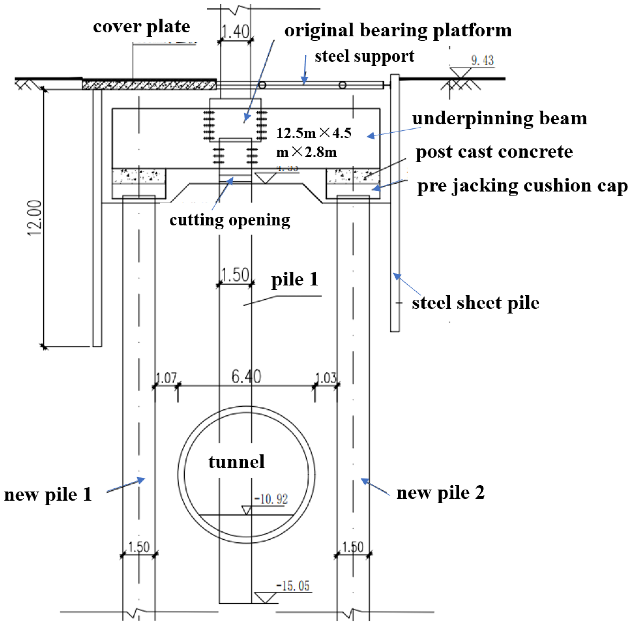
Comprehensively considering that active pile foundation underpinning projects need to ensure the bridge remains passable, the restricted construction height of foundation piles under the bridge, and that ground construction shall not affect traffic, among other factors, the project employs a platform-type active underpinning system. The underpinning foundation piles and platform are constructed first, with a pre-set gap between the piles and the existing cap beam. Hydraulic jacks are installed within this gap. Through controlled jacking, the original foundation is unloaded until the axial force in the original piles reaches zero. The support structure is then erected, the original piles are truncated, and the gap is filled with concrete. Once the underpinning system is completed, the shield machine can proceed to cut through the residual pile segments. The detailed design is illustrated in Figure 2, with the key components outlined below:
(1)
The underpinning foundation pit is supported by Larsen IV steel sheet piles with ∅325 × 10 steel pipe struts; local concrete slabs are installed to maintain traffic flow during construction.
(2)
The underpinning beams and caps are constructed using C40 concrete, the post-cast closure segment uses C40 micro-expansion concrete, and a 200 mm-thick C20 concrete cushion is placed beneath the underpinning elements.
(3)
The underpinning piles are cast using C35 underwater concrete, with lengths determined by site conditions. If karst features are encountered, piles shall be embedded 1.0 m into slightly weathered bedrock below the cave, ensuring a minimum of 5 m of intact rock beneath the pile tip.
(4)
During shield tunneling, strict control of face pressure, enhanced synchronous and secondary grouting, and continuous structural monitoring are required to ensure bridge safety.

3.2. Underpinning Construction

Active underpinning construction is of great significance to the division of construction stages in numerical analysis and the on-site monitoring process. For this active underpinning construction, the site is restricted, and the operation is complex. To ensure the bridge remains passable, stringent requirements are imposed on structural deformation, and its construction process is shown in Figure 3.

4. Establishment of Numerical Simulation Model

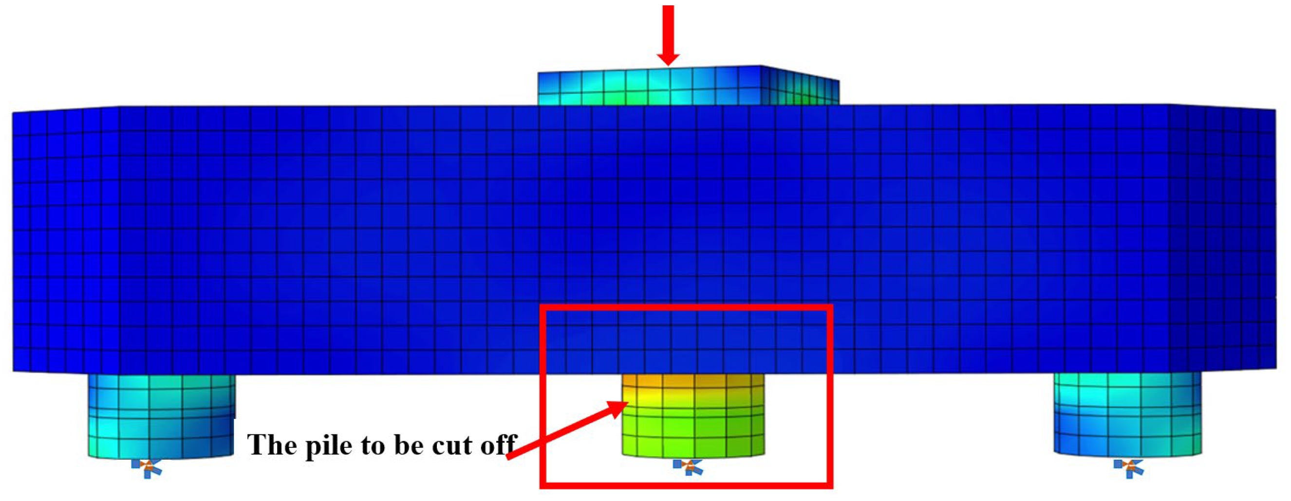
During active underpinning, the transfer of superstructure loads from the existing foundation to the underpinning beam is often instantaneous [14]. A finite element model of the underpinning beam was developed to simulate the pile cutting process, aiming to clarify the stress, strain, and displacement variations in the beam during load transfer.
To reduce computation time, additional considerations were made. The additional piles are designed as end-bearing piles. The self-weight of the upper bridge and vehicle loads were calculated in accordance with specifications. These loads were distributed to the two piers during modeling. The model only includes beams and pile foundations, without considering the influence of soil layers. Abaqus/CAE 2022 software was used for finite element modeling and analysis. Specifically, the bottom of the pile foundation was fixed with constraints, and adaptive meshing was adopted. Beams were simulated using solid elements, and piles were also simulated with solid elements. The reserved mudstone columns for pile bottom support were simulated using beam elements. Point loads were applied to the superstructure of the pile foundation. The calculation model is shown in Figure 4.
As shown in Figure 1, the bridge pier is a portal frame structure. This pile foundation underpinning project focuses solely on the bridge piles supporting Pier 1, while the superstructure remains asymmetric. Consequently, the vertical loads borne by Pier 1 and Pier 2 differ significantly. To address this, a finite element model of the superstructure was developed based on the pier structural diagrams provided by the designer. Load distribution analysis indicates that the total superstructure load is approximately 9780 kN, with Pier 1 supporting approximately 3520.8 kN and Pier 2 bearing approximately 6259.2 kN. Therefore, the vertical load applied to the pier column in Figure 4 is determined as 3520.8 kN.
Combined with the preliminary survey data and design drawings, the parameters of the structure are determined as shown in Table 1.

5. Comparison of Calculation Results with Monitoring Data

5.1. Strain Analysis

5.1.1. Finite Element Calculation

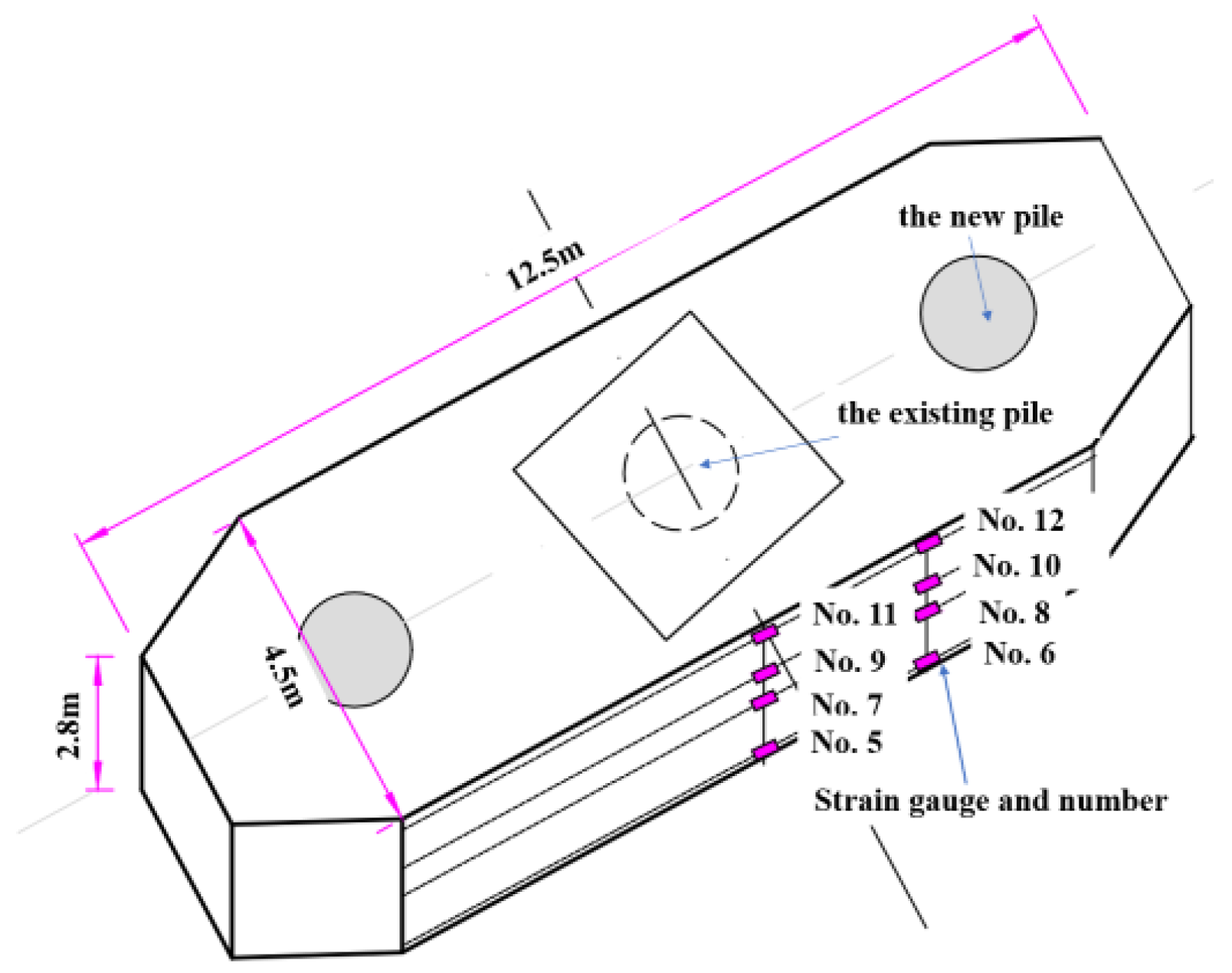
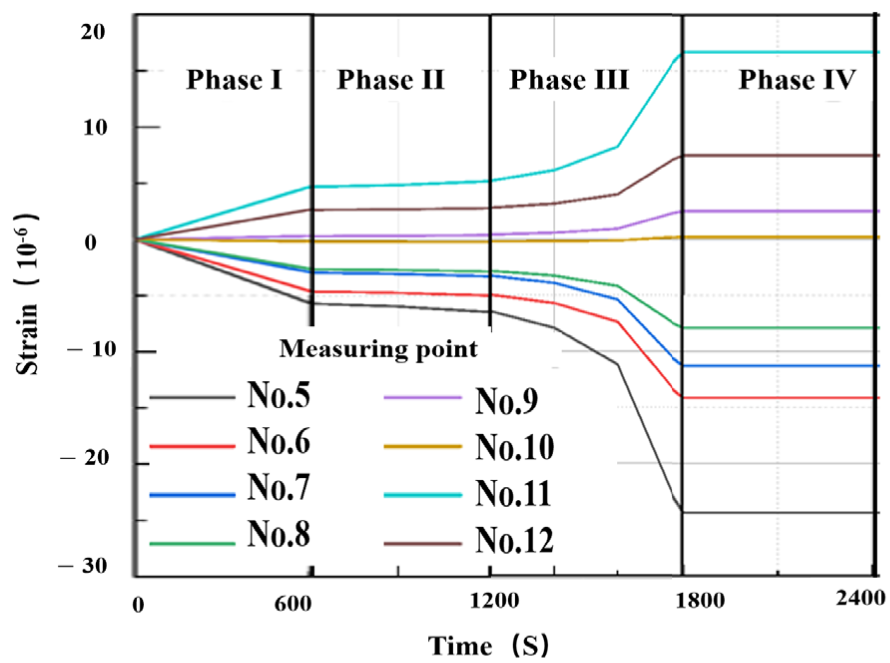
The model is established, and the stress calculation and analysis are carried out according to different stages. The arrangement of each measuring point is consistent with the actual monitoring point (Figure 5). Vibrating wire strain sensors are used in monitoring. The data calculation results are shown in Figure 6.
To validate the model, the measured data from monitoring points No. 5, No. 7, No. 9, and No. 11 in the first stage are first analyzed. It is required that the numerical calculation data and the on-site measured data should be within a 10% margin; otherwise, the model shall be adjusted until the requirement is met.
Analysis of Figure 6 indicates that the force transformation process of the underpinning beam can be roughly divided into four stages. The pile cutting process is divided into four stages, each with a duration of 60 min, resulting in a total time of 4 h. Among all measurement points, the tensile strain variation at No. 5 point is the most significant, reaching −24.3 × 10⁻⁶, located on the main reinforcement at the bottom of the side beam near the existing pile cap. The largest compressive strain variation occurs at Point 11, measuring 17.1 × 10⁻⁶, situated on the main reinforcement at the top of the side beam near the existing pile cap.
Stage 1: All measurement points exhibit relatively rapid strain variation rates.
Stage 2: The strain variation rate at each point decreases significantly.
Stage 3: The strain variation rate peaks, particularly for compressive strains. At this stage, the tensile strain at Point 5 constitutes approximately 70% of the total strain, while the compressive strain at Point 11 accounts for roughly 57% of the total strain.
Stage 4: Strains at all measurement points stabilize after the completion of the pile cutting process.

5.1.2. Comparison of Calculated and Measured Data

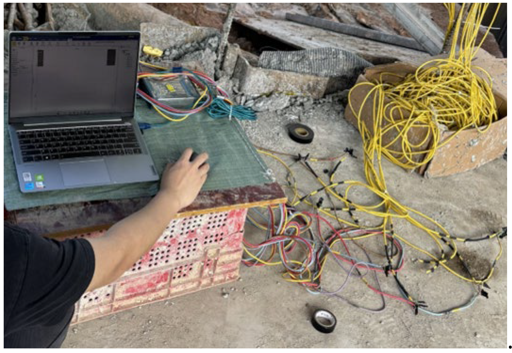
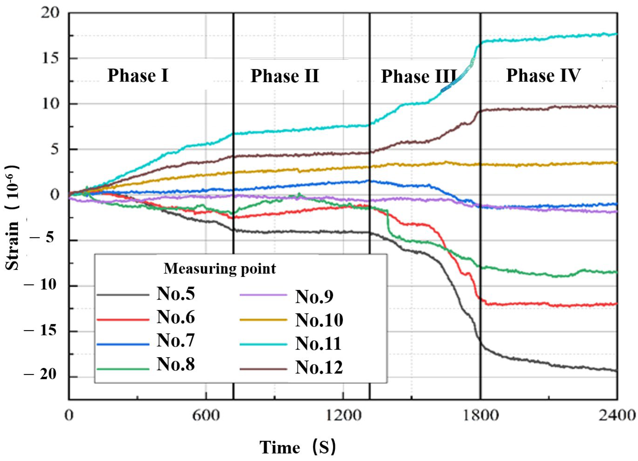
The strain measuring points during monitoring are arranged on the stressed steel bars, Figure 7 is strain on-site monitoring and the measured data of each strain point are shown in Figure 8. For comparison, the measured strain curves of the measuring points are also divided into four stages. It can be seen from the comparison of Figure 6 and Figure 8 that the numerical simulation results are in good agreement with the actual monitoring data on site, and the stress-strain changes in the pile cutting process simulated by the software also show a trend of “first fast, then slow, then urgent, and finally fast stabilizing”, which generally shows the reliability of the calculation model; No. 5 measuring point and No. 11 measuring point are still the largest measuring points for tensile and compressive strain, and the strain at each measuring point has a small numerical deviation. Among them, the difference between No. 5 measuring point after the fourth stage is relatively large, with the measured value being 19.5 × 10⁻⁶ and the calculated value being 24.3 × 10⁻⁶, and the measured value is about 80% of the calculated value. An analysis of the cause suggests that the effect of the stratum was not considered in the calculation, while the measured value is subject to the support of the foundation, resulting in a smaller decrease.

5.2. Settlement Analysis

5.2.1. Vertical Deformation Calculation

In the finite element analysis, as the primary focus is on the underpinning beam, the three-dimensional displacements of the new piles and the existing pile tips are constrained during modeling. The self-weight load of the underpinning beam is first applied, followed by the superstructure load on the existing pile cap. The load value is consistent with the total load transferred from the superstructure to the underpinning beam.
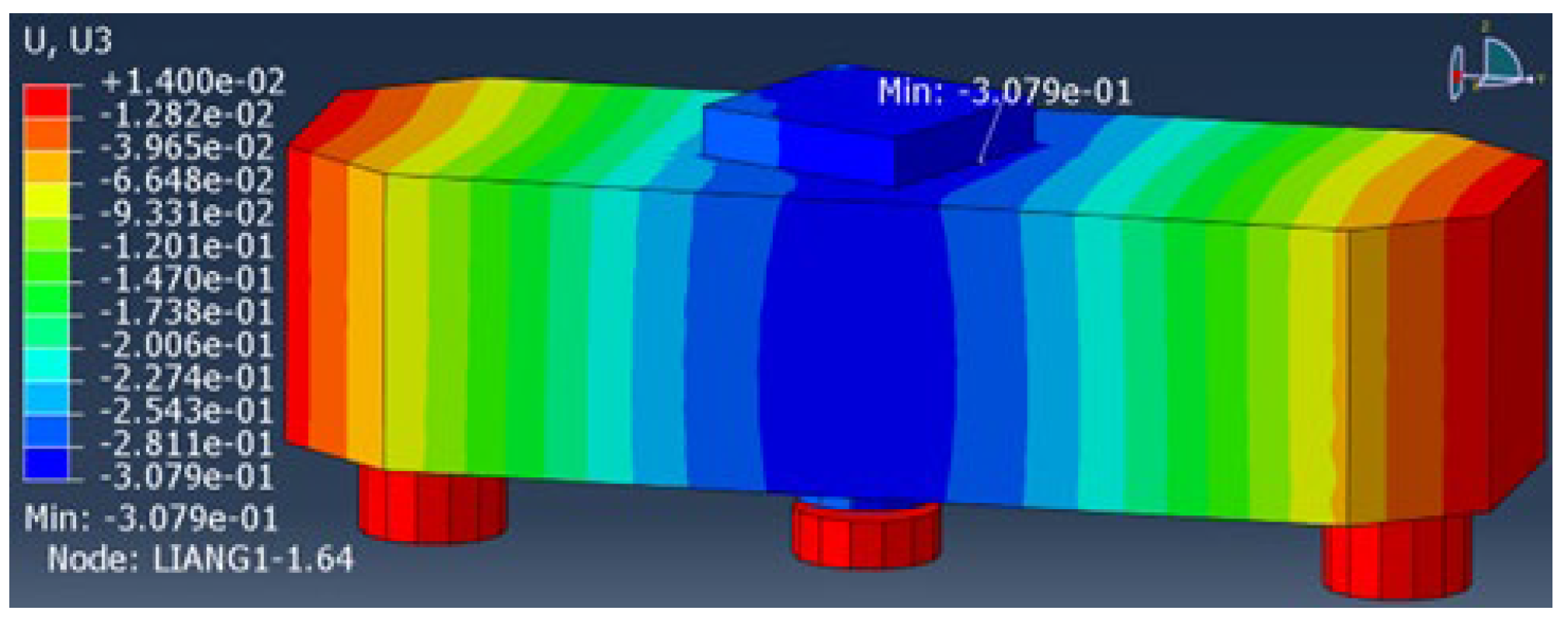
Using the “live-dead element” technique, the existing pile cutting elements are deactivated in five stages until the existing piles are completely disengaged from the underpinning beam [15]. Figure 9 illustrates the vertical displacement contour plot after completion of pile cutting. The results indicate that the maximum displacement at the top of the underpinning beam is approximately 0.31 mm, which meets the requirement specified in the design document that the displacement shall not exceed 1 mm.

5.2.2. Calculation and Measurement Comparison

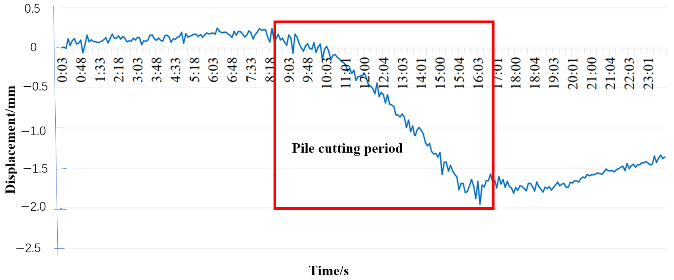
During the construction period of pile foundation underpinning from 13 October 2023 to 11 June 2024, a static leveling inclinometer was used to monitor the bottom of the beam in real time (once every five minutes) throughout the process, and the safety of the construction process was ensured by setting early warning values. Similarly, high-precision static leveling was used at the construction site, and the maximum relative settlement of the bottom of the pier was less than 1 mm, which was consistent with the finite element calculation results.
The change curve measured by the fully automatic monitoring platform is shown in Figure 10. It can be seen from the figure that the deformation of the front section is relatively stable and close to 0, indicating that the pile is not cut; the middle section, 8:18–16:03, is the pile cutting process. As the pile is cut off, the maximum relative settlement of the bridge beam bottom changes from 0 mm to 1.9 mm, and the displacement changes rapidly; the displacement change of the rear section becomes smooth and stabilizes. According to the construction data, the pile cutting on that day starts from 8:00 to 12:00, and the process takes about 4 h, but the settlement change of the bridge takes about 6 h. It can be seen that the settlement change is a relatively slow change process, which is related to the force transmission process of beams, piers, and bridges, especially the stress change of the underpinning beam. This is related to the force transfer process of the bridge (pile cutting—beam—pier/new pile—bridge deck), and is particularly closely associated with the stress variation of the underpinning beam.

6. Discussion

6.1. Displacement Control Value of Superstructure

To ensure the normal operation of the viaduct and surrounding facilities, vertical displacement control of the bridge superstructure is of utmost importance [16]. Excessive displacement may compromise traffic safety, while excessively small displacement could lead to increased size and stiffness of underpinning beams, resulting in higher costs.
According to Clause 5.3.3 of the Code for Design of Foundation and Subgrade of Highway Bridge Culverts [17], the settlement of the platform shall adhere to the following provision: the differential settlement between adjacent piers (excluding construction settlement) shall not cause the bridge deck to form an additional slope (fold angle) greater than 2°. Assuming a bridge deck width of 15 m, this corresponds to a settlement value of 3 mm. In this paper, the maximum value of on-site monitoring is 1.9 mm. Therefore, comprehensively considering the traffic conditions of the bridge and the requirements for additional stress, it is indicated that it is reasonable to recommend the actual settlement to be 3 mm.

6.2. Determination of Jacking Force

One of the purposes of applying jacking load is to make the axial force of the original foundation pile zero and no longer bear the load of the superstructure [18]. At this time, the original foundation pile withdraws from work, which is the best time to cut the pile. The second is to apply a jacking load, which can preload the underpinning foundation pile and eliminate most of the settlement, so that the deformation of the superstructure of the bridge after the underpinning is completed is minimal.
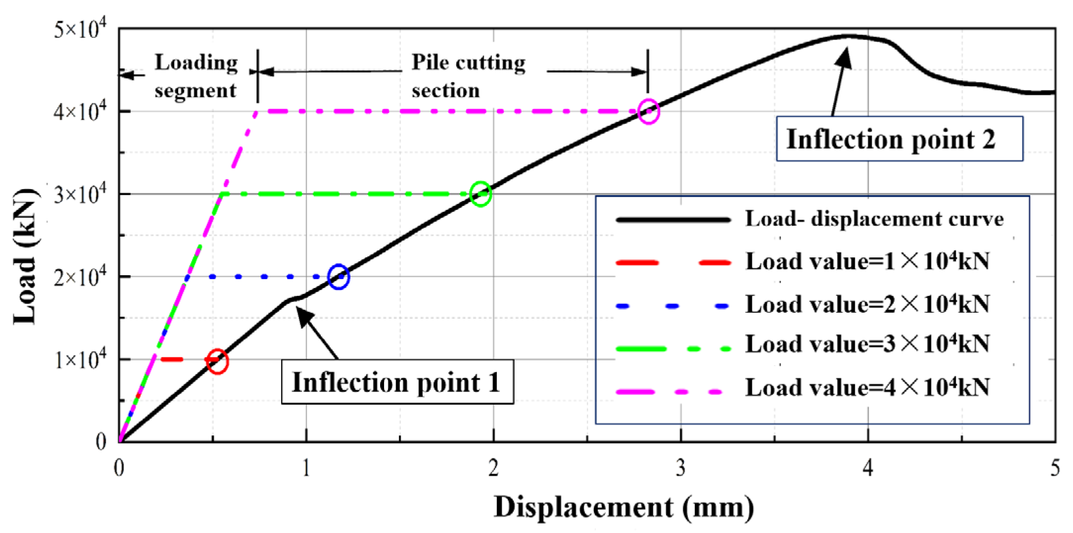
In this paper, we firstly apply 1 × 10⁴ kN, 2 × 10⁴ kN, 3 × 10⁴ kN, and 4 × 10⁴ kN loads to the top of the existing pile caps in the model, and then cut off the existing piles at the bottom, and obtain the load-deformation relationship of different processes. For comparison, the load-displacement curves of the simply supported beam (without considering the force of the old pile) are obtained by applying displacement loads on the top of the existing pile caps. The load-deformation curves of the underpinning beams under different loads are shown in Figure 11.
After analyzing Figure 11, it can be seen that the specimens with L/D ratios of 3 and 4 show more pronounced falling sections, followed by two rising sections, which can be categorized as Type II curves. In contrast, the specimens with an L/D ratio of 2 exhibit a more gradual descent after reaching the peak, without obvious falling and strengthening sections, and can be classified as Type I curves. Comparing specimens it can be seen from the figure that when different loads are applied, the deformation curves of each load appear as bifold lines, and the underpinning beam has greater stiffness in the loading section because the bottom pile is not cut off at this time; during the process of pile cutting, the upper load remains unchanged, and the displacement develops rapidly.
The load-displacement curve of the simply supported underpinning beam under displacement loading indicates that before the applied displacement is 4 mm, the curve shows an upward trend, but after the displacement exceeds 4 mm, the force decreases; before the inflection point 1, the underpinning beam is in an elastic force state. Between the inflection point 1 and the inflection point 2, the underpinning beam is in a working stage with cracks. After the inflection point 2, some of the steel bars of the underpinning beam yield, resulting in a decrease in the bearing capacity.
Therefore, the determination of the jacking force should comprehensively consider three factors: to ensure that the axial force of the original foundation pile is zero; to eliminate most of the settlement, so that the deformation of the superstructure of the bridge after the underpinning is completed is minimal; to ensure that the steel stress of the underpinning beam is less than the allowable value and does not yield.
Based on the above factors, it is recommended that the jacking force be greater than the load value transmitted from the pier column to the underpinning beam, and less than 75% of the maximum bearing capacity. This project is handled according to this method, and 3600 kN is taken. The implementation effect and monitoring data show that the value is more reasonable, and it also shows that the design of the underpinning beam is more reasonable.

7. Conclusions

This study is based on the design and construction scheme. It also incorporates on-site monitored stress and displacement data. A three-dimensional finite element simulation model is established. This model targets the active pile foundation underpinning project of the subway tunnel crossing under the bridge. It analyzes the distribution and variation laws of stress and settlement during the pile foundation underpinning process, and the main conclusions are as follows:
(1)
Aiming at the technical challenge of tunnel undercrossing bridges in complex geological conditions, a reasonable active pile foundation underpinning design scheme was proposed, considering terrain constraints and the requirement of uninterrupted bridge operation. The fundamental construction process was established. A three-dimensional numerical model simulating the active underpinning process was developed, and its validity was verified by comparing the computational results with experimental data.
(2)
Comparative analysis of strain data between numerical simulations and field measurements reveals a high degree of consistency. The strain evolution during pile cutting exhibits a characteristic pattern: “rapid initial change, followed by deceleration, then acceleration, and finally rapid stabilization”. Notably, after the fourth stage, the measured strain at No. 5 monitoring point (19.5 × 10⁻⁶) deviates from the computed value (24.3 × 10⁻⁶), with the measured value being approximately 80% of the numerical prediction.
(3)
Comparison between numerical predictions and static leveling measurements indicates that the maximum relative settlement at the pier base is less than 1 mm, which is consistent with the finite element calculation results. The pile cutting leads to inconsistency between the deformation of the underpinning beam and the settlement of the bridge, with the settlement variation of the bridge being relatively slow.
(4)
Taking into account the traffic conditions of the bridge and the requirements for additional stress, it is reasonable to recommend that the actual settlement of the active pile foundation underpinning of the bridge be 2–3 mm. The jacking force should generally be determined with two criteria. It should be greater than the load transferred from the pier column to the underpinning beam. It should also be less than 75% of the maximum bearing capacity.

Author Contributions

Conceptualization, Z.X. and X.T.; methodology, Z.X. and L.L.; software, L.L.; validation, X.T.; formal analysis, Z.X. and B.Y.; investigation, Z.X. and B.Y.; resources, B.Y.; data curation, L.L. and X.T.; writing—original draft preparation, B.Y. and X.T.; writing—review and editing, Z.X. and B.Y.; visualization, L.L.; supervision, X.T.; project administration, Z.X.; funding acquisition, Z.X. and X.T. All authors have read and agreed to the published version of the manuscript.

Funding

This research was funded by the Research Work of Guangdong construction engineering group holding Co., Ltd. (Grant No. JGLX2022004); the Research Work of Guangdong construction engineering architectural group Co., Ltd. (Grant No. JK2022RD02); the National Natural Science Foundation of China (Grant No. 42067044); the National College Student Innovation Training Program (Grant No. 202410595135).

Data Availability Statement

The data used to support the findings of this study are available from the corresponding author upon request.

Conflicts of Interest

Author Lian Liu was employed by the company Guangdong Jianke Architectural Design Institute Co., Ltd. The remaining authors declare that the research was conducted in the absence of any commercial or financial relationships that could be construed as a potential conflict of interest. The authors declare that this study received funding from Guangdong construction engineering group holding Co., Ltd. The funder was not involved in the study design, collection, analysis, interpretation of data, the writing of this article or the decision to submit it for publication.

References

  1. Peng, F.; Qiao, Y.; Dong, Y.; Run, Z.; Zhu, H. Development Strategy for Urban Underground Space in the New Development Stage. China Eng. Sci. 2024, 26, 176–185. [Google Scholar]
  2. Wang, W.; Yao, J.; Yue, J.; Lan, W. Key techniques and application of underground space development under neath heritage buildings in soft soil. J. Build. Struct. 2023, 44, 92–99. [Google Scholar]
  3. Chen, J.; Shang, H.; Xu, S. Comparative Analysis and Research on the Construction Scheme of the Entrance and Exit line of Yuzhu Depot Passing under Building Complex. Mod. Tunneling Technol. 2022, 59 (Suppl. S1), 776–782. [Google Scholar]
  4. Zhang, T.; Hu, C.; Zhou, S.; Wei, J.; Wang, Q. Key technology of pile foundation underpinning design for BRT bridge under tunnel. Highway 2022, 67, 43–50. [Google Scholar]
  5. Liang, Y.; Zhai, L.; Shi, H. Research and Application of Arch-shaped Pile Foundation Underpinning in Tunnel with Large Axial Force and Span of Metro Construction. Tunn. Constr. 2020, 40, 1765. [Google Scholar]
  6. Huang, S.; Liu, J.; Tian, W. Research on Underpinning and Deformation Control of Pile Foundation in Tunnel under Bridge. J. Railw. Eng. Soc. 2023, 40, 9–14. [Google Scholar]
  7. Sheng, H.; Li, H.; Gu, X.; Jin, W. Researches on the mechanical properties and deformation characteristics of the temporary support system of pile foundation underpinning. Build. Struct. 2021, 51 (Suppl. S2), 1545–1550. [Google Scholar]
  8. Chen, X.; Zhang, X.; Zhao, Y.; Liu, J.; Yu, W.; Zhou, X.; Dong, Z. Study on the influence of the in-tunnel underpinning construction of the subway tunnel in the soft ground on the pile foundation. J. Railw. Sci. Eng. 2021, 18, 3294–3302. [Google Scholar]
  9. Zhang, P.; Sun, G.; Liu, H.; Yuan, W. Research on mechanical behavior and deformation law of pile foundation underpinning of special shaped slab bridge. Chin. J. Appl. Mech. 2024, 41, 843–852. [Google Scholar]
  10. Lv, W. Model test and numerical simulation of under pinning pile foundation in saturated loess arca. Railw. Eng. 2022, 62, 94–97. [Google Scholar]
  11. Li, H.; Wang, C. Simulation Evaluation Method for Reinforcement Effect of Active Underpinning of Tunnel Pile Foundation. Comput. Simul. 2021, 38, 188–192. [Google Scholar]
  12. Yang, Z.; Duan, J.; Guo, Q.; Yan, Y. Deformation Monitoring Analysis of Pile Foundation Underpinning of Irregular Widening Continuous Beam. Urban Mass Transit 2022, 25, 106–111. [Google Scholar]
  13. Zang, Y.; Liu, C.; Yan, J.; Yu, J.; Yu, T.; Zhu, H.; Ding, P.; Zhu, J.; Xu, R. Study on the influence and control methods of shield tunneling through the existing buildings. Build. Struct. 2023, 53 (Suppl. S1), 2960–2964. [Google Scholar]
  14. Lin, L. Stress System Transform of Operational BRT Viaduct Piles Underpinned by Cast-in-Situ Tunnel Structure of Xiamen 2nd East Passage. Tunn. Constr. 2023, 43, 1896. [Google Scholar]
  15. Li, S. Abaqus Finite Element Analysis: From Entry to Mastery (2022 Edition); China Machine Press: Beijing, China, 2022. [Google Scholar]
  16. Liu, L.; Xiao, X. Research on deformation control technology of shield tunnel penetrating existing railway. Low Temp. Build. Technol. 2023, 45, 109–112. [Google Scholar]
  17. JTG 3363—2019; The Ministry of Transport of the People’s Republic of China. Specifications for Design of Foundation of Highway Bridges and Culverts. China Communications Press: Beijing, China, 2019.
  18. Lin, G.; Ke, W.; Guo, S.; Lin, Z.; Xu, C.; Chi, M.; Xiao, Y. Influence of Pile Foundation Construction on Existing Tunnels in a Metro Protection Area: Field Test and Numerical Simulation. Buildings 2024, 14, 2280. [Google Scholar] [CrossRef]
Figure 1. Conflict between tunnel and pile foundation (unit: m).
Buildings 15 03034 g001
Figure 2. Supporting design scheme (unit: m).
Buildings 15 03034 g002
Figure 3. Construction process.
Buildings 15 03034 g003
Figure 4. Numerical model of supporting structure.
Buildings 15 03034 g004
Figure 5. Strain monitoring point arrangement.
Buildings 15 03034 g005
Figure 6. Calculated value of each measuring point.
Buildings 15 03034 g006
Figure 7. Strain on-site monitoring.
Buildings 15 03034 g007
Figure 8. Measured value of each measuring point.
Buildings 15 03034 g008
Figure 9. Vertical displacement through the underpinning structure.
Buildings 15 03034 g009
Figure 10. Relative settlement of the beam bottom.
Buildings 15 03034 g010
Figure 11. Load-deformation curve.
Buildings 15 03034 g011
Table 1. Numerical model material parameters.
Material NameMaterial GradeModulus of Elasticity E/GPaPoisson’s Ratio μDensity γ/(kN∗m−3)
Main tendonHRB4002100.378.0
StirrupHPB3002100.378.0
Foundation pit cushionC2025.50.224.0
Existing piers, caps and pilesC3030.00.224.0
Underpinning pileC3531.50.224.0
Disclaimer/Publisher’s Note: The statements, opinions and data contained in all publications are solely those of the individual author(s) and contributor(s) and not of MDPI and/or the editor(s). MDPI and/or the editor(s) disclaim responsibility for any injury to people or property resulting from any ideas, methods, instructions or products referred to in the content.