1. Introduction
Architectural Heritage, as a vital component of cultural heritage, is an expression of history and helps us understand the relevance of the past to contemporary life. It constitutes a capital of irreplaceable spiritual, cultural, social, and economic value. An essential part of a community’s identity that should be passed on to future generations as a part of historical memory.
Documentation is the fundamental tool for recording, analyzing, and understanding all types of constructions of the built environment. The first and most necessary stage for the evaluation, restoration, preservation, and “comprehensive” protection of the architectural heritage in the present and in the future. It is also foreseen in the Venice Charter, approved already 60 years ago [
1].
The geometric documentation of monuments has always required special attention, diligence, and precision, both during the measurement procedure and during processing and drawing. The complexity of each monument, combined with the characteristics of the surrounding space, has created the need for advanced equipment and modern measurement and processing techniques.
Whether in the past, with the use of reflectorless total stations, or today with Terrestrial Laser Scanners (TLS) and Unmanned Aerial Vehicles (UAVs), topographic equipment has become indispensable for monument documentation. The evolution of technology and informatics has inevitably affected documentation procedures. Today, equal or even higher levels of precision can be achieved with significantly less effort in terms of time, costs, and personnel.
This paper presents a comparison of the geometric documentation of the same monument over a time span of more than 20 years. The subject is the Katholikon of the Holy Monastery of Daphni. A comparative analysis is provided between two projects. The first project was initiated in December 1999, after the earthquake of the 7th of September 1999, which left in its wake dozens of dead, collapsed buildings, and severe damage. The documentation was carried out as a sequence of actions for the protection of the monument [
2,
3]. The second project was carried out in June 2023, as part of a diploma thesis [
4]. In both cases, the most modern available equipment was used.
This study offers a comprehensive comparative analysis between two documentation campaigns of the same monument, 24 years apart. It contributes to the field by quantifying the impact of technological evolution on documentation efficiency, detailing the workflow transformation from traditional to digital methods, and offering insights into how such practices affect monument restoration strategies.
Furthermore, detailed geometric documentation of historical masonry constructions is a fundamental step to developing detailed finite element models for seismic assessment and strengthening of structures. There are many occasions that precise documentation supported restoration projects, like the seismic vulnerability assessment of masonry bell towers in South-East Lombardia [
5] or the seismic response evaluation of masonry churches in southern Italy [
6].
The paper is structured as follows:
Section 2 presents key historical and architectural facts about the monument.
Section 3 gives detailed information about the two different projects focusing on the equipment, the methodologies and the deliverables of each one.
Section 4 makes a comparison of the two projects, with the time and the equipment used being the critical factors of this comparison. Moreover, it attempts an approach to the changes that occurred through the restoration process, giving side-by-side comparisons of the damaged part and its corresponding restoration. Finally,
Section 5 discusses the produced results and provides the concluding remarks.
2. The Holy Monastery of Daphni—Historical Data and Architectural Features
The Holy Monastery of Daphni is a significant monument, known worldwide for its uniqueness and its architecture, and is also included in UNESCO’s World Heritage list. It is located at the western entrance of the Attica basin, on the outskirts of Mount Egaleo and dates back to the 11th century.
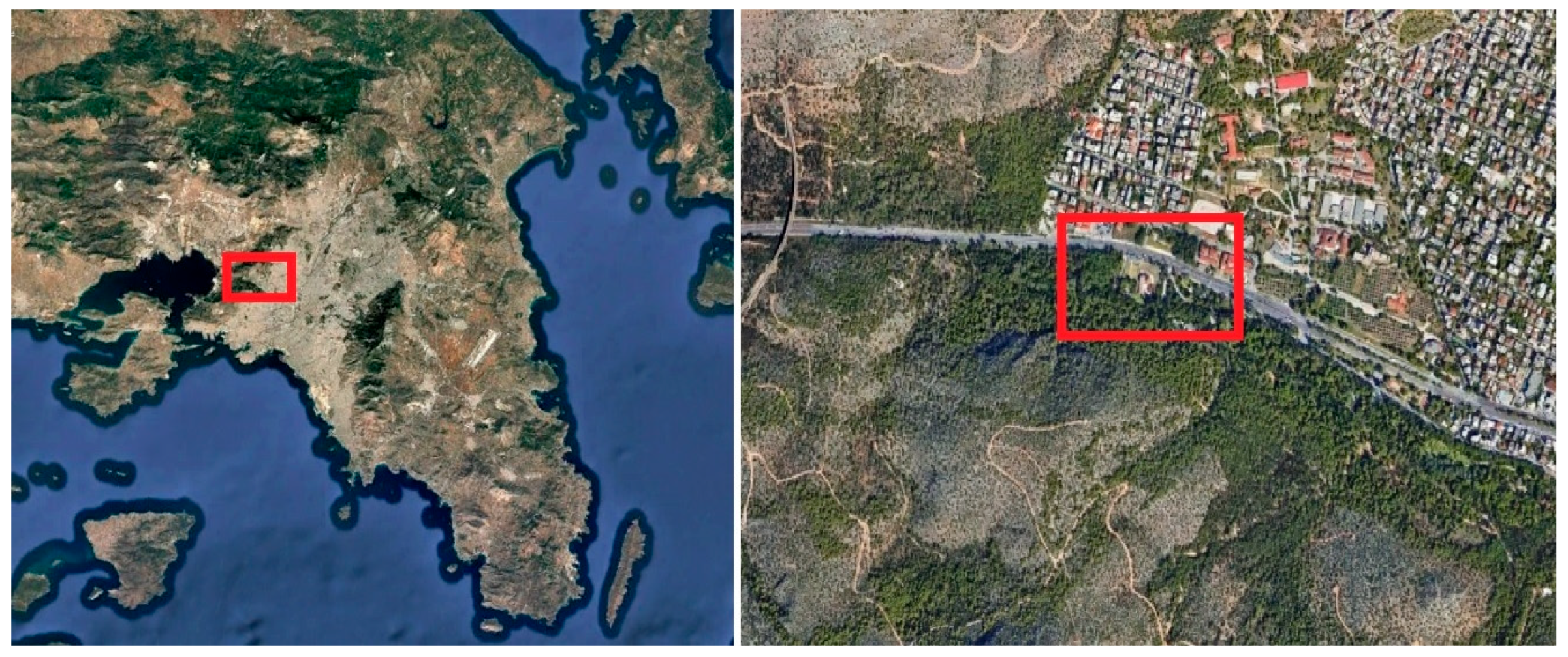
More specifically, the monastery is situated in the municipality of Haidari, approximately at the midpoint of the ancient Sacred Way, which once connected Athens with Eleusis and served as a processional route for the Eleusinian Mysteries (
Figure 1). The importance of the Monastery is also evidenced by its depiction on some of the earliest maps of the Attica region (
Figure 2).
Undoubtedly, the Holy Monastery of Daphni is the most important monument in Attica from the period of the great flourishing of Byzantine art. The site has played an important role in the development of the region since antiquity [
8]. Many researchers associate its name with Apollo Daphnaeus, whose sanctuary is believed to have stood at the same location. A column from the ancient sanctuary was used to support the arched openings on the southwestern side of the exonarthex and remains in place today. Lord Elgin removed three thin Ionic columns that supported the arched openings of the façade of the exonarthex of the monastery’s Katholikon.
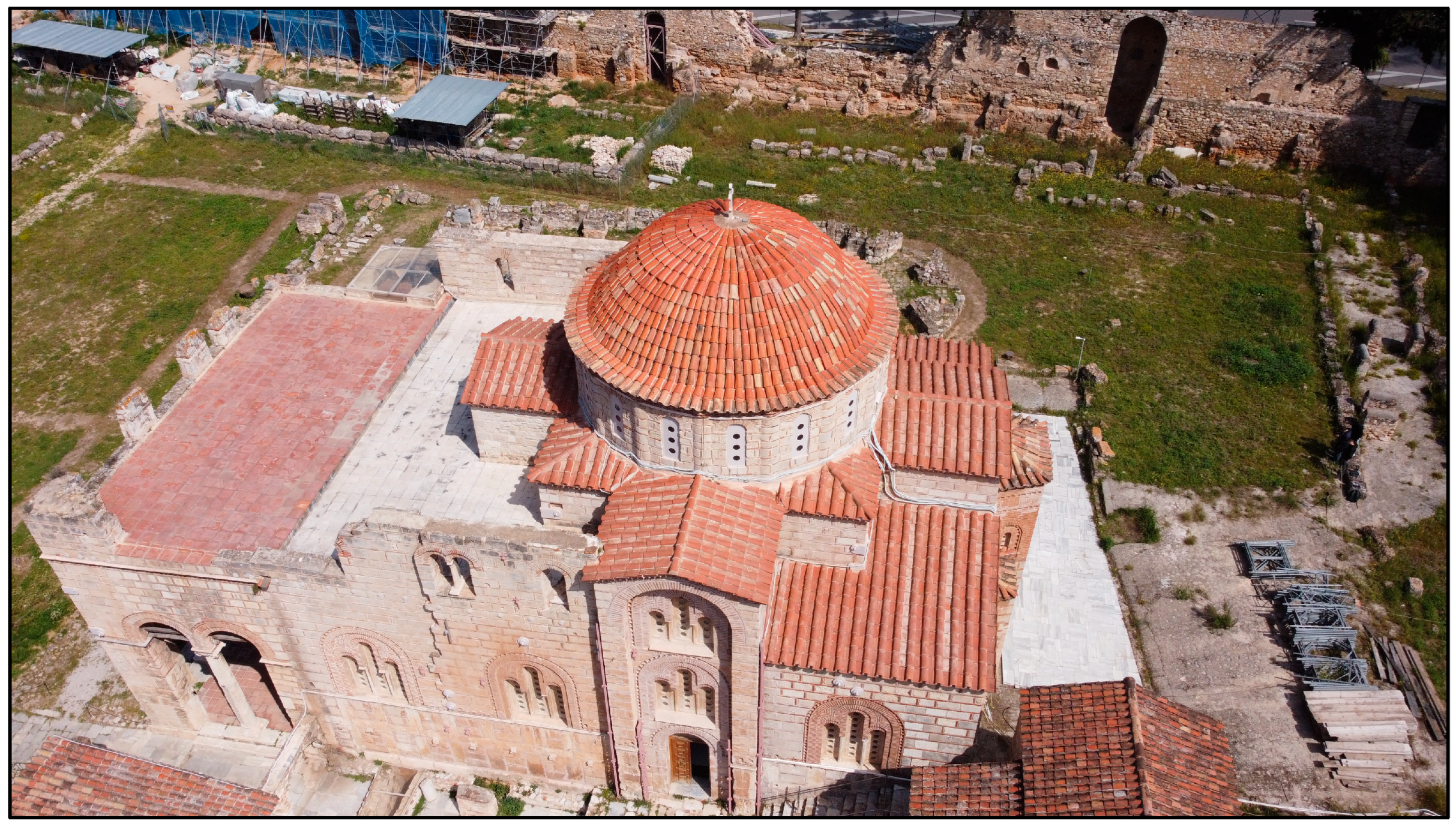
The Monastery is an illustrative example of Middle Byzantine architecture. In
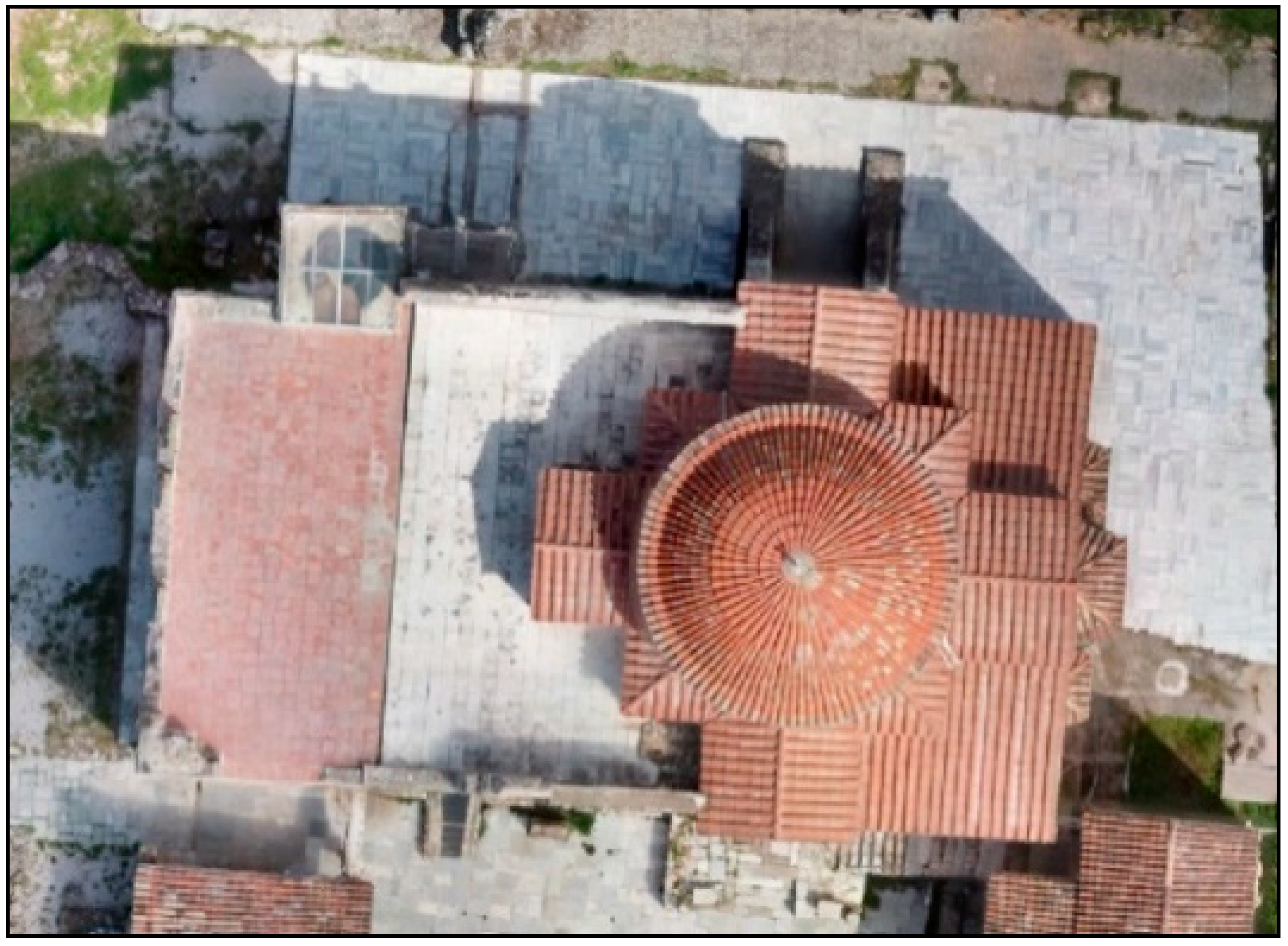
Figure 3, an aerial image that was taken in 2023 shows the current condition of the monument.
It is characterized by strict proportions, Doric simplicity on the exterior facades and clarity in the interior layout [
9]. The Katholikon follows the complex octagonal plan type. The main feature is the large dome, which spans nearly the entire width of the building. Its dome is of a sophisticated Constantinopolitan type, with sixteen windows [
10]. The term “octagonal” refers to the dome’s support system. This static solution has a pleasant aesthetic effect, as the central space of the church, formed under the dome, is undivided since it is not separated by internal supports [
11]. To the west is the inner narthex, a narrow and long space that communicates with the central space through arched openings. During the 12th century, an exonarthex was added to the west of the narthex, in the form of an open arcade with an upper floor.
Externally, the building ascends pyramidally to the dome, through a series of stepped roof sections. The mosaic decoration of the Daphni Monastery is among the monastery’s most remarkable features, which distinguishes it from other Byzantine Monasteries. The iconographic subjects reflect the doctrinal teaching of the church as it was created in the 11th and 12th centuries and follow the standards established in Constantinople after the end of Iconoclasm [
12]. There are 71 of them in total.
Despite the damage through the centuries due to human activity and natural phenomena, the splendor of the mosaics of the Katholikon has been preserved to this day. This is due to the particular style and technique used in their construction, as well as the excellent quality of the materials used [
13]. The Holy Monastery of Daphni was inscribed on the UNESCO World Heritage list in 1990, primarily because of these wonderful mosaics (
Figure 4).
3. Geometric Documentation of the Katholikon of the Monastery—Past and Present
On the 7th of September 1999, the Attica region suffered a severe earthquake. Among the buildings that were damaged was the Monastery of Daphni. The Ministry of Culture decided to take strong measures for the protection of the monument.
One of the first research programs for the protection and restoration was the geometric documentation of the monument. The other two research projects concerned:
- (i)
The preliminary survey of damages, assessment of mechanical properties of construction materials, monitoring of the width evolution of main cracks, and preparation of a first detailed computer model of the monument used for preliminary structural analyses;
- (ii)
The assessment of the physicochemical characteristics of the construction and pointing mortars [
13].
Most of the studies that followed used the deliverables of this geometric documentation in order to depict the historical pathology and past interventions of the monument [
14], to show where accelerometers and displacement transducers were placed [
15], and to illustrate the positions of radar paths and boroscopy holes [
16].
The restoration phases that followed were also based on this first geometric documentation [
17,
18].
3.1. Geometric Documentation After the Earthquake of 1999
The challenging and innovative geometric documentation project, under the title “Development of modern topographic and photogrammetric methods for the geometric documentation and architectural digital survey of Byzantine monuments with application to the Holy Monastery of Daphni”, was carried out by the Laboratory of Photogrammetry of NTUA as a research project of NTUA [
2].
Using state-of-the-art equipment of that era, after 2 years of hard work, the 2D geometric documentation drawings of the monument were produced, including, among others, the monument’s pathology. It was the first time that the Ministry of Culture required 2D drawings at a scale of 1:25 with colored orthophotos as official deliverables. Furthermore, all mosaics should be depicted in orthophotos at a scale of 1:5, and those on curved surfaces were foreseen to be unwrapped for accurate representation. All of the drawings should have an accuracy of 1:25 scale (i.e., ±7 mm). Additionally, the drawings were to show not only the geometry and the pathology of the monument but also the different structural materials.
A total of 17 scientists, most of them Surveying Engineers, participated in the project. The fieldwork covered approximately 30% of the total project duration.
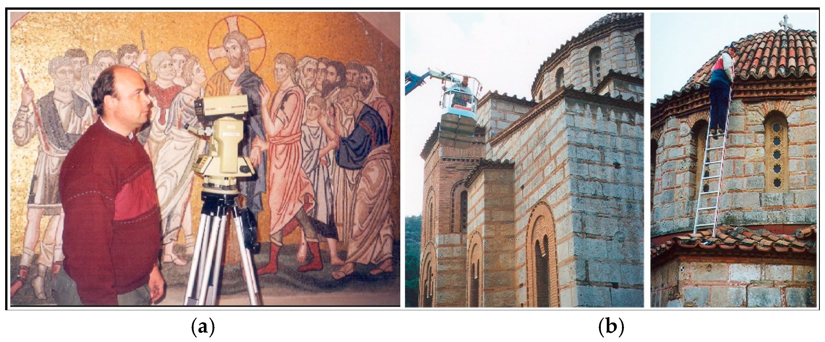
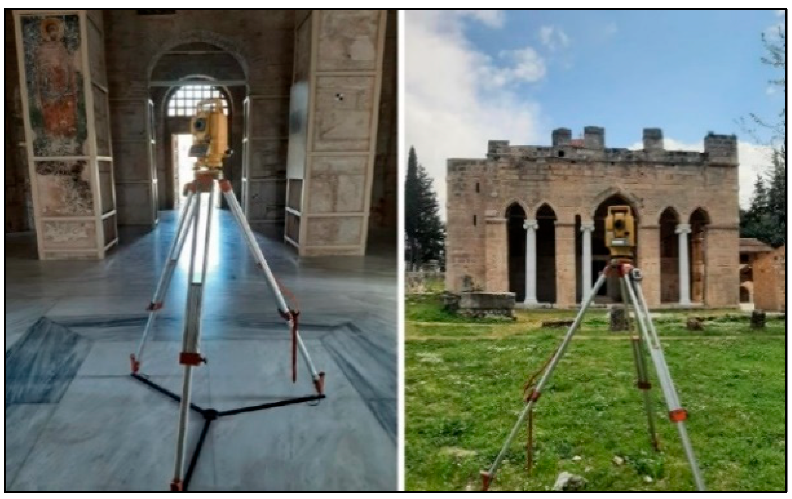
At that time, digital cameras, Terrestrial Laser Scanners (TLS) and UAVs practically did not exist or had not yet been applied for geodetic measurements. Therefore, a combination of traditional surveying and photogrammetric methods was used. The geodetic network consisting of 31 points located both inside and outside the Church was measured with a Leica TC 1600 total station. Each of the 11,500 detail points and GCPs was measured with a Distomat Dior 3002s EDM, which was the first ever reflectorless EDM, attached to the total station (
Figure 5a). The accuracy of the measured coordinates was estimated to ±3 mm [
19]. It should be noted that since this EDM was not coaxial with the total station’s telescope axis, rectification calculations were necessary to determine the correct slope distances.
As the deliverables were raster orthomosaics and vector drawings, there was a need for premarked GCPs on all parts of the monument, even on the most inaccessible ones (
Figure 5b).
The photogrammetric processing of the digitized analogue images was performed on a Z/I SSK digital photogrammetric workstation. Apart from the raw data of the survey, the deliverables were both vector and image products:
Horizontal sections at five different levels and a zenith view of the inside of the Katholikon roof (scales 1:25 and 1:50);
Four exterior façades (scale 1:25);
Ten longitudinal and ten cross-sections (scale 1:25);
Orthogonal image projections of all mosaics (scale 1:5);
Mathematical developments of the images of all mosaics situated on developable surfaces, and cartographic developments of the images of all mosaics situated on non-developable surfaces (scale 1:5);
A database built on a GIS philosophy, in order to interrelate all available information for all parts of the monument.
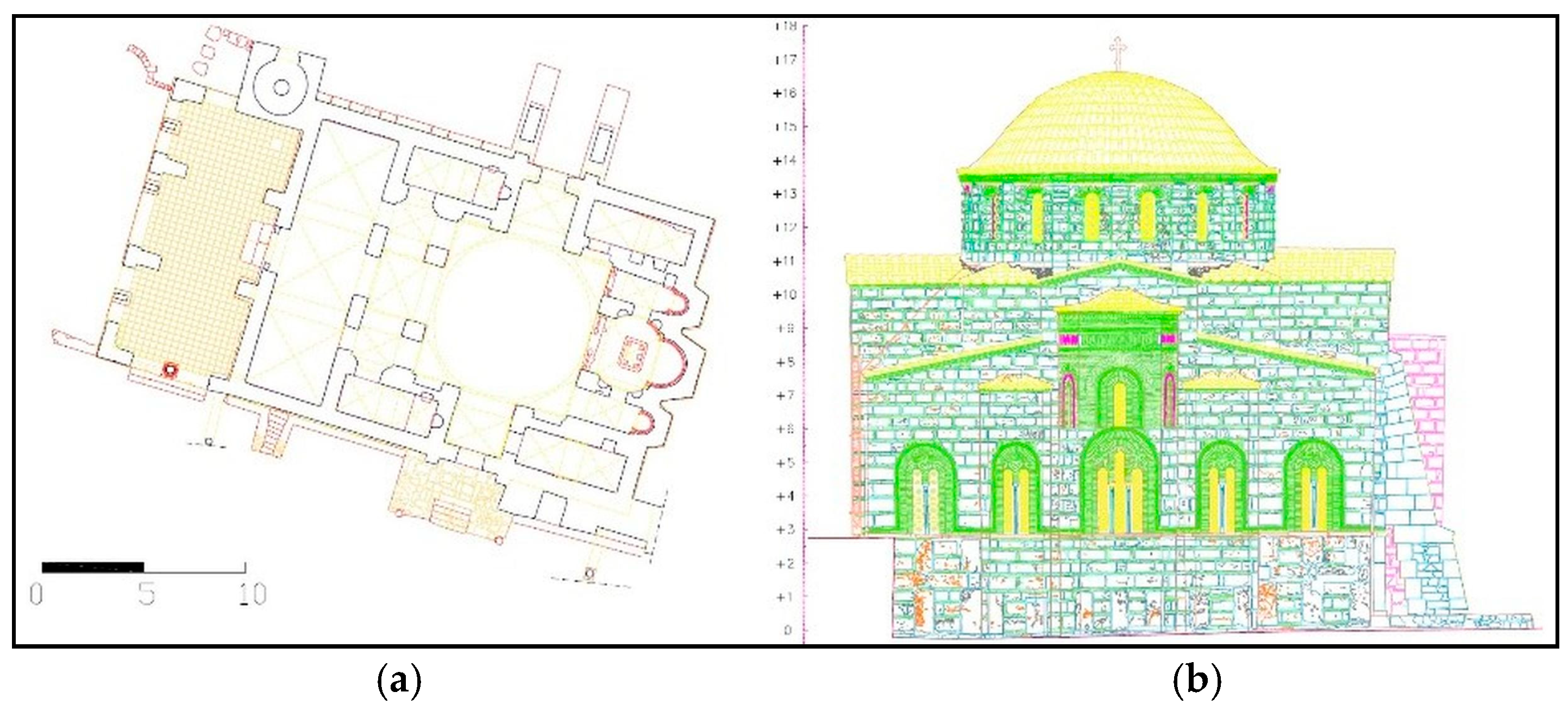
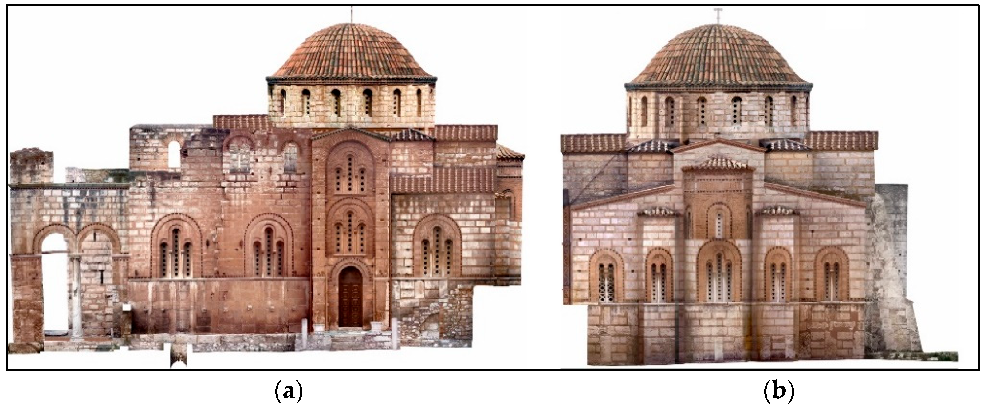
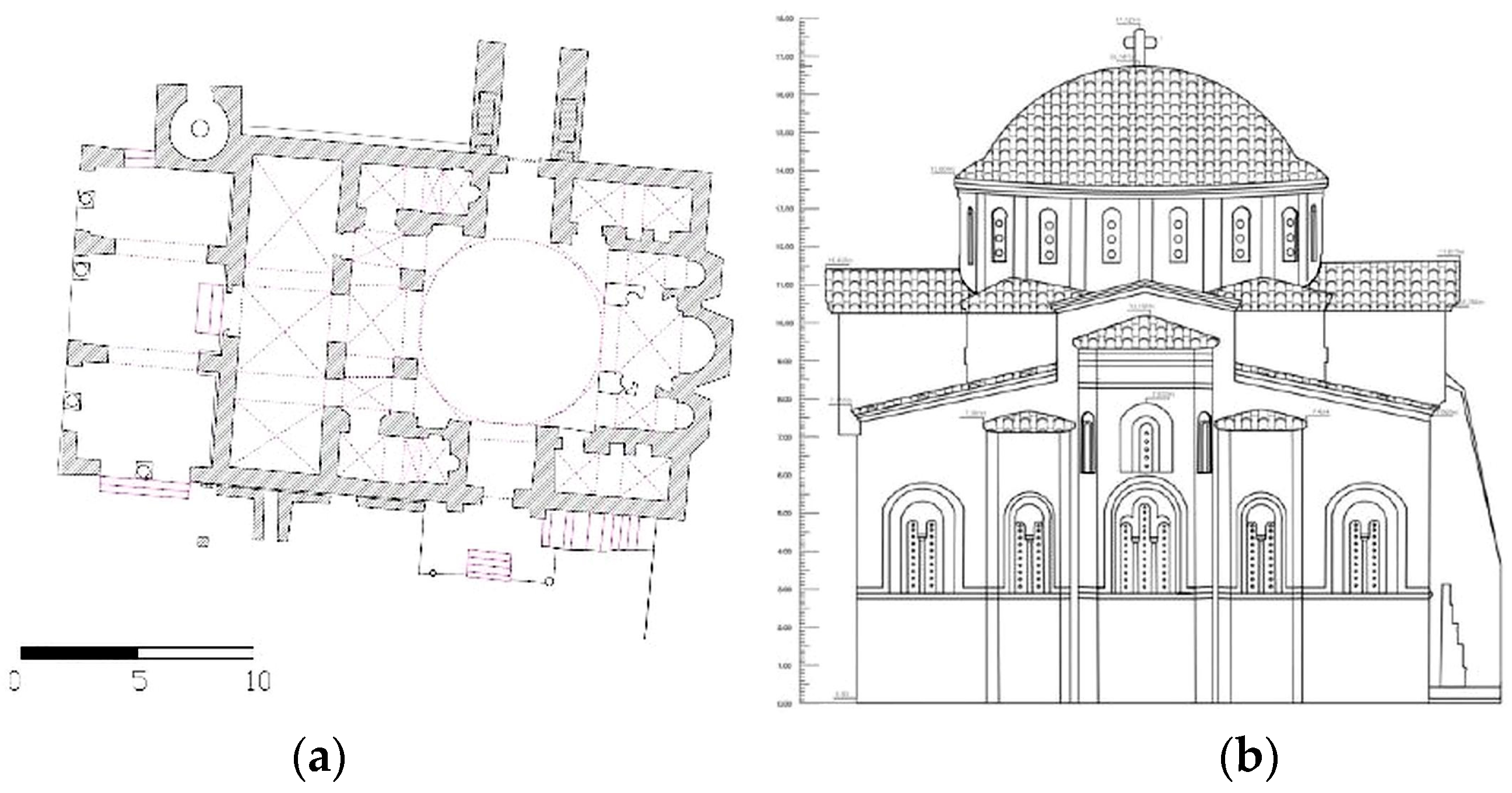
For all the above, both vector drawings (
Figure 6) and orthophotos (
Figure 7) were created. As mentioned, the monument’s pathology and the types of construction materials were also included in the drawings. The different colors and line weights used in the façade plans depict not only the pathology and different materials but also the different planes that are projected in the corresponding façade.
3.2. Geometric Documentation in 2023
In June 2023, for the needs of a diploma thesis [
4], the geometric documentation of the Katholikon of the Monastery was carried out 24 years after the aforementioned one. Many aspects had changed in the intervening years, in terms of equipment, procedures, software, time, and personnel involved. Although the purpose of this newer project differed significantly from that of the 1999–2001 effort, it also employed state-of-the-art equipment of its time.
In this project, a Terrestrial Laser Scanner was used for the documentation. Moreover, a UAV was used to document the inaccessible and non-visible areas, such as many parts of the dome and the roof. A reflectorless total station (Topcon GTS 3005, Topcon Corporation, Tokyo, Japan) was employed to measure the geodetic network, as well as the ground control points (GCPs). Additionally, a GNSS receiver (Trimble R8) was used at two points of the geodetic network. The GNSS measurements were used only for the orientation of the points and the orthometric height of one control point. The X and Y coordinates refer to a local coordinate system. Thus, with this method of georeferencing with minimum constraints, the adverse effect of the scale factor of the Greek reference system was avoided.
The geodetic network comprised only 8 points, as fewer GCPs were necessary and only a limited number of detail points were measured, which were used for cross-checking purposes (
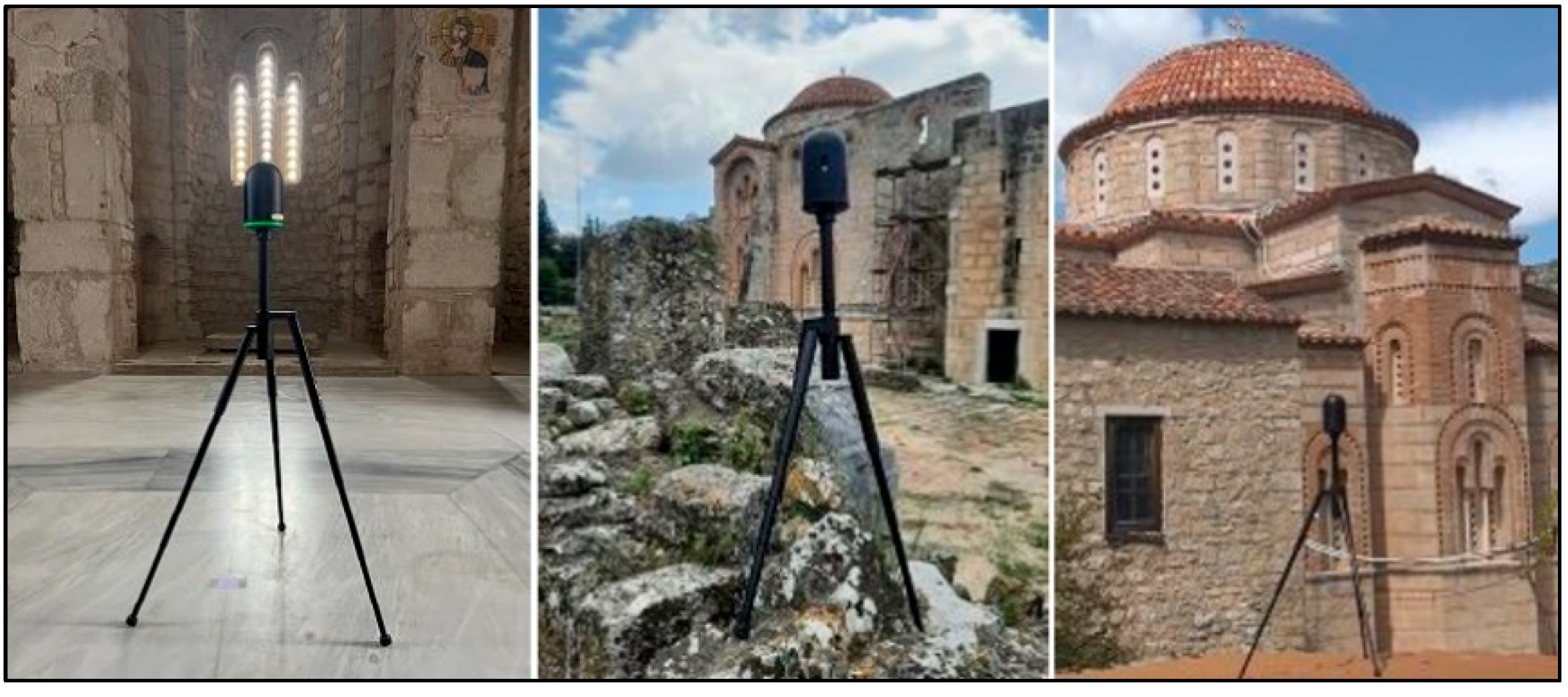
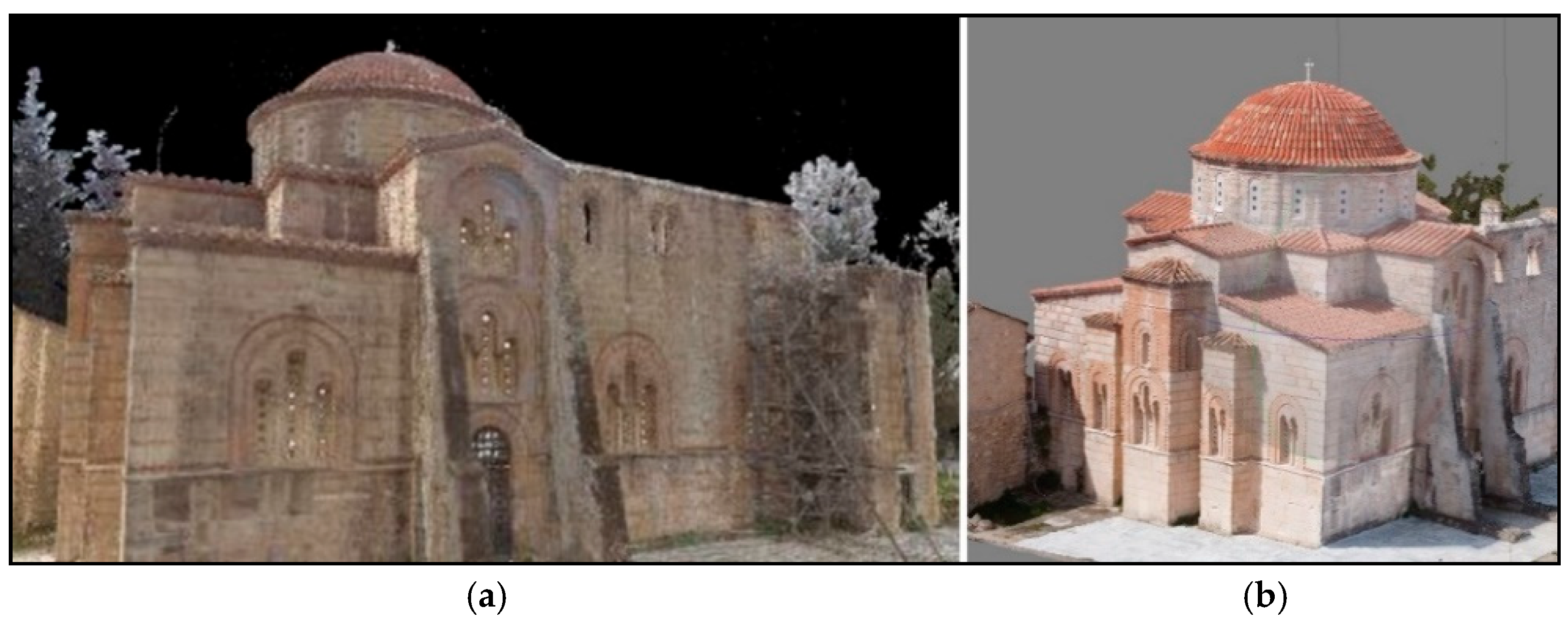
Figure 8). For data acquisition, a Leica BLK 360 G1 TLS (
Figure 9) and a DJI Mini 2 UAV were used. In total, 70 scan setups were initially performed, although 61 of them were used. The nine excluded setups consisted of one test scan, two problematic scans (people passing by in front of the TLS during the measurement procedure), and six scans that were very close to others and did not offer any additional information. Their removal helped reduce the final model’s size. Moreover, approx. 110 aerial images were taken during the project.
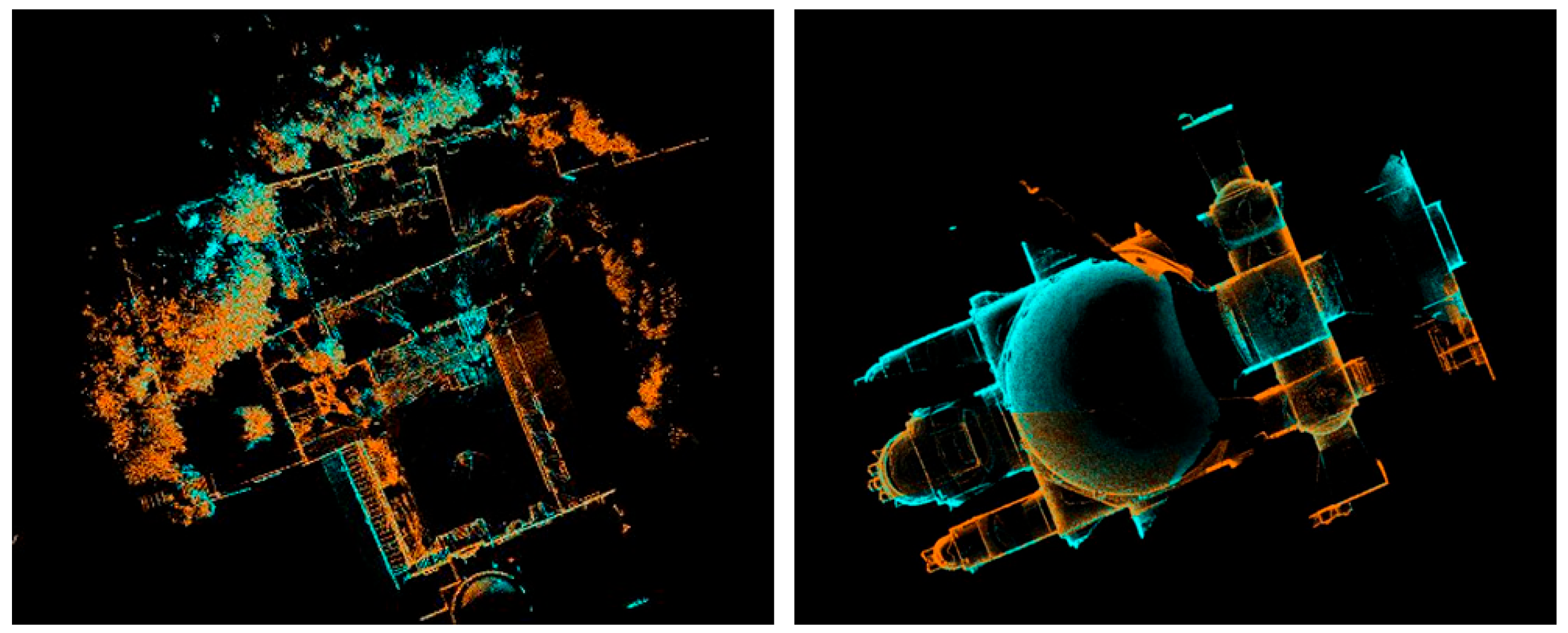
The registration of the point clouds and the UAV photos was performed using commercial software. TLS registration was conducted in Leica’s Cyclone Register 360 PLUS software (v. 2023.0.0) (
Figure 10).
The various TLS scans were successfully merged into a single, unified model. The overall 3D model achieved an accuracy of ±6 mm (
Figure 11).
The photogrammetric processing of UAV imagery was carried out using Agisoft Metashape (v. 2.0.3), which generated the point cloud from the images.
The deliverables of the project were the 3D model (
Figure 12), the floor plan, two façade plans (
Figure 13), and two cross sections and orthophotos (
Figure 14) of the Katholikon. All the aforementioned plans were produced at a scale of 1:50, while the pathology of the monument was not depicted on the drawings, as the scope of the 2023 project focused primarily on geometric representation rather than damage analysis or restoration planning.
4. A Comparative Approach
The two projects described were carried out for completely different purposes. The first, during the period 1999–2001, was carried out as a research program, funded by the Ministry of Culture, with deliverables produced at a scale of 1:25. The second, completed in 2023, was conducted as part of a diploma thesis, with deliverables at a scale of 1:50. As a result, the level of detail and the types of outputs were different and did not serve the same objectives.
A clear example of this difference is that in the 1999 project, the pathology of each individual brick was digitized and documented. The deliverables included façade drawings, horizontal sections at different heights, and vertical cross-sections at multiple positions. In contrast, although the 2023 project resulted in a complete 3D model of the monument, only selected drawings and orthophotos were produced from it.
A direct comparison between the two projects in terms of personnel, precision, and processing time is not appropriate. However, if the 1999 project were conducted today, it would likely follow the same methodology and use similar equipment as the 2023 project.
4.1. Measurement Methodologies
A precise geodetic network inside and around the Katholikon is essential in both cases. Both were measured with a total station. During the old project, the network was measured by applying the three (or more, where possible) tripod method. During the recent one, a mini prism was used. However, the need and the planning of the network are completely different for each case.
For the old project, photogrammetric and classical geodetic procedures were applied. So, there was a greater need for measuring GCPs on every single surface or plane. Moreover, thousands of characteristic points were measured with a total station. So, the geodetic network must have covered every part of the monument, even the narrowest spaces.
In contrast, the 2023 project was carried out with a TLS and a UAV. The need for the geodetic network was to measure GCPs for the registration of the point clouds and some checkpoints evenly distributed all around the monument. So, there was no need for so many station setups.
For the first case, 31 setups were implemented, whereas only eight were needed for the second one (
Figure 15). It goes without saying that the measurement of the geodetic network has increased dramatically the time needed for the field measurements.
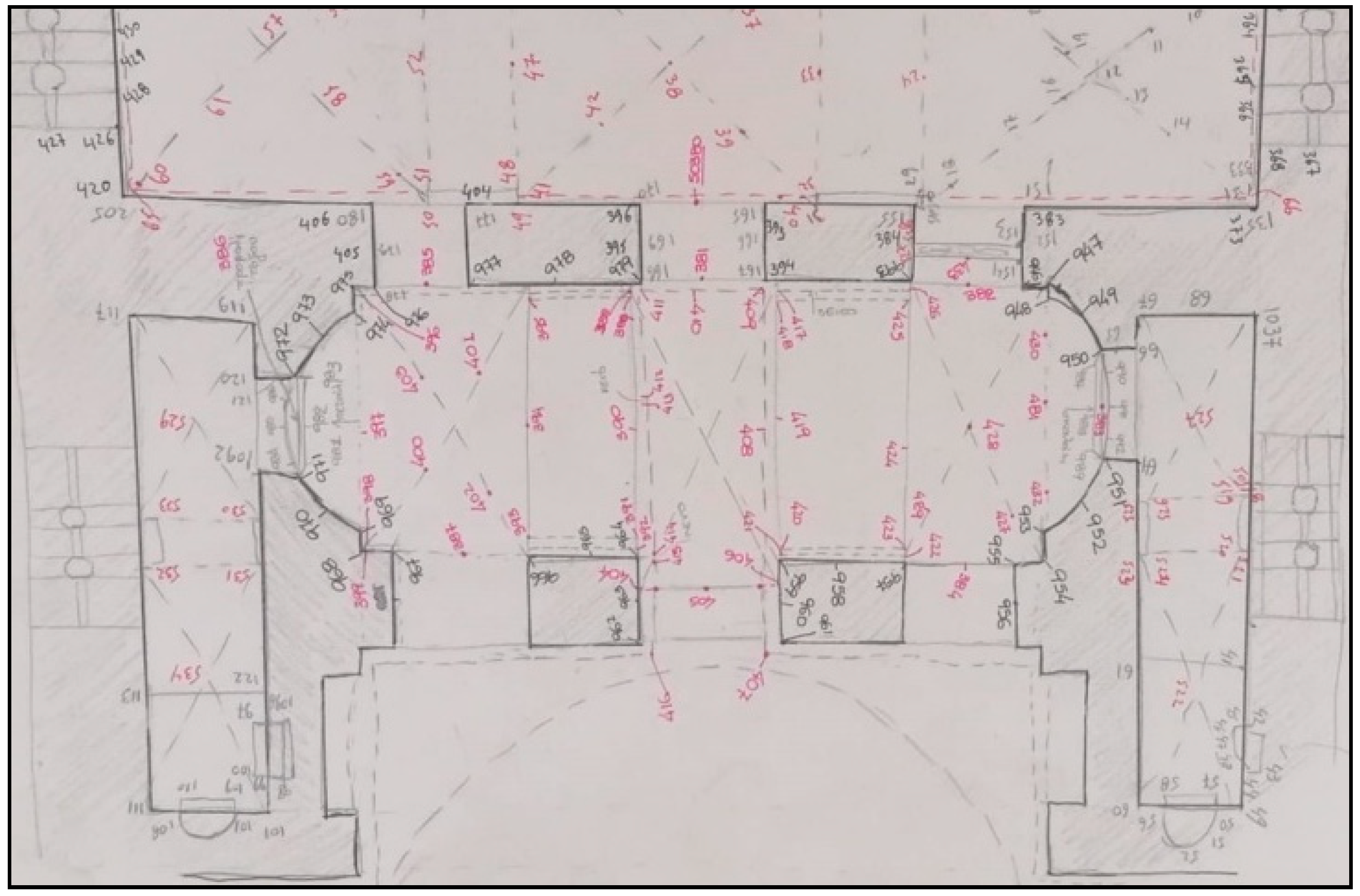
As already mentioned, back in 1999, more than 11,500 points were measured with a total station equipped with an add-on reflectorless EDM. These include tachymetric points and GCPs, both natural features and premarked with checkerboard targets. All these points had to be manually noted on properly improvised and detailed sketches (
Figure 16). Additionally, 994 B&W and 973 colored photos were taken from the same positions using analogue photogrammetric cameras. They were exact duplicates, from the same positions, and hence, only the colored ones were eventually processed for the final products. As the cameras were of large format (13 × 18 cm
2), the photos taken were fewer than would be required today with a smaller format camera. This in itself demanded meticulous planning and organization. Moreover, the planning for the placement of the checkerboard targets and the marking of the natural GCPs was also a time-demanding and challenging task. Moreover, a basket-carrying crane was used in order to take photos of the dome and the roof.
During the recent project, the GCPs were used only for the registration of the point clouds and for the checking of the internal geometry of the model. Not more than 80 points were measured. Thus, the sketches were much simpler and easier to draw. They had to contain only the positions of the GCPs and the approximate positions of the TLS setups.
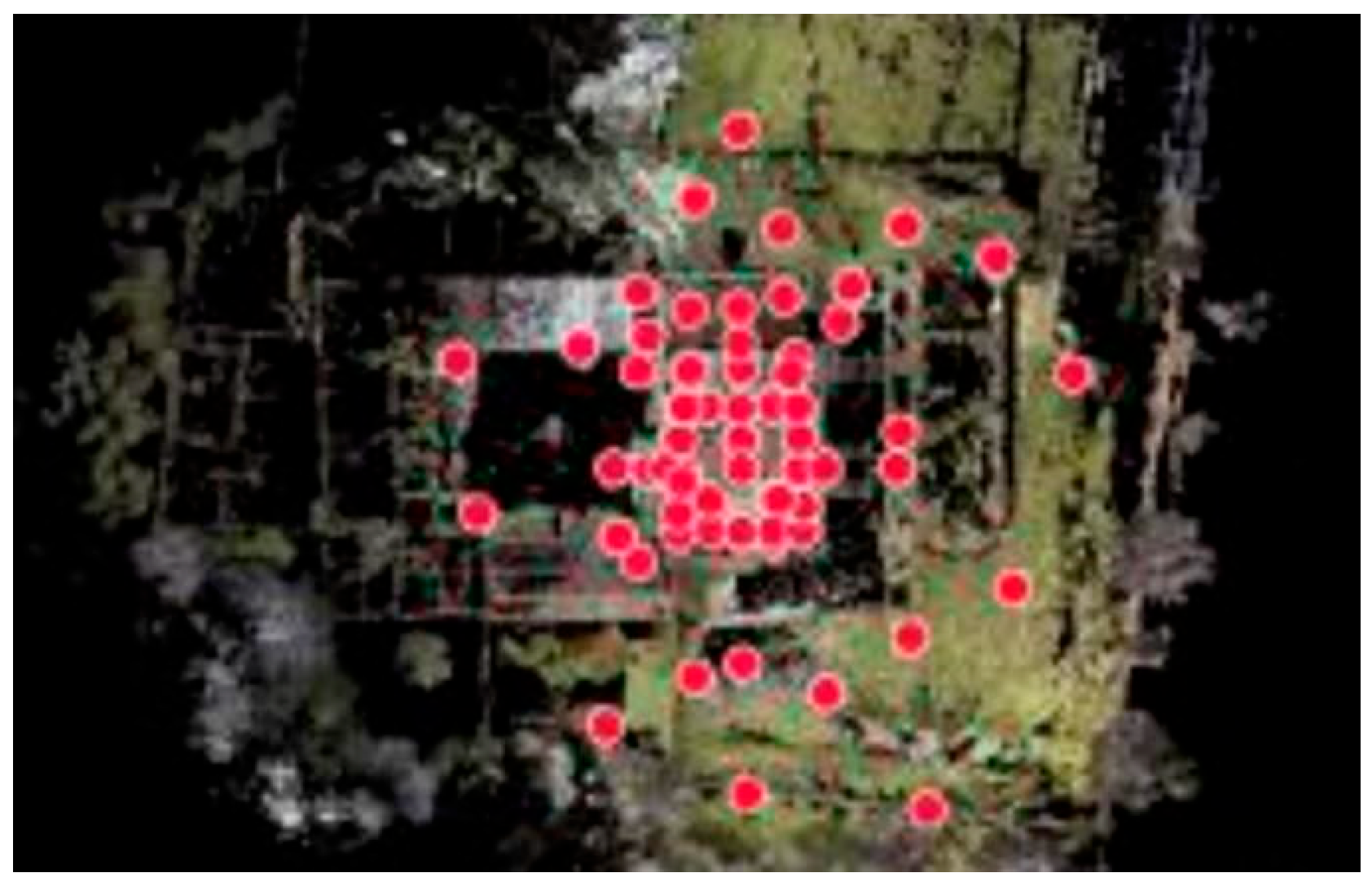
Each one of the 70 TLS setups (61 used—
Figure 17) required a pure time of 6 min (i.e., 7 h pure time or approx. 10 h mixed time). The UAV flight lasted no more than an hour. The images captured concerned the inaccessible parts of the Katholikon (i.e., the dome and the roof); no ground images were taken.
4.2. Processing and Drawings
Data processing for the 1999 project was as time-consuming and laborious as the field work. The classification and the archiving of the points measured and photographs taken were a rather complicated procedure. Most of the calculations were realized by non-commercial, especially in-house developed software, programmed in Q-Basic. In addition, the coordinates of the points that were on facades for projecting them in vertical sections had to be transformed to the corresponding plane for each section for the photogrammetric procedure to function in the digital photogrammetric workstation.
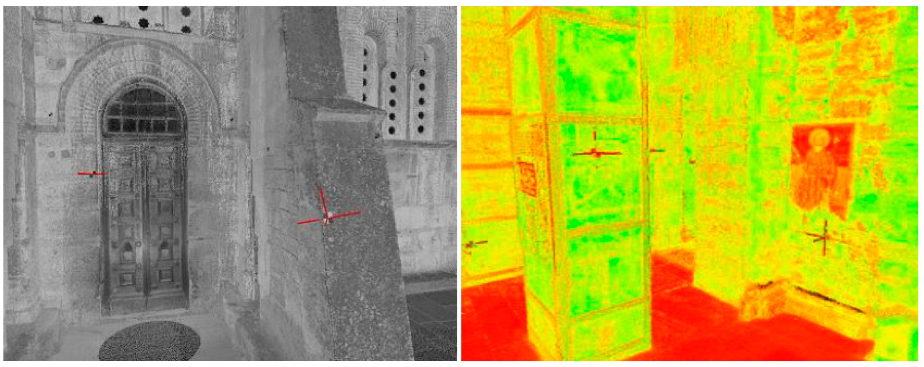
The evolution of technology brought innovations not only to geodetic equipment but also to the corresponding processing software. Consequently, the calculations of the coordinates of the geodetic network and the GCPs were performed with commercial software, with minimal manual interventions, concerning the quality of the solutions. The registration of the point clouds was performed in Cyclone Register 360 software. The procedure is semi-automatic as the user picks the GCPs (
Figure 18) or manually aligns the point clouds of the different setups.
Respectively, the same procedure was followed with the UAV photos, with the automated photogrammetric (SfM/MVS) software Agifost Metashape (v. 2.0.3). In order to define the different projection planes, the user can change the desired coordinate system (UCS) in the produced 3D model and create a section wherever they wish. Both procedures took place in a high-end PC, so the processing time for them was minimized.
4.3. Tracing the Changes
Based on the two series of drawings, before and after the restoration works, comparisons can be performed to monitor the alterations that occurred during the restoration project. Here, two major changes can be easily found.
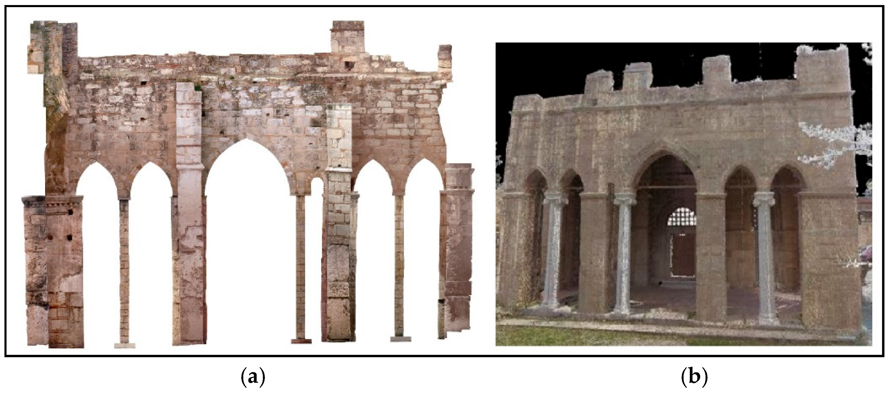
One concerns the west facade. There were three columns of orthogonal cross-section in 1999. Today, following the initial construction of the temple, these have been replaced by three different columns. The “new” Ionic style columns have a circular cross-section and are replicas of the initial columns of the temple (
Figure 19 and
Figure 20)
Another part that is restored is the part that leads to the roof of the church. In the 1999 diagram, the big masonry block over the door had collapsed. Nowadays, this has been replaced by a new one (
Figure 21).
4.4. Summarizing the Projects
Taking into consideration all the above factors and parameters, an estimation can be given of what would be the needs of the 1999 project (with the specifications of a corresponding restoration project), if that took place today with the equipment and software that was used in the 2023 project.
Table 1 summarizes the two projects’ frameworks and presents the aforementioned estimation.
It should be noted again that the 110 images taken with the UAV, during the recent project, concerned only the external inaccessible parts of the Katholikon. The documentation of the mosaics was not a part of the project, and the desired scale for the drawings was 1:50. Assuming the 1999 project occurred today, the use of a DSLR full-frame camera would have been inevitable. Concerning the images that we would need today, the number would probably be greater than the ~1000 that were taken back in 1999. This is because the cameras that were used back then were of a larger format than the DSLR cameras that are used today. In case SfM (Structure from Motion) and MVS (Multi-View Stereo) techniques were applied, the number of images would be even bigger.
In any case, there is no doubt that these 20 years of evolution have dramatically decreased the needs of the same project in terms of time and costs.
5. Discussion and Conclusions
The evolution of technology has given an abundance of equipment and methods to use for achieving the desired precision and minimizing the data acquisition time in situ. The key factor for the creation of a correct geometric diagram/plan is the combination of these methods, especially when it comes to areas of historical importance with increased detail on the surface and complex geometry. In order to carry out the documentation process in the most accurate and beneficial way, the appropriate combination of modern supplied methods and measuring instruments should be used.
This paper approached this evolution by comparing two geometric documentation projects concerning the Katholikon of the Holy Monastery of Daphni, separated by a time span of 24 years (1999–2023). Although they aimed at different results, both used the most modern equipment of their era.
The scope of the paper was to illustrate the changes in equipment and methods over the years. The data collection in the first project was performed with classical geodesy, i.e., reflectorless total station, and traditional photogrammetry with a metric camera and a large format hand-held camera, both analogue. The second project was carried out using a terrestrial laser scanner and images taken by a UAV.
This study highlights how technological evolution has transformed heritage documentation practices. The comparative approach demonstrates the substantial gains in efficiency, accuracy, and resource management. The findings underscore the value of modern tools like TLS and UAVs in capturing complex geometries with minimal invasiveness, and they provide a benchmark for future documentation projects.
The changes that are traced through these 24 years mainly concern the time needed, the equipment and the personnel to complete the project in order to deliver drawings and orthomosaics with the precision of 1:25 scale. The specifications of 1:25 scale are completely different from those of 1:50, not only in terms of accuracy, but mainly in terms of the detail of the drawings and information contained in them. Furthermore, it requires a different way of measuring and taking the images.
Moreover, a point cloud of the monument must have been among the deliverables.
In terms of data collection, tasks that needed several months to complete nowadays can be completed within a few days. The personnel who would work today on a project with the same specifications in terms of precision and deliverables could be no more than 5–6 people. With the proper use of the equipment, fieldwork has transformed into a much less tiring and arduous procedure.
In terms of data processing, again, there is an abundance of software that allows the production of 3D models and drawings, from which all the desired diagrams (e.g., floor plans, facades, cross-sections, etc.) can be extracted and digitized. Nevertheless, the digitization is a procedure that still needs plenty of time and special attention.
Furthermore, two areas were spotted where changes have occurred during these 24 years. The most interesting is in the west facade, where the three columns with rectangular cross-section were replaced with three circular cross-section Ionic-style columns.
Closing, it should be noted that, as in every other monument, also in the Holy Monastery of Daphni, geometric documentation was a major step in the process of restoring the basic stage for its rescue and its protection so that its history can be revealed and recognized by tourists or residents.
Future research should explore the integration of geometric documentation with advanced structural analysis tools, particularly for seismic vulnerability assessment. A multidisciplinary approach combining historical research, high-resolution surveys, and finite element modeling is essential for developing robust conservation strategies. Additionally, further work could assess the repeatability and long-term monitoring potential of such technologies for ongoing monument preservation.
