Article

Dynamic Object Mapping Generation Method of Digital Twin Construction Scene

1
School of Civil Engineering and Architecture, Xiamen University of Technology, Xiamen 360124, China
2
Fisheries College, Jimei University, Jimei District, Xiamen 361021, China
3
Xiamen Hymake Technology Co., Ltd., Xiamen 361008, China
*
Author to whom correspondence should be addressed.
These authors contributed equally to this work.
Buildings 2025, 15(16), 2942; https://doi.org/10.3390/buildings15162942
Submission received: 14 July 2025 / Revised: 9 August 2025 / Accepted: 16 August 2025 / Published: 19 August 2025
(This article belongs to the Section Construction Management, and Computers & Digitization)

Abstract

The construction environment is a highly dynamic and complex system, presenting challenges for accurately identifying and managing dynamic resources in digital twin-based scenes. This study aims to address the problem of object coordinate distortion caused by camera image deformation, which often reduces the fidelity of dynamic object mapping in digital construction monitoring. A novel dynamic object mapping generation method is proposed to enhance precision and synchronization of dynamic objects within a digital twin environment. The approach integrates internal and external camera parameters, including spatial position, field of view (FOV), and camera pose, into BIM using Dynamo, thereby creating a virtual camera aligned with the physical one. The YOLOv11 algorithm is employed to recognize dynamic objects in real-time camera footage, and corresponding object families are generated in the BIM model. Using perspective projection combined with a linear regression model, the system computes and updates accurate coordinate positions of the dynamic objects, which are then fed back into the camera view to achieve real-time mapping. Experimental validation demonstrates that the proposed method significantly reduces mapping errors induced by lens distortion and provides accurate spatial data, supporting improved dynamic resource perception and intelligent management in digital twin construction environments.

1. Introduction

The construction site is a dynamic and complex environment characterized by constant changes in spatial configurations, temporal sequences, and resource allocations. Managing such environments involves tracking a wide array of dynamic objects including construction materials, machinery, and personnel, which have a critical impact on construction safety, efficiency, and quality [1]. In recent years, the integration of information and communication technologies (ICT) into the architecture, engineering, and construction (AEC) industry has advanced significantly, enabling the digitalization of the entire project lifecycle [2]. Among these technologies, Building Information Modeling (BIM) has emerged as a central platform for data integration and collaborative planning across disciplines [3].
To extend BIM capabilities beyond static modeling, Digital Twin (DT) technology has been introduced to create real-time, synchronized virtual representations of physical assets and processes [4,5]. A digital twin operates by capturing real-world data—via sensors, cameras, and IoT devices—and reflecting these changes in a virtual model, enabling bidirectional interaction between the physical and digital domains [6]. This concept has shown promising results in facility management and manufacturing; however, its application in the construction phase remains underdeveloped due to the inherent variability and unpredictability of construction environments [7,8].
Digital Twin (DT) technologies hold significant promise in the construction industry by enabling proactive safety monitoring, real-time decision making, and process optimization [9]. Frameworks such as Digital Twins for Construction Safety (DTCS) have begun to leverage 4D BIM and semantic safety ontologies to predict potential hazards and support risk mitigation strategies [10,11,12]. These initiatives illustrate the transformative potential of DT in improving construction site safety, productivity, and resilience.
However, despite this promise, substantial gaps remain between DT theory and practical deployment, particularly in the dynamic and unpredictable context of active construction sites. Most existing implementations still rely on static models or single-sensor inputs, failing to provide real-time, spatially accurate representations of moving objects such as workers or machinery. Inaccurate localization—exacerbated by visual distortions from wide-angle lenses or suboptimal camera configurations—undermines the reliability of digital–physical synchronization, limiting the effectiveness of DT-enabled safety and management systems [13,14,15].
This gap is particularly critical in construction, where timely and accurate awareness of dynamic object locations can directly impact worker safety, site coordination, and operational efficiency. Bridging this divide requires robust methods that can integrate real-world sensor data with BIM in a spatially coherent and temporally responsive manner.
To address this challenge, this study proposes a computational method for dynamic object mapping in DT-enabled construction environments. By integrating camera intrinsic/extrinsic parameters and establishing a synchronized virtual camera within the BIM environment, the proposed method enables accurate projection of detected objects into the digital twin. Leveraging YOLOv11 for real-time detection and applying a linear regression model for distortion correction, the system enhances the fidelity and responsiveness of DT object representations, thereby supporting more intelligent and adaptive construction management.
To address these limitations, this study proposes a computational method for generating dynamic object mappings in digital twin-based construction scenes. By integrating physical camera parameters—such as intrinsic/extrinsic geometry, field of view (FOV), and pose—into the BIM environment using Dynamo, a virtual camera synchronized with the physical environment is established. The YOLOv11 object detection algorithm is then used to identify dynamic objects in real-time camera footage, and a linear regression model corrects distortion errors to ensure accurate coordinate mapping. This approach not only enhances the spatial fidelity of dynamic object representation but also supports timely decision making in construction management. Experimental validation demonstrates the method’s potential to improve the precision, responsiveness, and practical applicability of digital twins in intelligent construction workflows.

2. Literature Review

2.1. Composition of Digital Twin Construction Scene

In the field of construction management, the static information provided by Building Information Modeling (BIM) serves as the core foundation for the application of digital twin technology [6,7]. Within the framework of construction safety digital twins, Speiser and Teizer [16,17] integrated multiple data sources [18] to develop a Virtual Training Environment (VTE) that combines BIM, construction schedules, and safety regulations, offering personalized feedback to project managers [19,20]. However, due to the dynamic and unstructured nature of construction sites, current approaches often require significant human and material resources, leading to inefficiencies and a higher likelihood of human error [21,22].
To address these challenges, Shariatfar et al. [23] integrated deep learning techniques with BIM to develop a real-time digital twin-based safety monitoring system capable of providing proactive safety analytics and predictions. Similarly, Wang et al. [24] proposed a digital twin-enabled 3D modeling framework that utilizes BIM to simulate construction processes and establish bidirectional mappings between workers’ physical postures and their corresponding virtual models [25]. As the application of 4D-BIM continues to advance, it becomes evident that certain workspaces on site remain “non-modeled” within the BIM environment. These spaces are characterized by irregular shapes, undefined orientations, and non-fixed positions [26]. In response, Guo [27] developed a three-phase analytical model for non-modeled workspaces, offering a practical methodology for their management based on 4D-BIM.
Data acquisition is fundamental to enabling digital twin construction applications [28,29]. Lu et al. [30,31] proposed a digital twin system architecture that leverages a semi-automated data acquisition approach, integrating imaging technologies with computer-aided processing, to construct accurate and accessible building level digital twins. Mokhtari et al. [32] further enhanced the digital twin framework by integrating construction documents and management records, while also incorporating real-time system-generated data. Virtual simulation, a commonly adopted representation in digital twin applications [33,34], allows for modeling of behavioral, performance, and response characteristics under varying conditions through algorithmic integration with the digital models [35,36,37].

2.2. Calculation Method of Scene Object Conversion

Surveillance cameras are commonly used as essential auxiliary tools on construction sites [38]. They provide real-time video streams of the site [23], assist in monitoring unauthorized activities [39], and support the identification of potential hazards [40]. With the advancement of deep learning techniques, the integration of intelligent video analytics into construction environments has become increasingly feasible and impactful. One critical factor that influences the effectiveness of surveillance systems is the maximum coverage range of the camera [41], which is directly related to its Field of View (FOV) [42]. A larger FOV corresponds to a wider visual coverage area [43], making it a key parameter in the planning and optimization of camera deployments. As such, many studies have incorporated FOV modeling into camera coverage analyses [44,45]. For example, Chen et al. [46] and Zhu et al. [47] employed two-dimensional circular FOV model to assess visibility and eliminate overlapping zones between multiple cameras. Zhou et al. [48] proposed a method for integrating BIM models with live camera feeds, resolving inconsistencies in scale, coordinate systems, and object representations between the BIM environment and video imagery.
The principle of perspective projection is a geometric technique used to project three-dimensional objects in physical space onto a two-dimensional image plane through a camera [49]. The core of this method lies in using intrinsic and extrinsic camera parameters to convert pixel coordinates in the image into real-world 3D coordinates [50,51]. By matching 2D image points with their corresponding 3D counterparts in the construction environment [52,53,54], mapping functions are used to transform image data from two-dimensional space into spatially accurate three-dimensional coordinates [55]. For instance, Son et al. [56] implemented this principle to enable pixel-to-coordinate conversion in a real-world context. Wu and Hou [57] applied perspective mapping to transform human target positions captured in images into coordinate data, enabling real-time tracking and hazard recognition.

2.3. The Shortcomings of Existing Research

Although digital twin technology has received widespread attention in the field of construction in recent years and related research has achieved certain results, there are still key shortcomings and research gaps that limit its in-depth application in construction scenarios.
(1) The accuracy of dynamic object mapping is limited, and there is a lack of high-precision fusion mechanism with BIM models. At present, most research focuses on BIM modeling and visualization of static building objects, while the recognition and spatial positioning of dynamic objects (such as construction personnel, material transportation, etc.) are still in their early stages. Especially in terms of geometric projection and coordinate mapping between unstructured image data and BIM models, there is still a lack of unified and accurate fusion mechanisms.
(2) The target detection model has poor adaptability to complex construction scenarios and insufficient robustness. The construction site environment is complex, with interference factors such as obstruction, changes in lighting, and structural obstruction. However, most of the object detection models used in existing studies (such as YOLO series, Faster R-CNN, etc.) are trained on universal datasets, which often exhibit problems such as unstable detection, high false alarm rate, and missed edge targets in specific building scenes, affecting the accuracy of subsequent coordinate extraction and scene reconstruction.
(3) There is a lack of a positioning and correction mechanism that takes into account image distortion and viewing angle deviation. Most studies assume that the images captured by the camera have an ideal linear projection relationship, ignoring the impact of image distortion effects such as perspective compression on the accuracy of object coordinate back projection. At the same time, there is no rigorous mapping model established between the camera and the BIM virtual perspective, resulting in systematic errors between virtual and real coordinates, which affects the synchronization accuracy of dynamic objects in DT scenes.
Therefore, the current research has not fully addressed the core issue of “how to achieve high-precision and dynamic mapping between multi-source perception data and BIM models”, especially under conditions of image distortion and perspective deviation. The lack of integrated methods for object detection and spatial mapping in construction scenarios hinders the real-time performance, robustness, and application promotion of digital twin systems during the construction phase.

3. Research Objectives and Problem Definition

3.1. Research Questions and Objectives

Although existing research has extensively explored the potential of digital twin technology in construction, there are still significant shortcomings in real-time mapping of dynamic objects during the construction phase. Especially in the camera environment, due to issues such as lens distortion and spatial geometric mismatch, there may be deviations in the matching of objects between the image and the BIM coordinate system, which in turn affects the accuracy and practicality of digital twin scenes. Therefore, this study focuses on the following core research questions:
(1) How to achieve accurate recognition and coordinate mapping of dynamic objects in construction scenes when there is distortion in the camera?
(2) How to accurately match the detected two-dimensional image coordinates with the BIM three-dimensional coordinate system and construct a real-time updated digital twin mapping mechanism?
To solve the above problems, this paper proposes a calculation method that integrates YOLOv11 object detection and BIM perspective mapping, and achieves accurate mapping of dynamic targets in digital twin construction scenes by correcting perspective projection errors and lens distortions. The research objectives include:
(1) Build a virtual mapping environment that considers the participation of FOV parameters inside and outside the camera;
(2) Using deep learning algorithms to identify and extract key object image information;
(3) Realize automatic conversion and update of object image coordinates to BIM coordinates;
(4) Verify the mapping accuracy and system performance of the proposed method in practical scenarios.

3.2. Digital Twin Construction Scene Integration Framework

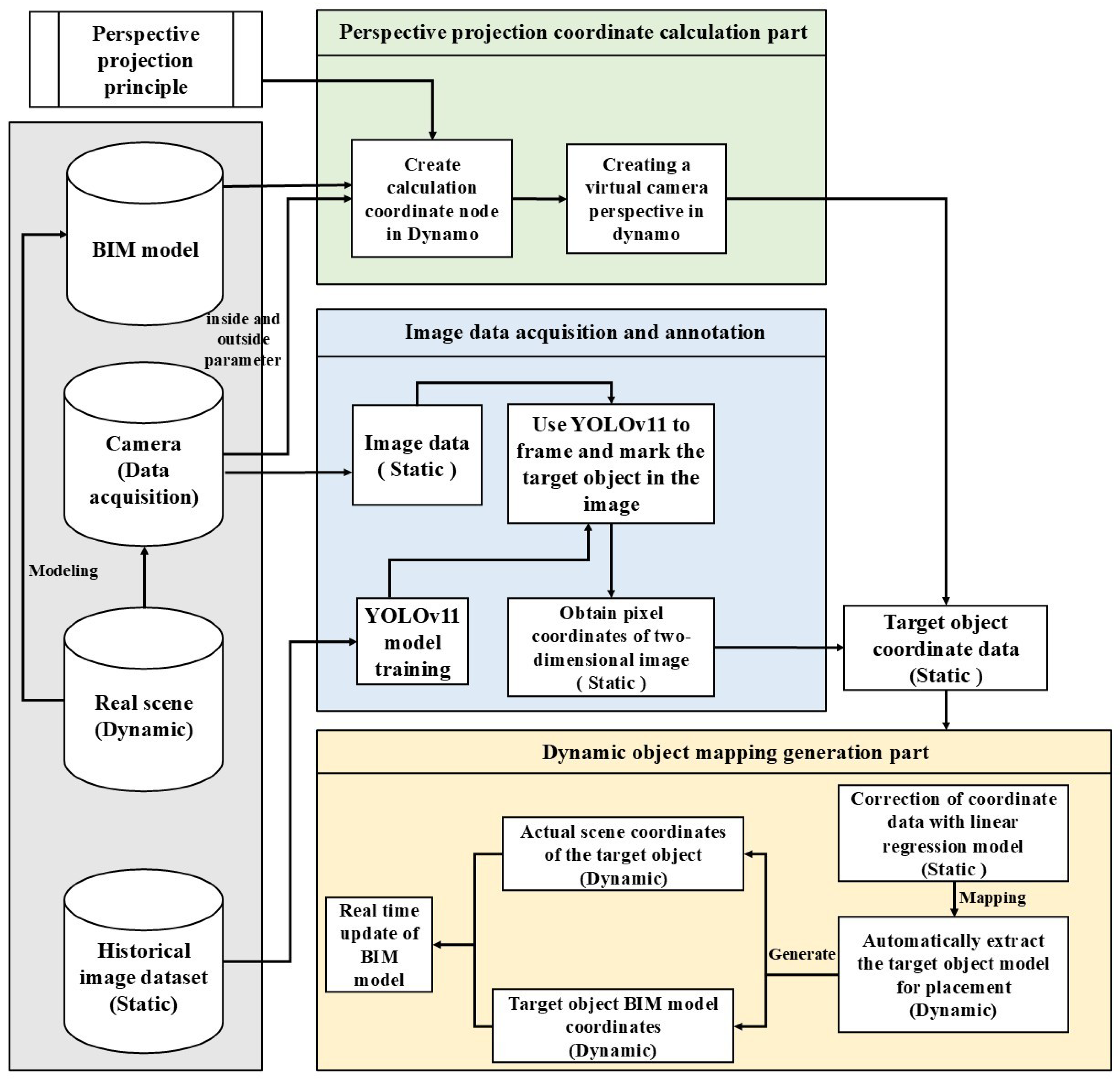
The method principle proposed by the institute is shown in Figure 1. The core of this is to input the image of the target object captured by the actual camera into the target detection algorithm YOLOv11 model, and perform frame selection and classification on the target object to obtain a rectangular frame of the target object. Then, by creating a virtual camera perspective in Dynamo, the actual scene is fully mapped to the BIM model, and the virtual camera is matched with the position, FOV, and direction of the camera in the actual scene. Finally, the midpoint of the bottom edge of the rectangular box is selected as the reference point, and the coordinate data of the reference point in the BIM model is obtained through the FOV and perspective projection calculation of the virtual camera in the model, thus realizing the real-time mapping and generation of dynamic objects in the digital twin scene. The coordinates of the target object are automatically calculated in the BIM model through the Dynamo plug-in, effectively avoiding the calculation errors caused by the perspective projection algorithm and reducing the impact of camera lens distortion. The actual coordinate information of the YOLO algorithm is provided, which further improves the accuracy of object mapping and generation in the digital twin scene.
The method proposed by the research institute can significantly improve the recognition accuracy and real-time coordinate matching ability of digital twins on dynamic objects in construction sites, providing a scalable technical path for safety management, intelligent monitoring, and automated construction on construction sites, and laying the technical foundation for the realization of a truly dynamic digital twin platform in the future.

4. Materials and Methods

The research framework is shown in Figure 2. It is mainly divided into three parts: (1) image data acquisition and annotation; (2) calculation of perspective projection coordinates; (3) dynamic object mapping generation.

4.1. Image Data Acquisition and Annotation

The study uses the YOLOv11 object detection algorithm for object recognition and frame selection of image data. The YOLOv11 model was first released at the YOLO Vision 2024 (YV24) conference in 2024, representing another major technological breakthrough in the field of real-time object detection. This model integrates a new generation feature extraction module with a lightweight convolution architecture, significantly improving the perception ability of fine-grained features while maintaining a reduced number of model parameters. Therefore, YOLOv11 exhibits a faster detection speed and higher positioning accuracy in complex dynamic environments, making it suitable for high real-time scenarios such as construction monitoring.
The YOLOv11 model achieves efficient object recognition through an end-to-end structure. It directly extracts convolutional features after image input and outputs detection results containing target category and location information, without the need for traditional candidate region generation processes, thereby significantly improving detection efficiency and feature expression ability.
Therefore, the study uses cameras to capture real-time images of construction sites, including dynamic objects such as construction tools, equipment, and materials. The collected image data are input into the YOLOv11 model for object detection analysis. The model performs bounding box localization and category annotation on each target object present in the image, achieving automatic recognition and structured annotation of target objects in the scene.
Train the YOLOv11 model from scratch to adapt to specific building scene object detection requirements. The pre-training weights of the model are derived from the COCO dataset, which contains over 118,000 annotated images covering 80 common objects. Then, the model was trained using a self-built construction site image dataset, which contains approximately 10,000 images covering key object categories such as workers, mechanical equipment, and safety helmets. All images are equipped with bounding boxes and category labels, and are divided into training, validation, and testing sets in an 8:1:1 ratio. The mAP value of the validation set is 86.2%, indicating that the model has good accuracy and robustness in identifying key dynamic objects in construction scenes.

4.2. Calculation of Perspective Projection Coordinates

4.2.1. Definition of Camera Parameters

The angle formed by the two edges of the maximum range of the lens through which the object image of the measured object can pass with the lens as the vertex is called the field angle [58]. If the object exceeds the range of the field angle, it will not be captured [59]. The field angle also includes the horizontal field angle (HFOV, β), the vertical field angle (VFOV, α), and the diagonal field angle (DFOV, ω). Since the photosensitive surface of the camera optical equipment is rectangular [60], the field angle can be calculated from the image object diameter of the diagonal of the rectangular photosensitive surface, as shown in Figure 3.
The field angle of view of the camera is fixed and known, and the range that can be captured is also related to the focal length of the lens. Therefore, the object distance s that can be captured by the camera can be calculated by Formula (1).
tan ω / 2 = a c / s    
where ω is the diagonal field angle; ac is the visual range radius of the camera; s is the object distance that the camera can capture

4.2.2. Shift of Perspectives

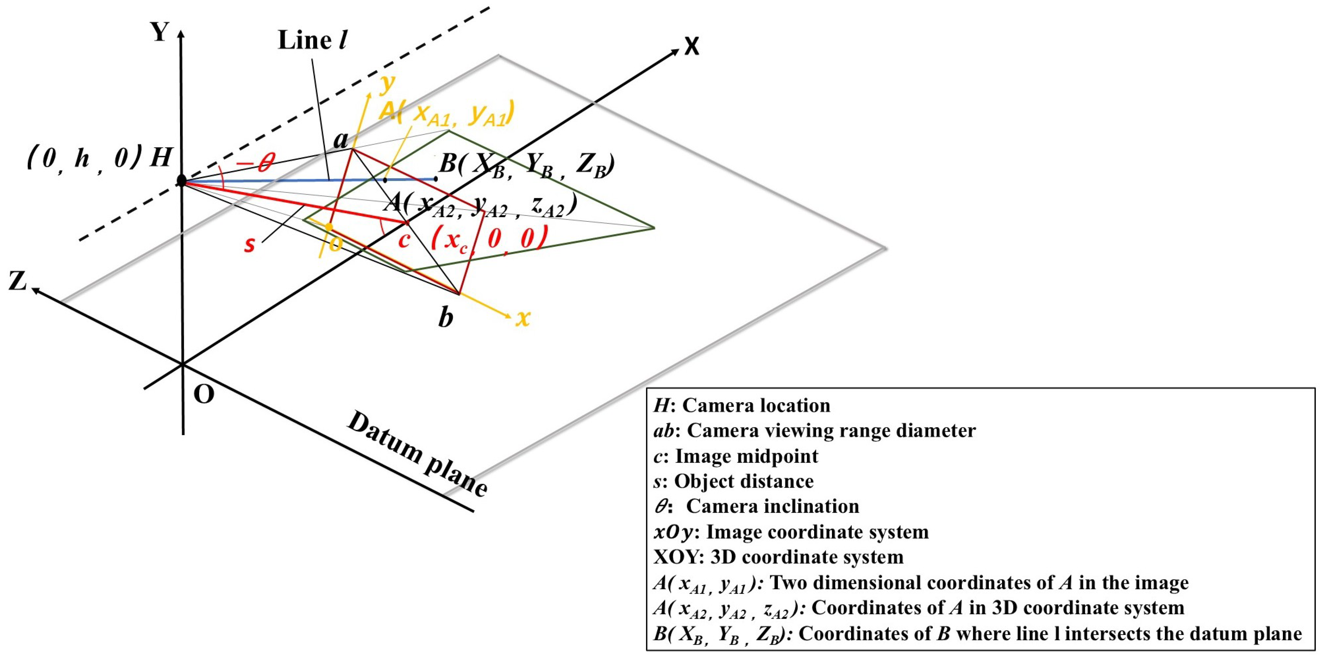
Camera imaging involves the conversion between the world coordinate system, camera coordinate system, and image coordinate system. According to the perspective projection principle, the two-dimensional image captured by the camera is the projection of three-dimensional space on the plane. Therefore, based on the camera posture and the target coordinates in the image, the position of the target object in the real world can be determined. Based on the method proposed by Son et al. [56], a model of perspective projection principle is built, which converts the pixel coordinates of two-dimensional images into three-dimensional camera coordinates, and then converts them into world coordinates through the transformation matrix. The model is shown in Figure 4.
The camera is located at point H, and its elevation angle with the horizontal direction is θ. The reference plane is the plane where the target object is located, and is set on the same plane as the center of the target object, that is, the plane composed of X axis and Z axis. Straight line s is the object distance (optical axis) that can be captured by the camera, and point c is the intersection of the optical axis and the reference plane. According to the calculation result of Formula (1), the coordinate of point c and the trigonometric function relationship of angle θ can be calculated, as shown in Formulas (2) and (3).
x c = s 2 h 2          
sin θ = h / s    
where s is the object distance that can be captured by the camera; h is the erection height of the camera; ac is the visual range radius of the camera.
According to the perspective projection principle, the image captured by the camera is perpendicular to the optical axis, and the projection on the reference plane is trapezoid. In order to simplify the calculation, the midpoint of the image is set as point c. For any two-dimensional coordinate point A in the image, its coordinates in the three-dimensional coordinate system can be calculated according to Formula (4), where the two-dimensional coordinate point A(xA1, yA1) is the pixel coordinates.
x A 2 = x c y A 1 · sin θ y A 2 = y A 1 · cos θ z A 2 = x A 1
Then the equation of line l passing through points A and H is obtained according to Formula (5).
x / x A 2 = ( y h ) / ( y A 2 h ) = z / z A 2
Bring the point B where the line l intersects the datum plane into Formula (5) to calculate the three-dimensional coordinates of point B, as shown in Formula (6).
x B = [ h / ( h y A 2 ) ] · x A 2 y B = 0 z B = [ h / ( h y A 2 ) ] · z A 2
Finally, the coordinate system can be integrated into the world coordinate system by multiplying the transformation matrix M. The transformation matrix M of the camera is the combination of the camera internal parameter matrix K and the external parameter matrix, as shown in Formula (7).
M = K [ R T ]
The form of camera intrinsic parameter matrix K is usually shown in Formula (8).
k = f x 0 c x 0 f y c y 0 0 1
where fx and fy are the focal lengths of the camera in the direction of x and y, in pixels; cx and cy are the coordinates of the main point of the image (the pixel coordinates of the image center).
The external parameter matrix describes the position and direction of the camera. According to Figure 4, the coordinate system selected by the research model is aligned with the origin of the world coordinate system and has no rotation, that is, R is the identity matrix and T is the translation vector. At this time, the transformation matrix M is the internal parameter matrix K.

4.2.3. Correction Through Linear Regression

Because the distortion of the camera will bring geometric deviation, the coordinate data of the target object generated by the model will have linear systematic error. According to the perspective projection model constructed in the study, the Y-axis coordinate value of point B is 0 (as shown in Formula (6)), the independent variable of error is only the coordinate data of X-axis and Z-axis, and the dependent variable is the deviation value of X-axis and Z-axis coordinate data. According to the image collected by the camera and the distortion error generated by the system environment, the linear regression (LR) method is used to predict and correct the deviation. Linear regression is used to fit the linear relationship between independent variables and dependent variables for prediction [61], and the least square method is used to provide a linear equation. Then, convert it into Python code (Use Python version 3.13 and write and run it in PyCharm software.) and run it in the corresponding software. The principle of the model is shown in Figure 5.
First, calculate the deviation of each point as shown in Formula (9), and then establish the linear regression model as shown in Formula (10) for the X-axis and Z-axis directions.
x i = x B i x i z i = z B i z i
x i = a · x i + b z i = c · z i + d
where a, b, c, and d are regression coefficients; xBi, zBi are the point coordinates of each target object obtained through calculation; xi, zi are the actual coordinates of the target object (which can be obtained through the BIM model); i is the number of target object points in the scene (i = 1, 2, …, n).
The regression coefficient is obtained by fitting the objective function of the least square method. By constructing the minimum sum of squares of residuals as shown in Formula (11), and then calculating the partial derivatives of a, b, c, and d and making them zero, the closed form solution shown in Formula (11) can be derived, so as to obtain the value of the regression coefficient.
min a , b i = 1 n x i a x B i + b 2 min c , d i = 1 n z i c z B i + d 2
where xBi, zBi are the point coordinates of each target object through calculation; i is the number of target object points in the scene (i = 1, 2,…, n).
a = x B i x B ¯ x i x ¯ / x B i x ¯ B 2 b = x ¯ a x ¯ c = z B i z ¯ B z i z ¯ / z B i z B ¯ 2 d = z ¯ c z ¯
where a, b, c, and d are regression coefficients; xBi, zBi are the point coordinates of each target calculated by the model; x ¯ B, z ¯ B, Δ x ¯ , Δ z ¯ are the average values; i is the number of target object points in the scene (i = 1, 2,…, n).
Finally, the corrected coordinate data are calculated by Formula (13).
x B i = x B i x i z B i = z B i z i
where xBi, zBi is the corrected coordinate; xBi, zBi are the point coordinates of each target calculated by the model; Δxi, Δzi are the deviations predicted by the linear regression model.

4.3. Dynamic Object Mapping Generation

4.3.1. Virtual Camera Angle Setting

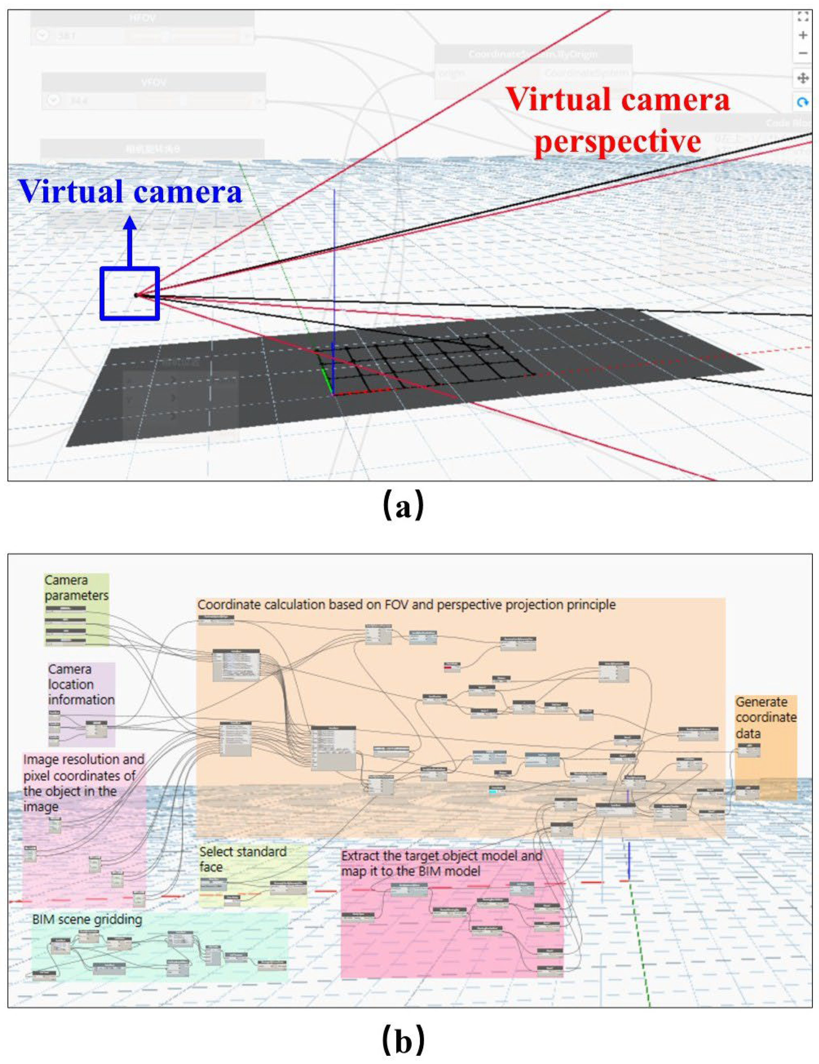
Visual Programming Language (VPL) tools based on BIM have been widely used in the extension research of Building Information Modeling in recent years, especially in achieving dynamic scene perception and visual interaction, showing great potential [60,62]. To achieve high-precision mapping between construction sites and digital models, this study constructed a virtual camera system as shown in Figure 6a on the Dynamo platform to simulate the imaging mechanism of cameras in real construction scenes. Utilizing its graphical programming advantages, it integrates multiple input modules including camera parameters, image coordinates, and BIM grid data, effectively reducing the impact of image distortion and calculation errors on the accuracy of 3D coordinate restoration.
As shown in Figure 6b, the internal and external parameters of the actual camera, including focal length, principal point position, spatial pose, and other key imaging elements, are imported through input layers (camera parameters, camera location information, image resolution and pixel coordination of the object in the image, BIM scene gridding) in the Dynamo environment. At the same time, the key pixels extracted by the YOLOv11 object detection algorithm in the input image are used as geometric constraints and fused with the field of view and perspective projection geometric model of the virtual camera. On this basis, the constructed virtual camera maintains consistency with the physical camera in terms of position, posture, and viewing angle range, thereby achieving physical consistency mapping of the virtual viewing angle in the BIM model, as shown in Figure 6a. Grid partitioning in BIM scenarios provides a structured foundation for coordinate projection, ensuring traceability and measurability of projection relationships.

4.3.2. Mapping Generation

After setting up the virtual camera, the system enters the processing flow of the computing layer and output layer. By using Select standard face and Coordinate calculation based on FOV and perspective projection principal nodes, the actual spatial position of the target object in the BIM coordinate system is calculated based on pixel points. Specifically, the study selected the standard plane on which the object is attached as the reference plane, and used the camera cone and perspective projection formula for spatial back projection to obtain the three-dimensional spatial coordinates of key feature points such as point A.
Furthermore, by utilizing the key point features and geometric shapes of the target object, the system can automatically match and extract the corresponding target BIM component model (Extract the target object model and map it to the BIM model). At the same time, based on the voxel method and centroid estimation algorithm, the position of the target object is high-precision corrected, and finally generates the spatial coordinate information of the target (Generate coordinate data). As shown in Figure 6b, the successful mapping of the pixel coordinates of point A in the image and the generation of its three-dimensional coordinate position in the BIM model signify the achievement of a coordinate closed-loop between virtual and real scenes.
In terms of real-time performance, the image processing module is based on the YOLOv11 model, with an average frame rate of 21.3 FPS, which means it can process about 21 frames of images per second. The average delay in the coordinate mapping and data output stage is 84 ms, which can meet the “quasi real-time” monitoring requirements in most construction scenarios (total system response time < 0.2 s). And it has good scalability and parallel processing capabilities, supporting simultaneous recognition and coordinate updates of multiple targets, providing an effective technical path for dynamic object recognition and monitoring in digital twin environments [63,64].

5. System Test and Results Analysis

5.1. System Test

5.1.1. Scene Construction and Image Data Acquisition

The study selected indoor testing for the system, as shown in Figure 7. For the convenience of calibrating the position of the camera and target object, a scene marking grid is used to calibrate a total of 28 points (Mark with numbers in Figure 7) in the actual scene, where each grid is divided according to the floor reference grid, and the size of each grid is 60 cm × 60 cm.
In the experiment, the camera commonly used in the actual scene with a focal length of 6mm is selected as the equipment channel for obtaining the on-site image data. The specific parameters of the camera are shown in Table 1. The external fixation parameters of the camera are: height h = 187cm, external angle θ = −22°.

5.1.2. Frame Selection and Classification of Image Data

The adopted YOLOv11 model uses the stochastic gradient descent (SGD) optimizer for 100 iterations of training, with a learning rate of 0.01 and a weight attenuation of 0.001. The batch size is set to 8, and the size of the input image is 1920 × 1080 pixels. The obtained image data are processed through the YOLOv11 model to obtain the framed and classified target objects.

5.1.3. Distortion Error of Target Object and Real-Time Mapping Generation

Camera distortion is actually the general term of the inherent perspective distortion of optical lens, which will lead to the phenomenon of geometric deviation between the imaging image and the actual scene, and the image has certain distortion. In order to effectively reduce these errors, a coordinate mapping system of virtual and real space is constructed to improve the accuracy of dynamic scene management and realize the real-time mapping and generation of dynamic objects.
First, in the BIM model, build a three-dimensional coordinate system consistent with the physical coordinate system of the actual scene. At the same time, according to the field of view angle and perspective projection formula, a virtual camera perspective is created in Dynamo, which completely maps the actual scene to the BIM model, and the position, field of view angle, and direction of the virtual camera are the same as those of the camera in the actual scene.
Then, the midpoint of the bottom edge of the boundary box of the target object is selected as point A, and the two-dimensional image pixel coordinates of point A are obtained through the YOLOv11 model. Import the pixel coordinate data into the perspective of the virtual camera to calculate the coordinate position data of point A in the BIM scene, so as to dynamically generate and update the target position in the BIM, ensure the accurate alignment of the target position in the scene, and make up for the disadvantage that the YOLO model can only automatically provide the target pixel coordinates. The process and results are shown in Figure 8.

5.2. Analysis of Test Results

5.2.1. Target Object Detection and Classification Performance

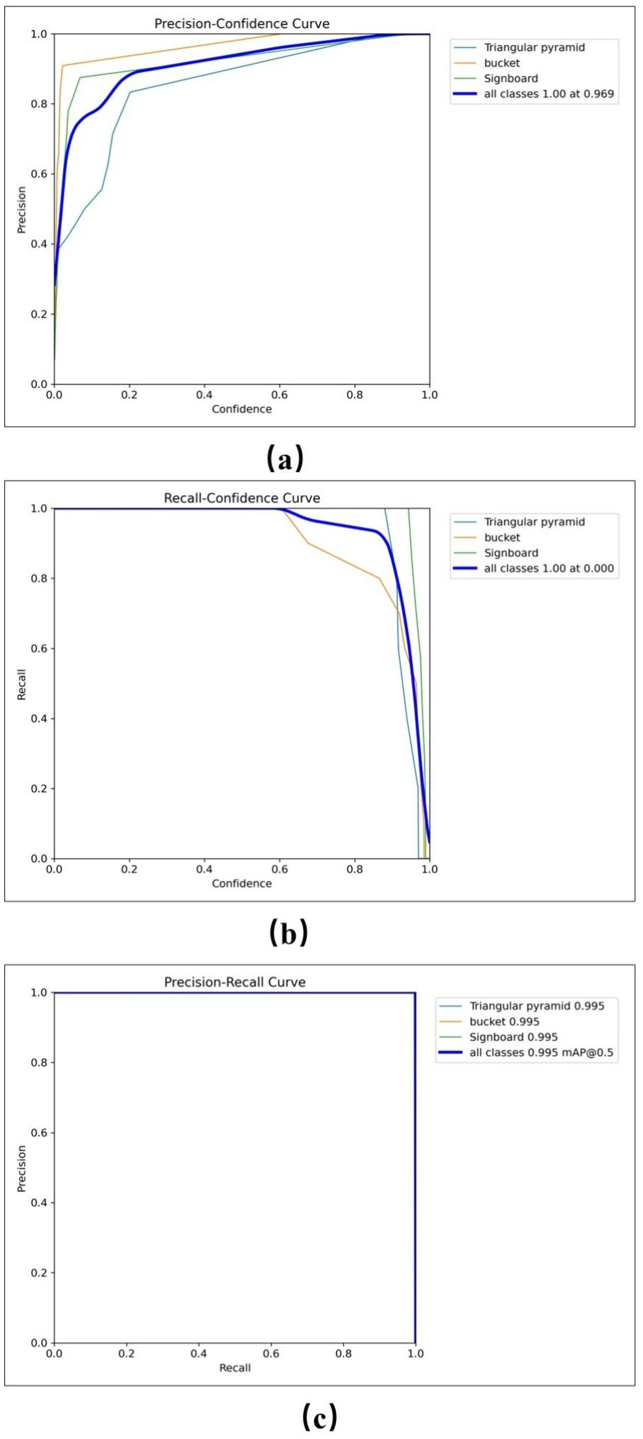
The research selected the PR curve (Precision–Recall Curve) to measure the detection performance of the model, and analyzed the precision and recall under different thresholds, as shown in Figure 9.
Accuracy refers to the percentage of detected objects accurately identified, while recall rate refers to the percentage of real objects successfully detected. According to the calculated accuracy and recall rate, the AP of each category can be calculated as the area under the accuracy recall rate curve, as shown in Formulas (14)–(16). The closer the curve is to (1, 1), the better the performance of the model; if the curve is low, there are more false positives (FPs) or false negatives (FNs).
P = T P / ( T P + F P )
R = T P / ( T P + F N )
A P = 0 1 P ( R ) d R
where TP stands for true positive or correct classification, FP stands for false positive or false classification, and FN stands for false negative or false classification into different categories.
It can be seen from Figure 9c that the YOLOv11 model selected in this experiment has better performance, with less false positive (FP) or false negative (FN), and the map value of this model is as high as 99.5% (IOU ≥ 50%).

5.2.2. Coordinate Accuracy of Target Object

In order to evaluate the accuracy of the proposed method, the points in the scene are divided into three parts according to the viewfinder range and visual distance of the camera. Then the actual coordinates of the target object at each node are compared with the model coordinate data calculated by Dynamo, and corrected by the established linear regression model.
First, compare the data generated by the operation with the actual point data, and the results are shown in Figure 10a. And from the data of the test points, it can be seen that the Δx value of each point decreases linearly with the decrease in the actual X-axis coordinates, and the Δz value is positively correlated with the actual Z-axis coordinates, which conforms to the linear characteristics.
Then, according to Formulas (9)–(13), calculate the point data corrected by the linear regression model, and compare it with the actual data. The results are shown in Figure 10b, where the regression coefficient is a = −0.08, b = 0.65, c = 0.12, d = 0.02.
As can be seen from Figure 10a, there is a systematic deviation in the X direction, which is generally offset to the right. The position of the target in the BIM is greater than the position of the actual point ID (the Red Cross is on the right side of the blue point), and the deviation amplitude decreases with the decrease in the X actual coordinate. For example, the deviation of point 1, point 8, point 15, and point 22 is greater than 0.55 m, while the deviation of point 7, point 14, point 21, and point 28 is less than 0.05 m. However, there is a nonlinear deviation in the Z direction, the deviation in the positive Z direction is small (about 0.07 m), and the deviation in the negative Z direction increases significantly (up to 0.26 m). The error vector in the Z direction is longer in the negative Z region, such as point 28, and the deviation in the edge point, such as the deviation from point 22 to point 28, is less than 0.05m. The direction deviation is obviously larger than that of the central region.
It can be seen from Figure 10b that the data deviation after correction is significantly reduced. Although there are still some errors at the edge points, the maximum is not more than 0.1m, such as point 1, point 8, point 15, point 22, and point 24–28. At the same time, the offset direction of each point is different from the overall upward left direction in Figure 10a, and the offset direction is divergent, but they are all within the radius of 0.05 m circle centered on the point.
The summary of the average error of the coordinate accuracy of the target object in the far, middle, and near parts is shown in Table 2. Overall, the standard deviation of error in the X-axis direction is much larger than that in the Z-axis direction, and whether in initial testing or post-calibration testing, the error in the X-axis increases with the increase of visual distance, while the Z-axis is relatively stable. For the corrected errors, the overall reduction in X-axis is 83.3%, and the overall reduction in Z-axis is 62.5%, significantly improving the accuracy of test data, especially the optimization effect of X-axis is more prominent.
In addition, for the rationality verification of the univariate linear regression model, the residual of the model should obey the normal distribution with the mean value of 0, and there is no significant trend. Only the determination coefficient R2 can be considered, and R2 ∈ [0, 1], the greater the value, the stronger the interpretation ability of the model. The calculation formula of the determination coefficient R2 is shown in Formula (17).
R 2 = 1 x i x i 2 / x i x ¯ 2 R 2 = 1 z i z i 2 / z i z ¯ 2
where Δxi, Δzi are the data deviation between the actual scene point and the calculated point (which can be obtained through the BIM model); Δx′i, Δz′i are the deviations predicted by the linear regression model; Δ x ¯ , Δ z ¯ are the average values.
According to Formula (17), the R2 value of the overall X-axis direction of the model is 0.948, and the R2 value of the Z-axis direction is 0.846, which proves that the fitting effect is good.

6. Discussion

Through a series of experiments and tests, the proposed method has demonstrated its capability to achieve spatial alignment of target objects within the scene. It effectively mitigates the adverse effects caused by camera lens distortion to a certain extent and addresses the limitation of the YOLO model, which can only provide pixel-level coordinates of detected objects without directly obtaining their physical positions. Furthermore, system-level validation confirms the feasibility and application potential of this method for dynamic object mapping within digital twin construction environments.
However, further improvements are still required in aspects such as distortion correction, geometric modeling, and data fusion to enhance its applicability in more complex construction scenes.
Several discussion points emerged during the testing phase:
(1) Comparison with related studies. To further evaluate the effectiveness and innovativeness of the proposed approach, a comparative analysis was conducted on relevant literature, focusing on methodological frameworks, target objects, reference point placements, and types of coordinate systems. Table 3 summarizes the key objects and applicability of methods from major reference studies. Through this comparison, it is evident that the technique adopted in this study enables automatic alignment of target objects with the BIM model, thereby facilitating seamless integration and real-time model updates. Moreover, it compensates for the YOLO model’s deficiency by enabling physical location inference, rather than being confined to image-space pixel coordinates.
(2) Compensation and correction effect of camera image distortion in object detection. Due to the camera distortion not being compensated and corrected by the system, although YOLOv11 performs well in image recognition, its positioning accuracy is highly dependent on the accuracy of image coordinates. In the actual imaging process of the camera, it is affected by distortion, and the image projection often presents trapezoidal distortion (as shown by the green dashed line in Figure 10). Although the algorithm script and linear regression model in Dynamo avoid the impact of distortion to the greatest extent, there are significant errors at the edge points (such as point 1, point 8, point 15, and point 22–28 in Figure 10), and the root cause of this phenomenon mainly comes from insufficient correction of camera lens distortion, geometric deviation amplification caused by perspective deformation, and insufficient robustness of edge fitting. Therefore, in order to improve the overall spatial mapping accuracy, a nonlinear distortion model can be introduced for global camera calibration in the future, and the error control of edge points can be optimized through distortion correction and multi view fusion.
(3) Calibration and measurement error. The intrinsic (e.g., focal length, principal point) and extrinsic (e.g., spatial position and installation pose) parameters of the camera system are critical to achieving accurate spatial mapping. However, limitations in measurement tools and calibration methods introduce a degree of error during parameter estimation. Such errors become significantly amplified in high-precision scenes, particularly during coordinate transformations between the virtual BIM environment and the physical space, potentially resulting in observable misalignment between model-predicted and actual object positions.
(4) Insufficient consideration of target object geometry. The geometry of the test object—a traffic cone—was not fully considered in the modeling process. In the Dynamo environment, the algorithmic node assumes that the center of the cone lies on the reference plane. However, the YOLO detection output provides a reference point located at the front midpoint of the cone’s base. This discrepancy results in a systematic mapping offset equivalent to approximately half to one full object width. Such spatial deviation may lead to operational errors in applications involving object stacking, occlusion handling, or spatial reasoning tasks.
(5) The testing scenario is relatively simple. The current testing is conducted in a relatively simple indoor environment with relatively stable environmental factors, minimal background interference, and minimal target occlusion and lighting changes. This provides ideal testing conditions for the algorithm, but also results in its adaptability still to be verified in real construction sites. Therefore, in order to further verify the applicability of the proposed method in complex building environments, the types of target objects in the test scenarios will be expanded, the complexity of the scenarios will be increased, and representative and diverse datasets will be constructed to more comprehensively evaluate the robustness and generalization ability of the model in practical applications. For example, multiple densely arranged or partially occluded target objects, such as stacked tools, equipment, and building materials, can be set up to evaluate the accuracy of model detection and real-time mapping generation.
(6) This study is based on the YOLOv11 model for monocular object detection, which has the advantages of lightweight model, flexible deployment, and fast detection speed. It is suitable for efficient recognition of static or slowly moving objects in construction site images. However, compared to SLAM and multi-sensor fusion technology, it cannot provide temporal position estimation and spatial structure mapping information. Using qualitative analysis, the proposed method was compared with two mainstream methods, SLAM, and multi-sensor fusion, and the results are shown in Table 4.
Therefore, in the future, YOLOv11 can be integrated with SLAM to further expand its application capabilities in complex dynamic building environments.
(7) The linear regression model used by the research institute may have insufficient accuracy in areas with strong camera distortion effects (points 22–28 in Figure 10), and lacks detailed modeling of error sources. In contrast, some studies have begun to use nonlinear projection mapping, deep learning regression networks, or graph optimization methods to improve the robustness and generalization ability of spatial mapping. Compared with these methods, although the implementation path of this method is simpler and less dependent on BIM, its performance in complex environments still needs further verification.

7. Conclusions

This study proposes a dynamic object mapping generation method tailored for digital twin construction scenes. The approach employs the YOLOv11 object detection algorithm to identify and classify target objects captured by real-world cameras. It then synchronizes the viewing perspective with a virtual camera within the BIM environment, integrating perspective projection and linear regression algorithms to achieve precise mapping of objects in the digital twin space. By constructing a high-precision coordinate mapping system that bridges deep learning techniques with the virtual–real spatial representations of BIM, the method effectively mitigates lens distortion effects and overcomes the limitation of YOLO models that only provide pixel-based coordinate information.
Experimental results demonstrate that this method enables efficient and real-time localization and mapping of objects in complex built environments. It provides robust technical support for the application of digital twin technologies in smart building management, facility operation and maintenance, and construction monitoring.
In light of the identified challenges, future research can be expanded and optimized in the following directions:
(1) Model fusion and adaptation optimization. In response to the complexity of architectural scenes, the possibility of combining YOLO with Transformers, attention mechanisms, or multi-scale feature fusion networks should be explored to develop lightweight detection models suitable for dynamic construction environments. In addition, it is possible to introduce sensor data (such as depth maps, point clouds) and image information fusion to enhance the performance of the model under low light or occlusion conditions.
(2) Diversified datasets and real-world testing. To improve the generalization ability of the model, it is recommended to construct a high-quality dataset covering multiple construction stages, different weather and lighting conditions, and conduct systematic validation on real outdoor or semi open construction sites. We can collaborate with the industry to collect real-world data and establish a multi category labeling system (such as personnel type, equipment type, risk status) to enhance the practicality of the model.
(3) Multi-camera collaborative positioning and system integration. Multiple camera deployment and data fusion strategies can be developed to enhance the integrity of object detection and tracking in large-scale scenes. Further research can focus on 3D reconstruction and spatial synchronization positioning of multi view images, while integrating spatial perception technologies such as visual SLAM and IMU into digital twin systems to achieve high-precision, full-time intelligent perception of construction sites.

Author Contributions

Conceptualization, Z.W. and J.F.; methodology, Z.W. and J.F.; software, J.J.; validation, J.F., R.Y. and Y.L.; formal analysis, Z.W. and J.F.; investigation, X.L.; resources, Z.W.; data curation, J.F.; writing—original draft preparation, J.F. and Z.W.; writing—review and editing, J.F., Z.W. and T.J.C.; visualization, R.Y., Y.L. and X.L.; supervision, T.J.C.; project administration, Z.W. and J.J.; funding acquisition, Z.W. All authors have read and agreed to the published version of the manuscript.

Funding

This study was supported by the National Natural Science Foundation of China (Grant No. 51808474), Fujian Provincial Natural Science Foundation of China (Grant No. 2023J011441).

Data Availability Statement

Data are contained within the article.

Conflicts of Interest

Author Jilan Jin was employed by the company Xiamen Hymake Technology Co., Ltd. The remaining authors declare that the research was conducted in the absence of any commercial or financial relationships that could be construed as a potential conflict of interest.

References

  1. Abuimara, T.; Hobson, B.W.; Gunay, B.; O’Brien, W.; Kane, M. Current state and future challenges in building management: Practitioner interviews and a literature review. J. Build. Eng. 2021, 41, 102803. [Google Scholar] [CrossRef]
  2. Long, W.Y.; Bao, Z.K.; Chen, K.; Ng, S.T.T.; Wuni, I.Y. Developing an integrative framework for digital twin applications in the building construction industry: A systematic literature review. Adv. Eng. Inform. 2024, 59, 102346. [Google Scholar] [CrossRef]
  3. Ushasukhanya, S.; Jothilakshmi, S. Real-time human detection for electricity conservation using pruned-SSD and Arduino. Int. J. Electr. Comput. Eng. 2021, 11, 1510–1520. [Google Scholar]
  4. Sun, X.; Bao, J.; Li, J.; Zhang, Y.; Liu, S.; Zhou, B. A digital twin-driven approach for the assembly-commissioning of high precision products. Rob. Comput. Integr. Manuf. 2020, 61, 101839. [Google Scholar] [CrossRef]
  5. Laaki, H.; Miche, Y.; Tammi, K. Prototyping a Digital Twin for Real Time Remote Control Over Mobile Networks: Application of Remote Surgery. IEEE Access 2019, 7, 20235–20336. [Google Scholar] [CrossRef]
  6. Madubuike, O.; Anumba, C.J.; Khallaf, R. A review of digital twin applications in construction. ITcon 2022, 27, 145–172. [Google Scholar] [CrossRef]
  7. Dagimawi, D.E.; Miriam, A.M.C.; Girma, T.B. Toward Smart-Building Digital Twins: BIM and IoT Data Integration. IEEE Access 2022, 10, 130487–130506. [Google Scholar]
  8. Opoku, D.G.J.; Perera, S.; Osei-Kyei, R.; Rashidi, M. Digital twin application in the construction industry: A literature review. J. Build. Eng. 2021, 40, 102726. [Google Scholar] [CrossRef]
  9. Cruz, R.J.M.D.; Tonin, L.A. Systematic review of the literature on digital twin: A discussion of contributions and a framework proposal. Gest. Prod. 2022, 29, e9621. [Google Scholar] [CrossRef]
  10. Teizer, J.; Johansen, K.W.; Schultz, C. The concept of digital twin for construction safety. Constr. Res. Congr. 2022, 2022, 1156–1165. [Google Scholar]
  11. Johansen, K.W.; Schultz, C.; Teizer, J. Hazard ontology and 4D benchmark model for facilitation of automated construction safety requirement analysis. Comput. Aided Civ. Infrastruct. Eng. 2023, 38, 2128–2144. [Google Scholar] [CrossRef]
  12. Ahn, Y.; Choi, H.; Kim, B.S. Development of early fire detection model for buildings using computer vision-based CCTV. J. Build. Eng. 2023, 65, 105647. [Google Scholar] [CrossRef]
  13. Cheng, J.C.; Chen, K.; Wong, P.K.-Y.; Chen, W.; Li, C.T. Graph-based network generation and CCTV processing techniques for fire evacuation. Build. Res. Inf. 2021, 49, 179–196. [Google Scholar] [CrossRef]
  14. Dhou, S.; Motai, Y. Dynamic 3D surface reconstruction and motion modeling from a pan–tilt–zoom camera. Comput. Ind. 2015, 70, 183–193. [Google Scholar] [CrossRef]
  15. Dahmane, W.M.; Dollinger, J.-F.; Ouchani, S. A BIM-based framework for an optimal WSN deployment in smart building. In Proceedings of the 11th International Conference on Network of the Future (NoF), Dublin, Ireland, 12–14 October 2020; pp. 110–114. [Google Scholar]
  16. Speiser, K.; Teizer, J. An efficient approach for generating training environments in virtual reality using a digital twin for construction safety. In Proceedings of the CIB W099 & W123 Annual International Conference: Digital Transformation of Health and Safety in Construction, Porto, Portugal, 21–22 June 2023; University of Porto: Porto, Portugal, 2023; pp. 481–490. [Google Scholar]
  17. Speiser, K.; Teizer, J. An ontology-based data model to create virtual training environments for construction safety using BIM and digital twins. In Proceedings of the International Conference on Intelligent Computing in Engineering, London, UK, 4–7 June 2023. [Google Scholar]
  18. Bjørnskov, J.; Jradi, M. An ontology-based innovative energy modeling framework for scalable and adaptable building digital twins. Energy Build. 2023, 292, 113146. [Google Scholar] [CrossRef]
  19. Zaimen, K.; Dollinger, J.F.; Moalic, L.; Abouaissa, A.; Idoumghar, L. An overview on WSN deployment and a novel conceptual BIM-based approach in smart buildings. In Proceedings of the 7th International Conference on Internet of Things: Systems, Management and Security (IOTSMS), Paris, France, 14–16 December 2020; pp. 1–6. [Google Scholar]
  20. Piras, G.; Muzi, F.; Tiburcio, V.A. Digital Management Methodology for Building Production Optimization through Digital Twin and Artificial Intelligence Integration. Buildings 2024, 14, 2110. [Google Scholar] [CrossRef]
  21. Lee, K.; Hasanzadeh, S. Understanding cognitive anticipatory process in dynamic hazard anticipation using multimodal psychophysiological responses. J. Constr. Eng. Manag. 2024, 150, 04024008. [Google Scholar] [CrossRef]
  22. Liu, Z.; Meng, X.; Xing, Z.; Jiang, A. Digital twin-based safety risk coupling of prefabricated building hoisting. Sensors 2021, 21, 3583. [Google Scholar] [CrossRef]
  23. Shariatfar, M.; Deria, A.; Lee, Y.C. Digital twin in construction safety and its implications for automated monitoring and management. Constr. Res. Congr. 2022, 2022, 591–600. [Google Scholar]
  24. Wang, W.; Guo, H.; Li, X.; Tang, S.; Li, Y.; Xie, L.; Lv, Z. BIM information integration-based VR modeling in digital twins in Industry 5.0. J. Ind. Inf. Integr. 2022, 28, 100351. [Google Scholar] [CrossRef]
  25. Ogunseiju, O.R.; Olayiwola, J.; Akanmu, A.A.; Nnaji, C. Digital twin-driven framework for improving self-management of ergonomic risks. Smart Sustain. Built Environ. 2021, 10, 403–419. [Google Scholar] [CrossRef]
  26. Wang, H.; Wang, G.; Li, X. Image-based occupancy positioning system using pose-estimation model for demand-oriented ventilation. J. Build. Eng. 2021, 39, 102220. [Google Scholar] [CrossRef]
  27. Guo, Z. Research on 4D-BIM Non-Modeled Workspace Conflict Analysis Model and Method. Master’s Thesis, Wuhan University of Technology, Wuhan, China, 2018. (In Chinese). [Google Scholar]
  28. Elfarri, E.M.; Rasheed, A.; San, O. Artificial intelligence-driven digital twin of a modern house demonstrated in virtual reality. IEEE Access 2023, 11, 35035–35058. [Google Scholar] [CrossRef]
  29. Khajavi, S.H.; Motlagh, N.H.; Jaribion, A.; Werner, L.C.; Holmstrom, J. Digital twin: Vision, benefits, boundaries, and creation for buildings. IEEE Access 2019, 7, 147406–147419. [Google Scholar] [CrossRef]
  30. Lu, Q.; Chen, L.; Li, S.; Pitt, M. Semi-automatic geometric digital twinning for existing buildings based on images and CAD drawings. Autom. Constr. 2020, 115, 103183. [Google Scholar] [CrossRef]
  31. Lu, Q.; Parlikad, A.K.; Woodall, P.; Don Ranasinghe, G.; Xie, X.; Liang, Z.; Konstantinou, E.; Heaton, J.; Schooling, J. Developing a digital twin at building and city levels: Case study of West Cambridge campus. J. Manag. Eng. 2020, 36, 5020004. [Google Scholar] [CrossRef]
  32. Mokhtari, K.E.; Panushev, I.; McArthur, J.J. Development of a cognitive digital twin for building management and operations. Front. Built Environ. 2022, 8, 856873. [Google Scholar] [CrossRef]
  33. Liu, M.; Fang, S.; Dong, H.; Xu, C. Review of digital twin about concepts, technologies, and industrial applications. J. Manuf. Syst. 2021, 58, 346–361. [Google Scholar] [CrossRef]
  34. Fuller, A.; Fan, Z.; Day, C.; Barlow, C. Digital twin: Enabling technologies, challenges and open research. IEEE Access 2020, 8, 108952–108971. [Google Scholar] [CrossRef]
  35. Lv, Z.; Shang, W.-L.; Guizani, M. Impact of digital twins and metaverse on cities: History, current situation, and application perspectives. Appl. Sci. 2022, 12, 12820. [Google Scholar] [CrossRef]
  36. Angjeliu, G.; Coronelli, D.; Cardani, G. Development of the simulation model for digital twin applications in historical masonry buildings: The integration between numerical and experimental reality. Comput. Struct. 2020, 238, 106282. [Google Scholar] [CrossRef]
  37. Züst, S.; Züst, R.; Züst, V.; West, S.; Stoll, O.; Minonne, C. A graph-based Monte Carlo simulation supporting a digital twin for the curatorial management of excavation and demolition material flows. J. Clean. Prod. 2021, 310, 127453. [Google Scholar] [CrossRef]
  38. Zhang, Y.; Luo, H.; Skitmore, M.; Li, Q.; Zhong, B. Optimal camera placement for monitoring safety in metro station construction work. J. Constr. Eng. Manag. 2019, 145, 04018118. [Google Scholar] [CrossRef]
  39. Soh, R.S.C.; Ahmad, N. The Implementation of Video Surveillance System at School Compound in Batu Pahat, Johor; Foresight Studies in Malaysia; Universiti Tun Hussein Onn Malaysia: Johor, Malaysia, 2019; pp. 119–134. [Google Scholar]
  40. Kim, J.; Ham, Y.; Chung, Y.; Chi, S. Systematic camera placement framework for operation-level visual monitoring on construction jobsites. J. Constr. Eng. Manag. 2019, 145, 04019019. [Google Scholar] [CrossRef]
  41. An, J.; Yao, H.T. Research on the design of an AI intelligent camera module applied to self-service terminals. J. Qilu Univ. Technol. 2024, 38, 25–29. (In Chinese) [Google Scholar]
  42. Albahri, A.H.; Hammad, A. Simulation-based optimization of surveillance camera types, number, and placement in buildings using BIM. J. Comput. Civ. Eng. 2017, 31, 04017055. [Google Scholar] [CrossRef]
  43. Hu, M.C.; Liu, D.L.; Sang, X.J.; Zhang, S.J.; Chen, Q. Intelligent identification method of debris flow scene for camera video surveillance. Comput. Moderniz. 2024, 3, 41–46. (In Chinese) [Google Scholar]
  44. Tran, S.V.-T.; Nguyen, T.L.; Chi, H.-L.; Lee, D.; Park, C. Generative planning for construction safety surveillance camera installation in 4D BIM environment. Autom. Constr. 2022, 134, 104103. [Google Scholar] [CrossRef]
  45. Conci, N.; Lizzi, L. Camera placement using particle swarm optimization in visual surveillance applications. In Proceedings of the 16th IEEE International Conference on Image Processing (ICIP), Cairo, Egypt, 7–10 November 2009; pp. 3485–3488. [Google Scholar]
  46. Chen, Z.; Lai, Z.; Song, C.; Zhang, X.; Cheng, J.C.P. Smart camera placement for building surveillance using OpenBIM and an efficient bi-level optimization approach. J. Build. Eng. 2023, 77, 107257. [Google Scholar] [CrossRef]
  47. Chen, X.; Zhu, Y.; Chen, H.; Ouyang, Y.; Luo, X.; Wu, X. BIM-based optimization of camera placement for indoor construction monitoring considering the construction schedule. Autom. Constr. 2021, 130, 103825. [Google Scholar] [CrossRef]
  48. Zhou, X.; Sun, K.; Wang, J.; Zhao, J.; Feng, C.; Yang, Y.; Zhou, W. Computer vision enabled building digital twin using building information model. IEEE Trans. Ind. Inf. 2023, 19, 2684–2692. [Google Scholar] [CrossRef]
  49. Wu, S.; Hou, L.; Zhang, G.K.; Chen, H. Real-time mixed reality-based visual warning for construction workforce safety. Autom. Constr. 2022, 139, 104252. [Google Scholar] [CrossRef]
  50. Kim, J.; Ham, Y.; Chung, Y.; Chi, S. Artificial intelligence quality inspection of steel bars installation by integrating mask R-CNN and stereo vision. Autom. Constr. 2021, 130, 103850. [Google Scholar] [CrossRef]
  51. Sitnik, R.; Kujawińska, M.; Błaszczyk, P.M. New structured light measurement and calibration method for 3D documenting of engineering structures. Opt. Metrol. 2011, 8082, 383–393. [Google Scholar]
  52. Niskanen, I.; Immonen, M.; Makkonen, T.; Keränen, P.; Tyni, P.; Hallman, L.; Hiltunen, M.; Kolli, T.; Louhisalmi, Y.; Kostamovaara, J.; et al. 4D modeling of soil surface during excavation using a solid-state 2D profilometer mounted on the arm of an excavator. Autom. Constr. 2020, 112, 103112. [Google Scholar] [CrossRef]
  53. Soltani, M.M.; Zhu, Z.; Hammad, A. Framework for location data fusion and pose estimation of excavators using stereo vision. J. Comput. Civ. Eng. 2018, 32, 04018045. [Google Scholar] [CrossRef]
  54. Chi, S.; Caldas, C.H. Image-based safety assessment: Automated spatial safety risk identification of earthmoving and surface mining activities. J. Constr. Eng. Manag. 2012, 138, 341–353. [Google Scholar] [CrossRef]
  55. Pan, Y.; Braun, A.; Brilakis, I.; Borrmann, A. Enriching geometric digital twins of buildings with small objects by fusing laser scanning and AI-based image recognition. Autom. Constr. 2022, 140, 104375. [Google Scholar] [CrossRef]
  56. Son, H.; Seong, H.; Choi, H.; Kim, C. Real-time vision-based warning system for prevention of collisions between workers and heavy equipment. J. Comput. Civ. Eng. 2019, 33, 04019029. [Google Scholar] [CrossRef]
  57. Houng, S.C.; Pal, A.; Aff, M.; Lin, J.J. 4D BIM and reality model–driven camera placement optimization for construction monitoring. J. Constr. Eng. Manag. 2024, 150, 04024045. [Google Scholar] [CrossRef]
  58. Quinn, C.; Shabestari, A.Z.; Misic, T.; Gilani, S.; Litoiu, M.; McArthur, J.J. Building automation system–BIM integration using a linked data structure. Autom. Constr. 2020, 118, 103257. [Google Scholar] [CrossRef]
  59. Liu, G.H. Research on Safe Distance Measurement Technology Based on Binocular Stereo Vision. Master’s Thesis, Wuhan Institute of Technology, Wuhan, China, 2008. (In Chinese). [Google Scholar]
  60. Kulinan, A.A.S.; Park, M.; Aung, P.P.W.; Cha, G.; Park, S. Advancing construction site workforce safety monitoring through BIM and computer vision integration. Autom. Constr. 2024, 158, 105227. [Google Scholar] [CrossRef]
  61. Borgstein, E.H.; Lamberts, R.; Hensen, J.L.M. Evaluating energy performance in non-domestic buildings: A review. Energy Build. 2016, 128, 734–755. [Google Scholar] [CrossRef]
  62. Huang, X.; Liu, Y.; Huang, L.; Onstein, E.; Merschbrock, C. BIM and IoT data fusion: The data process model perspective. Autom. Constr. 2023, 149, 104792. [Google Scholar] [CrossRef]
  63. Katić, D.; Krstić, H.; Otković, I.I.; Juričić, H.B. Comparing multiple linear regression and neural network models for predicting heating energy consumption in school buildings in the Federation of Bosnia and Herzegovina. J. Build. Eng. 2024, 97, 110728. [Google Scholar] [CrossRef]
  64. Petruseva, S.; Zileska-Pancovska, V.; Žujo, V.; Brkan-Vejzović, A. Construction costs forecasting: Comparison of the accuracy of linear regression and support vector machine models. Tech. Gaz. 2017, 24, 1431–1438. [Google Scholar]
  65. Ding, Y.; Zhang, Y.; Huang, X. Intelligent emergency digital twin system for monitoring building fire evacuation. J. Build. Eng. 2024, 77, 107416. [Google Scholar] [CrossRef]
Figure 1. Principle of dynamic object mapping generation method.
Buildings 15 02942 g001
Figure 2. Research framework.
Buildings 15 02942 g002
Figure 3. FOV model diagram of camera.
Buildings 15 02942 g003
Figure 4. Perspective projection principle model diagram.
Buildings 15 02942 g004
Figure 5. The principle of modified coordinates for univariate linear regression model.
Buildings 15 02942 g005
Figure 6. Dynamo for real-time visualization. (a) Virtual camera perspective for real-time visualization; (b) Dynamo code.
Buildings 15 02942 g006
Figure 7. Test scene.
Buildings 15 02942 g007
Figure 8. Real-time mapping of target objects.
Buildings 15 02942 g008
Figure 9. Detection performance curve of the model. (a) P curve; (b) R curve; (c) PR curve.
Buildings 15 02942 g009
Figure 10. Target data comparison chart. (a) Initial test data comparison chart; (b) data comparison chart after linear regression correction.
Buildings 15 02942 g010
Table 1. Camera-specific parameters.
NameParameter Value
HFOV (β)47°
VFOV (α)27°
DFOV (ω)61°
Effective pixel200 PPI
Resolving power1920 × 1080 px
Focal length6 mm
Table 2. Average error of target object coordinate accuracy.
RegionInitial Test DataCorrected Test DataImprovement Range
X-Axis
Direction
Standard
Deviation (X)
Z-Axis
Direction
Standard
Deviation (Z)
X-Axis
Direction
Standard
Deviation (X)
Z-Axis
Direction
Standard
Deviation (Z)
X-Axis
Direction
Z-Axis
Direction
Far0.390.130.070.030.060.090.020.0484.6%71.4%
Medium0.230.080.070.050.040.070.020.0282.6%71.4%
Near0.110.070.090.090.020.030.040.0581.8%55.6%
Totally0.240.160.080.060.040.070.030.0483.3%62.5%
Note: the unit is m; the error value is absolute.
Table 3. Comparison and summary of related research results.
No.Ref.Application MethodTarget ObjectReference Point Selection PositionCoordinate InformationMapping ModeDynamic, Static and Real-Time
Degree
Characteristics and Service Conditions
1Wu et al. [49]Yolov4-tiny and deep sort algorithms are used for real-time tracking of workers’ trajectories. Digital twins are generated based on BIM and mapping methods for hazard identification. Finally, MR glasses are used to realize information visualization.Workers, hazardous areas.Target center point.Physical
coordinates.
Combine virtual reality with MR equipment.Dynamic; real time, but manual alignment is required.
  • Provide workers with real-time safety information through environmental vision. However, there is no method to eliminate the perspective phenomenon, and the influence of lens distortion on the error is not considered.
  • The model needs to be manually aligned with the actual scene.
2Kulinan et al. [60]Yolov8m algorithm is used to detect and classify workers, sort algorithm is used to track, perspective projection is used to obtain the position of workers, and finally two technologies are connected through the database.Workers.A certain distance from the bottom center of the boundary box of the target.Physical
coordinates.
Model visualization through
Dynamo code.
Dynamic; real time.
  • The integration of computer vision and BIM for workers’ safety dynamic monitoring enhances the context understanding and predictive analysis ability of safety monitoring, and realizes the safety management from passive to active.
  • Information collection depends on computer vision algorithm, and its accuracy and speed are affected.
  • The impact of obstacles on workers’ position recognition has not been considered, and non-walking workers will cause projection errors.
3Ding et al. [65] Yolov4 is selected to detect the evacuees, and combined with the DeepSORT algorithm to track the trajectory. The inverse perspective mapping is used to transform the perspective, and the speed estimation algorithm is developed.WorkersNot have.Not have.The data collected at the scene are transferred to the local personal computer and
input into the
intelligent object detector and tracker, so as to realize the mapping between the actual scene and the virtual scene.
Dynamic; it has real-time performance, but its accuracy is weak when facing multiple targets.
  • Combining computer vision with deep learning, an intelligent emergency digital twin system is constructed for building fire evacuation monitoring, which uses the principle of inverse perspective mapping to protect privacy and realize the real-time presentation of evacuation information.
  • Personnel occlusion leads to system performance degradation, and the success rate of detection, tracking and speed estimation is lower than that of single object testing.
  • The speed estimation fails due to the problem of judging the distance threshold.
4This studyYolov11 algorithm is used to detect and classify dynamic objects; in Dynamo, the FOV component is used to virtual camera angle; With the help of the perspective projection principle, the pixel coordinates are converted into actual physical coordinates in Dynamo; implement object mapping and BIM model updating through dynamo.Workers, Object.Bottom center point of target bounding box.Pixel coordinates and physical
coordinates.
The mapping is realized through the virtual camera and perspective projection code in Dynamo.Dynamic; real time.
  • It can ensure the automatic alignment of the position of the target object in the scene, and reduce the impact of camera distortion to a certain extent.
  • It effectively makes up for the shortage that the Yolo model can only provide the pixel coordinates of the target object and cannot directly obtain the physical position information.
Table 4. Comparative analysis results (qualitative).
Comparison
Dimension
This Study (YOLOv11)SLAM MethodsMulti-Sensor Fusion Methods
Core ObjectiveObject detection and classification in static images or video frames.Real-time mapping of the environment and camera trajectory estimation.Integrating multiple sensor data to enhance perception robustness.
Data SourceImage data from a monocular camera.Image and motion data from monocular or stereo cameras.Image, IMU, LiDAR, and other heterogeneous sources.
Output InformationObject categories and bounding box positions.Environment map, camera position and orientation.High-precision spatiotemporal localization and object detection/tracking.
AdvantagesFast detection speed, adaptable, suitable for real-time video analysis.Able to obtain relative motion trajectory; supports localization and mapping.Strong perception stability; suitable for complex dynamic environments.
LimitationsCannot obtain structural or ego-motion information.Sensitive to lighting, texture, and occlusion; complex initialization.High cost, system complexity, requires data synchronization and registration.
Application ScenariosConstruction site object recognition, intelligent surveillance, hazard detection.Indoor/outdoor localization and navigation, robot path planning.Autonomous driving, intelligent inspection, perception in complex environments.
Disclaimer/Publisher’s Note: The statements, opinions and data contained in all publications are solely those of the individual author(s) and contributor(s) and not of MDPI and/or the editor(s). MDPI and/or the editor(s) disclaim responsibility for any injury to people or property resulting from any ideas, methods, instructions or products referred to in the content.