1. Introduction
Concrete beams offer numerous advantages including high cost-effectiveness, light weight, high strength, and good seismic performance, making them widely used in building construction. To ensure effective integration, a shear connection is needed between the concrete beam and the slab. Traditional concrete beams and slabs directly rely on steel bar anchorage or lap connection, using the cast-in-place method to make it a whole. This structure depends on the bonding force of the concrete and steel bar to transfer shear force, and the specimen cannot be reused after destruction—it needs to be demolished and rebuilt as a whole, which means that it cannot meet the higher requirements of modern architecture for green and low carbon. Therefore, people began to look for more green and efficient way to connect concrete beams and slabs [
1,
2,
3,
4,
5].
In contrast to the traditional cast-in-place construction method, prefabricated buildings offer several benefits. Prefabrication ensures better quality control, reduces the on-site construction workload, minimizes the labor needed for pouring concrete, and accelerates the overall project timeline. To achieve the goal of demountable replacement of concrete beams, demountable shear connectors should be employed to link concrete beams and slabs [
6]. Research into this topic dates to 1971, when Marshall et al. [
7] conducted 11 sets of push-out experiments using demountable high-strength bolts as shear connectors. Their findings indicated that bolt shear connectors could potentially replace traditional stud connectors. Since then, the focus of research has progressively shifted from conventional cast-in-place shear connectors to more innovative bolt shear connectors [
8,
9,
10,
11]. Furthermore, research in the early 21st century showed that demountable structures can reduce construction waste by approximately 65% [
12,
13], making demountable concrete beam–slab connection structures increasingly attractive to researchers.
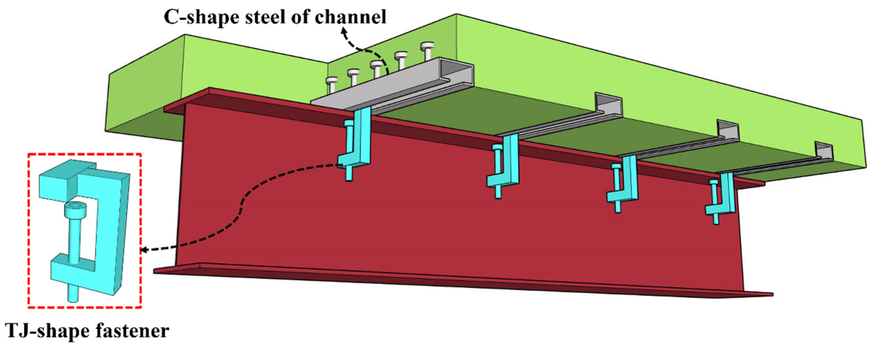
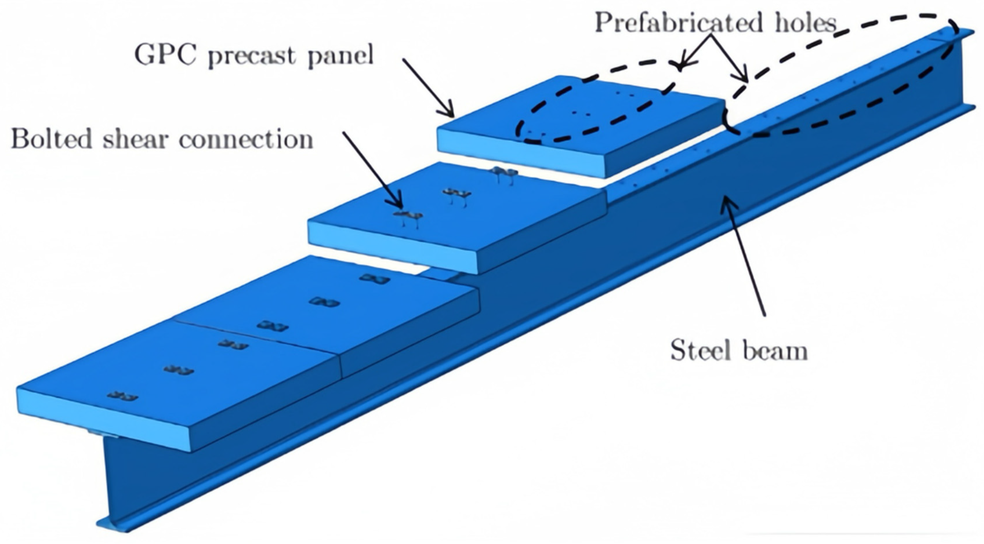
In research related to demountable concrete beams, various types of demountable shear connectors have exhibited different effects on the performance of concrete beams. Based on their advantages (i.e., demountability, partial replaceability, and reusability), demountable shear connectors can be broadly classified into two categories: assembled bolt tightening-bearing shear connectors (
Figure 1) [
14,
15,
16] and assembled full-friction shear connectors [
17], as shown in
Figure 2.
The assembled bolt tightening-bearing shear connector is a type of connector designed to resist the horizontal shear force between the beam and the slab using high-strength bolts, as shown in
Figure 1 [
18]. This type of connector offers several advantages: large stiffness, high shear capacity, and ease of removal. In Su et al. [
19] and Luo et al.’s investigations [
20], composite beams (
Figure 3) equipped with this type of shear connector exhibited good deformation capacity and high post-yield capacity, enhancing the overall performance of the structure. As such, the adoption of assembled bolt tightening-bearing shear connectors not only addresses the challenges associated with the demountability and recyclability of concrete beam structures but also improves the efficiency and flexibility of construction and maintenance processes.
For the assembled full-friction shear connectors, demountable connectors are employed to achieve the connection between the steel beam and the precast concrete slab, utilizing friction force to resist horizontal shear forces, as shown in
Figure 2 [
17]. Bradford et al. [
21] (
Figure 4) and Ataei et al. [
22] found that the pre-tightening force of the bolts provided sufficient friction between the prefabricated slab and the steel beam, ensuring effective load transfer and structural integrity. Consequently, this type of shear connector exhibits enhanced ductility, and its initial stiffness is high, which reduces slip at the steel–concrete interface during utilization in engineering and improves the overall stiffness of the composite beam.
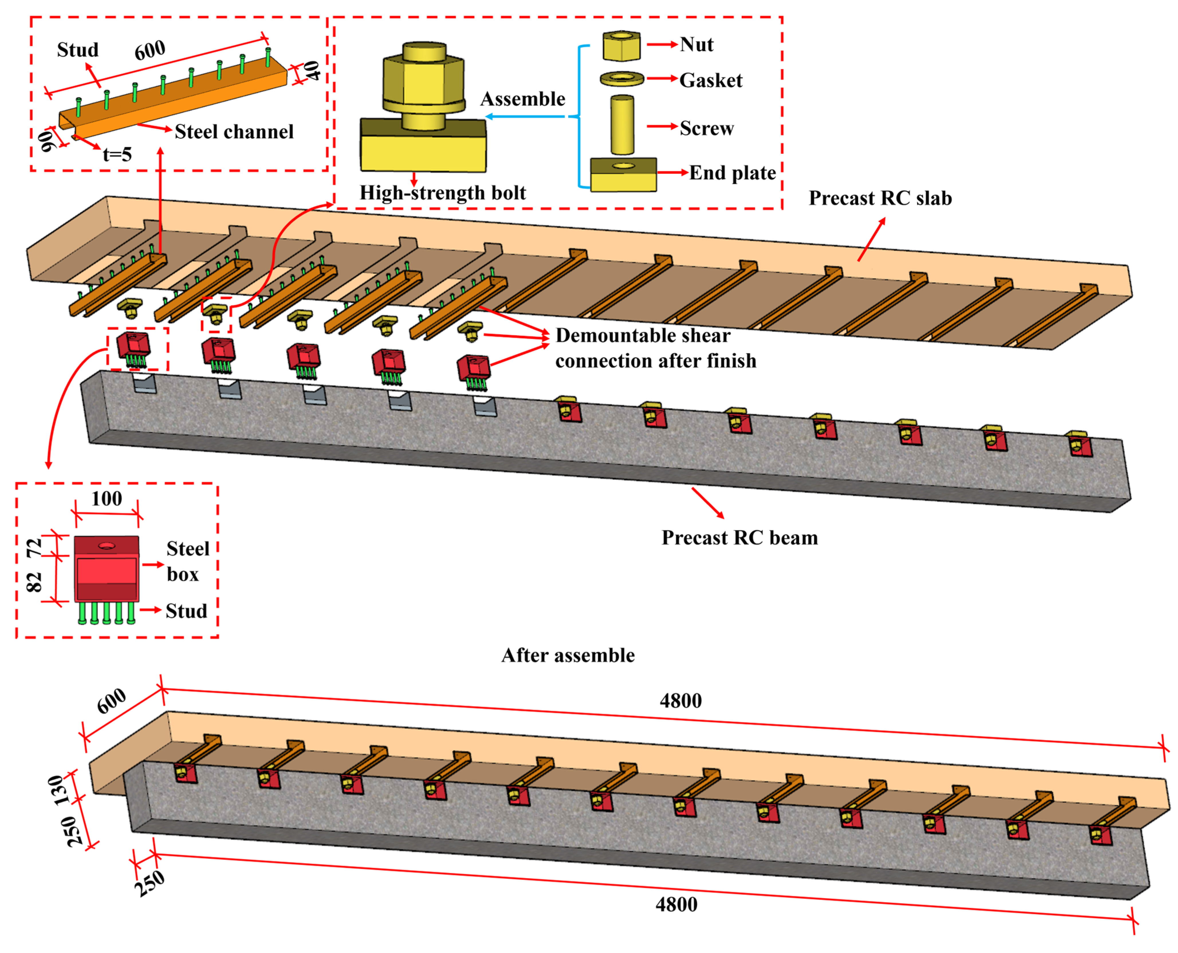
Although the demountable connectors proposed in previous studies can be reused, their shear performance is sensitive to installation torque and surface treatment; they usually require complex installation or cannot be completely disassembled after maintenance; and fatigue performance reduction or slippage may occur before shear transmission. Moreover, the existing detachable connectors are focused on the steel beam–concrete slab, and there are few demountable connections between the concrete beam and concrete slab. To address this, this study proposes a fully dry connection method between concrete beams and slabs to facilitate the complete demountable replacement of beams and slabs, as shown in
Figure 5. This composite beam is composed of studs, steel boxes, steel channels, and high-strength bolts. Steel boxes are embedded in the concrete beams, while steel channels are embedded in the concrete slabs. The shear connectors combine the steel channels and steel boxes using high-strength bolts. Additionally, this shear connector design has the advantage of keeping the bolts external to the concrete matrix. This arrangement significantly enhances maintainability, as post-test assessments have confirmed that replacing only the bolts suffices to reinstate full functionality. In general, the connection method proposed in this study is completely detachable and does not damage the plate or beam; there is improvement in fatigue resistance, not just friction; replacement and reinstallation are easier; and there is improved construction flexibility and sustainability of modular systems.
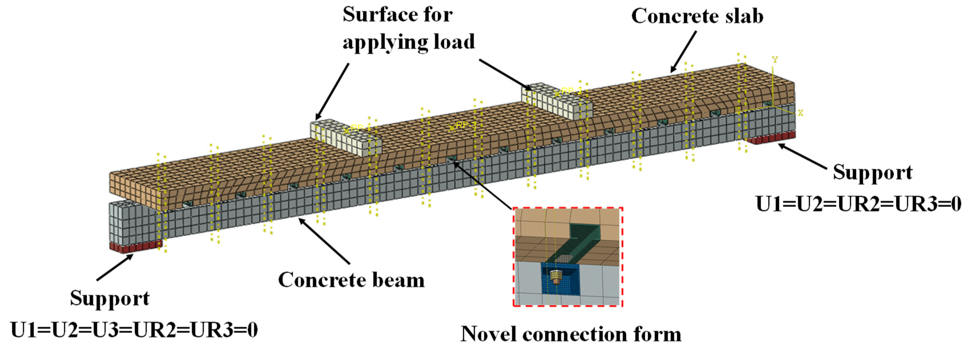
To investigate the flexural performance of this new type of fully dry connection method, numerical analysis was employed to investigate the new demountable concrete beams, which was verified using a previous experimental test. The influence of various parameters, such as material properties, connection types, and beam dimensions, on the flexural performance of the concrete beams was observed. Additionally, formulas for calculating the ultimate flexural moment of the demountable concrete beam under different conditions are developed.
3. Results and Discussion
3.1. Effects of Various Parameters
3.1.1. Effect of Bolt Diameter
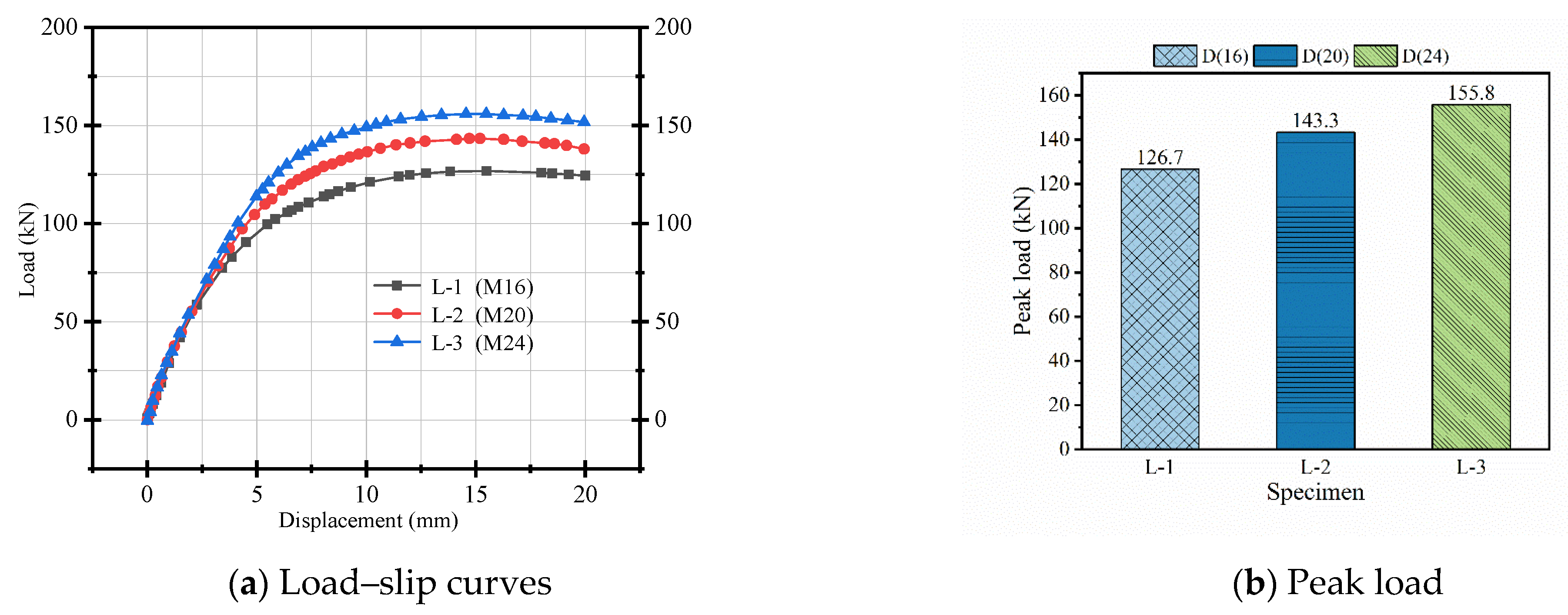
As shown in
Table 4 and
Figure 11, when the bolt diameter increases from 16 mm to 24 mm, the peak load increases by 23%, the yield load by 26%, and the flexural stiffness by 20%. This improvement is attributed to the larger bolt diameter, which enhances the pre-tightening force and thereby improves the cooperative interaction between the concrete beam and the slab. However,
Table 4 also indicates that the ductility coefficient of the demountable concrete beam decreases with increasing bolt diameter, likely due to reduced beam deformation. From a structural mechanics perspective, this leads to a more integrated response and delays the onset of connector deformation and interface separation. However, the ductility coefficient decreases with increasing bolt diameter, likely due to the reduced deformation capacity at the connection; the stiffer bolts limit rotational freedom and plastic deformation, resulting in a more brittle failure mode. Therefore, while larger bolts enhance strength and stiffness, they may compromise energy dissipation. For design applications—particularly in seismic regions or deformation-critical systems—a balanced selection of bolt diameter is essential to optimize both strength and ductility.
3.1.2. Effect of Bolt Strength
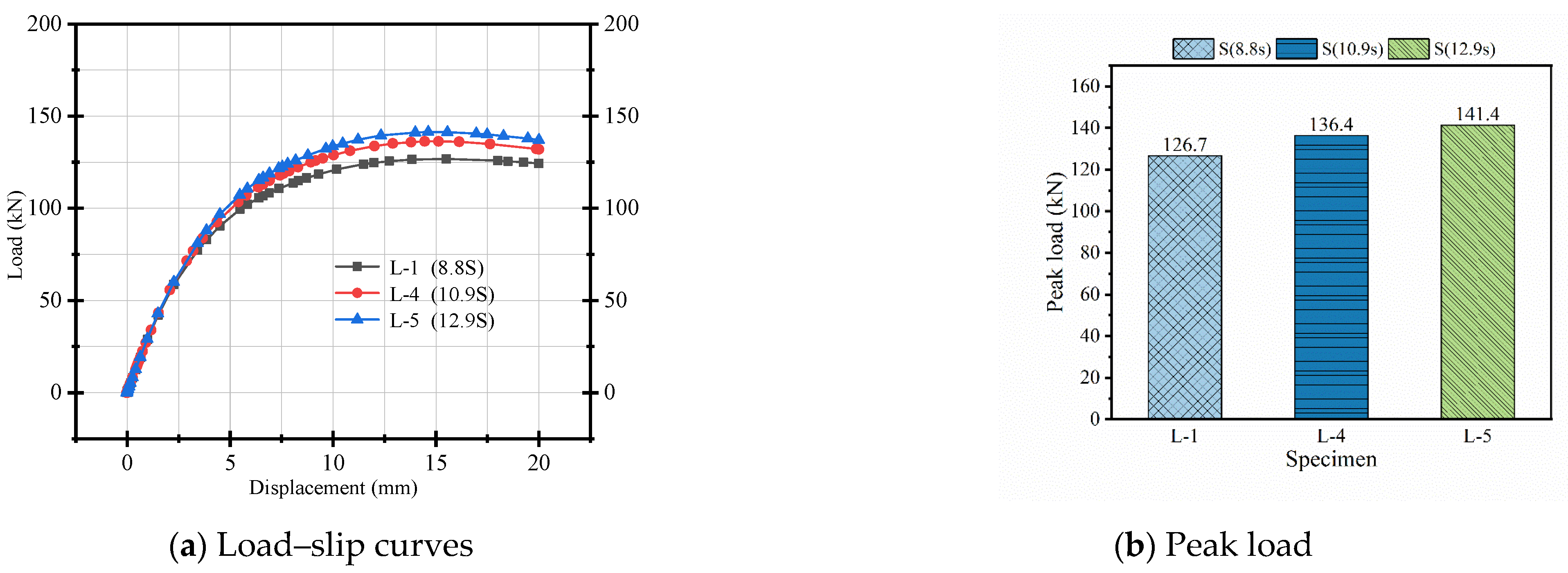
Similarly, when the bolt strength grade increases from 8.8 S to 12.9 S, the peak load increases by 12%, the yield load increases by 13%, and the flexural stiffness increases by 7%, as shown in
Figure 12. The underlying reason is that a higher bolt strength results in greater bolt preload, which enhances the friction resistance between the beam and the plate, thereby improving the integrity of the component and its flexural performance. From
Table 4, it is evident that the ductility coefficient of the demountable concrete beam decreases as the bolt strength grade increases. This is because a higher strength grade bolt has superior shear bearing capacity. Consequently, the system exhibits a stiffer but less deformable behavior, resulting in reduced energy dissipation capacity. From a design standpoint, while high-strength bolts enhance mechanical performance, their use may need to be moderated in structures requiring significant ductility or post-yield deformation capacity.
3.1.3. Effect of Steel Channel Spacing
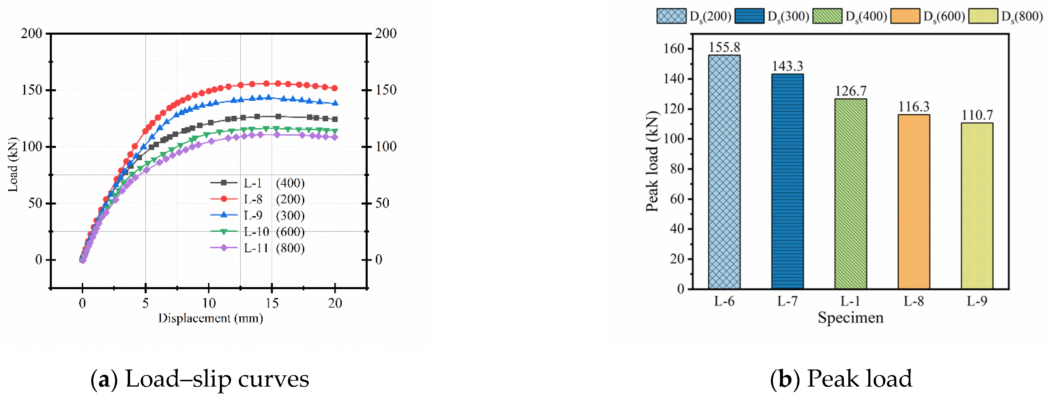
As shown in
Figure 13, when the channel distance increases from 200 mm to 800 mm, the peak load decreases by 29%, the yield load decreases by 32%, and the flexural stiffness decreases by 32%. This reduction is likely due to the increased channel spacing reducing the number of connectors, which weakens the cooperative working ability between the concrete beam and the plate. With fewer connectors, local slip and interface separation become more pronounced under load, leading to decreased stiffness and earlier yielding. Additionally, the wider spacing allows for greater differential deformation between the slab and beam, further reducing structural integrity. From a design perspective, these results highlight the importance of maintaining an appropriate connector spacing to ensure effective force transfer and to preserve both strength and stiffness in demountable composite systems.
3.1.4. Effect of Concrete Beam Strength
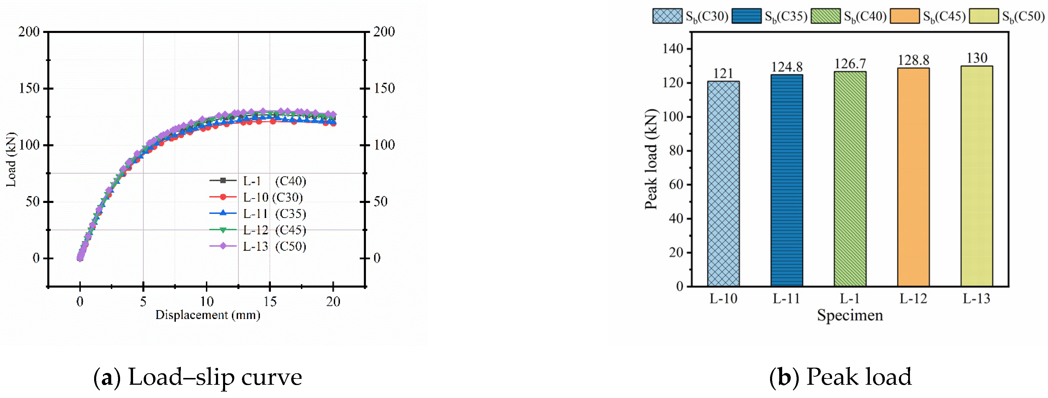
When the concrete beam strength increases from C30 to C50, there is a 7% increase in peak load, a 13% increase in yield load, and a 6% increase in flexural stiffness, as illustrated in
Figure 14. This limited improvement is mainly due to the fixed bolt diameter and constant pre-tightening force, which restrict the enhancement of shear force transfer in the bolted connections. As a result, the increase in concrete strength alone does not effectively promote the interaction between the concrete beam and slab. With the unchanged bolt parameters, the connection’s ability to transfer load remains constrained, limiting the overall structural performance gains. From a design perspective, this indicates that merely increasing concrete strength is insufficient to significantly improve composite action, and attention should also be paid to optimizing connector properties to achieve better force transfer and structural behavior.
3.1.5. Influence of Slab Strength
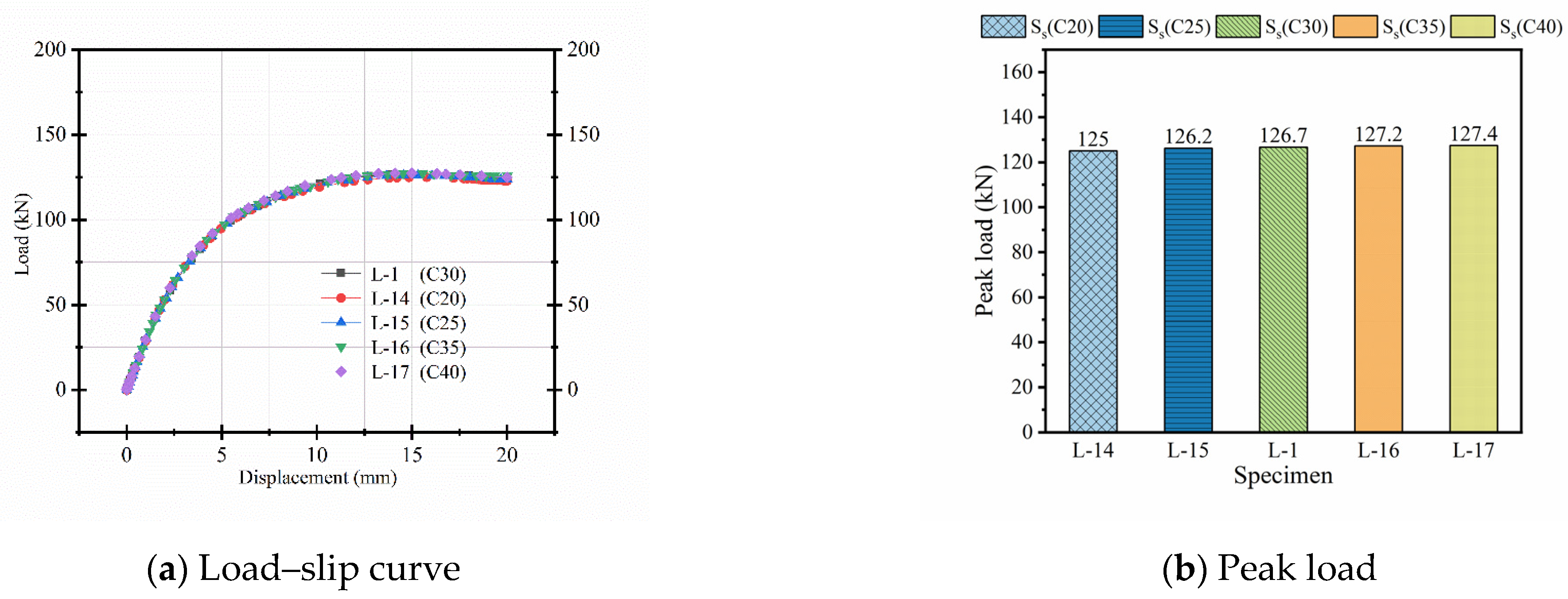
When the concrete slab strength increases from grade C20 to C40, the peak load and yield load each increase by 2%, and the flexural stiffness improves by 10%, as shown in
Figure 15. This limited improvement is primarily due to the fixed bolt diameter and constant pre-tightening force, which do not scale proportionally with the enhanced slab strength. Structurally, although the slab’s material strength increases, the shear transfer capacity at the bolted interface remains constrained by the connector properties, limiting the effectiveness of the composite action. Consequently, the shear force transfer efficiency within the bolted connections remains largely unchanged, restricting notable gains in load-bearing capacity. From a design perspective, this indicates that simply increasing slab strength without corresponding adjustments to connector parameters yields minimal improvements in the overall structural performance of the composite system.
3.1.6. Influence of Concrete Slab Thickness
As the concrete slab thickness increases from 80 mm to 180 mm, the peak load shows a 46.3% increase, the yield load rises by 44.5%, and the flexural stiffness improves by 116.1%, as illustrated in
Figure 16. This substantial enhancement is primarily due to slab thickness being a critical factor influencing flexural capacity. Structurally, a thicker slab increases the effective depth of the composite section, thereby enlarging the internal lever arm and enhancing the moment of inertia. This results in greater bending resistance and improved stiffness. Furthermore, the increased slab thickness enhances the confinement of the steel beam flange, reducing local buckling and improving load distribution. Consequently, the composite action between the beam and slab is significantly strengthened, leading to higher load-bearing capacity and improved deformation performance. From a design perspective, optimizing slab thickness is an effective approach to markedly enhance the structural performance of composite beam–slab systems.
3.1.7. Influence of Flange Width of Concrete Slab
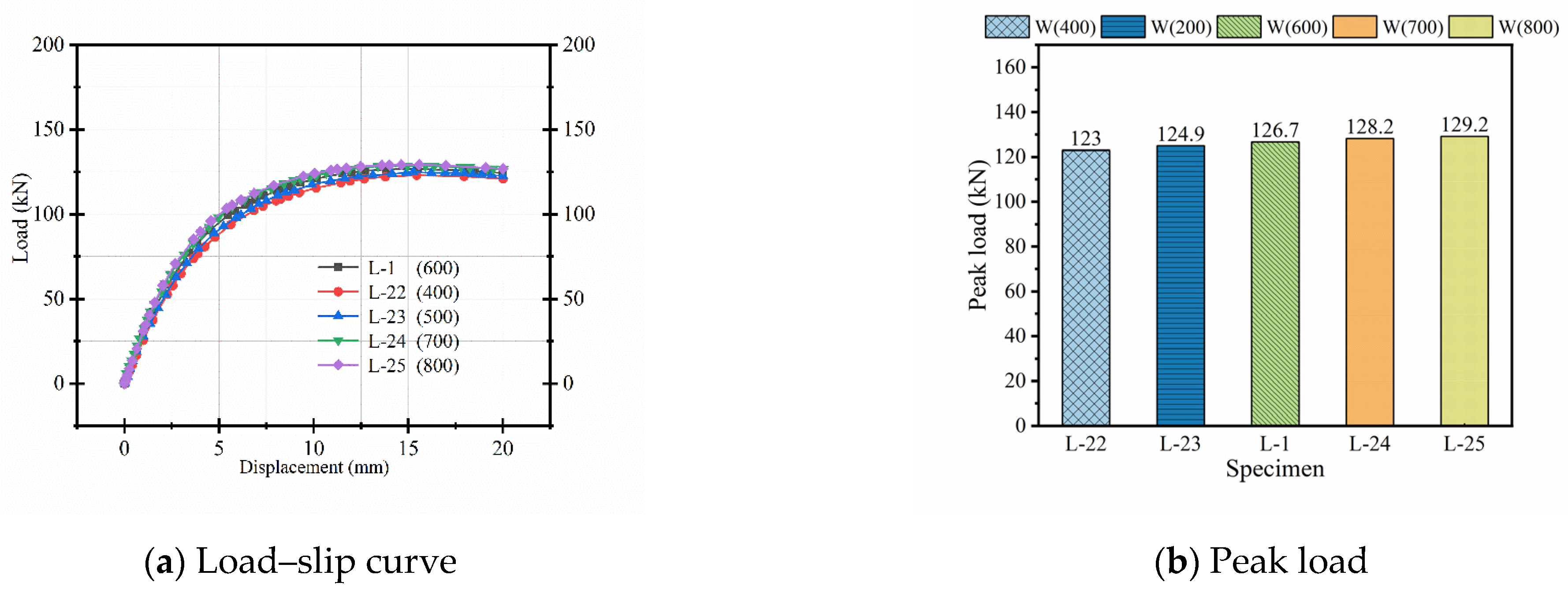
When the flange width of the concrete slab is increased from 400 mm to 800 mm, the peak load increases by 5%, the yield load by 3.1%, and the flexural stiffness by 26.3%, as depicted in
Figure 17. This improvement occurs because widening the flange mainly increases the slab’s effective cross-sectional area, thereby enhancing its bending stiffness. However, since the increase in width does not substantially affect the slab’s load-bearing capacity or the internal force distribution, the gains in peak and yield loads are relatively limited. Structurally, a wider flange provides greater resistance to deformation and reduces stress concentrations, which contributes to improved stiffness and delays the onset of yielding. From a design viewpoint, increasing flange width is an effective means to improve stiffness and serviceability, though its impact on ultimate strength is comparatively modest.
3.2. Disassembly Analysis
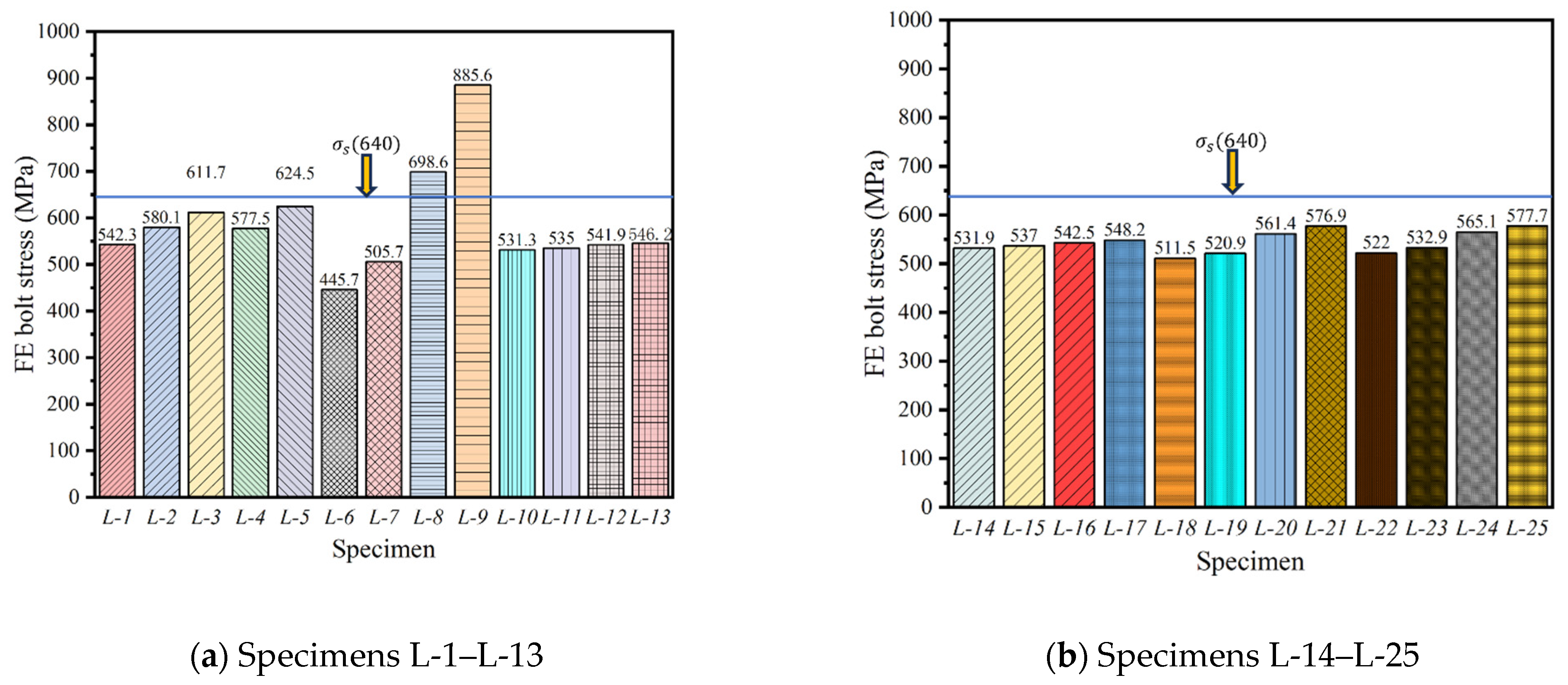
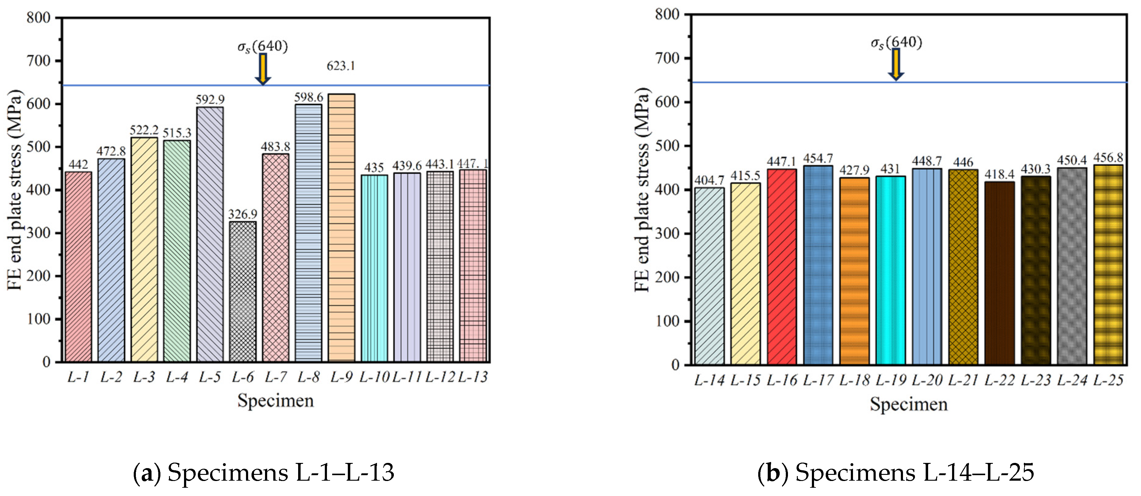
To evaluate the disassembly performance of the flexural test specimen, a stress analysis was conducted on the shear connector with the maximum stress in the loaded specimen. If the maximum stress in the bolt and end plate does not reach the yield stress of the steel member, it indicates that the component has not undergone plastic deformation. Consequently, the flexural test piece can be disassembled normally under standard service loads, indicating good disassembly performance, which aligns well with practical project applications.
Figure 18 and
Figure 19 show the maximum bolt stress and end plate stress of the flexural test piece, respectively. The analysis reveals that the stress in all test pieces did not reach the yield strength of either the bolt or the end plate, except for L-8 and L-9. The L-9 test piece significantly exceeded its yield strength, with a bolt stress value of 885 MPa and an end plate stress value of 620 MPa. This suggests that the steel channel spacing significantly impacts the disassembly performance of the test piece. As the steel channel spacing increases, the number of connectors decreases, causing each bolt to bear more stress, which in turn increases the stress on the end plate. Overall, the stress in the bolts and end plates of the vast majority of specimens did not reach their yield strength, neither the bolt nor the end plate underwent plastic deformation, allowing for normal disassembly of the test piece.
In addition to stress-based assessments, several practical considerations may affect the feasibility of disassembly and reuse in real applications. For instance, bolt access during field assembly or disassembly can be limited by surrounding structural geometry, which should be addressed in design detailing, Specifically, the bolt holes in the steel box were designed larger than the bolt diameter to allow for construction tolerances and ease of installation. Likewise, field tolerances such as bolt hole misalignments or uneven bearing surfaces may hinder precise fit-up and require on-site adjustments.
Another important factor is bolt fatigue due to multiple reuse cycles. Although this study does not incorporate fatigue modeling, repeated installation and removal may degrade bolt performance over time. This aspect is beyond the scope of the current work but is recognized as a critical topic for future investigation.
3.3. Analysis of Limitations
While the proposed finite element and theoretical models show good accuracy and consistency with test results, several limitations should be acknowledged:
(1) The parametric study is confined to slab thicknesses ranging from 80 mm to 180 mm. The model may not be directly applicable to configurations beyond this range.
(2) The reinforcement ratio in the concrete slab was assumed within typical design limits (e.g., 0.3–1.5%). Slabs with very high or low reinforcement may exhibit different cracking patterns or failure modes not captured by the current model.
(3) The model does not account for long-term effects such as fatigue, bolt loosening, or creep and shrinkage of concrete, which may influence the reusability and performance over repeated cycles.
(4) The steel box contribution is neglected in the theoretical model, which is acceptable within the studied configurations. However, for designs with larger or stiffer embedded steel elements, this simplification may need to be revisited.
These limitations suggest that while the model provides useful guidance for design and analysis, care should be taken when applying it outside the calibrated parameter range, and future work is encouraged to address durability and fatigue behavior for reuse scenarios.
4. Flexural Capacity of Concrete Beam
Under uniform loading conditions, the theoretical stress distribution in the concrete’s compression zone is replaced with an equivalent rectangular stress distribution, as specified in GB 50010-2010 [
24]. Since the steel box is located closer to the neutral axis, it provides minimal tensile and compressive stress. Consequently, the steel box does not significantly contribute to the flexural capacity of the concrete beam, and its influence on the flexural capacity of concrete beam is therefore neglected in the plane section assumption.
Based on the location of the plastic neutral axis, the flexural capacity of the concrete beam is categorized into three distinct cases:
(1) As shown in
Figure 20a, when the plastic neutral axis is located within the concrete slab and the beam is subjected to a positive flexural moment, the following model is established:
where
is the equivalent rectangular stress diagram coefficient, and the value is 1.0;
is the design value of compressive strength of concrete slab;
is the width of concrete slab; x is the height of concrete compression zone in the equivalent rectangular stress diagram;
is the design value of tensile strength of steel bar;
is the cross-sectional area of the longitudinal reinforcement in the concrete beam;
is the design value of positive flexural moment; and
is the effective height of the cross section.
(2) As shown in
Figure 20b, when the plastic neutral axis is located within the concrete beam, and the beam is subjected to a positive flexural moment, the following model is established:
where
is the thickness of concrete slab,
is the design value of compressive strength of concrete beams,
is the width of concrete beam,
is the distance from the center of the section of the compression zone of the concrete slab to the center of the section of the compression zone of the concrete beam, and
is the distance between the resultant force of the cross-section stress of the tensile longitudinal reinforcement and the cross-section centroid of the compression zone of the concrete beam.
(3) As shown in
Figure 20c, when the beam is subjected to a negative flexural moment, the following model is established:
where
is the design value of negative flexural moment, and
is the cross-sectional area of the longitudinal reinforcement in the concrete slab.
To validate the theoretical model derived above, the comparison of ultimate flexural moment between the theoretical model and the numerical results is made, as shown in
Table 5. Clearly, the developed theoretical model is accurate for the prediction of the ultimate flexural moment concrete beam. The average ratio of the predicted value to the simulation result is only 1.01, and the standard deviation and the coefficient of variation are 0.09 and 8.91%, respectively.
5. Conclusions
In this study, a new type of demountable shear connector is proposed, and the flexural performance of concrete beam is then analyzed and evaluated using numerical analysis, which is then validated by previous tests. The following conclusions can be drawn:
(1) The peak load is significantly influenced by several factors, such as bolt diameter, bolt strength, channel spacing, and concrete slab thickness, while concrete beam strength, concrete slab strength, and slab flange width have only a minimal effect. Similarly, flexural stiffness is notably impacted by bolt diameter, channel spacing, concrete slab strength, slab thickness, and flange width, whereas bolt strength and concrete beam strength have a relatively minor influence.
(2) The stress in the bolts and end plates of most specimens remained below their yield strength, preventing plastic deformation in both components and allowing for easy disassembly of the test pieces.
(3) A theoretical model for calculating the ultimate flexural moment of demountable concrete beams under different conditions is proposed, and it agrees well with numerical results as the average ratio of the predicted value to the simulation result is only 1.01, and the standard deviation and the coefficient of variation are and 8.91%, respectively.

