1. Introduction
The vertical jacking method has gained increasing application in shield tunnel construction owing to its minimal spatial footprint, abbreviated construction duration, and reduced environmental impact. This technique employs hydraulic jacking equipment to advance pipelines through overlying soil strata, thereby creating functional shafts for applications including shield ventilation, water extraction, maintenance operations, and ancillary activities [
1,
2]. Nevertheless, the mechanical response of tunnel segments during vertical jacking manifests considerable complexity, characterized by substantial structural deformation and significant stress perturbations.
In addressing the engineering challenges associated with vertical jacking within shield tunnels, limited scholarly investigations have been undertaken. Current research has examined the mechanical characteristics of segments during jacking operations, with numerical analyses elucidating internal forces acting upon joint bolts. Comparative assessments against field measurements underscore the necessity for enhanced design methodologies [
3]. Preventive measures addressing mechanical responses at the tunnel invert during vertical jacking construction warrant formulation [
4]. Additionally, three-dimensional finite element analyses have been employed to evaluate deformation characteristics of segments and circumferential seams induced by shield tunnel jacking operations [
5]. Further clarification is required regarding the damage mechanisms, extent, and progression within overlying soil strata during jacking, potentially achievable through particle flow simulations and physical model testing [
6,
7]. Design and construction practices have incorporated studies on jacking force and reaction force computations, encompassing internal shield tunnel deformations and vertical displacement variations [
8,
9].
Notably, a paucity of research addresses the evolutionary development of vertical jacking reaction forces and their concomitant mechanical impacts on tunnel structures. During vertical jacking construction, the reaction forces exert substantial influence upon the tunnel’s basal segments, inducing structural deformations and stress disturbances that fundamentally alter the global stress state.
A specialized model testing apparatus simulating vertical jacking for shield tunnel shafts was developed, based on specifications from a water conveyance tunnel inspection well prototype. Experimental investigations were conducted to delineate the distribution characteristics of reaction forces throughout the jacking process and to characterize the stress–deformation behavior of the shield tunnel structure. Particle flow method simulations computed tunnel deformations during vertical jacking, with subsequent validation against experimental results. Furthermore, the efficacy of varying reinforcement ranges in tunnel deformation mitigation was assessed, leading to the proposal of applicable engineering control strategies for deformation management.
2. Model Test Scheme Design
2.1. Experimental Materials and Similarity Ratio
This study investigates a ventilation and inspection shaft for a shield tunnel with an overburden thickness of approximately 8 m. The test soil layer was obtained from field investigation samples, primarily comprising common shallow cohesive soils found in Guangzhou. These samples were collected from the construction site and subsequently remolded under controlled laboratory conditions for mechanical property testing. Laboratory test results indicate that the model test soil layer possesses a unit weight (γ) of 18.5 kN/m3, cohesion (c) of 6.6 kPa, an internal friction angle (φ) of 27.7°, and a compression modulus (Es1–2) of 5.65 MPa.
The model test tunnel was designed based on a preliminary shield tunnel configuration featuring a 6 m diameter and an 8 m overburden. The jacking pipe model has a diameter of 1.4 m, a wall thickness of 20 cm, and a segment length of 1.0 m. Both the model shield segment (
Figure 1) and the jacking pipe were fabricated from nylon material. Shield ring joints were simulated using bolts and polyethylene (PE), while longitudinal joints were modeled via the lateral slot method, consistent with references [
10,
11,
12]. Applying similarity principles, primary test parameters were established, encompassing prototype tunnel characteristics and model geometric and physical indicators (
Table 1). Segment joint parameters were derived from the literature [
13,
14,
15], with joint dimensions determined using the equivalent stiffness coefficient similarity ratio.
2.2. Experimental Device and Plan
The experimental apparatus comprises a model test box, a jacking system, and a monitoring system (
Figure 2).
- (1)
The study employed a large-scale model box fabricated from transparent acrylic, measuring 60 cm (length) × 110 cm (width) × 180 cm (height). The base consisted of 2 cm thick glass, while the side walls were constructed from 1.5 cm thick glass. Openings were created on both lateral walls, aligned with the shield tunnel model’s axis and corresponding to the tunnel’s outer diameter. The centerline of these openings coincided with the tunnel axis to accommodate the installation of jacking devices, testing apparatus, and data acquisition instruments. A 5 cm × 5 cm grid was inscribed on the jacking side wall to facilitate displacement observation and measurement. Additionally, three 20 mm thick high-strength glass hoops were uniformly distributed circumferentially around the model box to ensure sufficient structural integrity to withstand the applied test loads.
- (2)
The jacking system consists of a reaction diffusion block, a thrust frame, and a hydraulic jack. The 20 cm wide reaction diffusion block, fabricated from the same material as the shield tunnel segment, is rigidly affixed to the segment base. The thrust frame, an open circular structure fabricated from rebar, serves dual functions: providing temporary support for the jacked pipe section and facilitating the placement of subsequent pipe sections. The assembly incorporates a TRC108 model hydraulic jack, with a height of 28.8 cm, a diameter of 6 cm, and a maximum stroke of 20.3 cm.
The monitoring system integrates displacement monitoring points embedded within the soil layer, strain gauges affixed to the shield tunnel lining, displacement transducers, and jack force sensors. Displacement monitoring points were interconnected using plastic sheets and thin wooden strips. High-definition digital cameras and camcorders recorded displacement monitoring point variations at five-second intervals throughout the jacking process. Strain gauges and displacement transducers collected data on shield tunnel lining stress and deformation during jacking, with particular emphasis on the opening ring deformation. Monitoring points were primarily positioned on the opening ring O1 and the adjacent rings N1 to N3.
During the experimental procedure, the model box is initially positioned within the test soil and prepared via the layered compaction method. Each soil layer is uniformly distributed throughout the model box, compacted to a height of 5 cm using a flat-faced rammer, and subsequently leveled with a straightedge. Displacement measuring points are embedded at predetermined locations during the soil placement process. A thin layer of lubricating oil is applied to the contact surfaces between the plastic sheet and the model box at the designated monitoring points. During the pipe jacking procedure, the jacking height is determined based on the scale affixed to the front face of the model box.
3. Analysis of Jacking Reaction Force Test Results
When the shield is lifted vertically, the jacking reaction force mainly stems from the soil weight within the shear failure zone. This force incorporates shear interactions at the sliding surface between soil layers, the self-weight of the jacking pipe segment, and frictional resistance along the pipe’s side wall against the surrounding soil. High-definition image feature points are employed to establish the jacking height, with pressure sensor readings logged at capture times.
Figure 3 displays the reaction force curve for the shield shaft’s vertical jacking across different heights.
As illustrated in
Figure 3, the vertical jacking reaction force demonstrates pronounced nonlinear characteristics throughout its development. This force evolution can be delineated into three distinct phases: an initial increase, a subsequent decrease, and eventual gradual stabilization. During the initial phase, as the jacking height attains 0.4 m (h/20), the reaction force experiences a significant increase. At this stage, the overlying soil layer becomes subjected to compression, culminating in a maximum pressure of 377 kPa at the diffusion block. The subsequent phase, corresponding to jacking heights ranging from 0.4 m to 1.6 m (h/20 to h/5), is characterized by shear failure within the overlying soil, resulting in the formation of a sliding surface and a consequent rapid decrease in reaction force. Thereafter, as jacking height increases further, the reaction force continues to diminish at a reduced rate, ultimately stabilizing at approximately 202 kPa.
4. Analysis of Segment Displacement and Stress Results
4.1. Results Monitoring Point Layout
To characterize the displacement response of the opening segment and adjacent structures during vertical jacking, displacement gauges and strain gauges were installed at distinct locations within the specimens (
Figure 4).
4.2. Analysis of Transverse Convergence Deformation of Segment
Figure 5 presents the incremental displacement of segments at varying jacking stages. A positive deformation value denotes outward segment deformation, whereas a negative value indicates inward segment deformation. Further,
Figure 6 documents the segment deformation process throughout the jacking procedure.
The figure illustrates that segment convergence displacement undergoes four distinct stages: substantial increase, rapid decrease, gradual decline, and eventual stabilization, each corresponding to increasing jacking height. Initially, segment ring deformation is most pronounced, particularly during initial jacking operations. As the jacking force intensifies, the tunnel experiences increased settlement at both the crown and invert, resulting in significant waist convergence compared to the initial state. Following overlying soil shear failure, the jacking force decreases sharply, thereby inducing invert rebound while the waist deforms outward. As the jacking height increases further, the invert exhibits continued rebound, the waist undergoes outward expansion, and the crown experiences slight uplift until segment deformation stabilizes during later stages. This behavior aligns with the jacking force distribution presented in
Figure 3.
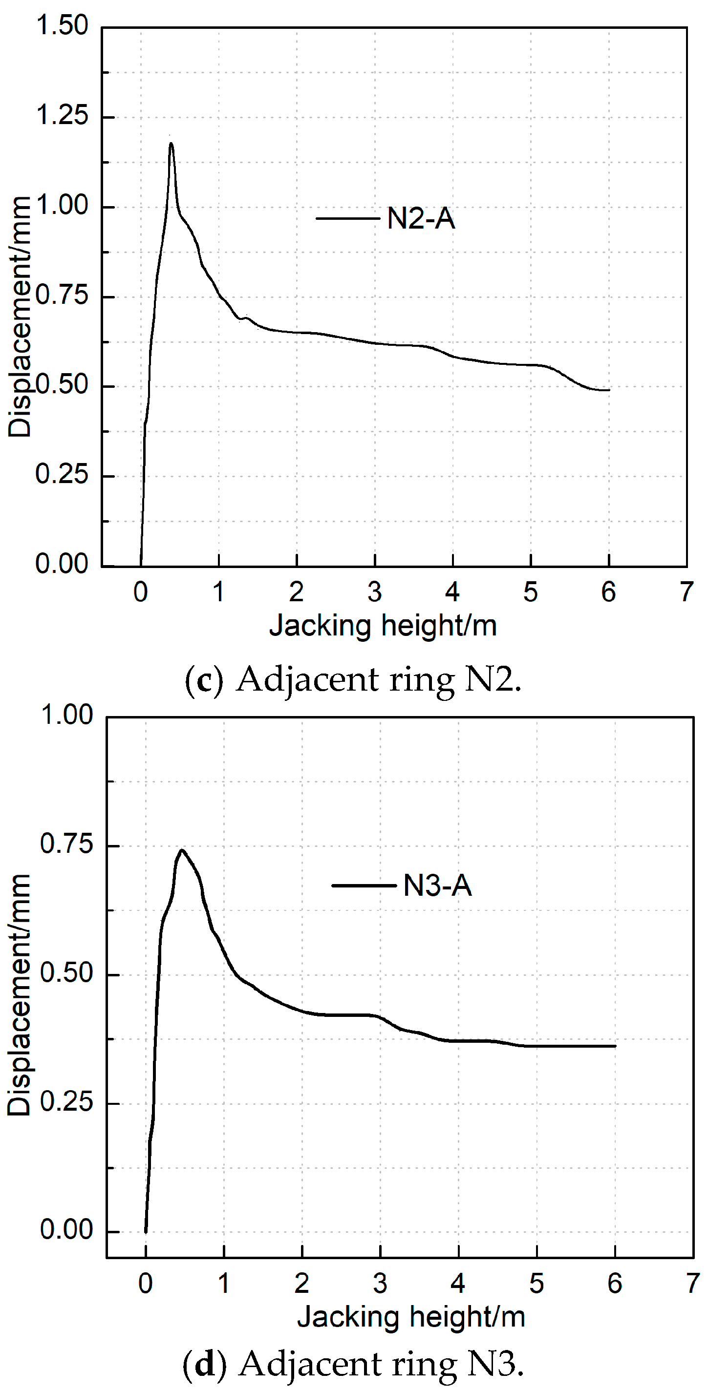
Under vertical jacking force influence, the opening ring (O1) and adjacent segments (N1 to N3) primarily exhibit vertical deformation responses. Recorded maximum settlements at the base measure 2.55 mm, 1.68 mm, 1.20 mm, and 0.75 mm, respectively. The opening ring experiences notably greater deformation than adjacent rings, with N3 displacement measuring only 44.6% of N1 displacement, indicating a more than twofold difference. This observation indicates that the jacking force influence zone encompasses the opening ring and its two adjacent rings. Additionally, the opening ring’s maximum horizontal displacement is 1.18 mm, substantially less than its vertical displacement. Consequently, segment vertical displacement characteristics warrant primary consideration when designing reinforcement strategies during jacking operations, with particular emphasis on vertical reinforcement measures.
4.3. Deformation Analysis of Segment Joint
- (1)
Segment opening
Based on the findings depicted in
Figure 5, the longitudinal settlement of the shield tunnel under the most unfavorable jacking conditions (presented in
Figure 7) was examined. The tunnel structure was represented by a longitudinally discontinuous beam model. The imposition of jacking reaction forces generates longitudinal bending deformation, leading to maximum joint opening within opening ring pairs. Simultaneously, abrupt longitudinal load transitions induce segment dislocation, causing maximum displacement between the opening ring and its adjacent ring. Consequently, the assessment of segment joint deformation concentrated on measurements obtained from the bottom joint K1 (located within opening ring pairs) and bottom joint K2 (situated between the opening ring and an adjacent ring).
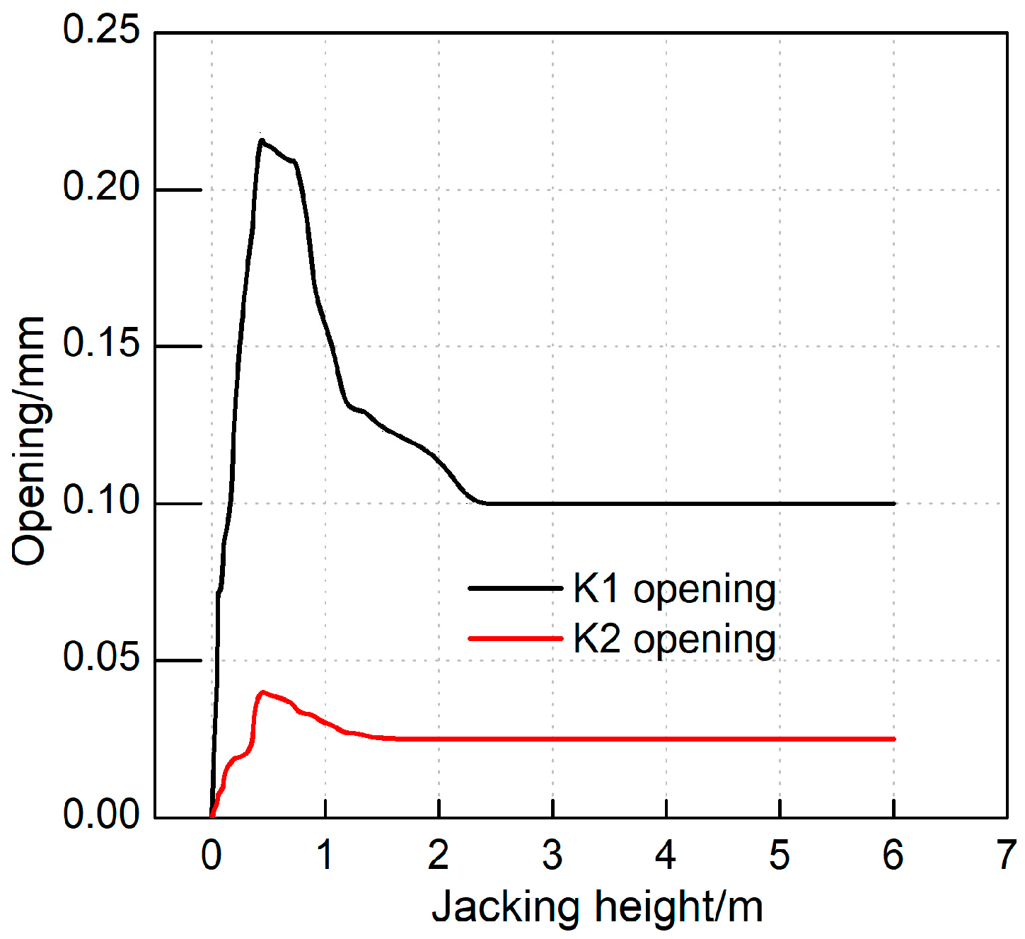
Figure 8 displays the distribution of the segment ring seam opening amount relative to different jacking heights. A positive value indicates the segment is relatively open, while a negative value denotes closure. The seam opening trend mirrors the development of jacking force and segment displacement: initially increasing, subsequently decreasing, and finally stabilizing. The maximum recorded opening is 0.22 mm, observed at the bottom of the K1 joint—the junction between the two open segments in the middle ring. At this location, the outer side of the segment annular seam is open. Conversely, the maximum opening at the K2 joint is only 0.04 mm, equivalent to 18% of the opening at the open ring. Unlike displacement effects, the opening significantly impacts longitudinal transmission attenuation. Tunnel displacement primarily stems from segment structure deformation, with annular seam joint deformation contributing minimally.
- (2)
Segment dislocation
Based on the preceding analysis of segment dislocation characteristics, joint D1—located between the opening ring O1 and the adjacent standard ring N1—along with two dislocation deformation measurement points at joint D2 (situated between rings N1 and N2), were identified. Staggered platform deformation monitoring was accomplished by measuring the vertical displacement difference between two ring sections using dial gauges positioned at their bases (
Figure 9).
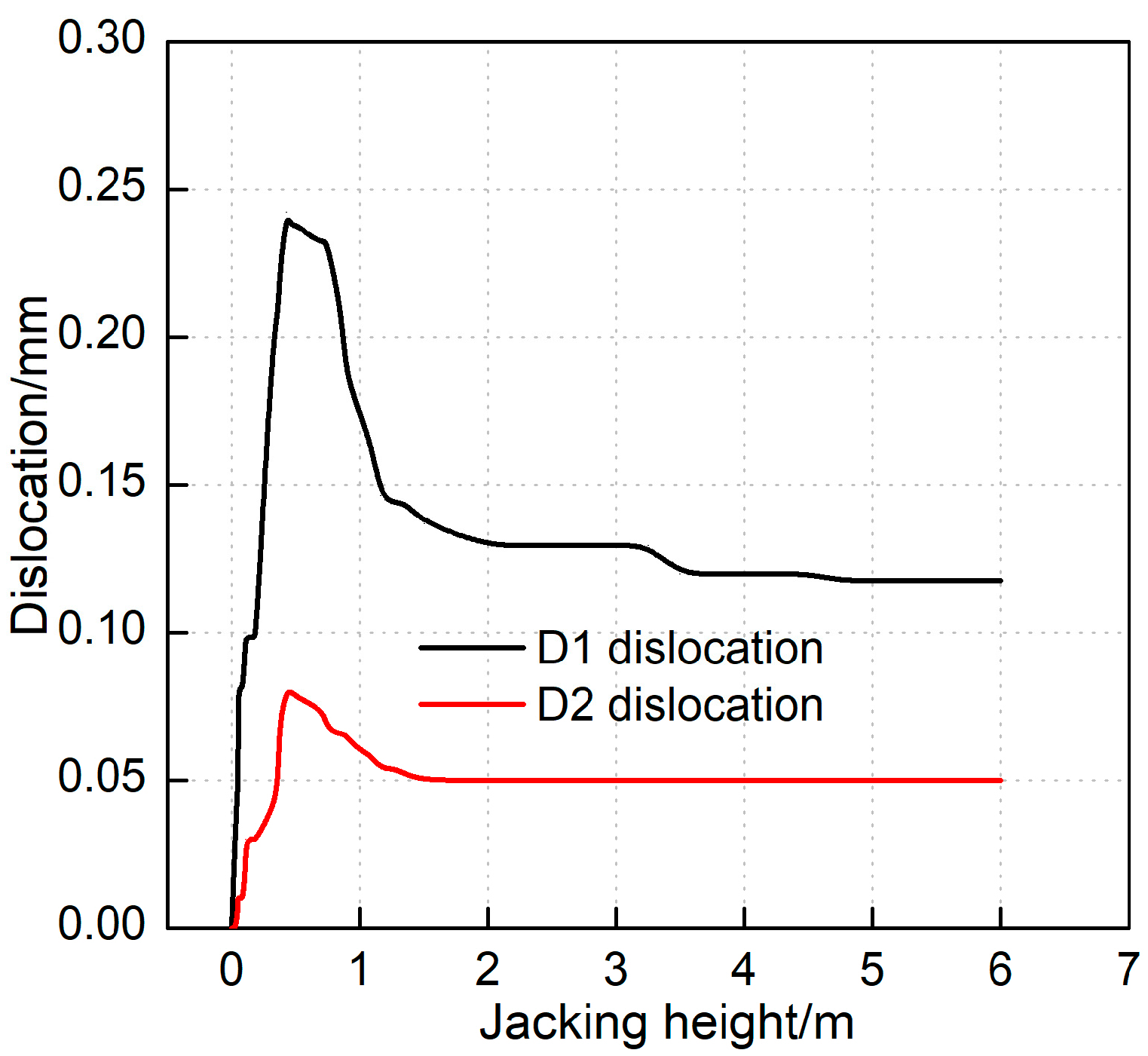
Increasing the jacking height elevates the jacking reaction force, accentuating the load differential between the opening ring and the adjacent ring. Annular joints D1 and D2 exhibited rapid dislocation increases followed by significant decreases upon load reduction. Ultimately, dislocation values gradually diminished and stabilized. Maximum dislocations occurred at peak jacking reaction force: 0.24 mm at D1 and 0.08 mm at D2, representing approximately 33% of D1’s dislocation. This behavior mirrors the opening response, demonstrating notable longitudinal influence attenuation. The limited influence range contributes minimally to tunnel displacement. Longitudinal opening test results confirm that segment openings remain below the joint bolt’s elastic limit deformation value of 1.11 mm [
16]. This measurement is substantially lower than the 2 mm control value for subway ring seam openings [
17], while segment dislocations are markedly below the 3 mm control threshold [
18]. Additionally, these test results corroborate longitudinal opening and dislocation assessments derived from lateral displacement measurements.
4.4. Damage Analysis of Segment Structure
To investigate the potential for damage to the shield segment during the vertical jacking process, 23 stress measurement points were symmetrically positioned within the opening ring and on the inner side of the two adjacent rings.
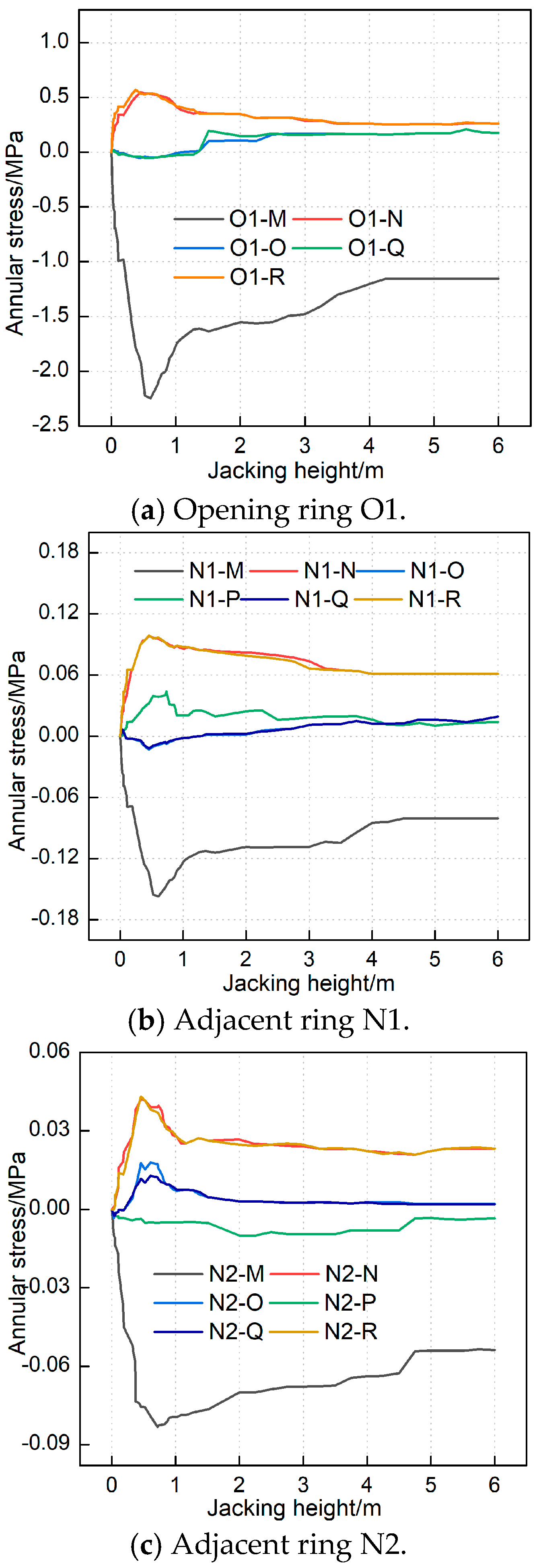
Figure 10 illustrates the stress variations experienced by the segments at distinct construction stages, where positive values denote tensile stress and negative values indicate compressive stress. Throughout the vertical jacking process, both the opening ring and the adjacent ring demonstrated comparable circumferential stress distribution patterns. This similarity indicates that the vault region is subjected to tensile forces while the inner bottom side experiences compressive forces due to jacking. Notably, the compressive stress exhibited an initial increase followed by a subsequent decrease.
The upper section of the arch waist undergoes initial compression followed by tension, while the lower section experiences tensile stress. This tensile stress exhibits an initial increase followed by a subsequent decrease. This phenomenon is attributed to the jacking reaction force, which, during the initial jacking phase, displaces the top cover outward. Consequently, the opening ring segment O1 and the adjacent ring segment N1 are subjected to increased overburden soil pressure, inducing subsidence in the upper portion of the segment and resulting in tension on its inner side. Specifically, point P undergoes tension, causing the arch waist to converge and inducing tension on its inner surface. As overburden pressure diminishes throughout the jacking process, the waist expands outward, leading to a compaction tendency on its inner side.
The maximum tensile and compressive stresses of the segments are presented in
Table 2. Vertical jacking alters the stress distribution within the soil layer, subsequently inducing redistribution of stress disturbances within the segment. This phenomenon primarily affects the opening ring and adjacent ring, while stress disturbances in segments beyond the adjacent ring remain minimal. The maximum tensile and compressive stresses, occurring at the opening ring under jacking force application, are 0.57 MPa and 2.24 MPa, respectively. These stress levels are generally low and significantly below the segment’s strength control threshold. During testing, a systematic investigation focused on cracks at the segment bottom and lower waist region, consistent with the structural stress characteristics. Based on observational data and measured stress values, no tensile or compressive damage cracks were observed in the segment structure within the detectable range.
5. Analysis of Segment Reinforcement Measures
To mitigate the impact of jacking force on tunnel structures, three approaches are available: reducing the thrust force, enhancing segment strength, and increasing the foundation’s bearing capacity. For specific projects, the jacking force typically remains constant. Moreover, augmenting segment toughness presents considerable challenges due to technical complexity and substantial costs. However, foundation reinforcement emerges as a more viable solution. To evaluate grouting reinforcement efficacy and determine its appropriate range of reinforcement, engineering numerical analysis is employed to perform modeling.
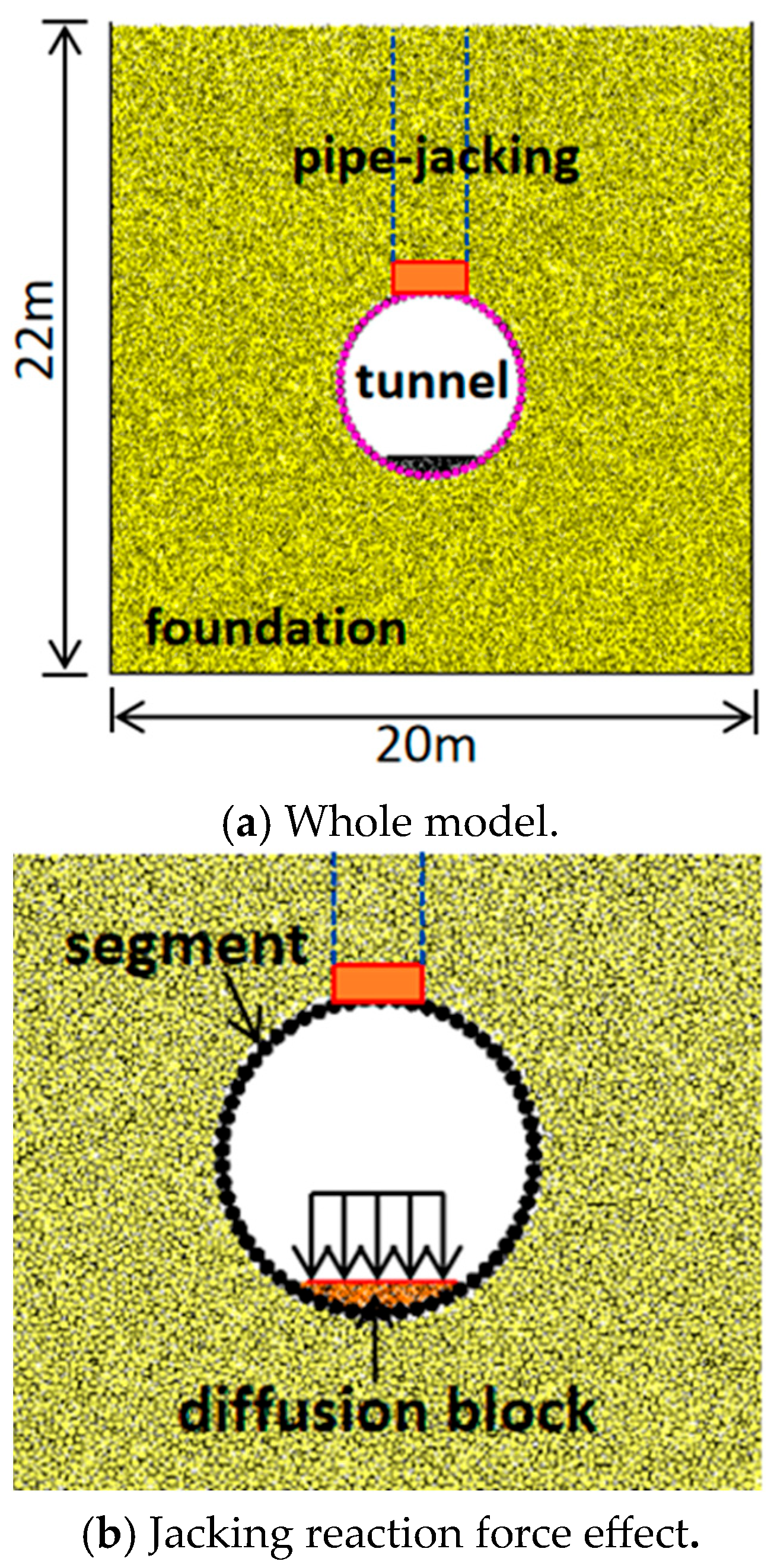
5.1. Particle Flow Calculation Model
The computational domain incorporates boundary effects comprehensively. The model extends 20 m along the X-direction and 22 m along the Y-direction, with the geological formation characterized as a homogeneous clay layer. Within this computational framework, particle interactions are modeled utilizing the contact bond model. The mesoscopic parameters of the clay particles are calibrated via the previously described numerical simulation testing methodology [
19] (
Table 3). Additionally, as established in reference [
20], the ratio of normal to tangential stiffness (
\(k
\)) within the inter-particle contact bonding model is specified as 2.5, while the ratio of normal to tangential bond strength is 1.
In the model container, soil particles are deposited via the gravitational deposition method, achieving equilibrium under the combined action of interparticle contact forces and gravitational forces. To ensure computational validity and operational efficiency, the ratio of the model’s short-side dimension to the average particle diameter must exceed 25. Consequently, particle diameters ranging from 0.05 m to 0.1 m are selected.
Bonded particle assemblies are employed to model the segment, with circular particle units generated at the segment location. The segment exhibits a thickness of 0.3 m, with a corresponding particle diameter of 0.3 m. The elastic modulus is 34.5 GPa and the Poisson’s ratio is 0.2. A rigid wall element represents the thrust pad, which sustains the jacking reaction force. Additional particles are generated at the base of the diffusion block to accurately represent the actual thickness of the reinforced concrete structure.
A parallel bonding contact model governs interactions both between segment units and between the diffusion block and segment. The contact modulus is 34.5 GPa, with a normal-to-shear stiffness ratio (kn/ks) of 1 and a friction coefficient of 0.5.
Based on the model test results, it was observed that segment displacement peaks when the jacking pipe is elevated to approximately h/16. Therefore, the model calculations simulate the jacking process up to h/16—prior to overburden soil failure—while also replicating the jacking excavation procedure. A jacking reaction force of 377 kPa is applied to the diffusion block (
Figure 8c), which subsequently transfers stress to both the shield segment and the foundation.
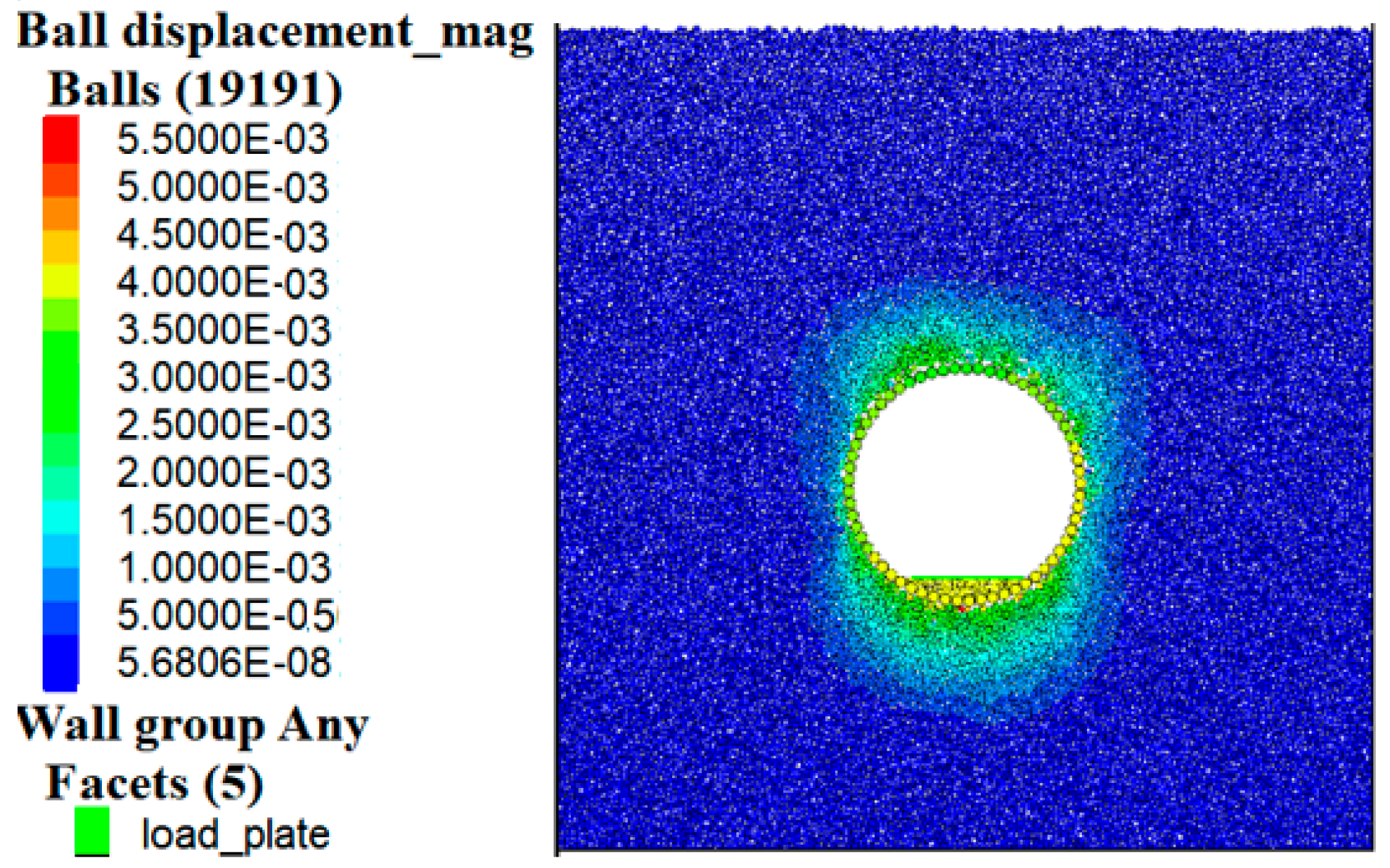
5.2. Model Rationality Verification
Figure 10 depicts the displacement contour plot corresponding to the completion of tunnel construction and the advancement to h/16. As shown in
Figure 10, upon tunnel construction completion, the segment structure manifests significant elliptical deformation, with a maximum settlement of 5.5 mm occurring at the crown. It should be noted that the shield tunnel model test does not simulate the actual excavation process, consequently limiting its capacity to accurately represent displacements occurring at the tunnel invert during the excavation phase.
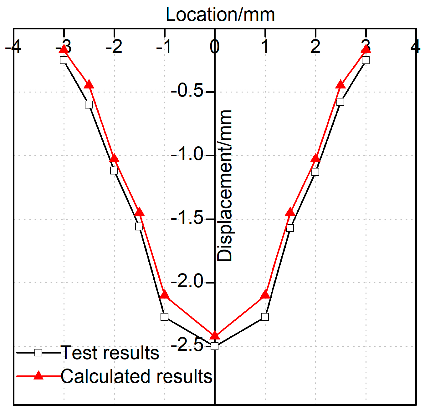
To validate the computational model, the incremental displacement measured at the tunnel invert during the model test is compared with numerical calculation results, as presented in
Figure 11. The data in
Figure 11 demonstrate that the computational results effectively capture the deformation characteristics of the segment structure, exhibiting strong agreement with experimental measurements. The average displacement discrepancy is on the order of 10%, indicating the robustness of the three-dimensional computational model and the reliability of the model test outcomes.
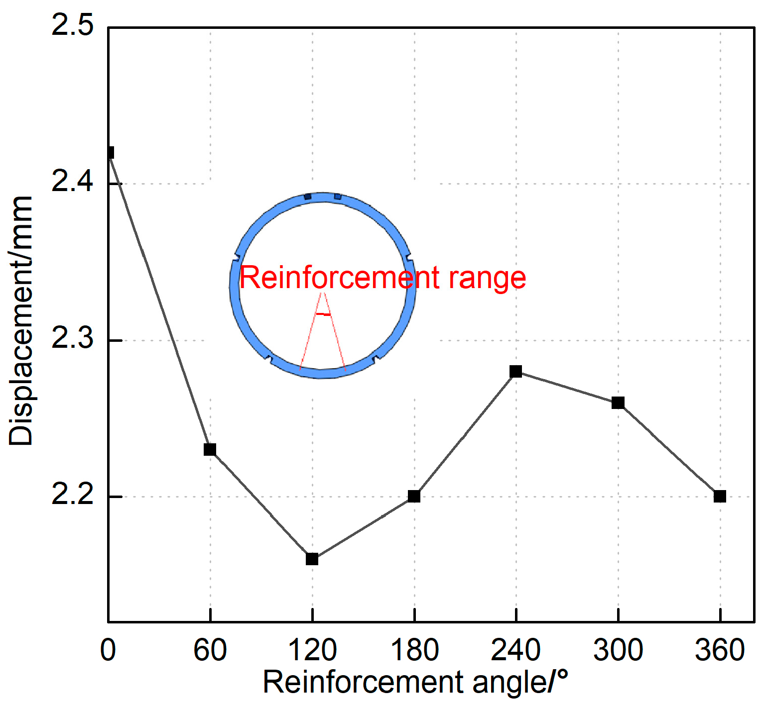
5.3. Analysis of Foundation Grouting Reinforcement
Based on limited prior investigations into foundation reinforcement via pipe jacking force [
4,
21], which proposed grouting reinforcement within angular sectors spanning 120° to 360° exterior to the force-applied segment, this study extends this methodology. Specifically, this research established gradient and full-cycle reinforcement conditions encompassing 30° to 180° beyond the segment under the foundation model’s reaction force. Consistent with Reference [
22], the grouting reinforcement thickness was specified as 1.5 m. The grouted soil layer was assigned the following properties: unit weight γ = 21 kN/m
3, elastic modulus *E* = 1050 MPa, cohesion *c* = 500 kPa, and friction angle φ = 33°. Mesoscopic parameters were derived using the aforementioned calibration methodology.
Figure 12 depicts the maximum segment displacement corresponding to varying reinforcement ranges. The minimal segment displacement, approximately 2.16 mm, occurred with 120° foundation reinforcement. This value closely aligns with the maximum opening displacement of 2.23 mm observed under 60° reinforcement. These findings demonstrate that segment-external grouting reinforcement enhances the soil layer’s capacity to constrain segment deformation, thereby inhibiting the progression of segment displacement and joint dilation. Notably, effective reinforcement beneath the segment was achieved within a significantly narrower 60° range, contrasting with the 120° to 360° range suggested in prior studies. Consequently, meticulous monitoring of grouting reinforcement—specifically regulating grouting pressure to prevent localized segment flotation within allowable tolerances—is critical in practical engineering applications.
6. Conclusions
The vertical jacking model test yielded significant insights into the reaction force distribution pattern and mechanical response of shield tunnels under jacking conditions. A particle flow model was established to evaluate tunnel deformation, with results validated against empirical testing. Furthermore, the efficacy of grouting reinforcement in mitigating tunnel deformation was systematically analyzed, culminating in the formulation of an optimized reinforcement strategy. The principal conclusions are summarized as follows:
- (1)
Jacking Reaction Force Characteristics: The jacking reaction force demonstrates pronounced nonlinear behavior, characterized by rapid pre-failure escalation, substantial post-failure reduction, and subsequent stabilization during advanced jacking stages. This behavioral pattern delineates critical operational phases and informs the optimization of jacking parameters to minimize structural impacts.
- (2)
Tunnel Deformation Response: Jacking forces induce longitudinal bending and segment opening in the tunnel structure, with maximum displacement manifesting between opening segment rings. Abrupt longitudinal load transitions cause maximum dislocation at the interface between the opening and adjacent rings. Deformation attenuation occurs principally along the longitudinal axis, predominantly affecting the opening ring and its immediate neighbor. These deformation mechanisms are critical for enhancing predictive accuracy and maintaining structural integrity during jacking operations.
- (3)
Segment Stress Distribution: Jacking forces redistribute internal stresses within segments. The vault experiences tensile stresses while the invert sustains compressive stresses, both exhibiting initial stress escalation followed by reduction. The upper haunch transitions from compression to tension, whereas the lower haunch remains under tension. Crucially, the structure maintains low stress levels without evidence of tensile or compressive failure, demonstrating adequate resilience to withstand jacking-induced stress variations.
- (4)
Grouting Reinforcement Efficacy: External segment grouting effectively mitigates jacking-induced deformation. An optimal reinforcement angle of 60° at the segment base is established. Notably, conventional practice employs broader reinforcement ranges than necessary, potentially increasing material consumption and construction risks. Restricting the reinforcement zone enhances construction efficiency while maintaining structural performance, thereby optimizing resource utilization and enhancing both economic efficiency and structural safety.
- (5)
Engineering Practice Implications: This research provides a scientific foundation for developing reinforcement strategies and engineering protocols for vertically jacked shield tunnels. The identified optimal reinforcement angle and stress distribution patterns directly inform segment design and construction methodologies, reducing deformation risks and ensuring long-term stability. Moreover, understanding reaction force nonlinearity enables precise control of jacking parameters, effectively mitigating soil failure and structural damage risks.
Author Contributions
Conceptualization, M.H.; methodology, C.Y.; software, C.Y.; validation, Y.Z.; formal analysis, M.H.; investigation, C.Y.; resources, Z.Z.; data curation, M.H.; writing—original draft preparation, M.H.; writing—review and editing, Z.Z.; visualization, J.Y.; supervision, J.Y.; project administration, M.H.; funding acquisition, M.H. and Y.Z. All authors have read and agreed to the published version of the manuscript.
Funding
This research was funded by Guangdong Province Ordinary Universities Characteristic Innovation Projects 2023, grant number 2023KTSCX261, and 2023 Guangdong Province General University Key Research Project (Key Field Special Project) titled “Design and Dynamic Performance Research of a Lightweight Ultra High Strength Concrete (UHSLC)” (Project No. 2023ZDZX3064).
Data Availability Statement
Data are contained within the article.
Conflicts of Interest
Author Chunshan Yang is employed by the Guangzhou General Municipal Engineering Design & Research Institute Co., Ltd. Author Jiayi Yang is employed by the Guangdong Communication Planning & Design Institute Group Co., Ltd. The remaining authors declare that the research was conducted in the absence of any commercial or financial relationships that could be construed as a potential conflict of interest.
References
- Wei, X.; Zhang, S.; Wang, X. Research on jacking force during vertical jacking construction. Chin. J. Rock Mech. Eng. 2023, 42, 3589–3597, (In Chinese with English Abstract). [Google Scholar]
- Wei, X.; Zhang, S.; Wang, X.; Lu, L.; Ding, Z. Study of the indoor model test and CEL simulation of jacking force in the vertical tunnelling method. Adv. Civ. Eng. 2022, 2022, 1–11. [Google Scholar] [CrossRef]
- Wang, L.; Sun, L.; Wang, Z. Field monitoring of a subsea shield tunnel during standpipe lifting. Undergr. Space Technol. Inc. Trenchless Technol. Res. 2015, 45, 52–62. [Google Scholar] [CrossRef]
- Sha, J.Q. Research and Construction Control Points of Vertical Jacking Technology for Water Diversion Tunnel. China Water Wastewater 2016, 32, 118–122, (In Chinese with English Abstract). [Google Scholar]
- Xu, S.; Liu, S.; Chen, J. Tunnel Deformation in Vertical Jacking Construction Stage of Shield Shaft. Henan Sci. 2021, 39, 76–83, (In Chinese with English Abstract). [Google Scholar]
- Yang, C.S.; He, N.; Liu, L.Y. Particle flow simulation of failure mode of overburden soil layer in vertical jacking construction. Highway 2020, 65, 356–360, (In Chinese with English Abstract). [Google Scholar]
- Wei, L.X.; Yang, C.S.; Mo, H.H.; Chen, J.S.; Xu, S.Y. Model tests and discrete element analysis on jacking force of shield shaft vertical pipe jacking. J. Cent. South Uni. Sci. Technol. 2021, 52, 3595–3604, (In Chinese with English Abstract). [Google Scholar]
- Yan, Z.H.; Zhou, F.M.; Wei, X.J. Review and prospects on standpipe lifting method in shield tunnels. Mod. Tunnel. Tech. 2018, 55 (Suppl. S2), 108–120, (In Chinese with English Abstract). [Google Scholar]
- Wei, G.; Hao, W.; Wei, X.J.; Wang, X. Indoor model tests on the construction of vertical pipe jacking in shield tunnel. Chin. J. Geo. Eng. 2022, 44, 62–71, (In Chinese with English Abstract). [Google Scholar]
- Gou, Y.X.; Huang, Q.B.; Yang, X.Q. Model test on deformation and failure mechanism of shield tunnel intersecting ground fissure with large angle. China Civ. Eng. J. 2022, 55, 117–130, (In Chinese with English Abstract). [Google Scholar]
- Lu, X.Y.; Feng, K.; Qi, M.L.; Guo, W.Q.; He, C.; Xiao, M.Q.; Wang, J.Y. Study on longitudinal bending deformation behavior of shield tunnel segments regarding the action of longitudinal forces. Eng. Mech. 2023, 40, 205–216, (In Chinese with English Abstract). [Google Scholar]
- Zhou, Y.H.; Shi, Y.F.; Zhong, G. Experimental study on the force characteristics of shield tube sheets considering the influence of annular joints. J. Rail. Sci. Eng. 2022, 19, 3758–3767, (In Chinese with English Abstract). [Google Scholar]
- Yang, C.S.; Wei, L.X.; Mo, H.H. Longitudinal rigidity of shield tunnel considering deformation characteristic and joints characteristic of lining. J. Zhejiang Univ. 2018, 52, 356–366, (In Chinese with English Abstract). [Google Scholar]
- Wei, L.X.; Yang, C.S.; Chen, W.J. Numerical analysis of ground surcharge effects on deformation characteristics in shield tunnel linings. Appl. Sci. 2024, 14, 2328. [Google Scholar] [CrossRef]
- Ma, L.X.; Xue, C.X.; Yang, H. Longitudinal analysis model for segment lining uplift during shield tunnelling considering shearing dislocation of circumferential joints. Appl. Math. Model. 2024, 132, 298–318. [Google Scholar] [CrossRef]
- Li, H.Y.; Li, X.G.; Yang, Y. Analytical solution for the longitudinal response of cross-fault shield tunnel considering plastic deformation of circumferential joints. J. Cent. South Univ. 2023, 30, 1675–1694. [Google Scholar] [CrossRef]
- Zhou, Z.J.; Fan, Y.X.; Fang, R. Analysis of composite structure of shield tunnel caused by foundation settlement. J. Zhejiang Univ. (Eng. Ed.) 2023, 57, 2476–2488, (In Chinese with English Abstract). [Google Scholar]
- Zhang, J.H.; Li, Y.; Liu, X.W. Statistical analysis of shield tunnel disease based on horizontal convergence in soft clay. China Civ. Eng. J. 2020, 53, 124–130, (In Chinese with English Abstract). [Google Scholar]
- Zhan, Y.X.; Yao, H.L.; Zhang, J.B. Research on the relationship between mesoscopic and marcoscopic mechanical parameters of cohesive coarse grained soil. J. Rail. Eng. Soc. 2016, 33, 12–16, (In Chinese with English Abstract). [Google Scholar]
- Zhao, G.Y.; Dai, B.; Ma, C. Study of effects of microparameters on macroproperties for parallel bonded model. Chin. J. Rock Mech. Eng. 2012, 31, 1491–1498, (In Chinese with English Abstract). [Google Scholar]
- Liu, J.; He, M.D.; Song, H.Y. Mechanical Behaviors of Shield Tunnel Segments Due to Construction of Connecting Passages. J. Geo. Eng. 2013, 35, 271–275, (In Chinese with English Abstract). [Google Scholar]
- Yang, C.S.; Mo, H.H.; Wei, L.X. Deformation response and control of tunnel under the vertical jacking action of shield shaft. J. Rail. Eng. Soc. 2023, 40, 57–63, (In Chinese with English Abstract). [Google Scholar]
| Disclaimer/Publisher’s Note: The statements, opinions and data contained in all publications are solely those of the individual author(s) and contributor(s) and not of MDPI and/or the editor(s). MDPI and/or the editor(s) disclaim responsibility for any injury to people or property resulting from any ideas, methods, instructions or products referred to in the content. |
© 2025 by the authors. Licensee MDPI, Basel, Switzerland. This article is an open access article distributed under the terms and conditions of the Creative Commons Attribution (CC BY) license (https://creativecommons.org/licenses/by/4.0/).


