
Cracking Process of Early-Age Concretes: Basis of Numerical Probabilistic Models


Abstract
1. Introduction
2. Static Cracking Models
3. Probabilistic Cracking Models
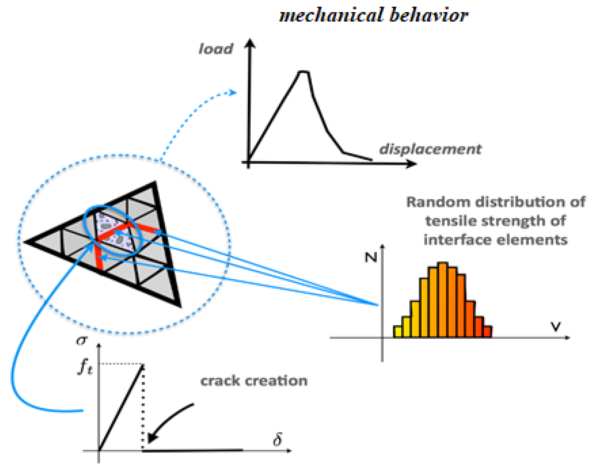
3.1. PEC Model
- Material heterogeneity: concrete is modeled as a heterogeneous material, with its local mechanical properties randomly distributed.
- Scale dependency: these mechanical properties vary depending on the volume of material considered, reflecting scale effects [13].
- Each volume element in the finite element mesh represents a segment of heterogeneous material.
- The tensile strength is randomly assigned to each element, capturing the probabilistic nature of local failure [3].
- Shear strength is defined deterministically as fc/2, where fc denotes the compressive strength of the concrete.
- Cracking is modeled using nonlinear interface elements (quadratic), with failure governed by
- ○
- The Rankine criterion for tension;
- ○
- The Tresca criterion for shear.
- When either criterion is satisfied, the corresponding interface element is considered to have failed. This simulates crack initiation by setting the element’s tensile and shear strength, as well as its normal and tangential stiffness, to zero.
- The randomly assigned tensile strength of a contact interface depends on the volumes of the two adjacent finite elements it connects.
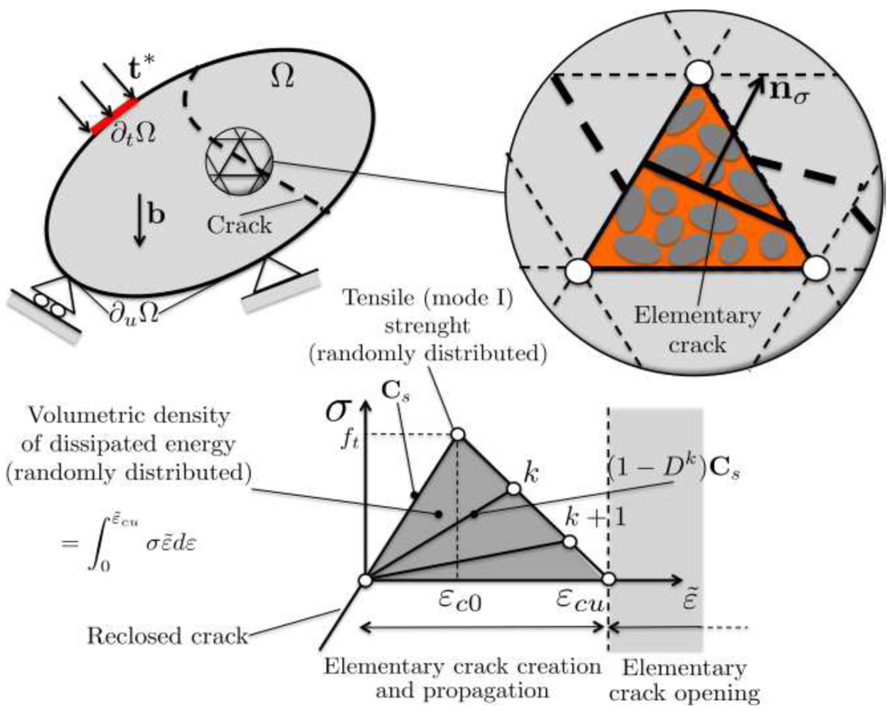
3.2. PSEC Model
- Macrocrack initiation: controlled by the uniaxial tensile strength, ft;
- Macrocrack propagation: governed by the mode I critical fracture energy GIC, as defined by the principles of Linear Elastic Fracture Mechanics (LEFMs).
3.3. Determination of the Values of the Mechanical Parameters of the PEC and PSEC Models
4. Early-Age Cracking
- The mean values of compressive strength, Young’s modulus, and flexural tensile strength increase with the degree of hydration.
- The coefficients of variation of both the compressive strength and flexural tensile strength decrease significantly with increasing hydration, while the reduction is less pronounced for Young’s modulus.
- The mean value of the uniaxial tensile strength, μ(ft), increases with both the degree of hydration and the compressive strength of the concrete.
- The coefficient of variation of the uniaxial tensile strength, σ/μ(ft), decreases with increasing degree of hydration and compressive strength.
4.1. PEC Model
- First Time Sub-Increment (t1)
- Compute the compressive strength of concrete based on its degree of hydration at time t1.
- Calculate the mean tensile strength ftm(t1) using relations (2) and (3), corresponding to the hydration degree at t1.
- Determine the difference ftm1 = ftm(tT) − ftm(t1)), where ftm(tT) is the final mean tensile strength at full hydration.
- Update the tensile strength for each interface element: ft1 = fti − ftm1.
- This update increases the coefficient of variation of the tensile strength compared to its initial value, consistent with the experimental findings previously discussed.
- For each interface element, evaluate (σt1 − ft1). If σt1 − ft1 ≥ 0, the element opens, indicating crack formation.
- Second Time Sub-Increment (t2)
- Calculate the compressive strength of concrete corresponding to its hydration state at t1 + t2.
- Determine the mean tensile strength ftm(t1 + t2) for this hydration state.
- Compute the difference ftm2 = (ftm(tT) − ftm(t1 + t2)).
- Update the tensile strength for each interface element: ft2 = fti − ftm2.
- Evaluate the normal tensile stress σt2 at the centroid of each interface element.
- For each interface element, check whether σt2 ≥ ft2; if so, the element opens and cracks propagate.
- Final Time Sub-Increment (tn)
- At this stage, the simulation time reaches its final value: (t1 + t2 +…+tn) = tT.
- Each interface element now regains its initial tensile strength fti, assigned at the beginning of the simulation.
- Compute the normal tensile stress σtn the centroid of each element.
- For each element, evaluate (σtn − fti). If σtn − fti ≥ 0, the element opens and cracks are formed.
4.2. PSEC Model
- First Time Sub-Increment, t1:
- Compute the compressive strength based on the degree of hydration of the concrete at time t1.
- Calculate the mean tensile strength, ftm(t1), using relations (2) and (3), and the mean fracture energy, GICm(t1), using relation (6), both based on the degree of hydration.
- Determine the differences ftm1 = (ftm(tT) − ftm(t1)) and GICm1 = (GICm(tT) − GICm(t1)), where (tT) is the time corresponding to complete hydration.
- Update the tensile strength and fracture energy assigned to each volume element: ft1= fti − ftm1, GIC1= GICi − GICm1.
- Compute the maximum principal tensile stress, σt1, at the centroid of each volume element using the thermo-chemo-mechanical model.
- Evaluate σt1 − ft1 for each volume element:
- ○
- If σt1 − ft1 < 0, the element remains in the linear elastic regime.
- ○
- If σt1 − ft1 ≥ 0, the element enters the non-linear regime, and a damage parameter D = D1 (specific to each element) is assigned at the end of t1t.
- ○
- If the energy GIC1 is fully dissipated during t1, the element is considered fully damaged (see Section 3.2).
- Second Time Sub-Increment, t2:
- Recalculate the compressive strength based on the degree of hydration at t1 + t2.
- Compute the updated mean tensile strength, ftm(t1 + t2), and mean fracture energy, GICm(t1 + t2).
- Determine the new differences: ftm2 = ftm(tT) − ftm(t1 + t2), GICm2 = GICm(tT) − GICm(t1 + t2).
- Update the tensile strength and fracture energy values: ft2 = fti − ftm2, GIC2 = GICi − GICm2.
- Calculate the maximum principal tensile stress, σt2, at the centroid of each volume element:
- ○
- For elements still in the linear-elastic regime, use the stiffness matrix based on the degree of hydration (thermo-chemo-mechanical model).
- ○
- For previously damaged elements, use the same stiffness matrix but multiplied by D1 (this approach ignores self-healing effects in early-age concrete).
- Evaluate σt2 − ft2 for each element:
- ○
- If σt2 − ft2 < 0, the element remains linearly elastic.
- ○
- If σt2 − ft2 ≥ 0, the element either enters the non-linear regime or continues accumulating damage. The damage parameter becomes D2, specific to each element.
- ○
- If GIC2 is entirely dissipated during t2, the element is fully damaged.
- Final Sub-Increment, tn:
- The simulation concludes at tT = t1 + t2 + ⋯ + tn.
- Each undamaged volume element retains its initial values fti and GIci.
- The calculation procedure at this stage follows the same steps described for the second sub-increment t2.
5. Conclusions
Funding
Data Availability Statement
Conflicts of Interest
References
- Fairbairn, E.M.R.; Azenha, M. Thermal Cracking of Massive Concrete Structures. In RILEM State-of-the-Art Reports; Fairbairn, E.M.R., Azenha, M., Eds.; Springer International Publishing: Cham, Switzerland, 2019; Volume 27, ISBN 978-3-319-76616-4. [Google Scholar]
- Rossi, P. Numerical Designing of Fiber Reinforced Concrete Eco-Constructions. Materials 2023, 16, 2576. [Google Scholar] [CrossRef] [PubMed]
- Rossi, P.; Wu, X. Probabilistic model for material behavior analysis and appraisement of concrete structures. Mag. Concr. Res. 1992, 44, 271–280. [Google Scholar] [CrossRef]
- Rita, M.; Rossi, P.; Fairbairn, E.; Ribeiro, F. Determination of the Probabilistic Properties of the Critical Fracture Energy of Concrete Integrating Scale Effect Aspects. Appl. Sci. 2024, 14, 462. [Google Scholar] [CrossRef]
- Rita, M.; Rossi, P.; Fairbairn, E.; Ribeiro, F.; Tailhan, J.-L.; Andrade, H.; Mota, M. Parallelization Strategy for 3D Probabilistic Numerical Cracking Model Applied to Large Concrete Structures. Buildings 2024, 14, 2327. [Google Scholar] [CrossRef]
- Mazars, J. Application de la Mécanique de L’endommagement au Comportement non Linéaire et a la Rupture du Béton Structure. Ph.D. Thesis, Ecole Normale Supérieure de l’Enseignement Technique, Cachan, France, 1984. (In French). [Google Scholar]
- Pijaudier-Cabot, G.; Bažant, Z. Non-local damage theory. J. Eng. Mech. 1987, 113, 1512–1533. [Google Scholar] [CrossRef]
- Desmorat, F.; Gatuingt, F.; Ragueneau, F. Anisotropic damage model and related computational aspects for quasi-brittle materials. Eng. Fract. Mech. 2007, 74, 1539–1560. [Google Scholar] [CrossRef]
- De Borst, R.; Nauta, P. Non-orthogonal cracks in a smeared finite element model. Eng. Comput. 1985, 2, 35–46. [Google Scholar] [CrossRef]
- Hillerborg, A.; Modeer, M.; Petersson, P. Analysis of crack formation and crack growth in concrete by means of fracture mechanics and finite elements. Cem. Concr. Res. 1976, 6, 773–782. [Google Scholar] [CrossRef]
- Hillerborg, A. Numerical methods to simulate softening and fracture of concrete. In Fracture Mechanics of Concrete: Structural Application and Numerical Calculation; Springer: Dordrecht, The Netherlands, 1985; pp. 141–170. [Google Scholar]
- Chang, Z.; Zhang, H.; Schlangen, E.; Šavija, B. Lattice Fracture Model for Concrete Fracture Revisited: Calibration and Validation. Appl. Sci. 2020, 10, 4822. [Google Scholar] [CrossRef]
- Rossi, P.; Wu, X.; Le Maou, F.; Belloc, A. Scale effect on concrete in tension. Mater. Struct. 1994, 27, 437–444. [Google Scholar] [CrossRef]
- Rossi, P. Determination of Toughness Characteristics of Concretes. Curr. Trends Civ. Struct. Eng. 2023, 10, 1–7. [Google Scholar]
- Moita, G.C.; Fairbairn, E.M.R.; Toledo Filho, R.D.; Rossi, P. Experimental Investigation into the Evolution of Probabilistic Characteristics of Early-Age Concrete. Buildings 2024, 14, 668. [Google Scholar] [CrossRef]
- Ulm, F.-J.; Coussy, O. Modeling of Thermo-Chemo-Mechanical Couplings of Concrete at Early Ages. J. Eng. Mech. 1995, 121, 785–794. [Google Scholar] [CrossRef]
- Silvoso, M.M. Optimization of the Construction Phase of Concrete Structures vis-a-vis the Hydration Effects Using Genetic Algorithms. Ph.D. Thesis, COPPE/UFRJ-PEC, Rio de Janeiro, Brazil, 2003. [Google Scholar]
- Ferreira, I.A. Parallel Solution of a Thermo-Chemo-Mechanical Model for Early-Age Concrete. Ph.D. Thesis, COPPE/UFRJ-PEC, Rio de Janeiro, Brazil, 2008. [Google Scholar]
- Ribeiro, L.F.B.; Ferreira, I.A. Parallel Implementation of the Finite Element Method Using Compressed Data Structures. Comput. Mech. 2007, 41, 31–48. [Google Scholar] [CrossRef]
- Fairbairn, E.M.R.; Silvoso, M.M.; Koenders, E.A.B.; Ribeiro, F.L.B.; Toledo Filho, R.D. Thermo-Chemo-Mechanical Cracking Assessment for Early-Age Mass Concrete Structures. ACI Concrete International 2012, 34, 30–35. [Google Scholar]
- Ulm, F.-J.; Coussy, O. Strength Growth as Chemo-Plastic Hardening in Early Age Concrete. J. Eng. Mech. 1996, 122, 1123–1132. [Google Scholar] [CrossRef]
Disclaimer/Publisher’s Note: The statements, opinions and data contained in all publications are solely those of the individual author(s) and contributor(s) and not of MDPI and/or the editor(s). MDPI and/or the editor(s) disclaim responsibility for any injury to people or property resulting from any ideas, methods, instructions or products referred to in the content. |
© 2025 by the author. Licensee MDPI, Basel, Switzerland. This article is an open access article distributed under the terms and conditions of the Creative Commons Attribution (CC BY) license (https://creativecommons.org/licenses/by/4.0/).
Share and Cite
Rossi, P. Cracking Process of Early-Age Concretes: Basis of Numerical Probabilistic Models. Buildings 2025, 15, 2259. https://doi.org/10.3390/buildings15132259
Rossi P. Cracking Process of Early-Age Concretes: Basis of Numerical Probabilistic Models. Buildings. 2025; 15(13):2259. https://doi.org/10.3390/buildings15132259
Chicago/Turabian StyleRossi, Pierre. 2025. "Cracking Process of Early-Age Concretes: Basis of Numerical Probabilistic Models" Buildings 15, no. 13: 2259. https://doi.org/10.3390/buildings15132259
APA StyleRossi, P. (2025). Cracking Process of Early-Age Concretes: Basis of Numerical Probabilistic Models. Buildings, 15(13), 2259. https://doi.org/10.3390/buildings15132259