1. Introduction
Additive manufacturing (AM) involves constructing objects directly from three-dimensional digital models by adding material layer upon layer, contrasting with traditional subtractive manufacturing methods [
1].
As a key innovation of the Industry 4.0 era, AM holds significant promise for revolutionising manufacturing practices. Its potential to fundamentally alter conventional paradigms supports the ongoing shift towards the conceptualisation, design, and adoption of sustainable and circular business models [
2], which are increasingly regarded as essential for future industrial development. These faster and more automated processes, which are already used in medicine, automotive or aerospace engineering, are promising for civil engineering, where construction times and costs are expected to be reduced.
3D concrete printing, as a form of additive manufacturing, is a new construction process for building concrete components by depositing a cemented mixture layer by layer [
3,
4]. However, unlike applications in other areas, civil structures are large-scale constructions, with lengths, heights, or spans of tens of metres, which are subjected to complex stresses such as gravity, overload, wind, earthquakes, etc.
This technology is directly linked to the principles of the circular economy (CE). This concept refers to ‘an economic system that is based on business models which replace the “end-of-life” concept’ [
5]. Its core principles, known as the 3Rs —“reduce, reuse, recycle”— are fully aligned with fostering economic growth while safeguarding the environment. This approach promotes extending the lifespan of products that have exhausted their physical or functional utility and would otherwise be discarded, thereby maximising their utilisation and preserving their value for as long as possible [
6]. It supports reuse and recycling efforts [
7] by incorporating recycled materials as inputs in the production process. Additionally, it contributes to reduction, since in situ fabrication allows for optimisation of raw material and water consumption by producing only the material needed. A study conducted by Delft University of Technology [
8] indicated that 3D concrete printing can reduce material waste by up to 90%. An important added benefit of this method is its capacity to enable construction without the need for formwork.
Major steps in the 3D concrete printing process are described in [
9]. First, the build material is transported to the printhead. Next, the printhead extrudes the material, depositing it in the desired shape. During deposition, the material may deform due to its own weight and the forces generated by the process. As additional layers are added, they are placed on top of each other, which can also cause deformations resulting from the weight of the upper layers and other factors such as early-age shrinkage, initial creep, and thermal expansion. Each one influences the final shape and quality of the structure. According to [
10], future research should concentrate on specific areas, including the investigation of the relationship between defects, microstructure, and the performance of produced elements. This area has received limited attention within the construction industry, particularly regarding its effects on prefabrication, on-site assembly, and large-scale projects.
As a consequence of printing process, printable materials must meet requirements in terms of strength (as they are structural materials), workability (must be pumpable and extrudable through a nozzle), and buildability (must have a consistency that allows it to maintain the shape of the extruded layers and support the weight of the layers that are deposited afterwards without deforming significantly). It is important to note that bonding surfaces between layers can represent a weakness that significantly affects the structural strength of the material. In this sense, in [
11] stated, using the discrete element method (DEM), that the flexural strength of the printed components is lower than the flexural strength of concrete with no layers. Models showed that the maximum load in the numerical models of 3D-printed concrete varies between 79.7% and 84.2% of the maximum load in the model with no layers. In other words, control over curing times must be very precise, allowing stacking, but avoiding the formation of cold joints.
Moreover, due to the nature of the printing systems themselves, in which extrusion takes place via a screw-type pump, the materials used are not concrete. As such, since the coarser particle size fraction is not represented in order to avoid problems of segregation, clogging and damage can occur to the mechanics. These materials are rather mortars, with direct repercussions on the higher water content required in the mix, which penalises stackability and long-term strength. Therefore, obtaining a uniaxial compressive strength of more than 25 MPa, which is required to replace structural concrete, is not always easy to obtain and requires multiple tests, adjustments, and, in many cases, additives that make the material more expensive. In this sense, ref. [
12] found that the environmental impact caused by 3D printing concrete construction is generally larger than traditional ones because additional cement is required in the 3D printing process to maintain dependable concrete performance.
In this complex context, the introduction of a new variable, such as the use of recycled aggregates, represents a new challenge. Research on recycled coarse aggregate in concrete is extensive, but studies on recycled sand in mortar are limited due to its low density and high water absorption, which can impair workability and strength [
13,
14,
15,
16,
17,
18,
19], critical for 3D printing. Evangelista and Brito [
16] recommend a maximum replacement of 30%. However, recycled sand may be viable in 3D-printed concrete with proper mix optimisation [
20,
21,
22]. Ref. [
21] used different proportions of recycled sand (between 12.5% and 50%), reporting a reduction in strength as the amount of recycled aggregate is increased.
The utilisation of alternative recycled materials such as glass, geopolymer, fly ash, and alkali-activated slag or fiber from plants has also been explored [
23,
24,
25,
26,
27]. One emerging alternative that is gaining recognition is the reuse of mining waste. In [
28], a study was conducted on the use of ceramic waste powder in concrete beams, concluding that contents above 10% of such materials negatively affect strength. However, when the proportion is below 10%, the use of these recycled materials is suggested and recognised as both a cost-effective and environmentally friendly approach. Another interesting work [
29] examined the effects of waste andesite dust on the flexural behavior of reinforced concrete beams by means of experimental testing and 3D finite-element modeling. They concluded that using up 10% reduction of replacement strength and ductility capacities is not hard and this is a reasonable choice to obtain eco-friendly concrete. Other experimental studies, such as [
30,
31], have explored the use of marble tailings or ceramic waste again within concrete mixtures.
Additionally, [
32] demonstrated the feasibility of using mining tailings derived from mineral flotation processes in printable mortars. Mining tailings generated during the treatment and concentration of ores are classified as solid mineral residues with a reduced grain size, ranging from silt (4 µm to 62 µm) to sand (62 µm to 4 mm). These tailings are produced, transported, and deposited in the form of sludge across damn structures. If not properly managed, mining tailings can cause irreversible environmental damage and pose risks to human health.
There are more than 20,000 mine tailings dams around the world [
33]. The failure of these structures ranks among the most damaging types of instability phenomena, both in terms of human casualties and environmental consequences. Along XX century, over 130 incidents have been recorded, resulting in nearly 2800 deaths and causing substantial environmental damage. Since the frequency of mine tailings dam failures has generally declined over time, the occurrence of major failures with severe consequences has risen. Some of the most recent cases include the failure of the Brumadinho dam (Brazil, 2019), which resulted in 270 fatalities; the Fundão dam failure (Brazil, 2015), which caused 19 fatalities; or the Slava dam failure (Italy, 1985), which led to 269 fatalities.
As [
34] stated, the long-term consequences of tailings dam failures remain poorly understood and insufficiently researched. Should hazardous substances infiltrate groundwater systems; the resulting chemical, environmental, and social effects would likely be irreversible. The cumulative effects of tailings releases are linked to the accumulation of harmful substances in sediments and toxic metals into ecosystems over extended periods and represents one of the most serious long-term threats associated with tailings dam failures.
Apart from the risk of failure, with the human, material and environmental damage that this entails, these deposits pose several challenges, particularly after mining operations have ended [
32]. Issues include land use, ensuring impermeability to prevent contaminant leakage, managing seismic risks, erosion, piping, or overflows. Addressing these factors is essential to reduce the likelihood of large-scale contaminant release.
Therefore, the possible reuse of these kinds of materials offers a dual advantage from an environmental perspective, making it a subject of particular interest. However, given the diversity of materials in terms of particle size distribution and composition, the potential for utilising these residues must be assessed on a case-by-case basis.
Therefore, important issues must be addressed prior to extending this type of solution to civil engineering applications. This work considers some of these issues, which affect three different phases of a structure’s lifecycle: design, construction, and utilisation.
The first, related to the structural design, is to determine whether the presence of bonding surfaces between layers can influence the structural behaviour of the printed element, and how these interfaces will affect the design of the constructed structure. Accordingly, considerations concerning bonding surfaces between layers have been incorporated through 3D discrete element method modelling of various structural elements (such as walls or beams), comparing their behaviour to that of the same material without such interfaces.
The second, related to the construction phase, is to verify whether it is feasible to produce a structural, printable, and stackable mortar made from recycled mining waste. This study aims to demonstrate the viability of reusing a specific type of mining tailings in a mortar suitable for 3D printing, addressing the technical requirements inherent to such materials: from pumpability and buildability to the final mechanical strength as a structural material. Particular effort has been made to demonstrate that a material can be achieved whose deposition does not require interruptions for the curing of the previous layers.
Finally, to date, there is limited experience regarding the behaviour of these materials under extreme loads, especially concerning the interfaces between layers. If these bonding surfaces experience reduced strength, it will affect the overall structural performance. Therefore, an additional significant question addressed in this study is the experimental evaluation of the effects of extreme loadings, such as fire and seismic events, on these printed materials.
2. Materials and Methods
2.1. Characterisation of the Mortar
One of the primary concerns in the field of 3D printing of cementitious materials is the composition of the mortars employed and the various methods of characterisation proposed.
The printable material must meet certain specific requirements regarding strength, since it is a structural material; workability, meaning it should be pumpable and extrudable through a nozzle; and constructability, which means it needs to have a consistency that allows it to maintain the shape of the extruded cords and support the weight of the layers deposited afterward without deforming significantly. Additionally, the interfaces between layers should not become weak points that significantly affect the structural integrity of the material. In other words, precise control of curing times is essential to facilitate stacking and prevent the formation of cold joints.
In this study, a mortar was prepared using commercial sand of siliceous origin, with a granulometry of less than 3 mm. To this aggregate, 12.5% of mining tailings from an abandoned deposit in northern Spain were added. Mineralogically, the tailings are primarily composed of silica (80%), calcite (15%), and feldspars (5%). It is a low potential contaminant material, with traces of Al2O3 (0.9%), Fe2O3 (1.5%), SO3 (2.3%), K2O (0.42%), Na2O (0.04%), and BaO (0.61%).
Because the tailings dam, from which the samples were taken, was constructed by hydraulic dumping, the sedimentation of the transported solids inside the dam occurs with a granulometric segregation. The coarser materials sediment closer to the spill point and the finer ones move away towards the inside of the deposit. For this work, five samples were taken with the help of an excavator along the embankment, about 10 m inland from the dyke. The samples, each weighing 100 kg, were extracted at a depth of about 3 m and, once in the laboratory, were homogenised to provide representative material for tests.
From a granulometric perspective, they were classified as fine sand, as over 99% of the particles were smaller than 0.25 mm, with an average particle size of 0.1 mm. The fines content (silt and clay) was approximately 18%.
The smaller particle size of the aggregate used, including the presence of fine particles, primarily results in increased water demand, which in turn leads to reduced long-term strength of the material. Two strategies can be adopted to counteract this effect. The first, employed in [
32] to achieve strengths exceeding 25 MPa, involves maintaining a low water-to-cement ratio while incorporating a superplasticiser into the mix to preserve workability and pumpability. In the present case, a different approach has been taken: the mix was prepared with the amount of water required to ensure adequate workability and pumpability, but the performance of the cement has been enhanced. It is worth emphasising that the decision was made to improve the type of cement rather than to increase its dosage in order to minimise the environmental footprint as referenced in [
12]. The cement utilised was CEM I 42.5 N Portland cement.
Additionally, the predominantly siliceous nature of the recycled material also contributed to improving strength, enabling results comparable to those in [
32] to be achieved without the use of superplasticisers.
To define the appropriate water/cement ratio, the work of Yi et al. [
35] was employed, relating the settlement experienced by a mortar in the slump test to the diameter it reaches after collapse, as a consequence of the dynamic effect introduced through the slump flow test. This relationship was used to establish a range or “printability window” within which the mortar exhibits an optimal consistency for printing. An example of one of the tests conducted is shown in
Figure 1. In this way, a minimum water/cement ratio of 0.63 was established for the work mortar.
The used mortar had the composition shown in
Table 1. It should be noted that the intention of this study is not to evaluate the behaviour of the mix with different recycled content, as this has already been developed in [
32]. In this study, the recycled content considered optimal from that work has been used as a starting point. Logically, in the case of using other recycled materials, this study should be carried out beforehand.
Another relevant aspect in this type of mixture with recycled materials is the potential risk of leaching. Although the materials used are not potential contaminants, the cement used for the mortar fabrication functions as a stabilisation and solidification (S/S) treatment for the mining tailings.
S/S is an efficient and cost-effective method for soil remediation, used on a variety of contaminated soils. Ordinary Portland cement (OPC) is widely recognised as an effective agent for S/S due to its affordability, broad applicability, and ease of handling. OPC-based matrices can effectively immobilise potentially toxic elements such as heavy metals and polycyclic aromatic hydrocarbons. [
36] refers the use of percentages up 12% to fix chromium, copper, and mercury or 8% to treat material that was contaminated with arsenic, chromium, and polycyclic aromatic hydrocarbons.
In this case, the cement content in the mixture (approximately 25%) indicates that, despite the presence of potential contaminants, the risk of leaching is very limited. However, for another type of mining tailings, a leachability test should be conducted.
In addition to being pumpable, it is necessary for the mortar to demonstrate minimum mechanical properties after setting. Consequently, specimens were prepared for subsequent testing, resulting in an average uniaxial compressive strength of 27.8 MPa (exceeding 25 MPa in all tested specimens) and a tensile strength of 4.6 MPa. However, in order to consider the dispersion in strength, a reduction factor of 1.15 was applied to both uniaxial compressive strength and tensile strength of mortar. So, we accepted as representative values 24 MPa (for uniaxial compression strength) and 4 MPa (for tensile strength).
Another relevant aspect of a printable mortar is its buildability, which is a property that contrasts with pumpability. The strategy employed in this case involves adding an accelerator at the extrusion head to harden the mortar almost immediately upon deposition. As will be discussed in
Section 3, this approach allows for the stacking of as many layers as necessary without the failure caused by the deformation of the lower layers under the weight of subsequent ones. For this work, the MasterRoc 167 SA accelerator from Master Builders Solutions has been selected. It is an alkali-free product that allows the setting to be completed within 5 min (depending on its dosage, in this case 2%).
2.2. Characterisation of the Printed Material
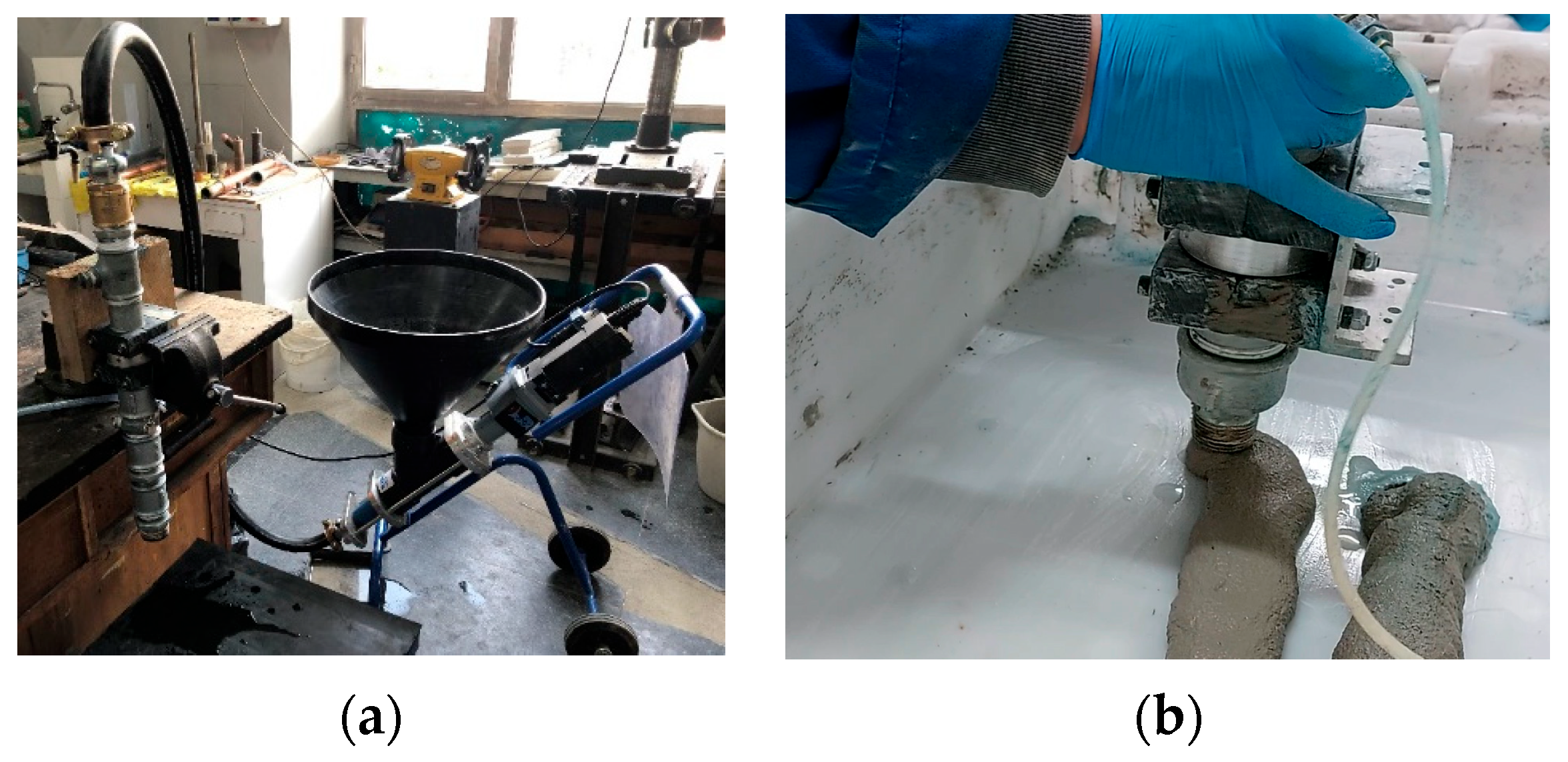
Now, the aim was to verify the homogeneity of the printed materials and to assess the influence of the layered structure and interface properties on their behaviour. To achieve this, mortar extrusion was carried out through a nozzle driven by an injection pump, with layers manually stacked one atop another (see
Figure 2).
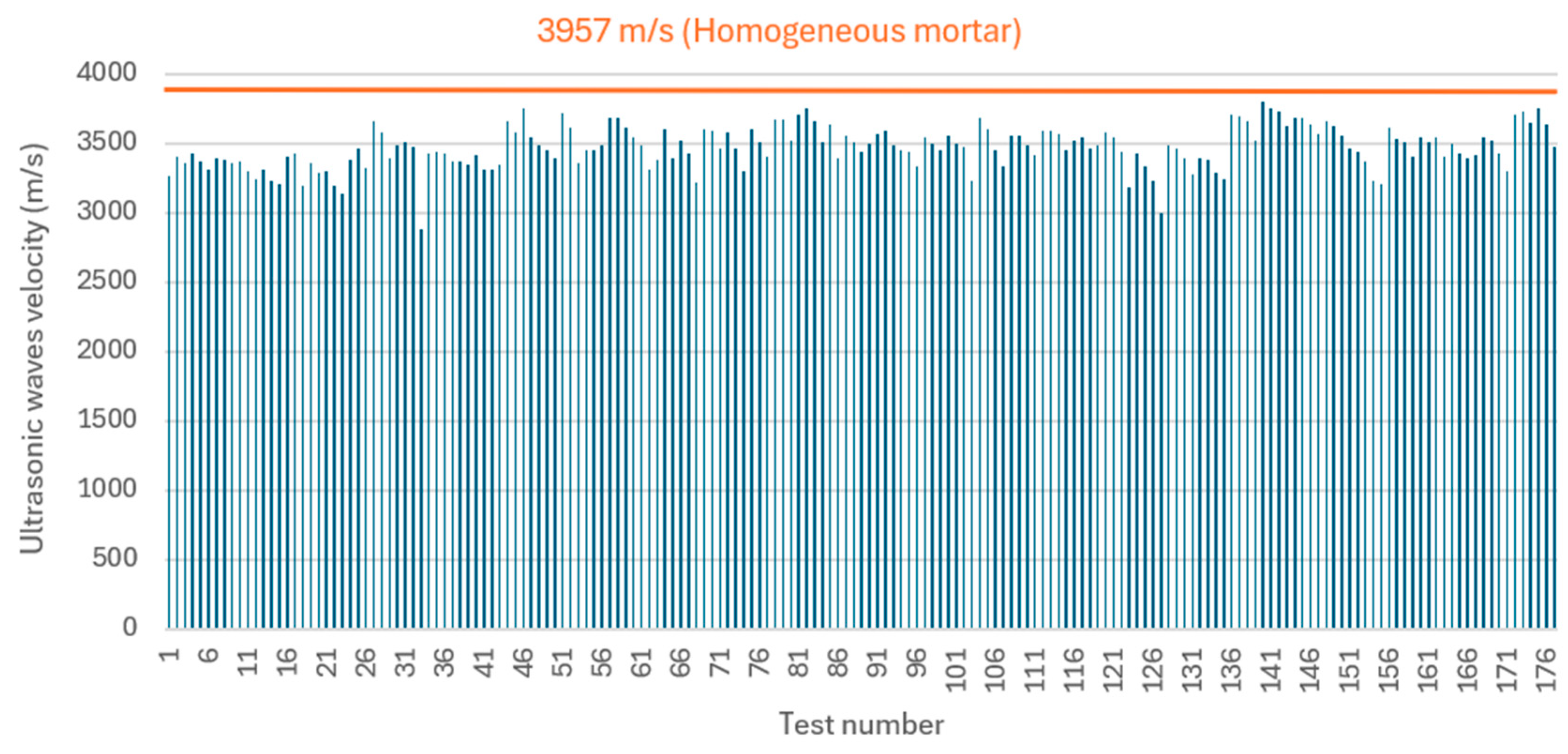
Initially, non-destructive testing methods based on ultrasonic techniques were employed to assess the uniformity of the printed specimens. For this purpose, a reference pattern of the mortar itself was required to enable comparison of the results with the printed elements. Consequently, five cubic specimens measuring 100 × 100 × 100 mm were fabricated, yielding an average ultrasonic velocity of 3957 m/s with a standard deviation of 127 m/s.
Subsequently, forty-five printed specimens, each comprising between two and five layers, were evaluated. Orthotropic measurements were taken along directions parallel and perpendicular to the interfaces between layers (see
Figure 3).
This approach aims to determine whether significant differences exist between the initial layers, which are compacted by the weight of the subsequent layers, and the final ones, as well as to assess whether the interface constitutes a clear discontinuity, potentially due to poor adhesion or cold joints. As can be seen in
Figure 3, the deformations resulting from the stacking of three layers are in the order of 0.5 cm.
The remaining tests were designed to evaluate the strength of the interfaces or joints between layers. For this purpose, two types of tests were conducted: flexural tests and joint opening tests using a chisel. Regarding the flexural tests, they were performed on specimens comprising three and four layers, following the arrangements shown in
Figure 4.
Depending on the failure surface (across the layer or at an interface), the strength obtained will be related to the tensile strength of the homogeneous material or to the adhesion of the joints. As for the chisel tests, these are non-standardised tests that are involved applying an increasing load to the joint via a chisel supported on it, as illustrated in
Figure 4. The maximum load is divided by the generated take-off surface in order to estimate a strength parameter related to the adherence on the contact surface.
2.3. Fire and Dynamic Tests
A series of tests were conducted to evaluate the behaviour of the printed material under fire conditions, aiming to determine whether the presence of interfaces could constitute a weakness in such scenarios. The specimens, which were equipped with internal temperature sensors, were subjected to direct fire loads until their temperature exceeded 250 °C for more than four hours. Subsequently, they were examined using ultrasonic testing, flexural testing, and chisel testing, in order to compare the results with those of specimens printed without fire exposure.
Figure 5 illustrates a fire test followed by a flexural test resulting in fracture through the joint or interface.
Furthermore, the behaviour of the material under dynamic phenomena was analysed by subjecting specimens of printed material (3 and 4 layers) to dynamic loads, in order to subsequently evaluate their resistance performance. Two different vibration amplitudes were selected: the one corresponding to the most adverse situation according to the Spanish seismic code NCSE-02, which is equivalent to 0.24 g, and the one corresponding to the strongest earthquake of category IX according to the Mercalli scale, which is 1.27 g. The duration of the vibration in all cases was 1 min, to include the effect of successive tremors. Dynamic excitation, consisting of a three-component acceleration with the same amplitude, was applied to the lower surface of the specimens.
2.4. Modelling
Numerical calculation software based on finite differences, FLAC3D (version 7.00), from Itasca Consulting Group was utilised to perform two types of modelling:
To evaluate the implications that the presence of potential planes of weakness due to interfaces between stacked layers has on structural design: For this purpose, the behaviour of the printed material with interfaces was modelled and compared to that of the same mortar without such interfaces, which would serve as a behaviour pattern. The comparison was carried out under different structural loadings and is more qualitative than quantitative;
To assess the importance of rheology and hardening of the material in its stackability, in order to understand the implications of this question during the construction process: The simulated model consists of three layers, each 5 cm wide, 5 cm high, and 30 cm in total length, stacked on top of each other. To simulate the joints between layers, interface elements were used between the three modelled layers. These elements allow the simulation of behaviour discontinuities. Once three cords are stacked, the deposition of subsequent layers is simulated by applying progressive overloads equivalent to the weight of the new cords on top of the upper layer.
3. Results and Discussion
This section shows and discusses the results obtained in the different tests and modelling, structured according to their implications in the different steps of the additive manufacturing process addressed in this work, i.e.:
Issues to consider during design;
Issues to consider during layer deposition;
Implications on fire and seismic situations
3.1. Issues to Consider During Design
During structural design, it must be taken into account that the printed material exhibits orthotropic behaviour with the presence of potential planes of weakness. Ultrasonic velocity tests in the longitudinal direction (more than 175 measurements) yielded an average value of 3469 m/s, with a standard deviation of 152 m/s. This represents a 12% reduction compared to the original material. In
Figure 6, all the obtained results are displayed, demonstrating that the printing process allows for a high degree of homogeneity in the layers.
This slight decrease may be attributed to the fact that the mixture has not been optimised for the extrusion process, given that it was prepared using the minimum permissible water/cement ratio for this mortar (0.63). This issue could be rectified by adding a superplasticiser to the mixture, which would obviate the need to increase the water/cement ratio and thereby avoid compromising its strength.
Regarding measurements in the direction perpendicular to the contact surfaces between layers, the average value recorded was 3211 m/s, which is nearly 20% lower than that of the original mortar. Furthermore, it was observed that the standard deviation increased to 540 m/s, indicating a greater dispersion of the results (see
Figure 7).
Taking these results into account, the subsequent simulation models the behaviour of structural elements manufactured from the printed material and subjected to various load types, specifically: compression, compression combined with shear, and flexion. The performance of these elements has been compared with their equivalent counterparts in the same homogeneous mortar.
The homogeneous mortar was simulated using in FLAC3D a Mohr–Coulomb constitutive model. The printed material was modelled employing a ubiquitous joint behaviour model, characterised by the presence of planes of weakness distributed homogeneously within a continuous Mohr–Coulomb framework. These planes can fail under both shear and tensile stresses. In the conducted simulations, the properties of the continuous Mohr–Coulomb material were previously calibrated through a model simulating a simple compression test of the mortar, while the properties of the ubiquitous joints were defined based on results from chisel tests.
3.1.1. Element Subjected to Compressive Loads
The initial comparison was conducted on a specimen measuring 5 cm in width, 100 cm in length, and 200 cm in height, which would simulate a load-bearing wall. A progressively increasing load was applied to the upper face of the specimen, inducing a compressive stress. This load was increased until failure of the wall occurred. To exploit the symmetry of the problem, only a height of 100 cm was simulated, with a boundary condition at the base equivalent to preventing vertical displacements.
Figure 8 presents some representative results of the comparison. Firstly, the vertical stress versus vertical displacement curve is shown, demonstrating that the behaviour is very similar for both types of material, with strengths around 24 MPa. Additionally, the failure state in both cases has been depicted.
The green areas represent elements that have experienced failure at some moment during the process (shear-p if due to shear or tension-p if due to tension), but have reached an equilibrium state. The red areas are undergoing failure at the specific calculation stage at which the figure was captured, either by shear (shear-n) or tension (tension-n). When a ubiquitous joint is involved in the failure, the letter ‘j’ appears in the legend. In both models, it can be observed that the failure develops along conjugate planes inclined approximately 45° to the horizontal (similar to those formed in a uniaxial compression test).
These results are consistent, as the arrangement of the interfaces, perpendicular to the applied load, should not, in principle, induce a reduction in strength.
3.1.2. Element Subjected to Compressive and Shear Loads
When, in addition to a compressive load, a horizontal shear force is applied, the situation changes. When simulating the homogeneous mortar wall, the coexistence of a horizontal stress with the vertical compression allows for an increase in the vertical stress on the upper face before failure occurs, reaching up to 30 MPa, as demonstrated in the graph in
Figure 9a. Indeed, in this region, a triaxial compression state is present rather than the simple compression observed in the previous simulation.
The simulation of printed mortar, with horizontal planes of weakness, yields different results compared to the homogeneous material. As shown in
Figure 9b, the maximum compressive stress in this case barely exceeds 20 MPa, i.e., is around 33% less compared to 30 MPa in the homogeneous mortar. Regarding the failure mode, in addition to shear and tensile failure, failures along the joints also appear.
3.1.3. Element Subjected to Flexural Stress
To accurately simulate the bending phenomenon, an element similar to a beam was modelled, measuring 5 cm in width, 500 cm in length, and 50 cm in height. A vertical load was applied at the centre of the top face of this beam, while two supports were assumed at its base, positioned 30 cm from each edge.
Figure 10 illustrates the failure mode of the homogeneous material beam subjected to bending. For enhanced clarity, the regions of greatest interest—namely the base of the load application zone and the supports—have been enlarged. In the load application zone, red areas indicate the progression of tensile failure (tension-n).
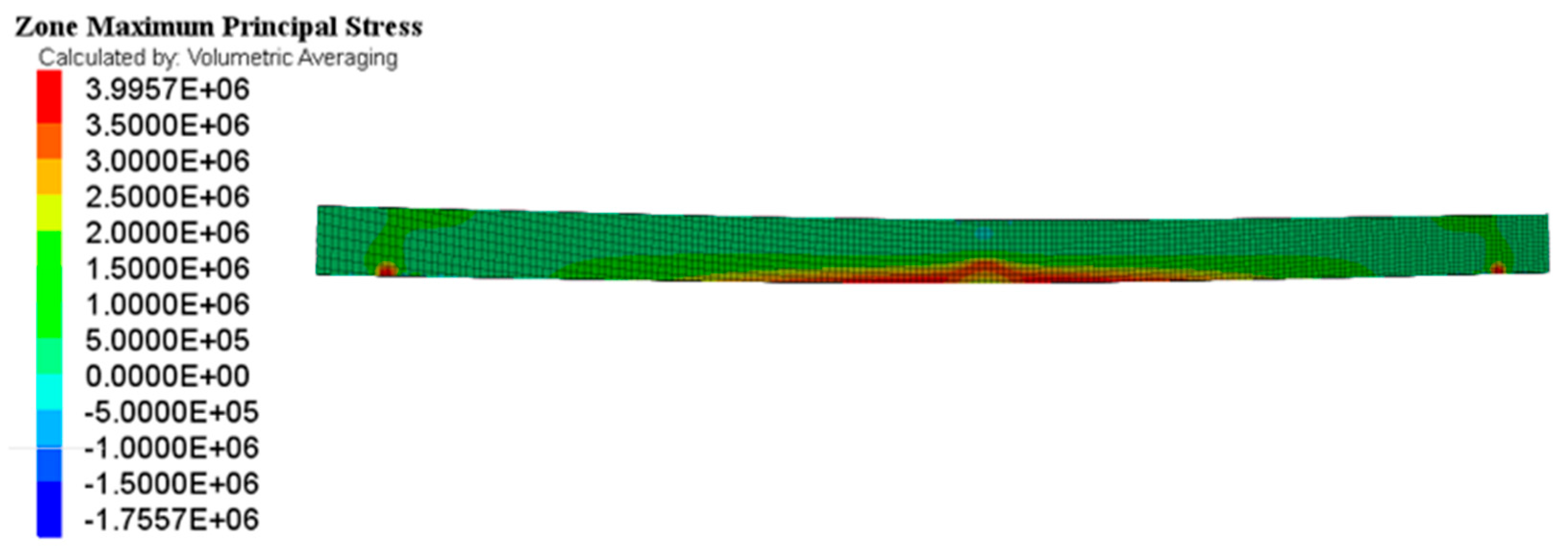
The tensile stresses (maximum principal stresses, following the sign convention of the FLAC3D software) within the beam are depicted in
Figure 11. The highest values, located at the base, reached 3.99 MPa, which corresponds precisely to the material’s tensile strength. This explains the progression of this failure mode, as shown in
Figure 10.
The flexural behaviour of printed material differs significantly from that of the homogeneous material, as evidenced by
Figure 12, which depicts the failure state. In this case, although failure initiates by tension at the base, it predominantly propagates through the joints, either by shear or tension, and extends mainly through the central section of the beam, where the neutral fibre should be located.
An analysis of the tensile stress distribution, shown in
Figure 13, reveals that these stresses do not exceed 3.2 MPa. Consequently, this value can be considered representative of the tensile strength of the printed material, and it is up to 20% lower compared to 4 MPa for the homogeneous material.
This result is consistent with the reduction observed in the ultrasound velocity perpendicular to the layers with respect to that of the homogeneous material (also 20%), which shows that there is a correlation between the two (although this cannot be evaluated as only one case study is available). It would be very interesting in the future to be able to correlate both results, since a non-destructive test (ultrasound) could be used to estimate the tensile strength of the printed material and its homogeneity.
3.2. Issues to Consider During Layer Deposition
One of the most important considerations in additive manufacturing is obtaining a material that, while being pumpable and extrudable, can also be stacked without causing unacceptable deformations. Adequate stackability enables continuous construction, without pauses for the material to harden prior to a new deposition.
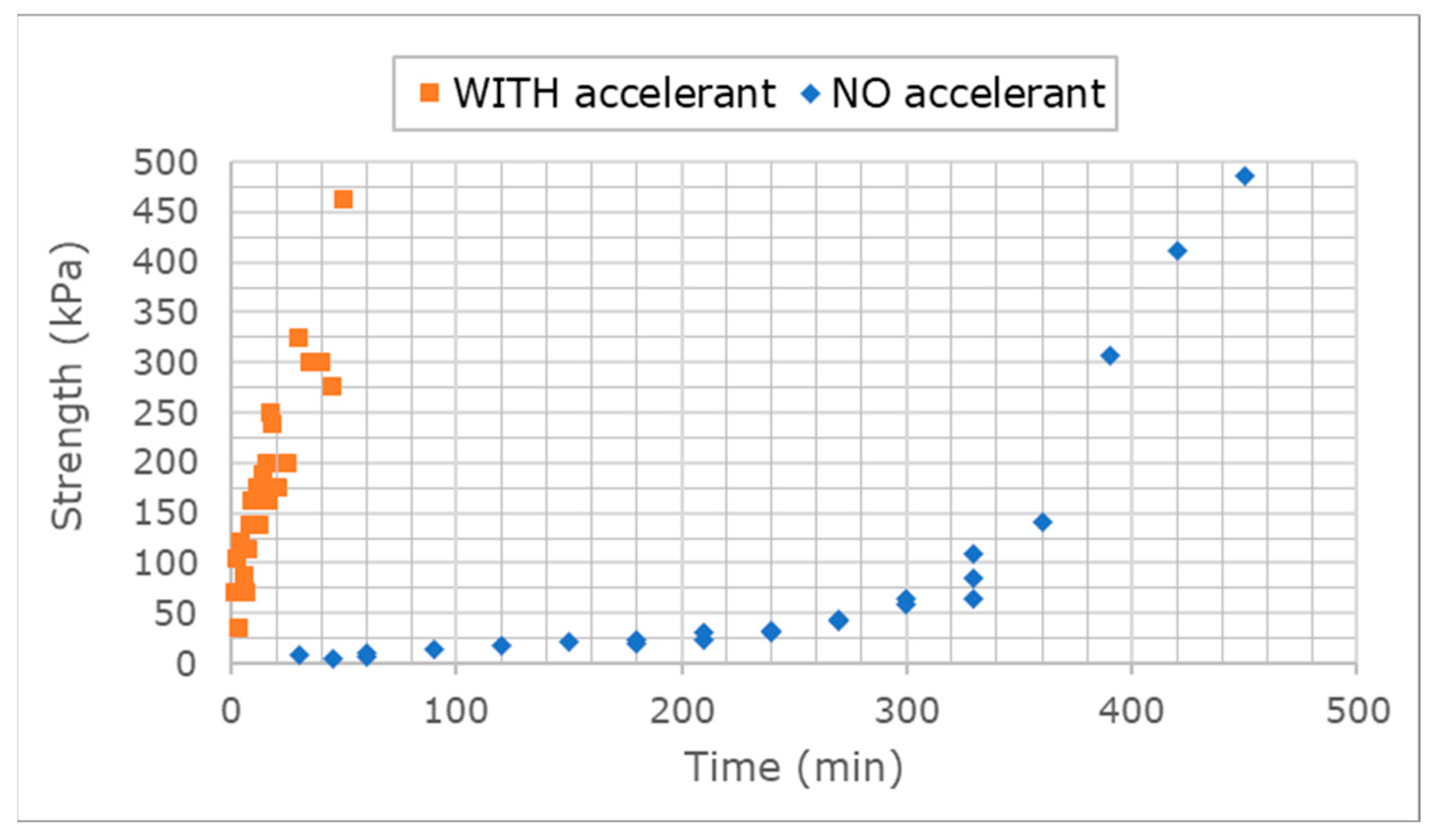
To characterise the strength of the mortar used in this study and its evolution over time, tests were conducted using a handheld penetrometer. Based on the results obtained, shown in
Figure 14, with strengths of approximately 10 kPa up to 100 min, a decision was made to assess the effect of adding a 2% accelerator, MasterRoc 167 SA, to the mixture.
As can be seen in
Figure 14, very high-performance levels are achieved in a short period which should significantly improve the stackability. Resistances of up to 100 kPa were achieved in approximately five minutes. These levels are comparable to the requirements specified in the European Standard EN 14488-2:2006 [
37] for certain types of sprayed concrete (100 kPa at ten minutes), which must attain early strength to be utilised as support in underground works. This indicates that the designed mixture exhibits an exceptional short-term mechanical performance in comparison to conventional mortars.
To evaluate the improvement in the stackability of mortar layers when incorporating this accelerator, a new computational simulation was performed using FLAC3D.
The simulated model consists of three layers, each measuring 5 cm in width, 5 cm in height, and with a total length of 30 cm, stacked vertically. To simulate the joints between the layer, ‘interface’ elements programmed in FLAC3D were utilised between the three modelled layers. These ‘interface’ elements allow the simulation of discontinuities in behaviour.
Figure 15 illustrates the geometry of the model, including the reference axes and the arrangement of the interfaces. Once the three layers are stacked, the deposition of subsequent layers is simulated by applying an overburden load on top of the upper layer.
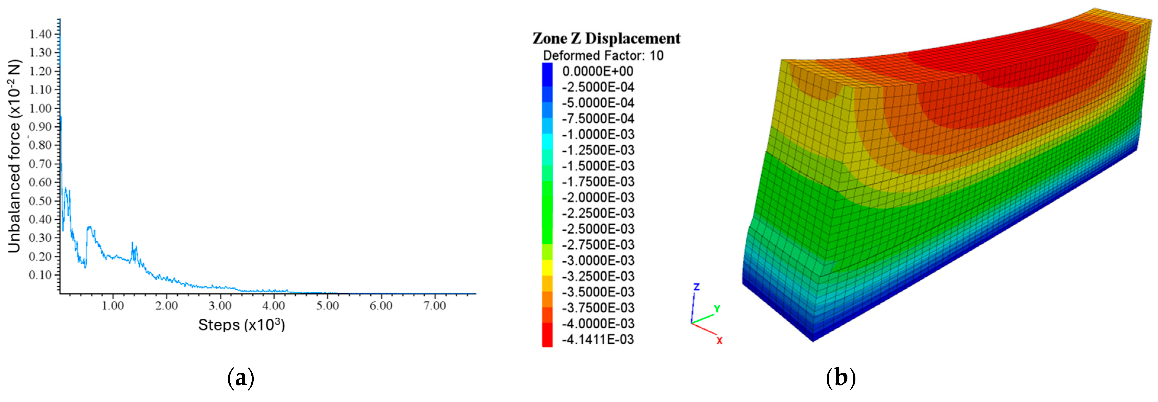
The deposition of three fresh material layers reaches numerical equilibrium, as shown in
Figure 16a. This figure depicts the evolution of the unbalanced force residuals throughout the calculation process. The unbalanced force residual is an indicator of numerical convergence in the computational procedure, which in turn is related to the physical stability of the simulated process. In
Figure 16b, the vertical displacement (along z-axis showed in the figure) experienced by the layers due to their own weight is illustrated. This displacement, approximately 0.5 cm, aligns well with the actual measurements obtained during testing. Negative sign indicates a displacement in the negative direction of the z-axis. In the figure, the deformation has been exaggerated ten-fold to facilitate clearer visualisation.
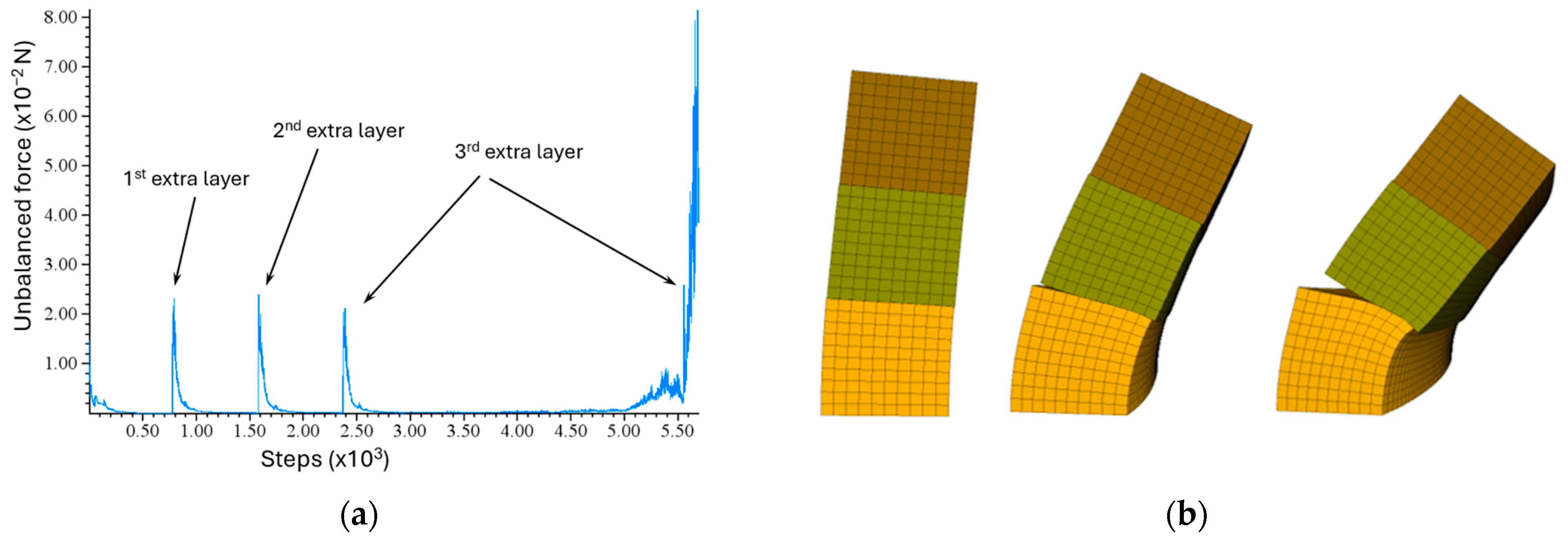
Once the first three layers are stacked, the deposition of subsequent layers is simulated by applying an equivalent overburden load on top of the uppermost one. Consequently, when an additional layer is deposited, a new vertical stress is generated. Each extra layer introduces an overburden, and an increase in unbalanced forces (due to the applied overburden of the extra layer) is observed, which gradually converges to zero during the calculation process. However, as shown in
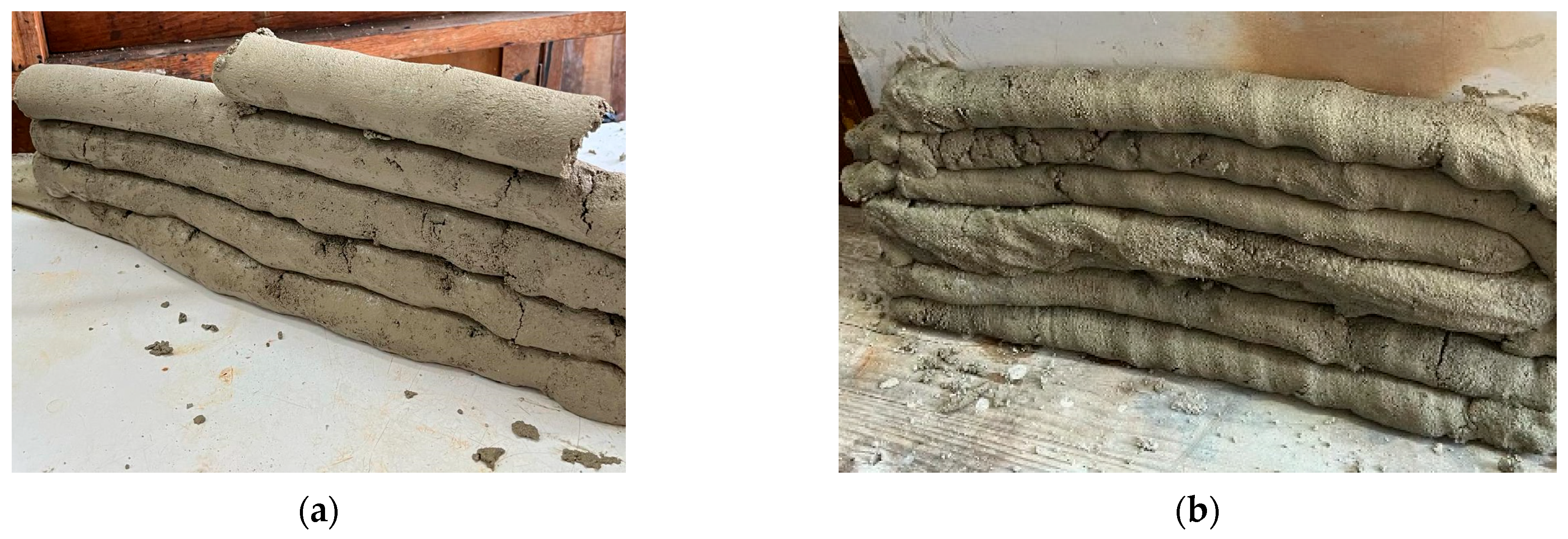
Figure 17, the system remains stable up to five stacked layers, collapsing upon the placement of the sixth.
This situation aligns with the experimentally observed data, as it was possible to stack five layers of fresh mortar (
Figure 18a); however, in order to stack a sixth layer, it was necessary to repeatedly utilise a lateral support surface (
Figure 18b).
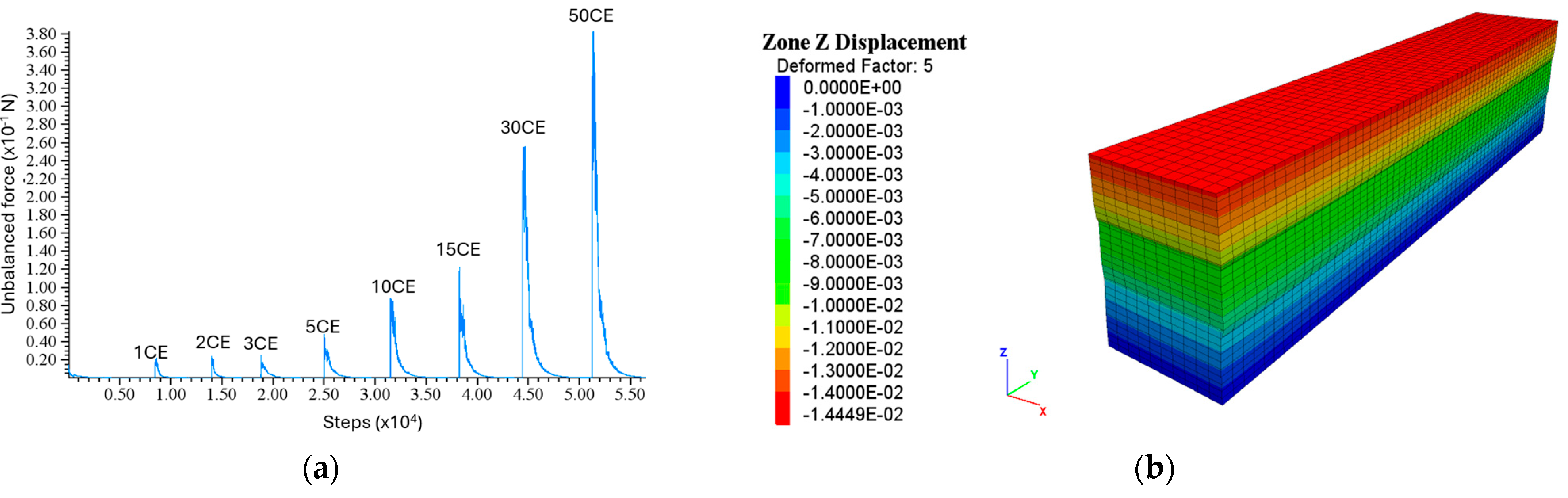
If it is assumed that the deposition of three consecutive layers requires five minutes and that the material has been supplemented with an accelerant, it is possible to simulate the improvement in the process afforded by the successive setting of the cords. To achieve this, the properties of the initial layers are progressively enhanced as additional loads are applied, which would simulate the presence of extra layers. This approach allows for the stacking of additional cords without stability issues. In fact, the use of material containing an accelerant would enable the stacking of more than 50 extra cords, thereby reaching heights exceeding 2.5 m, as illustrated in
Figure 19. In this figure, it can be observed how numerical convergence is achieved after an extra cord (1CE), 2 (2CE), 3, 5, 10, 15, 30, and 50 extra cords (50CE).
Figure 19b demonstrates the effect of the fifty extra cords on the first three cords, which would generate a vertical displacement of 1.4 cm (the legend on the left represents these displacements in metres, and the negative sign indicates a displacement in the negative direction of the z-axis, depicted in the same figure). It should be noted once again that during the progressive increase in height, the properties of the initial cords would have further improved, meaning that this displacement is significantly greater than what would be expected in reality.
These results highlight the necessity of accelerating the setting process if continuous printing is to be achieved. To prevent the use of accelerators from affecting the workability of the material and to avoid the risk of setting blockage during pumping and extrusion, these tests have worked with an ultra-rapid accelerator injected directly into the nozzle, where it mixes intimately with the mortar.
Although the accelerator increases the cost of the printable mortar, the dosages required are very low. Successful tests have been carried out with 2% by weight to water, which is about 6.1 kg of accelerant per cubic metre of mortar. This means that the impact on the final cost is small, around 6 €/m3, which is perfectly acceptable if it is possible to increase the printing speed, making it practically continuous.
Indeed, with a printing robot at a speed of 6 m/min, considering that the material allows 3 layers to be stacked every 5 min, the robot could print up to 30 m in length distributed over three layers every 5 min, i.e., a perimeter of 10 m with a height of 15 cm. It would, therefore, take less than 17 min to reach a height of 2.5 m over the entire 10 m perimeter. In other words, a room of 2.5 × 2.5 × 2.5 m could be built in less than 20 min. The implications of using this type of accelerator go even further, as it allows several robots to combine to print larger rooms in the same amount of time. Until now, the combined use of several robots was limited, as a minimum amount of time was needed to stack one layer on top of another, in many cases, even making it necessary to stop the process every 4 or 5 layers. With this system, two robots working in series could be used to print a 5 × 5 × 2.5 m room in the same 17 min, or four robots for a 10 × 10 × 2.5 m structure, because the stacking speed will be always three cords every five minutes (around 3 cm/min).
3.3. Implications on Fire and Seismic Situations
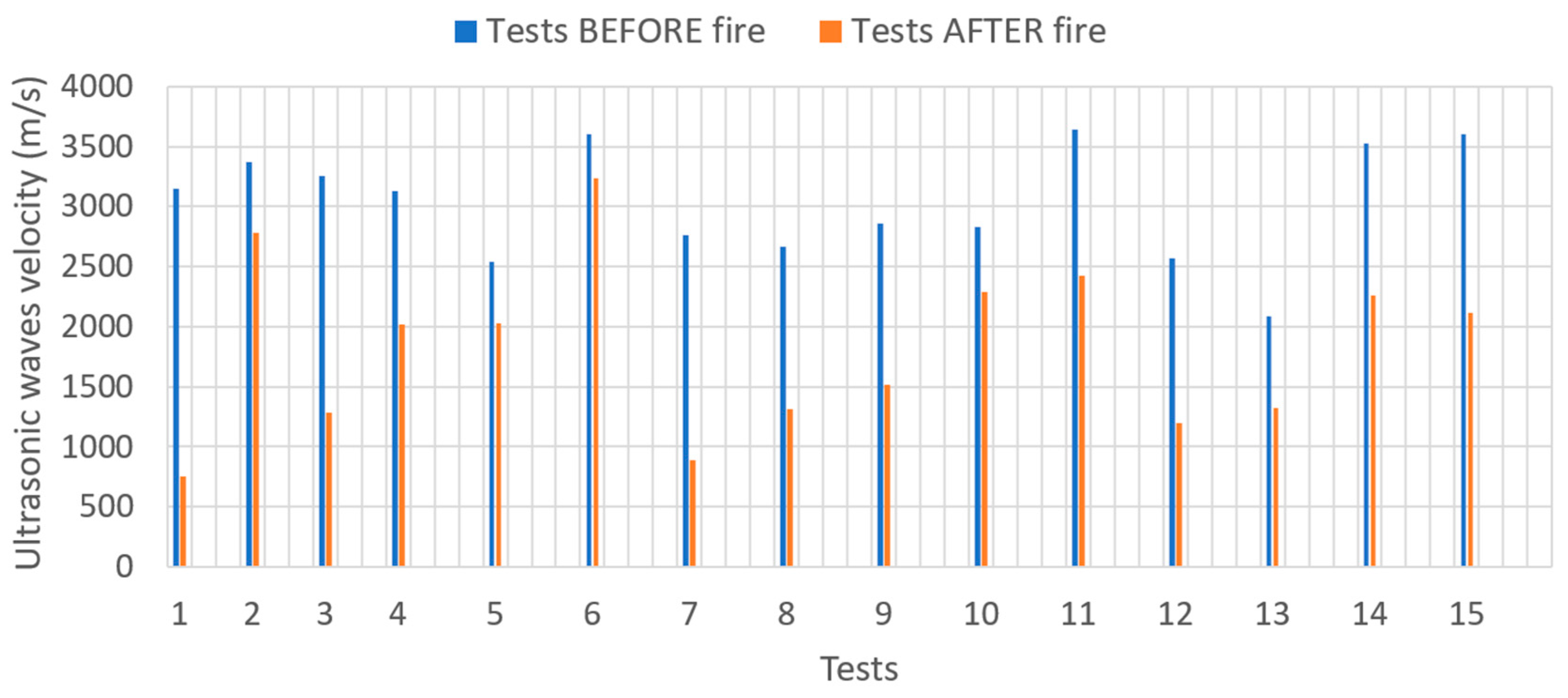
A total of 15 specimens manufactured with three and four layers were subjected to direct fire for over four hours. Thermocouples installed within them confirmed that temperatures of 250 °C were reached. Prior to the tests, the longitudinal and perpendicular ultrasonic wave velocities to the layers in each specimen were measured. After the fire exposure, measurements were repeated to detect potential effects.
It was observed that the average longitudinal ultrasonic transmission velocity in the samples decreased to 3017 m/s from the initial 3505 m/s, representing a reduction of approximately 14%.
Figure 20 illustrates the changes experienced by each specimen tested.
Regarding the ultrasonic velocity perpendicular to the layers, it decreased from an initial mean value of 3011 m/s to 1777 m/s after the fire test (see
Figure 21), indicating a significant reduction of around 40%. Therefore, the layered structure of this type of material is highly affected by fire exposure.
Regarding the destructive tests, in all flexural tests, failure occurred along the joints between the cords, which shows that the interfaces represent a weakness compared to the original material and that results are, therefore, directly comparable with those obtained in the chisel tests, representing the joints adhesion.
Table 2 presents the average strengths obtained, categorised according to the testing modality for both the flexural and chisel tests. Strength reduction is according to the ultrasonic waves velocity reduction.
Although a more detailed and in-depth study is necessary to evaluate the causes of this reduction in mechanical properties, it is important to highlight that the material’s behaviour in fire conditions should be examined more thoroughly due to the implications on potential structural damage.
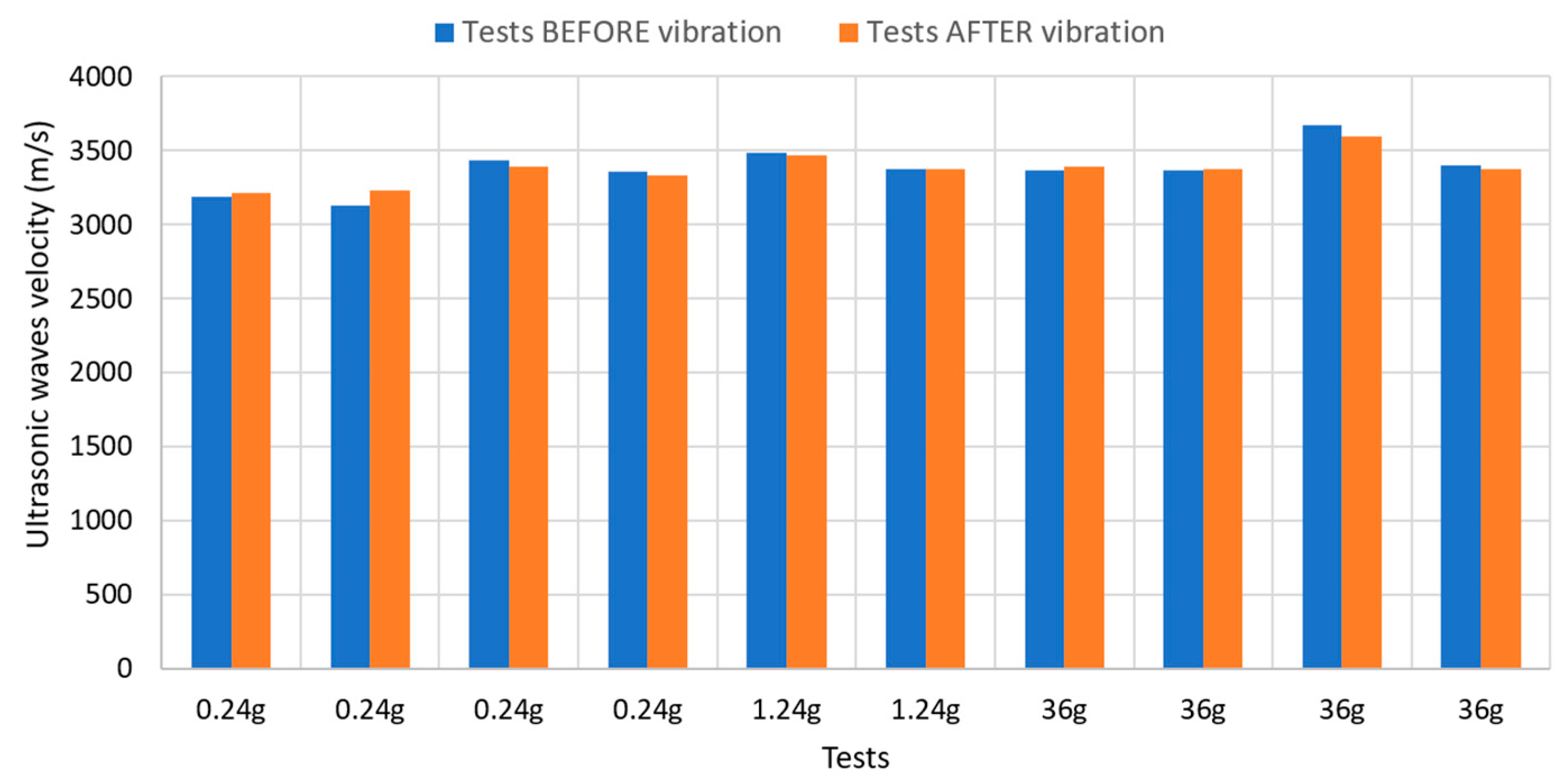
Furthermore, the behaviour of the material under dynamic phenomena was analysed by subjecting specimen samples of printed material to dynamic loadings, followed by an assessment of their resistance performance. Two different vibration amplitudes were selected: one corresponding to the most adverse scenario as specified by the Spanish Seismic Design Standard NCSE-02, which is equivalent to 0.24 g, and one corresponding to the maximum earthquake of category IX according to the Mercalli scale, amounting to 1.24 g. Additionally, tests were conducted with accelerations significantly higher, reaching up to 36 g. This high value has no real seismic meaning but has been used in an attempt to reproduce a situation where significant damage to the homogeneous material could occur, as an upper limit. The duration of the vibration was one minute. The results can be seen in
Figure 22.
In none of the scenarios considered was a reduction in the longitudinal ultrasonic transmission velocity observed, as can be seen in
Figure 22. Therefore, it appears that the vibration, under the tested conditions, does not affect the mortar itself.
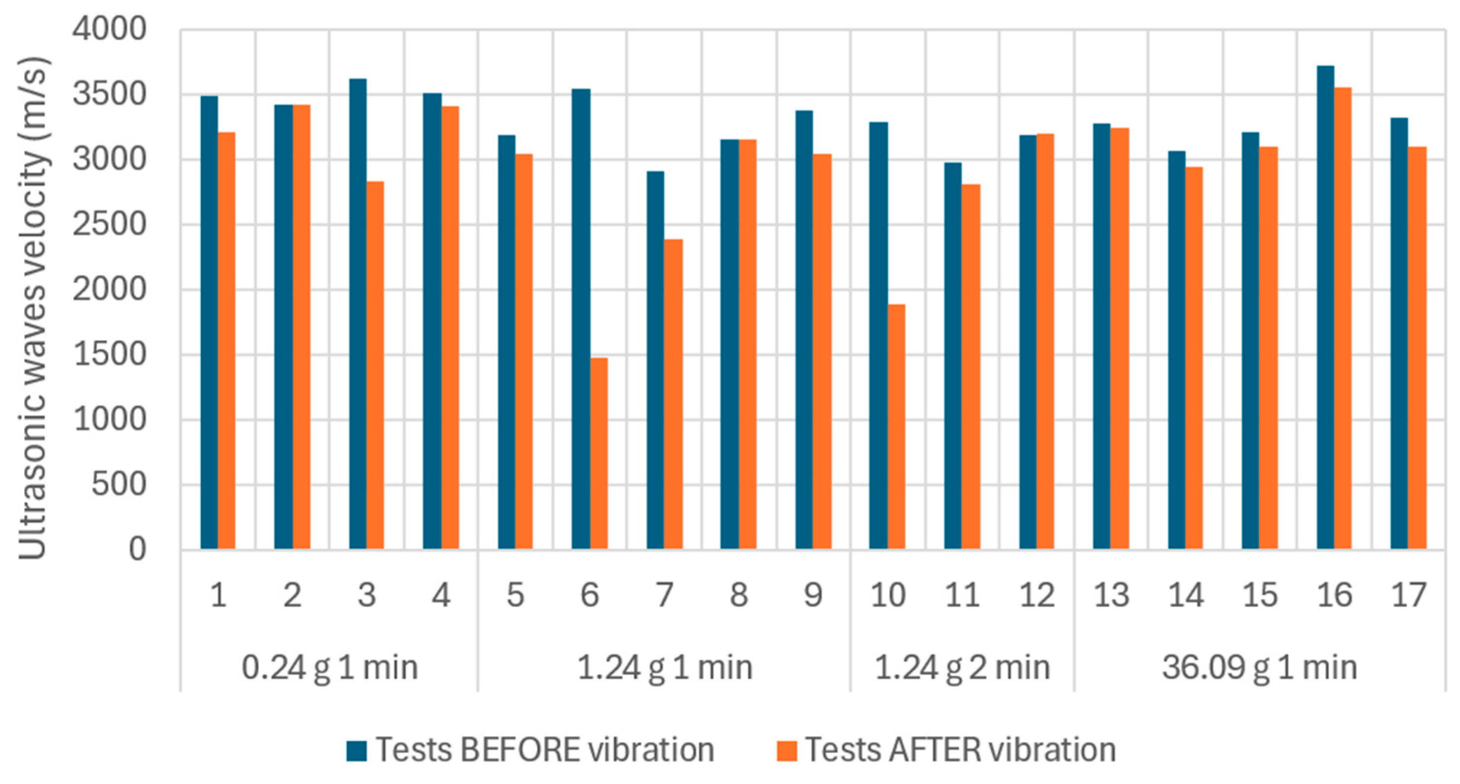
The behaviour of ultrasonic velocities perpendicular to the joints shows a slight decrease in velocity (see
Figure 23). In this case, the effect of increasing the vibration duration to two minutes at an amplitude of 1.24 g was also examined.
This potential reduction in interfacial resistance was verified through chisel tests. These tests yielded an average resistance value after vibration of 0.93 MPa (for a vibration amplitude of 0.24 g), approximately 0.8 MPa (for a vibration amplitude of 1.24 g), and an average value of 0.6 MPa for vibration amplitudes of 36 g. In other words, while the mortar remained unaffected by vibration, the joint does not, resulting in a decrease in its resistance.
Table 3 summarises the evolution of the resistance at the interfaces subjected to fire and vibration.
4. Conclusions
This study demonstrates the feasibility of utilising one type of mining tailings derived from flotation processes as recycled aggregate in printable mortars. In doing so, it highlights the contribution of 3D printing to the circular economy, encompassing both the concepts of ‘reduce’ and ‘recycle’.
Furthermore, particular aspects to consider before, during, and after construction are emphasised, especially those related to the implications with the use of materials with a layered structure.
Using numerically calibrated models, based on prior experimental campaigns, the behaviour of structural elements subjected to compression, combined compression and shear, or bending were examined. The influence of interfaces on structural design was evaluated. It has been established that, with the tested mortar, the flexural strength of a structural element would decrease by approximately 20%, whereas in elements subjected to compression and shear, the resistance could diminish by up to 33%.
Additionally, during the construction process, the strength and deformability of the deposited layers influence the buildability and, consequently, the construction speed. Laboratory tests on fresh mortar, combined with a computational numerical model confirm that by adding 2% MasterRoc 167 SA accelerator, three layers can be stacked every 5 min, so that a 2.5 × 2.5 × 2.5 m room could be printed in less than 20 min without having to stop the process every four or five layers. Moreover, the system allows several robots to be combined so that larger constructions could be tackled without reducing the stacking speed, which would still be three cords every five minutes (about 3 cm/min). The added cost is estimated at around 6 € per m3 of mortar, which is entirely affordable given the advantages.
Finally, aspects related to the performance of structures fabricated via 3D printing during their operational phase under special conditions—such as fire or seismic events—were addressed. Through two experimental campaigns, it was demonstrated that both scenarios can significantly affect the interface strength between layers, reducing it by as much as 50 %.
Future Work Areas
This work, more than being a final point in the investigation of the viability of recycling mining tailings as aggregates for 3D printing, opens new ways for research.
It is advisable to reinforce the validity of the DEM models with a sensitivity analysis that allows for better understanding of the influence of bonded surface strength on both the structural elements and early stages behavior. Moreover, the possibility of finding a correlation between the reduction of the ultrasonic velocity perpendicular to the layers and the reduction in the flexural strength of the printed parts should be explored, as it would allow the use of non-destructive testing to estimate the strength of the parts.
Early strength is highly dependent on the type of accelerator and its dosage. In the future, it will be necessary to optimize both based on the type of structure and construction planning, since slower accelerators or lower dosages may be suitable depending on the desired speed of raising the structure.
Moreover, a deeper analysis of fire and seismic damage should be conducted. A larger testing campaign with different fire conditions evaluating mass loss, microstructure destruction, or the development of microcracks needs to be carried out in order to understand the degradation mechanism. Similarly, in the seismic study, the time ranges for applying dynamic loads should be expanded.
Finally, the characterization of the bonded surface between layers after failure in bending and chisel tests is necessary to determine its residual strength, both under normal conditions and in fire and seismic loads. This, in turn, helps assess the residual strength of the structural elements.


 ,
, 


