Abstract
In this work, the effects of the mixing water loss capacity of hydrated lime mortars with different dosages were analysed—type O (mix 1:2:9), type N (mix 1:1:6), and type M (mix 1:0.5:4.5), with additions of submerged arc welding (SAW) slag. Infrared thermography tests and optical and scanning electronic microscopy analyses of the mortars were also carried out. The experimental results showed that the mortar samples with additions of SAW slag type M, using low-cost materials, proved to be in economic and technical terms (adhesion strength) the best solution, even more so if a spatter dash layer is used, a fact that increases the adhesion strength even more. Also, the infrared thermographic results revealed that the ability of the mortar paste to yield water to the ceramic substrate in the interface regions is a relevant factor in the adhesion of these coatings. Finally, the analyses by scanning electron microscopy and optical microscopy revealed that the ability to release water to the substrate is related to the hydration of the mortar and its anchoring capacity. Furthermore, the analyses carried out demonstrated that the adhesion of the mortars is influenced and increased with the application of a layer of splashes, as the pores of the substrate become more refined and better filled with the applied mortar.
1. Introduction
Modern society has, over time, increased the consumption of products that generate waste, of which we can highlight the consumption of products based on metallic alloys [1]. Taking into account the large production of waste generated by society, it is expected that, based on the interaction between the different areas of global research, alternatives will be identified for the efficient reuse of industrial waste, not only to mitigate industrial impacts on the environment but also to add value to materials, reducing production costs and reusing them, in line with what is foreseen in the Sustainable Development Goals (SDGs).
Considered only solid waste, in the last decade Brazil produced approximately 750 tons of submerged arc welding (SAW) slag resulting from the welding processes, according to [1,2]. Proper disposal of this waste generates high costs for the economic sector; however, its reuse can add value to the waste, as discussed by [3], where palliative alternatives are presented to discuss possible reuses.
As an example, the submerged arc welding process uses a granulated flux that protects the molten pool against contaminants, in addition to adding alloying elements that contribute to the mechanical properties of the welded joint. During welding, this flux, which contains lime, SiO2, MnO, CaF2, among other compounds, reacts with the contaminants in the weld metal and melts, forming slag [4].
Industry in general and the construction industry in particular will face major challenges soon, such as generating new products that can combine satisfactory results in terms of specific performance with durability [5]. In more detail, among the various construction systems used in civil construction, the mortar coating system on the facades of buildings is one of the most challenging [6]. According to several authors [7,8,9], the functions of the hydrated lime mortars that are widely used in construction have specific functions and specific performance, not limited to merely aesthetic functions [8]. One of these important functions is the protection of structures against external agents, delaying the advance of these aggressive agents, such as attacks by chlorides, CO2, and infiltrations of leaching products that maintain high pH levels, among other attacks, thus protecting the reinforcement. A relevant factor in the deleterious attacks on structures by aggressive agents is associated with the heat of hydration since in exothermic reactions thermal control is fundamental to mitigate cracks [10].
According to [11,12], several methodologies and strategies are used to improve the adhesion of hydrated lime mortars in buildings. One of the commonly used methodologies consists of applying a spatter dash layer, containing Portland cement sand, before applying the hydrated lime mortar. In other words, the main difference between this material and the hydrated lime mortars is the absence of hydrated lime. According to [13], the main advantage of applying the spatter dash layer, when compared to applying the hydrated lime mortar directly to the substrate, is the faster curing time to obtain the hardened state. Therefore, its use is quite advantageous because it increases productivity and saves time as a whole. The waiting time for the spatter dash to cure is approximately 3 days, while the corresponding time for hydrated lime mortars is approximately 1 week [14].
Moreover, aiming to analyse the different stages associated with the execution of coatings in buildings, as well as their performance in terms of service life, several studies can be found in the literature referring to numerous performance evaluation techniques, such as infrared thermography analysis [13]. This easy-to-use technique is quite effective in studies with cementitious materials, allowing the identification of infiltrations in specific situations on the internal walls of buildings.
In order to increase the quality and durability of mortars used on facades, several researchers have developed works that report the addition of metakaolin [15,16], carbon fibres [17,18,19], active silica [20], recycled materials, such as glass [21], asphalt [22], plastic fibre as aggregate [23] and concrete [24], among others, as a way to increase adhesion strength. Mineral additions, such as metakaolin, are a strategy used to intensify and improve some properties of mortars, such as the mechanical properties (compressive strength) and porosity of the material, which tend to decrease as voids are filled [15,16].
Another highly relevant property in mortars applied to building coverings is their ability to adhere to substrate surfaces, for example, when applied to ceramic blocks. In this sense, the work developed by [25] showed that the use of different types of sand influences both the consistency and density of the coating mass. In this study, the correlation between the voids in the sand grains (porosity of the material) and the consistency of the material was evidenced, influencing the adhesion of the mortar on a given substrate. Another property reported by the authors that also negatively affects the adhesion of mortars is the material’s water absorption capacity. However, although sand plays a highly important role, other materials are also used in the production of mortars, such as Portland cement, CH I hydrated lime, and, when necessary, mineral additions, so further research is necessary to analyse the problem described in more detail.
Research Significance
In this work, the aspects of the interactions and the ability to yield free water, present at the time of mixing and application to the substrate in its fresh state, were evaluated, with and without the preparation of the substrate through a spatter dash layer. Additionally, the impacts associated with the preparation of mortars with additions of SAW slag were evaluated in terms of physical properties, such as adhesion strength. Subsequently, to evaluate the possible ability to provide the kneading water to the substrate, the infrared thermography technique was used, in order to explain the adhesion phenomenon. Finally, the mortars were evaluated from a microstructural point of view, using X-ray efflorescence (XRF), scanning electron microscopy (SEM), and optical microscopy techniques, observing aspects of the influence of the mortar’s water transfer capacity on ceramic masonry walls with and without spatter dash.
In summary, this work presents a very useful tool for the evaluation and application of mortars, through infrared thermographic analysis, considering that the applications of large quantities of these materials (mortars) are applied to the facades of buildings. Furthermore, when associated with regions with a tropical climate, such as coastal cities in Brazil, the performance of the technique and the adhesions of mortars with additions of submerged arc welding (SAW) slag, were quite favourable.
2. Materials and Methods
The mortar samples were prepared with Portland cement, type CP II Z 32, medium and coarse sand, hydrated lime CH I in different percentages, and water, for a water/cement ratio of 1.401, following the Brazilian standard [26]. The samples were also prepared with additions of 5% (in mass) of submerged arc welding (SAW) slag. This percentage of SAW slag selected is based on research carried out by our research group, obtaining increases in the mechanical properties of cementitious matrix composite materials with additions of SAW slag [27]. The ceramic blocks, with dimensions of 9 × 19 × 19 cm3, were used to produce masonry samples with 1 m2. The spatter dash used was prepared with a mixture of Portland cement and coarse sand in a ratio of 1:3, meeting the standard criteria [28]. Similar to spatter dash, hydrated lime mortars were prepared and applied to substrates after the curing time intervals provided by the Brazilian standard [28]. Regarding the application of the hydrated lime layer on the three masonry, corresponding to six walls (using the two phases of the masonry), three types of hydrated lime mortar dosages with additions of SAW slag were prepared: (a) 1:2:9 (Portland cement:CH I hydrated lime:Sand) for mortar type O; (b) 1:1:6 for mortar type N; and (c) 1:0.5:4.5 for mortar type M, as detailed in Table 1. All mortars analysed were applied on ceramic block masonries, with and without spatter dash (see Figure 1).

Table 1.
Detail of the mortar dosages used.
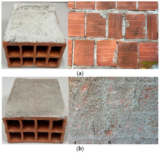
Figure 1.
(a) Mortar applied directly to the ceramic block after 120 min (case T1); (b) Mortar applied on the substrate prepared with spatter dash after 120 min (case T2).
The motivation for choosing the proportions was based on the experiences of works in general, especially vertical works with applications on facades and also for applications in small residences, which require large quantities of mortar in tropical countries, with average facade temperatures of 58.7 °C.
In order to analyse the influence of free water that is transferred from the mortar with additions of SAW slag to the ceramic block masonry under study, tensile adhesion strength (Tas) tests of the coatings applied to the ceramic block masonry were carried out, after a curing time of 28 days. To carry out the tensile adhesion strength tests of the hydrated lime mortars, it was necessary to score 12 points on each wall, according to the Brazilian standard [29]. After that, the cuts were made with an internal diameter of 50 mm, and using a drill and a hole saw [29]. A force transducer (Alpha Instruments, model Z2T) with a nominal range of 20 kN, associated with a digital electronic instrumentation (Alfa Instruments, model 3105C) with a nominal range of five digits and 1 point, was used. The experiments to analyse the water retention at the time of hydration of the coatings were carried out using a thermographic camera (model FLIR E60), in order to measure the relative humidity and the temperature before and at the time of application of the hydrated lime mortar with additions of SAW slag, applied directly to the ceramic block with and without a spatter dash layer.
For a better use of the thermographic camera, the equipment was personally adjusted by manually adjusting the equipment’s focus, as well as determining the relative humidity (RH) and ambient temperature using the Digital Thermo-Hygrometer—MTH-1360ª.
The microscopy analyse was conducted in order to evaluate the morphological aspects obtained through the images. For semi-quantitative analysis, 50 measurements of pore sizes were carried out, obtaining an average of pore sizes for each sample of mortars with additions of SAW slag, type O and M. This experimental campaign was carried out using the optical microscope equipment (Olympus BX51), the images were obtained using objective lenses with magnifications ranging from 5× to 100×, and all images were generated using AnalySIS imager software v6.1. This experimental campaign was carried out using the optical microscope equipment (Olympus BX51) with a magnification between 5× and 100×, and all images were generated using AnalySIS imager software. For the microscopy analyses, a TESCAN scanning electron microscope, model MIRA3, was used, with a main electron beam generated from a tungsten filament with a voltage of 10 kV, SE and EDS detectors, and a working distance of 40 mm. The samples analysed were used in a Stub with carbon tape and metallization to make them conductive. For point chemical analyses (EDS) and map generation, an OXFORD-type detector (X-Maxn) was used. X-ray Fluorescence (XRF) was used to determine the chemical composition of the slag samples (SAW) and the precursor inorganic materials (with dimensions of 30 mm) were prepared by applying a load of 150 kN over 1 min. Subsequently, the samples were dried in an oven at 90 °C. All XRF experiments were performed by using an XRF 1800 Shimadzu equipment.
3. Results
3.1. X-ray Fluorescence Spectrometry (XRF)
Chemical, mineralogical, and morphologic composition of SCBA in anhydrous state. The chemical composition of the samples of SAW and Portland cement are represented in Table 2.
Table 2.
Chemical composition of materials (SAW and Portland Cement).
According to ASTM [30], the samples of SAW analysed in this research are according to the chemical requirements for pozzolanic materials Class C (equivalent to NBR 12653, [31], Class E). It is important to highlight that even if a material complies with the classification of pozzolanic material, regarding chemical composition, it may not be a pozzolan if it is not composed further by other analyses must be carried out.
3.2. The Adhesion Strength Bond (Tas) of Mortar Coatings Applied to Ceramic and Spatter Dash/Ceramic Substrates
Table 3 and Figure 2 present the experimental results of tensile strength tests to evaluate the mechanical adhesion properties of mortars with additions of SAW slag, applied directly on a ceramic substrate (case T1), and on a spatter dash mortar layer (cement/sand ratio of 1:3) previously applied to the ceramic substrate (case T2).
Table 3.
Adhesion strength values (Tas) of mortars with additions of SAW slag applied directly to a ceramic substrate (T1) and on a surface with a spatter dash layer (T2).
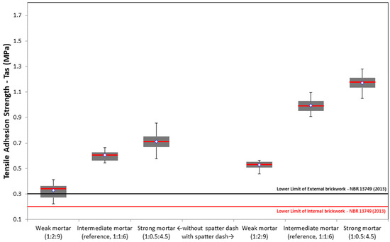
Figure 2.
Tensile adhesion strength results, after 28 days.
The results presented in Table 3 and Figure 2 show that the coefficient of variation was higher for mortar type O (17.62%) in comparison to the other mortars with additions of SAW slag and without spatter dash application (T1). It was also possible to observe that the mortar samples analysed presented an increase in their strength values (Tas), with a reduction in the amount of hydrated lime. These results were also observed in the tests with different types of mortar with additions of SAW slag and spatter dash application (T2) in accordance with results presented in the literature [10,32,33]. The results also showed an adhesion strength increase when the substrate is prepared with the application of spatter dash, before applying doped mortars with SAW slag. This result is following previous experimental results presented in the literature [34,35], and it is explained by a purely physical phenomenon, due to mechanical anchorages [32]. However, this explanation based only on physical anchoring is quite simplistic because, in addition to there being physical anchoring interactions, there are also changes in the chemical bonds associated with the phenomenon of adhesion, which we will present later.
It should be mentioned that the tensile adhesion strength results obtained were higher than those established as lower limits by NBR 13749 [29], both for the cases of internal and external walls (≥0.2 MPa and ≥0.3 MPa, respectively), and higher than the values reported by [5,6,7], showing that SAW slag has a significant influence on increasing the adhesion strength (Tas) of the samples. An increase in the adhesion results of all mortar samples with additions of SAW slag was observed, demonstrating that there is an interaction between the mixtures and the additions of SAW slag. These results showed that the doped mortars interact positively with the mixture as well as with the surface of the applied substrate, both for cases T1 and T2. This result is in accordance with previous research presented by [27], who used submerged arc welding slag in mortars, and showed the feasibility of using SAW slag in the production of mortars
The rupture zones in the tensile adhesion strength test were observed and identified, which for the majority of samples, in case T1—without spatter dash, occurred in the hydrated lime mortar (see Figure 3a), that is, the detachment of the substrate occurred with the abrupt rupture of the hydrated lime mortar. However, for the mortar samples type M (mix: 1:0.5:4.5), in case T2 (with spatter dash), it was possible to observe that the rupture was predominantly in the substrate layer, as the spatter dash layer increases the adhesion strength values [32,34] (see Figure 3b). However, for mortar samples type M, in case T1, the rupture occurred in different zones, such as the hydrated lime mortar, spatter dash, and substrate (see Figure 3c).
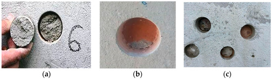
Figure 3.
(a) Rupture in hydrated lime mortar; (b) Rupture in substrate layer, and (c) Rupture in hydrated lime mortar and spatter dash.
In Figure 2 it is possible to observe that all the results obtained were higher than those established as lower limits by [16], both for the cases of internal walls and external walls. Furthermore, all samples have values higher than those found by [5,6,7]. An increase in all adhesion results of all mortars with (SAW) was also observed, demonstrating that there is an interaction between the mixtures and the additions of submerged arc welding slag. The results also revealed that the mortars interact positively with the mixture as well as with the surface of the applied substrate, both for the case situation (T1) and for the case situation (T2), thus presenting results superior to those found [5,6,7] in their mortars without SAW doping. When comparing with the results obtained [5,6], it is verified that the submerged arc welding slag (SAW) has a significant influence on the increase in the adhesion strength (Tas) of the samples.
This result corroborates the results observed by [27] in his research for tensile strength, where submerged arc welding slag was used in the mortars, with the percentage of mass addition, obtaining favourable results, thus concluding the viability of using slag (SAW) in the production of mortars.
3.3. Infrared Thermography Analysis
The analysis of the mortar’s behaviour applied with and without slag on the ceramic substrate was carried out using infrared thermography, on the ceramic blocks separately and with their respective applications with mortars with additions of SAW slag. Figure 4a shows the thermogram obtained with ceramic blocks previously dried and exposed to natural solar radiation. The results show that the dry ceramic blocks have an average temperature of 58.7 °C, measured at three different points. This temperature value is in accordance with works in the literature [36,37,38,39] and describes the natural ambient conditions of ceramic blocks exposed in civil construction works for the Brazilian coastal tropical climate.

Figure 4.
(a) Ceramic block thermogram in normal conditions, (b) in laboratory conditions, and (c) submerged in water for 24 h.
This extremely high-temperature value observed in the in-situ ceramic blocks contrasts with the values obtained under controlled laboratory conditions (T = 25 ± 0.2 °C) and for blocks submerged in water for 24 h, as can be seen in Figure 4b,c, respectively, with temperature measurements at 3 different points. The results presented in Figure 4c, with an approximate temperature of 24.1 °C, are expected and show the rapid absorption of water in 24 h from this porous material.
Figure 5 shows the thermograms obtained from mortars applied directly to dry ceramic blocks (substrate), without spatter dash. It is possible to observe that when mortars with additions of SAW slag are applied, there is rapid moisture absorption from the mortar by the block, through the homogeneous distribution of temperatures over time, particularly in the first 60 and 120 min. This is particularly important evidence regarding the adhesion capacity of hydrated lime mortars on ceramic block substrates [40].
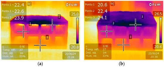
Figure 5.
Thermogram of the mortar frontal view after: (a) 60 min, and (b) 120 min.
Still to the analysis of the direct influence of the mortar’s ability to release water to the substrates in ceramic blocks, for case T2, the temperature distribution behaviour in the ceramic blocks with spatter dash was evaluated. The results presented in Figure 6 shows that the ceramic block covered with a layer of hydrated lime has a different carmine red colour tone from the ceramic block with mortar applied directly to the substrate, with a dark blue colour, which shows that the distribution of moisture in the spatter dash layer is much faster.
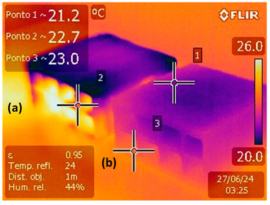
Figure 6.
Thermogram of ceramic blocks: (a) coated with a layer of mortar applied directly to the block (case T1); (b) coated with a layer of spatter dash (case T2).
This result shows that the water absorption capacity, both by mortar coatings and ceramic blocks, influences the adhesion mechanism of the coatings, and the homogeneous temperature distribution over time, until reaching the equilibrium temperature of the system, is directly related to the ability of the system spatter dash/mortar to transfer water to the substrate. In other words, the experimental results show the influence of the capacity of the mortar and the spatter dash to give moisture to the substrate on the mechanical phenomenon of adhesion, i.e., the temperature distributions are different for the two systems. It is also possible to observe that the lower temperatures tend to remain for a longer time and the samples with a spatter dash layer present a faster and more homogeneous temperature distribution, lower than 60 min (carmine red colour). In turn, mortars applied directly to the ceramic blocks maintain a dark blue colour for times longer than 120 min.
In summary, the results of the infrared thermographic analysis show the ability of the mixtures to transfer moisture to the substrate, being more efficient for samples that use a layer of spatter dash, i.e., the hydrated lime present in the mortar mixtures and which does not exist in the spatter dash layer directly influences the ability to transfer moisture to the substrate and consequently influences the adhesion strength values (Tas). Furthermore, the experimental campaign showed that there is an optimal amount of hydrated lime added to mortars (mortar type M) responsible for significant influences on adhesion strength.
Figure 7 shows that with the application of mortar on the substrate prepared by a spatter dash layer, the distribution of moisture and thermal equilibrium in the system becomes slower. In other words, the results show that over time the temperature change was slower, mainly in the interphases between the spatter dash layer and hydrated lime mortar, as the spatter dash layer exerts a momentary sealing function associated with the retention of the mortar that contains hydrated lime in its mixtures.
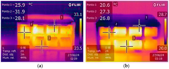
Figure 7.
Thermogram of ceramic blocks coated with a mortar layer prepared with a layer of spatter dash, at: (a) 60 min, and (b) 120 min.
Therefore, we observe that the distribution over time apparently occurs initially at the ends of the ceramic blocks, where we believe to be a point of weakness, due to the lack of precision in the application of the materials at the edges, as observed in Figure 7b.
On the other hand, it can be seen that in the first 60 min (see Figure 7a), this moisture distribution is not influenced even by the supposed fragility of the application of the materials at the edges.
3.4. Microscopic Analysis
After the infrared thermography analysis described in the previous subsection, and based on a more detailed analysis of the water transfer processes from the mortar and spatter dash systems to the ceramic blocks and their influence on the adhesion capacity of the hydrated lime mortars studied, this section, it will be evaluated through from the scanning electron microscopy (SEM) technique with SE and EDS detectors, the aforementioned effect, for mortars type O (mix 1:2:9) and M (mix 1:0.5:4.5), with additions of SAW slag. This ability of the mortar to adhere to the substrate, being classified by [41] as mechanical adhesion, was reported by several researches [42,43], as being a purely mechanical phenomenon, however previous evidence demonstrates much more complex phenomena, which must be further explored.
Figure 8, Figure 9, Figure 10, Figure 11, Figure 12 and Figure 13 show the micrographic analyses of the precursor materials, Portland cement, SAW slag, and sand used in this research, where through the SE and EDS detectors, it was possible to analyse the morphological aspects and identify the elements present, to better clarify the adhesion phenomena.
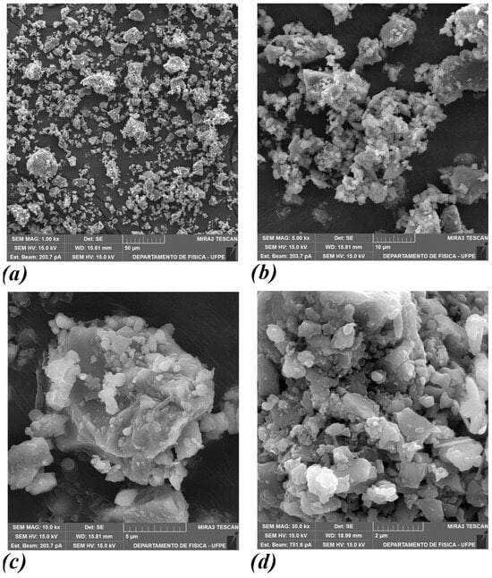
Figure 8.
SEM images of the precursor solid material, cement Portland, with a magnification of: (a) 1.00 kx, (b) 5.00 kx, (c) 15.00 kx, and (d) 30.00 kx.
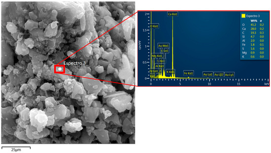
Figure 9.
A local energy-dispersive X-ray spectrum (cement Portland).
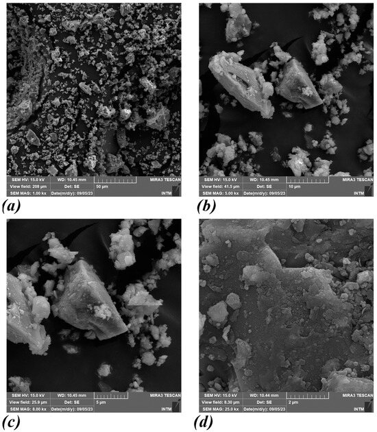
Figure 10.
SEM images of the precursor solid material, submerged arc welding (SAW) slag, with magnifications of: (a) 1.00 kx, (b) 5.00 kx, (c) 8.00 kx, and (d) 25.00 kx.
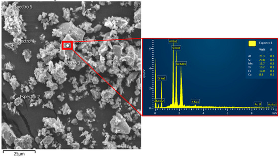
Figure 11.
A local energy-dispersive X-ray spectrum (submerged arc welding (SAW) slag).
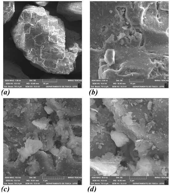
Figure 12.
SEM images of the precursor solid material, sand, with a magnification of: (a) 1.00 kx, (b) 5.00 kx, (c) 15.00 kx, and (d) 30.00 kx.
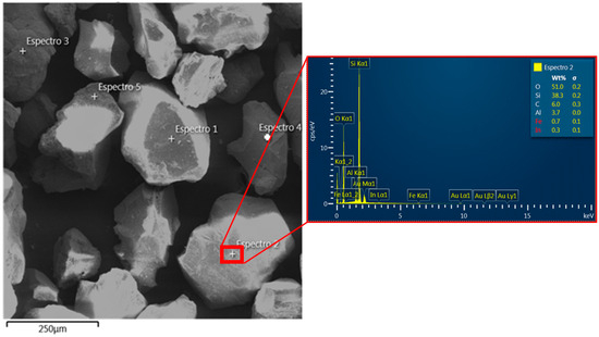
Figure 13.
A local energy-dispersive X-ray spectrum (sand).
The scanning electron microscopy (SEM) images presented in Figure 8a–d showed that the average of the cement particles is quite varied, but mostly, particles are in the range between 0.7 μm and 70 μm. Also, showed that all particulate materials are smaller than 50 µm, and it is possible to observe at higher magnifications that the particles are agglomerated (see Figure 8b–d), which is an expected result due to the high surface area of the particles., which increases the electrostatic attraction between them.
On the other hand, Figure 9 presents the results of the energy-dispersive X-ray spectrum application, it is possible to observe that chemical elements existing in greater quantities are Ca, Si, Al, and Fe, present in the main phases of Portland cement C3A, C3S, C2S, C4AF, a result widely reported by several researchers [44,45,46].
Figure 10a–d show that the average particle size of submerged arc welding slag is quite varied, but most of the particle sizes are in the range of 0.5 µm to 40 µm, and that particulate materials are smaller than 50 µm. It is also possible to observe that most of the particles are agglomerated, such as Portland cement, due to the high surface area of the particles, which increases the electrostatic attraction between them (Figure 10b–d).
Finally, when applying X-ray, according to Figure 11, it is possible to observe that chemical elements existing in greater quantities are Al, Si, Mn, Fe, Ti, and Ca, these results are similar to those found and widely reported by several researchers [3,47].
Figure 12 shows that the average diameters of the sand particulate material are in the range of 200 µm to 800 µm, consistent results for the material used (medium sand). However, when increasing the magnifications, we can observe that the dimensions of a randomly chosen grain are from 200 µm to 600 µm (Figure 12a), and, apparently, the sand particles have a lot of volumetric defects (see Figure 12b–d), which are responsible for storing moisture and impurities in their cavities. These volumetric defects of fractures, and pores, among others, vary in size with openings between 2 µm and 10 µm, which suggests a perfect storage location for impurities and moisture.
Thus, the moisture storage capacity, combined with direct contact with the Portland cement grains and submerged arc welding slag grains, which in turn are smaller than the defect openings, instantly causes exothermic cement hydration reactions and the formation of hydration products, with the hydrated phases of CSH (hydrated calcium silicate), ettringite, and Portlandite, among others, which cause anchoring [48]. These anchors cause an increase in adhesion strength, as we can see in the results of adhesion experiments obtained in masonry prepared with a layer of spatter dash (mix 1:3—sand and Portland cement).
Furthermore, it is noticeable that these cavities can, in addition to storing moisture, impurities, and cement grains, store submerged arc welding (SAW) slag, which, due to the high concentration of aluminium and silicon observed with the application of EDS (see Figure 13), contribute to the formation of the secondary CSH phase as reported by [47], with a direct consequence on adhesion strength (Tsa) and pore refinement, as observed in the results presented in Figure 2.
Thus, it is possible to verify that the phenomenon of adhesion is directly related to the ability of mortars to transfer water with particulate sediments of cement, SAW, and sand to the substrate, as previously verified through thermographic analyses. On the other hand, it is also observed that the water transfer capacity of the mortar system to the substrate and the phenomenon of adhesion are closely and directly related to factors related to the amount of submerged arc welding (SAW) slag present in the system reported by [27], hydrated lime and an amount of sand also present in the system, as well as the preparation of the substrate with spatter dash. These factors significantly increase the mechanical performance of the adhesion compared to the results obtained by other authors [25,49].
Figure 14, Figure 15, Figure 16 and Figure 17 show aspects of the morphologies of mortars with additions of SAW slag (mortar type O and type M), through micrographs, using the SE and EDS detectors, and optical microscopy, for a better evaluation and understanding of the adhesion phenomenon.
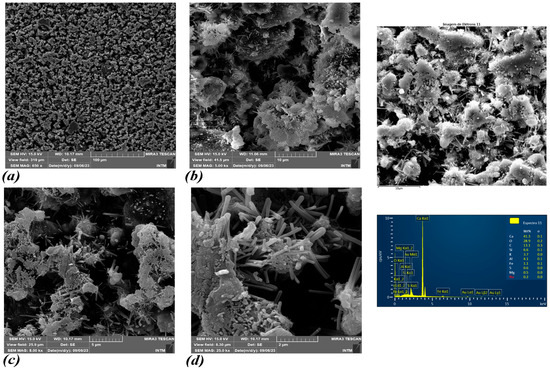
Figure 14.
SEM images of the mortar type O with the following magnifications: (a) 650 x, (b) 5.00 kx, (c) 8.00 kx, and (d) 25.00 kx.
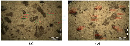
Figure 15.
Optical microscopy technique of mortar type O with additions of SAW slag: (a) Surface appearance, (b) Quantitative analysis of failures.
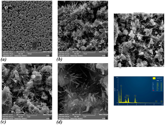
Figure 16.
SEM images of the mortar type M with the following magnifications: (a) 650 x, (b) 5.00 kx, (c) 8.00 kx, and (d) 25.00 kx.
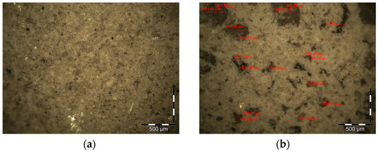
Figure 17.
Optical microscopy technique of mortar type M additions of SAW slag: (a) Surface appearance, (b) Quantitative analysis of failures.
The results presented in Figure 14a, mortar type O with additions of SAW slag, and Figure 16a, mortar type M with SAW slag, with a magnification of SEM MAG 650 x, show that mortar type O presents more flaws, visualised by the considerable number of cracks on the surface, compared to the samples of mortar type M. This result was previously observed using the optical microscopy technique presented in Figure 15a and Figure 17a. Figure 14b and Figure 16b, with SEM MAG 5.00 kx magnification, show that mortars type O doped with SAW slag, are less prone to the formation of crystals from cement hydration, as a consequence of the possible porous formation of the mortar, concerning the mortar type M doped with SAW slag, which is more cohesive and compact, favouring the formation of crystals. The proportions of the mortar with additions of SAW slag directly influence the compaction and porosity of the monolithic, causing a reduction in the grain packing factor, and considerably altering the porosity of the mortar. In other words, the hydration of mortars with additions of SAW slag by generating hydrated phases of CSH, with crystals of Portlandite, ettringite, among others, through the products of the cement’s chemical reactions, directly influences the refinement of the pores. The refinement of the pores is damaged by the large amount of these materials present in the type O mortar mixture, which alters the ability to yield water to the substrate and reduces the adhesion of the mortar to the substrate. In Table 1 it can be seen that type O mortars have lower water/binder ratio values. However, in comparison to type M mortars, these samples have only 46% less water in the system, which demonstrates that the amount of water present in the system and the percussion materials involved are a factor influencing adhesion. The observation of pore refinements through the hydrated phases is reinforced in Figure 14c,d and Figure 16c,d, with SEM MAG magnification 15.0 kx and 30.0 kx, in which it is observed that Type M mortars have more refined pores through the formation of hydrated phase crystals, as described by [50].
In Figure 15a and Figure 17a, the performance of the percussion materials involved is observed, where the proportions used trigger the optimization of the development of hydrated products. For type O mortars we can observe that pores in the monolithic are more pronounced, while for type M mortars, these flaws in the monolithic tend to be mitigated. This finding, in terms of pore refinement, was also observed by [51], when evaluating the development and refinement of pores in mortars with additions of metakaolin, that is, containing mineral additions in its proportions. Furthermore, Figure 15b and Figure 17b show that the average pore size for type O mortars is 276.46 µm, while for type M mortars, the average pore size is 178.32 µm, that is, the increase in the average size of type O mortar in relation to type M is approximately 65%, as observed by [51]. Therefore, we can conclude that mortars with additions of SAW slag, type M, contain proportions of percussive materials, more suitable for mitigating the formation of these pores and that the addition of SAW slag contributes to the formation of hydrated products beneficial to pore refinement, in accordance with [52].
The analysis of the surfaces of mortar samples with additions of SAW slag (type O and M), using the scanning of a certain area with the application of X-rays and detection by the EDS detector to obtain compositional maps (see Figure 18 and Figure 19), showed the predominance of calcium, silicon, and oxygen. It is possible to observe that the proportions of calcium and silicon in type O mortars are much higher than those observed in type M mortars, which is in accordance with the proportions used in the mixtures to manufacture the mortars. These Figures also show, on the surface of the samples, the main chemical elements (Ca, Si, Al, Fe) present in the cement phases, raising the hypothesis that these elements may interact through chemical bonds with other contact surfaces.
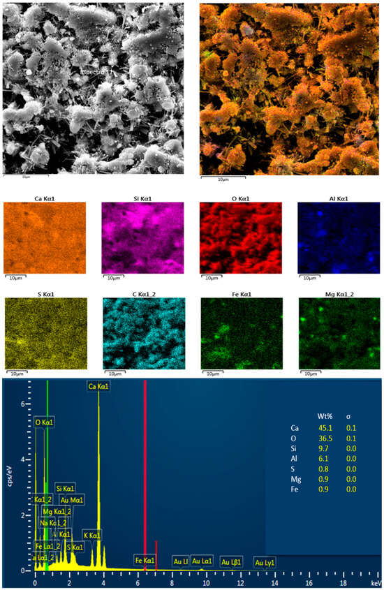
Figure 18.
Compositional map of mortar type O.
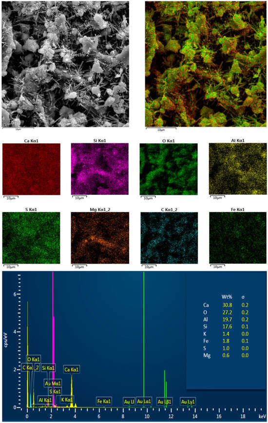
Figure 19.
Compositional map of mortar type M.
The results presented in Figure 18 and Figure 19, which show the predominant chemical elements in Portland cement, are quite coherent, in terms of the proportions of the materials used in mortars type O and M. On the other hand, it is possible to observe that mortar type O presents a higher amount of Ca and Si (see Figure 18) compared to the mortar type M presented in Figure 19, i.e., the concentration of these elements (Ca and Si) among others are changed. Figure 18 (mortar type O) also shows that the predominant chemical elements are calcium, oxygen, and silicon, instead in mortar type M the predominant chemical elements are aluminium and calcium (see Figure 19), but there is a small concentration of other elements on the surface such as silicon, which leads us to believe that on the surface of the mortar type M there are a greater compositional distribution, in terms of different chemical elements, thus having a greater possibility of chemical interactions on the surface.
Moreover, the significant amount of aluminium presented in mortar type M, enables the hypothesis of the existence of an interaction of hydration-forming phases beneficial to the mechanical performance of the sample, i.e., there is an interaction of the aluminium with portlandite and silica, forming the secondary CSH phase, which corroborates the results presented by [49]. This hypothesis justifies the slight decrease of calcium on the surface of the sample (see Figure 19), associated with the proportions of the materials used in the mixture, compared to the result of the compositional map of the mortar type O (see Figure 18). In addition, the increase in the adhesion strength tensile values observed in Figure 2 shows that mortars with additions of SAW slug, for all mixtures analysed, must be forming secondary CSH phases; a similar result was observed by [53]. The beneficial phenomenon related to the effects of the interactions of Portlandite with aluminates, forming and increasing the secondary CSH phase in the mixtures, is already known in the literature and widely discussed, namely with the mineral additions of metakaolin [51,52,53,54,55]. In summary, it is a very credible hypothesis that mortars with additions of SAW slag present better mechanical performance due to the effect of calcium, silicon, and oxygen concentrations on the surface, especially in the case of substrates prepared with spatter dash.
4. Conclusions
In this work, the effects of the mixing water loss capacity of hydrated lime mortars with different dosages and with additions of SAW slag were analysed. Given the results analysed and presented, the main conclusions are:
- -
- The mortar samples with additions of SAW slag showed excellent performance, superior to that established in the adhesion resistance tests of the standard [16].
- -
- The substrate preparation with a spatter dash layer increases the adhesion of the mortar to the substrate.
- -
- The spatter dash layer (without hydrated lime and with lower proportions of sand) increases the capacity to transfer water to the substrate, as observed in thermographic analyses, causing refinement of the substrate pores and better anchoring.
- -
- This finding is reinforced by the fact of the transport, through water, of ions of calcium, silicon, iron, aluminium, magnesium, and potassium, among others, present in cement and in particular the ions present on the surface of mortars that are transported and stored in the pores of the substrates.
- -
- The water-yielding capacity of the mortar with additions of SAW slag to the substrate and the phenomenon of adhesion are directly related to the amount of hydrated lime and sand present in the system, as well as the preparation of the substrate with a spatter dash layer.
- -
- The capacity to retain mixing water in mortars is associated with the amount of hydrated lime presents in the system.
- -
- The ability to transfer water to the substrate is impaired and directly affects the anchorage of the mortar and consequently the adhesion strength, as all mortar samples of type O, with more hydrated lime, showed worse adhesion results. Moreover, as the amount of hydrated lime was reduced in the samples tested, the adhesion strength increased.
- -
- The proportions of sand in the system influence the water retention capacity of the mortar system and anchorages due to their volumetric defects as, by storing water and reducing the transport of cement sedimentary particles to the pores of the substrate through leaching, the anchoring process and adhesion strength are negatively influenced.
In summary, the mortar samples with additions of SAW slag type M, using low-cost materials, proved to be in economic and technical terms (adhesion strength) the best solution, even more so if a spatter dash layer is used—a fact that increases the adhesion strength even more. Moreover, it will be possible to simulate these results in future research, evaluating aspects of the excellent potential to be used as aggregates in the reinforcement of the base and sub-base for paving associated with flexural strength assessment.
Author Contributions
Conceptualization, É.S., A.S., M.M. and R.B.; methodology, É.S., A.S., M.M. and R.B.; software, É.S., A.S., M.M. and R.B.; validation, É.S., A.S., M.M., J.M.P.Q.D. and R.B.; formal analysis, É.S., A.S., M.M., J.M.P.Q.D. and R.B.; investigation, É.S., A.S., M.M. and R.B.; data writing—original draft preparation, É.S., A.S., M.M., J.M.P.Q.D. and R.B.; writing—review and editing, É.S., A.S., M.M., J.M.P.Q.D. and R.B.; visualization, É.S., A.S., M.M., J.M.P.Q.D. and R.B.; supervision, R.B.; funding acquisition, J.M.P.Q.D. and R.B. All authors have read and agreed to the published version of the manuscript.
Funding
This work was financially supported by national funds through the FCT/MCTES (PIDDAC), under the project 2022. 06841.PTDC—BlueHouseSim—Development of numerical simulation tools and methodologies for high-efficiency off-the-electrical-grid houses, with a DOI: 10.54499/2022.06841.PTDC (https://doi.org/10.54499/2022.06841.PTDC). In addition, this work was financially supported by Base Funding—UIDB/04708/2020, with a DOI: 10.54499/UIDB/04708/2020 (https://doi.org/10.54499/UIDB/04708/2020); Programmatic Funding—UIDP/04708/2020, with a DOI: 10.54499/UIDP/04708/2020 (https://doi.org/10.54499/UIDP/04708/2020) of the CONSTRUCT funded by national funds through the FCT/MCTES (PIDDAC); and FCT through the individual Scientific Employment Stimulus 2020.00828.CEECIND/CP1590/CT0004—DOI: 10.54499/2020.00828.CEECIND/CP1590/CT0004 (https://doi.org/10.54499/2020.00828.CEECIND/CP1590/CT0004). Moreover, this research was funded by the Brazilian Agencies FACEPE (APQ-1089-3.01/24), CAPES and CNPq.
Data Availability Statement
The data that support the findings of this study are available upon request from the authors.
Acknowledgments
The authors also thank the Federal University of Paraiba, the University of Pernambuco, and the Federal University of Pernambuco, for the availability of equipment.
Conflicts of Interest
The authors declare no conflicts of interest.
References
- Mendonça, S.V.S. Welding Support from Geopolymerization of Slag Welding Flux. Master’s Thesis, Universidade Estadual do Norte Fluminense, Rio de Janeiro, Brazil, 2017. (In Portuguese). [Google Scholar]
- Nimker, D.; Wattal, R. Recycling of submerged arc welding slag for sustainability. Prod. Manuf. Res. 2020, 8, 182–195. [Google Scholar] [CrossRef]
- Jindal, S.; Singh, H. Optimization of recycled slag-fresh flux mixture based upon weld bead quality for submerged arc welding of stainless steel. J. Mech. Behav. Mater. 2021, 30, 9–18. [Google Scholar] [CrossRef]
- Garg, J.; Singh, K. Slag recycling in submerged arc welding and its effects on the quality of stainless-steel claddings. Mater. Des. 2016, 108, 689–698. [Google Scholar] [CrossRef]
- Apolônio, P.H.; Mota, J.M.F.; Barbosa, F.R.; Silva, A.J.C.E.; Silva, G.A.; Oliveira, R.A. Análise comparativa da resistência de aderência do chapisco com diferentes relações água-ligante e adição de metacaulim. In Proceedings of the Simpósio Brasileiro de Tecnologia das Argamassas, Porto Alegre, Brazil, 28–30 April 2015; pp. 1–13. (In Portuguese). [Google Scholar]
- Maranhão, F.L.; Loh, K.; John, V.M. The influence of moisture on the deformability of cement-polymer adhesive mortar. Constr. Build. Mater. 2011, 25, 2948–2954. [Google Scholar] [CrossRef]
- Pino, F.; Fermo, P.; La Russa, M.; Ruffolo, S.; Comite, V.; Baghdachi, J.; Pecchioni, E.; Fratini, F.; Cappelletti, G. Advanced mortar coatings for cultural heritage protection. Durability towards prolonged UV and outdoor exposure. Environ. Sci. Pollut. Res. 2017, 24, 12608–12617. [Google Scholar] [CrossRef]
- Barberousse, H.; Ruot, B.; Yéprémian, C.; Boulon, G. An assessment of façade coatings against colonisation by aerial algae and cyanobacteria. Build. Environ. 2007, 42, 2555–2561. [Google Scholar] [CrossRef]
- Paiva, H.; Esteves, L.P.; Cachim, P.B.; Ferreira, V.M. Rheology and hardened properties of single-coat render mortars with different types of water retaining agents. Constr. Build. Mater. 2009, 23, 1141–1146. [Google Scholar] [CrossRef]
- Spósito, F.A.; Higuti, R.T.; Tashima, M.M.; Akasaki, J.L.; Melges, J.L.P.; Assunção, C.C.; Bortoletto, M.; Silva, R.G.; Fioriti, C.F. Incorporation of PET wastes in rendering mortars based on Portland cement/hydrated lime. J. Build. Eng. 2020, 32, 101506. [Google Scholar] [CrossRef]
- Ramos, M.C.; Barbosa, J.A. Basic Unit Cost Simulation from Free-Stall Design To Dairy Cattle Confinement Using Different Construction Techniques. Eng. Agrícola 2016, 36, 972–983. [Google Scholar] [CrossRef][Green Version]
- Botas, S.; Veiga, R.; Velosa, A. Bond strength in mortar/ceramic tile interface—Testing procedure and adequacy evaluation. Mater. Struct. 2017, 50, 211. [Google Scholar] [CrossRef]
- Santos, C.; Rocha, J.; Póvoas, Y. Use of infrared thermography for detection of moisture sources in internal walls of buildings. Ambient. Constr. 2019, 19, 105–127. [Google Scholar] [CrossRef]
- NBR 7200; Render Made of Inorganic Mortars Applied on Walls and Ceilings-Procedure for Application. Brazilian Association of Technical Standards: Rio de Janeiro, Brazil, 1998.
- Hossain, M.M.; Karim, M.R.; Hasan, M.; Hossain, M.K.; Zain, M.F.M. Durability of mortar and concrete made up of pozzolans as a partial replacement of cement: A review. Constr. Build. Mater. 2016, 116, 128–140. [Google Scholar] [CrossRef]
- Li, M.; Zhu, X.; Mukherjee, A.; Huang, M.; Achal, V. Biomineralization in metakaolin modified cement mortar to improve its strength with lowered cement content. J. Hazard. Mater. 2017, 329, 178–184. [Google Scholar] [CrossRef] [PubMed]
- Shu, X.; Graham, R.K.; Huang, B.; Burdette, E.G. Hybrid effects of carbon fibers on mechanical properties of Portland cement mortar. Mater. Des. 2015, 65, 1222–1228. [Google Scholar] [CrossRef]
- Ince, C.; Derogar, S.; Ball, R.J.; Ekinci, A.; Yuzer, N. Long-term mechanical properties of cellulose fibre-reinforced cement mortar with diatomite. Adv. Cem. Res. 2018, 31, 342–353. [Google Scholar] [CrossRef]
- Ramakrishna, G.; Priyadharshini, S. Effect of embedment length of untreated natural fibres on the bond behaviour in cement mortar. Front. Struct. Civ. Eng. 2018, 12, 454–460. [Google Scholar] [CrossRef]
- Zhang, B.; Tan, H.; Shen, W.; Xu, G.; Ma, B.; Ji, X. Nano-silica and silica fume modified cement mortar used as Surface Protection Material to enhance the impermeability. Cem. Concr. Compos. 2018, 92, 7–17. [Google Scholar] [CrossRef]
- Lu, J.X.; Poon, C.S. Use of waste glass in alkali-activated cement mortar. Constr. Build. Mater. 2018, 160, 399–407. [Google Scholar] [CrossRef]
- Chaidachatorn, K.; Suebsuk, J.; Horpibulsuk, S.; Arulrajah, A. Extended water/cement ratio law for cement mortar containing recycled asphalt pavement. Constr. Build. Mater. 2019, 196, 457–467. [Google Scholar] [CrossRef]
- Al-Tulaian, B.S.; Al-Shannag, M.J.; Al-Hozaimy, A.R. Recycled plastic waste fibers for reinforcing Portland cement mortar. Constr. Build. Mater. 2016, 127, 102–110. [Google Scholar] [CrossRef]
- Zhang, J.; Shi, C.; Li, Y.; Pan, X.; Poon, C.S.; Xie, Z. Influence of carbonated recycled concrete aggregate on properties of cement mortar. Constr. Build. Mater. 2015, 98, 1–7. [Google Scholar] [CrossRef]
- Carasek, H.; Araújo, R.C.; Cascudo, O.; Angelim, R. Parâmetros da areia que influenciam a consistência e a densidade de massa das argamassas de revestimento. Matéria 2016, 21, 714–732. [Google Scholar] [CrossRef]
- NBR 7175; Hydrated Lime for Mortars—Requirements. Brazilian Association of Technical Standards: Rio de Janeiro, Brazil, 2003.
- De Moura, M.V.; Paiva, S.A.; Rodrigues, V.D.; Felipe, T.; Santos, D.A.; Berenguer, R.A. Analysis of the influence of mechanical properties of cementitious composites using submerged arc welding (SAW) slag recycled aggregate. Revista Gestão Secretariado 2024, 15, e3623. [Google Scholar] [CrossRef]
- NBR 13276; Mortars Applied on Walls and Ceilings—Determination of the Consistence Index. Brazilian Association of Technical Standards: Rio de Janeiro, Brazil, 2016.
- NBR 13749; Render Made of Inorganic Mortar Walls and Ceillings Applications—Specification. Brazilian Association of Technical Standards: Rio de Janeiro, Brazil, 2013.
- ASTM C618; Standard Specification for Coal Fly Ash and Raw or Calcined Natural Pozzolan for Use in Concrete. American Society for Testing and Materials: West Conshohocken, PA, USA, 2017.
- NBR 12653; Pozzolanic Materials—Requirements. Brazilian Association of Technical Standards: Rio de Janeiro, Brazil, 2015.
- Pachta, V.; Serpezoudi, C.; Stefanidou, M. The influence of pre-wetting with consolidants on the adhesion of double-layer lime based mortars. J. Cult. Herit. 2020, 46, 21–30. [Google Scholar] [CrossRef]
- dos Santos, A.R.L.; da Silva Veiga, M.D.R.; dos Santos Silva, A.M.; de Brito, J.M.C.L. Tensile bond strength of lime-based mortars: The role of the microstructure on their performance assessed by a new non-standard test method. J. Build. Eng. 2020, 29, 21–30. [Google Scholar] [CrossRef]
- Almeida, J.A.P.P.; Pereira, E.B.; Barros, J.A.O. Assessment of overlay masonry strengthening system under in-plane monotonic and cyclic loading using the diagonal tensile test. Constr. Build. Mater. 2015, 94, 851–865. [Google Scholar] [CrossRef]
- Carasek, H.; Japiassú, P.; Cascudo, O.; Velosa, A. Bond between 19th Century lime mortars and glazed ceramic tiles. Constr. Build. Mater. 2014, 59, 85–98. [Google Scholar] [CrossRef]
- Huang, Y.; Shih, P.; Hsu, K.T.; Chiang, C.H. To identify the defects illustrated on building facades by employing infrared thermography under shadow. NDT E Int. 2020, 111, 102240. [Google Scholar] [CrossRef]
- Dong, L.; Wang, B.; Wang, H.; Xiang, M.; Chen, X.; Ma, G.; Di, Y.; Guo, W.; Kang, J.; Zhou, X. Effects of crack surface roughness on crack heat generation characteristics of ultrasonic infrared thermography. Infrared Phys. Technol. 2020, 106, 103262. [Google Scholar] [CrossRef]
- Rani, M.F.H.; Razlan, Z.M.; Shahriman, A.B.; Ibrahim, Z.; Wan, W.K. Comparative study of surface temperature of lithium-ion polymer cells at different discharging rates by infrared thermography and thermocouple. Int. J. Heat Mass Transf. 2021, 153, 119595. [Google Scholar] [CrossRef]
- Al-Habaibeh, A.; Sen, A.; Chilton, J. Evaluation Tool for The Thermal Performance of Retrofitted Buildings Using an Integrated Approach of Deep Learning Artificial Neural Networks and Infrared Thermography. Energy Built Environ. 2021, 4, 345–365. [Google Scholar] [CrossRef]
- Rocha, J.H.A.; Santos, C.F.; Póvoas, Y.V. Evaluation of the infrared thermography technique for capillarity moisture detection in buildings. Procedia Struct. Integr. 2018, 11, 107–113. [Google Scholar] [CrossRef]
- Miranda, L.F.R.; Selmo, S.M.S. CDW recycled aggregate renderings: Part I—Analysis of the effect of materials finer than 75 μm on mortar properties. Constr. Build. Mater. 2006, 20, 615–624. [Google Scholar] [CrossRef]
- Hendrickx, R.; Roels, S.; Van Balen, K. Measuring the water capacity and transfer properties of fresh mortar. Cem. Concr. Res. 2010, 40, 1650–1655. [Google Scholar] [CrossRef]
- Hall, C.; Tse, T.K.M. Water movement in porous building materials-VII. The sorptivity of mortars. Build. Environ. 1986, 21, 113–118. [Google Scholar] [CrossRef]
- Liu, C.; Qian, R.; Liu, Z.; Liu, G.; Zhang, Y. Multi-scale modelling of thermal conductivity of phase change material/recycled cement paste incorporated cement-based composite material. Mater. Des. 2020, 191, 108646. [Google Scholar] [CrossRef]
- Ke, X.; Bernal, S.A.; Provis, J.L.; Lothenbach, B. Thermodynamic modelling of phase evolution in alkali-activated slag cements exposed to carbon dioxide. Cem. Concr. Res. 2020, 136, 106158. [Google Scholar] [CrossRef]
- Borštnar, M.; Daneu, N.; Dolenec, S. Phase development and hydration kinetics of belite-calcium sulfoaluminate cements at different curing temperatures. Ceram. Int. 2020, 46, 29421–29428. [Google Scholar] [CrossRef]
- Singh, K.; Pandey, S. Recycling of slag to act as a flux in submerged arc welding. Resour. Conserv. Recycl. 2009, 53, 552–558. [Google Scholar] [CrossRef]
- Jiang, C.; Fang, J.; Chen, J.Y.; Gu, X.L. Modeling the instantaneous phase composition of cement pastes under elevated temperatures. Cem. Concr. Res. 2020, 130, 105987. [Google Scholar] [CrossRef]
- Rocha, J.H.A.; Toledo Filho, R.D. Microstructure, hydration process, and compressive strength assessment of ternary mixtures containing Portland cement, recycled concrete powder, and metakaolin. J. Clean. Prod. 2024, 434, 140085. [Google Scholar] [CrossRef]
- Angulo, S.C.; Carrijo, P.M.; Figueiredo, A.D.; Chaves, A.P.; John, V.M. On the classification of mixed construction and demolition waste aggregate by porosity and its impact on the mechanical performance of concrete. Mater. Struct. Constr. 2010, 43, 519–528. [Google Scholar] [CrossRef]
- Zunino, F.; Scrivener, K. The reaction between metakaolin and limestone and its effect in porosity refinement and mechanical properties. Cem. Concr. Res. 2021, 140, 106307. [Google Scholar] [CrossRef]
- Sui, S.; Shan, Y.; Li, S.; Geng, Y.; Wang, F.; Liu, Z.; Jiang, J.; Wang, L.; Yang, Z. Investigation on chloride migration behavior of metakaolin-quartz-limestone blended cementitious materials with electrochemical impedance spectroscopy method. Case Stud. Constr. Mater. 2024, 20, e03064. [Google Scholar] [CrossRef]
- Brekailo, F.; Pereira, E.; Pereira, E.; Filho, J.H.; De Medeiros, M.H.F. Evaluation of the reactive potential of additions of red ceramic waste and comminuted concrete of CDW in cement matrix. Ceramica 2019, 65, 351–358. [Google Scholar] [CrossRef]
- Basto, P.A.; Junior, H.S.; Neto, A.A.M. Characterization and pozzolanic properties of sewage sludge ashes (SSA) by electrical conductivity. Cem. Concr. Compos. 2019, 104, 103410. [Google Scholar] [CrossRef]
- Zhang, X.; Bai, Y.; Luo, Q. Exploring synergistic effects and hydration mechanisms in metakaolin-blended cement system with varying metakaolin and wollastonite content. Constr. Build. Mater. 2024, 425, 135962. [Google Scholar] [CrossRef]
Disclaimer/Publisher’s Note: The statements, opinions and data contained in all publications are solely those of the individual author(s) and contributor(s) and not of MDPI and/or the editor(s). MDPI and/or the editor(s) disclaim responsibility for any injury to people or property resulting from any ideas, methods, instructions or products referred to in the content. |
© 2024 by the authors. Licensee MDPI, Basel, Switzerland. This article is an open access article distributed under the terms and conditions of the Creative Commons Attribution (CC BY) license (https://creativecommons.org/licenses/by/4.0/).