Article

Experimental Study on the Mechanical Properties of Steel Fiber Ferronickel Slag Powder Concrete

1
Shengsi County Urban and Rural Construction Investment and Development Co., Ltd., 349 Shahe Rd, Shengsi, Zhoushan 202450, China
2
National Engineering Laboratory for Applied Technology of Forestry & Ecology in South China, Central South University of Forestry and Technology, 498 South Shaoshan Rd, Changsha 410075, China
3
Institute of Structural Material Failure and Strengthening Technology, Ningbo Polytechnic, 388 East Lushan Rd, Ningbo 315800, China
4
School of Architectural Engineering, Hunan Institute of Engineering, Xiangtan 411100, China
*
Author to whom correspondence should be addressed.
Buildings 2024, 14(8), 2471; https://doi.org/10.3390/buildings14082471
Submission received: 28 May 2024 / Revised: 25 June 2024 / Accepted: 7 August 2024 / Published: 10 August 2024
(This article belongs to the Section Building Materials, and Repair & Renovation)

Abstract

The use of ferronickel slag powder (FNSP) as a cementitious additional material has been supported by numerous reports. FNSP concrete has the same shortcomings as ordinary concrete, including low hardness. In this study, in order to make FNSP concrete more durable, end-hooked type steel fibers were incorporated. To understand how various elements affect the mechanical properties of steel fibers, an experiment was carried out on the mechanical properties of steel FNSP concrete (SFNSPC). FNSP’s principal ingredients, with a particle size distribution ranging from 0.5 to 100 μm and a sheet-like powder shape, are CaO, SiO2, Al2O3, MgO, and others, according to tests conducted on the material’s microstructure and composition. Then, eighteen mix proportions were developed, comprising six distinct FNSP replacement rate types and three distinct steel fiber content types. Crucial metrics were evaluated and analyzed, including the relationship among the toughness, tensile strength, and compressive strength as well as slump, splitting tensile strength, compressive strength, and uniaxial compressive stress–strain curve of SFNSPC. The results showed that the slump of SFNSPC under different FNSP replacement rates decreased with increasing steel fiber volume. Steel fibers have a small but positive effect on SFNSPC’s compressive strength; nonetheless, as FNSP replacement rates increased, SFNSPC’s slump gradually decreased, though not by much. These results show that FNSP is a viable alternative cementitious material in terms of strength. Specifically, the splitting tensile strength of SFNSPC improves with an increase in steel fiber content, and the pace at which SFNSPC strength drops with an increase in the FNSP replacement rate. With varying mix proportions, the stress–strain curve trend of SFNSPC remains mostly constant, and steel fibers improve the compressive toughness of SFNSPC. After adding 0.5% and 1.0% steel fibers, the toughness index of concrete with different FNSP replacement rates increased by 8–30% and 12–43%, respectively.

1. Introduction

Energy conservation and emission reduction are issues that need to be taken seriously in the construction of infrastructure such as building structures. At present, the research on green building materials mainly includes two aspects; one is the use of waste solids such as recycled aggregate or waste ceramic instead of concrete aggregate [1], and the other is the use of slag powder or other powder such as waste marble powder [2] instead of cement.
The production process of cement requires a large amount of energy consumption and is one of the three major carbon-emitting industries in China. Therefore, scholars and the engineering community have proposed the use of low-carbon construction materials. Among them, there has been a lot of research and application on replacing cement with slag powder. Slag is also a type of waste, and using it as a construction material can achieve two goals with one stone.
Nickelite is one of the major mines, and the amount of ferronickel slag (FNS) is also large. The main components of FNS are CaO, SiO2, Al2O3, MgO, etc., which, similar to Metakaolin and other auxiliary cementitious materials, have the potential to become auxiliary cementitious materials. Using FNS as a construction material can play a role in waste utilization and contribute to carbon emissions [3]. Many scholars have conducted research on the application of FNS in concrete materials. FNS concrete can save USD 10/t in materials, in addition to reducing carbon emissions by 4–24% [4]. The application research of FNS in concrete mainly includes two aspects. The first is adding FNS as fine aggregate into concrete, and the second is grinding FNS into powder as a cementitious auxiliary material and adding it into concrete.
Sun et al. [5] prepared concrete by utilizing FNS as fine aggregate rather than sand, and they examined the impact of the FNS fine aggregate on the mechanical characteristics of the concrete. In order to investigate the compressive behavior of recycled concrete mixed with FNS as fine aggregate, Bao et al. [6] created multiple sets of concrete specimens with varying replacement rates of FNS fine aggregate. The coupling effect of FNS and recycled aggregate on the water absorption and chloride ion permeability of concrete was examined, and their compressive strengths were tested. The performance of concrete using fly ash and FNS fine aggregate under the alkaline silica reaction and chloride pollution was investigated by Nguyen et al. [7]. Concrete prism tests, accelerated diffusion tests, and overall diffusion tests were used to examine the induced expansion, chloride ion diffusion resistance, and chloride ion binding ability of FNS fine aggregate concrete. Saha and Sarker [8] used fly ash and FNS fine aggregate to assess the durability properties of concrete. They found that the volume of permeable voids in concrete increased with the amount of FNS fine aggregate. Their findings showed that the adsorption and chloride ion permeability showed an increasing trend with the increase in FNS fine aggregate. The effects of partially substituting FNS fine aggregate for natural sand in high-strength self-compacting concrete were examined by Nuruzzaman et al. [9]. Their findings demonstrated that concrete with up to 40% FNS fine aggregate satisfied the standards’ requirements, as evidenced by the lack of segregation in flow tests and the absence of obstruction in the L-shaped box and V-shaped funnel tests. FNS fine aggregate is denser, bigger, and sharper-shaped than sand. Significant segregation and decreased liquidity were observed when FNS was increased to 60%.
Qi et al. [10] investigated the mechanical properties of concrete containing composite admixtures of FNS powder (FNSP) and blast furnace slag powder with varying contents in relation to using FNS as an auxiliary cementitious material. Based on test results, a stress–strain constitutive was established for this kind of concrete. The impact of FNSP on the performance of geopolymer concrete was primarily related to the type of precursor and activator, according to research results reviewed by Han et al. [11], who also conducted a thorough analysis of the sustainable utilization of FNS. In order to determine which FNSP fineness and replacement degree were most advantageous for usage as a binder, Kim et al. [4] employed FNSP in place of ordinary Portland cement (OPC) in concrete. Tests of FNSP concrete’s mechanical characteristics included compression, bending, shear, and splitting tensile strength evaluations. In order to investigate important physical parameters such as porosity, density, compressive strength, and the permeability coefficient, Tang et al. [12] created eighteen mix proportions of FNSP-OPC permeable concrete. Their outcomes demonstrated that adding FNSP to permeable concrete was a workable application strategy.
Relevant studies on reinforced FNS concrete also show that FNS concrete has great potential. For example, Qi et al. [13] carried out a steel bar pull-out test to study the bonding performance of steel bars in iron-bearing nickel–iron slag concrete. Their results showed that the bonding performance of steel bars in FNS concrete was not as good as that of ordinary concrete even when the strength of concrete was similar. According to the results of the test, the bond stress–slip relationship and anchoring length correction coefficient of C30 and C35 strength grade FNS concrete were proposed so as to improve the applicability of FNS concrete. Liu et al. [14] carried out static load tests and cyclic loading tests of reinforced FNS concrete beams. The ultimate bearing capacity of the FNS concrete members was similar to that of the conventional concrete members, but the FNS concrete specimens had higher ductility. Liu et al. [15] carried out an experimental study on the flexural performance of FNS concrete beams, and their results showed that when the strength of FNS concrete was equal to that of ordinary concrete, the ductility of the FNS concrete beams was similar to that of ordinary concrete beams. FNS concrete can be used in engineering structures regardless of its powder content as long as it meets the design strength requirements.
Concrete has poor toughness and is prone to cracking and exiting work when subjected to stress. Adding fibers, such as steel fibers, polypropylene fibers, glass fibers, etc., to concrete can effectively improve its tensile strength and toughness [16,17,18,19,20,21,22]. Similar to ordinary concrete, FNSP concrete also has the characteristic of poor toughness. This study attempts to add steel fibers to FNSP concrete, called steel fiber FNSP concrete (FFNSPC), and explore its properties. Firstly, the characteristics of FNSP were tested and analyzed; secondly, FNSP was used as an auxiliary cementitious material, and eighteen mix proportions were designed. The slump, compressive strength, splitting tensile strength, and uniaxial compressive stress–strain curves of the steel fiber FNSP concrete were tested, and the relationship among toughness index, tensile strength, and compressive strength was analyzed, as shown in Figure 1.

2. Materials and Methods
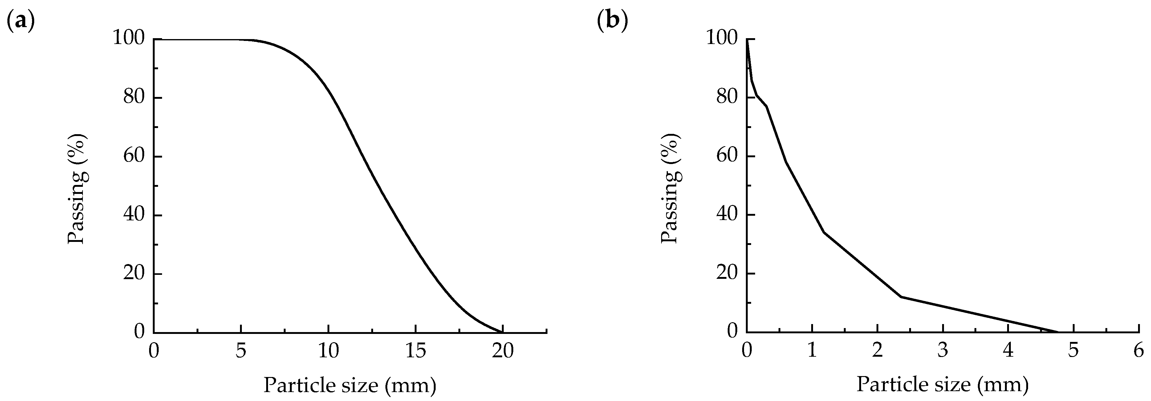
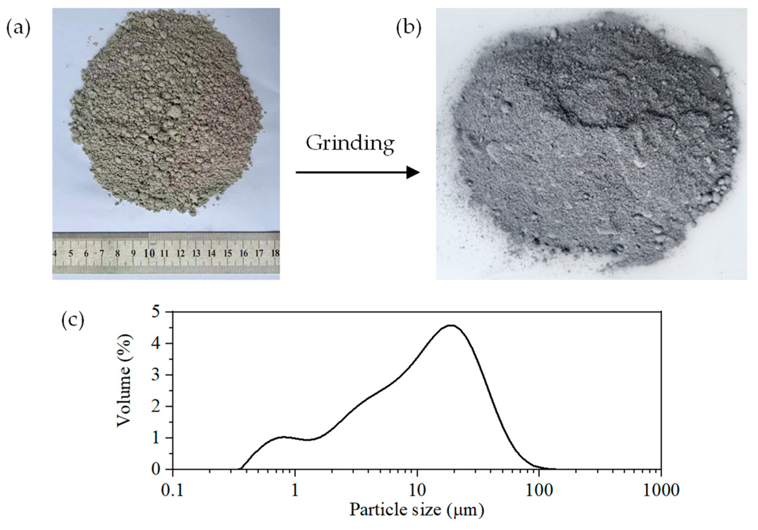
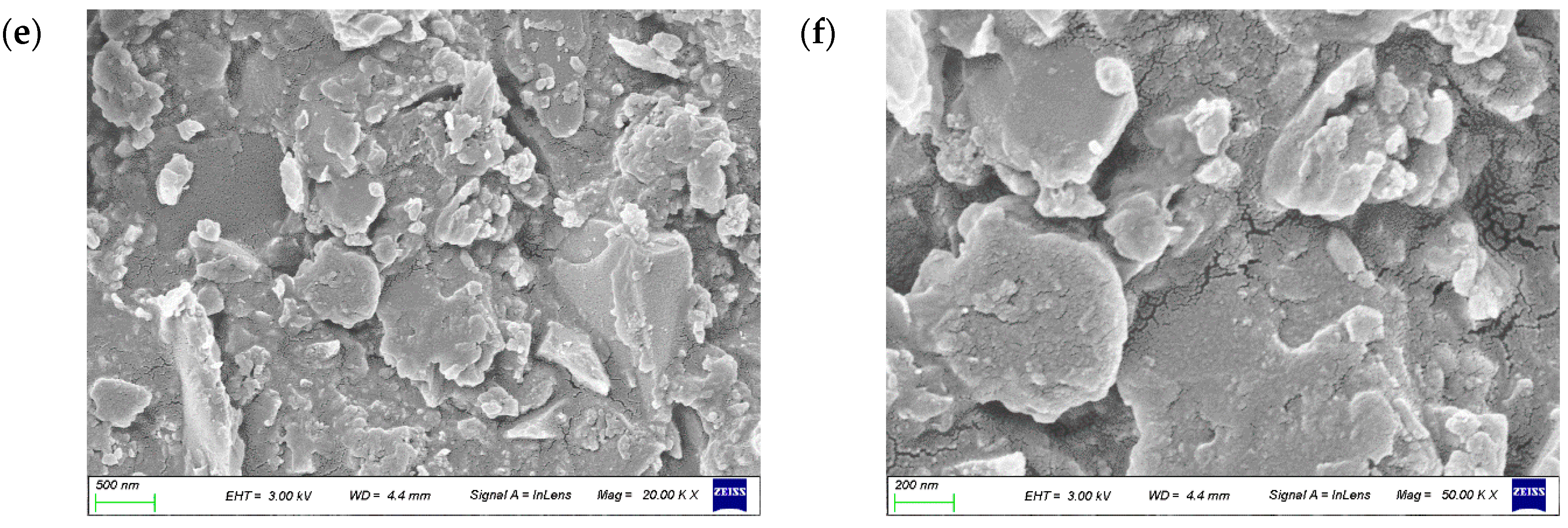
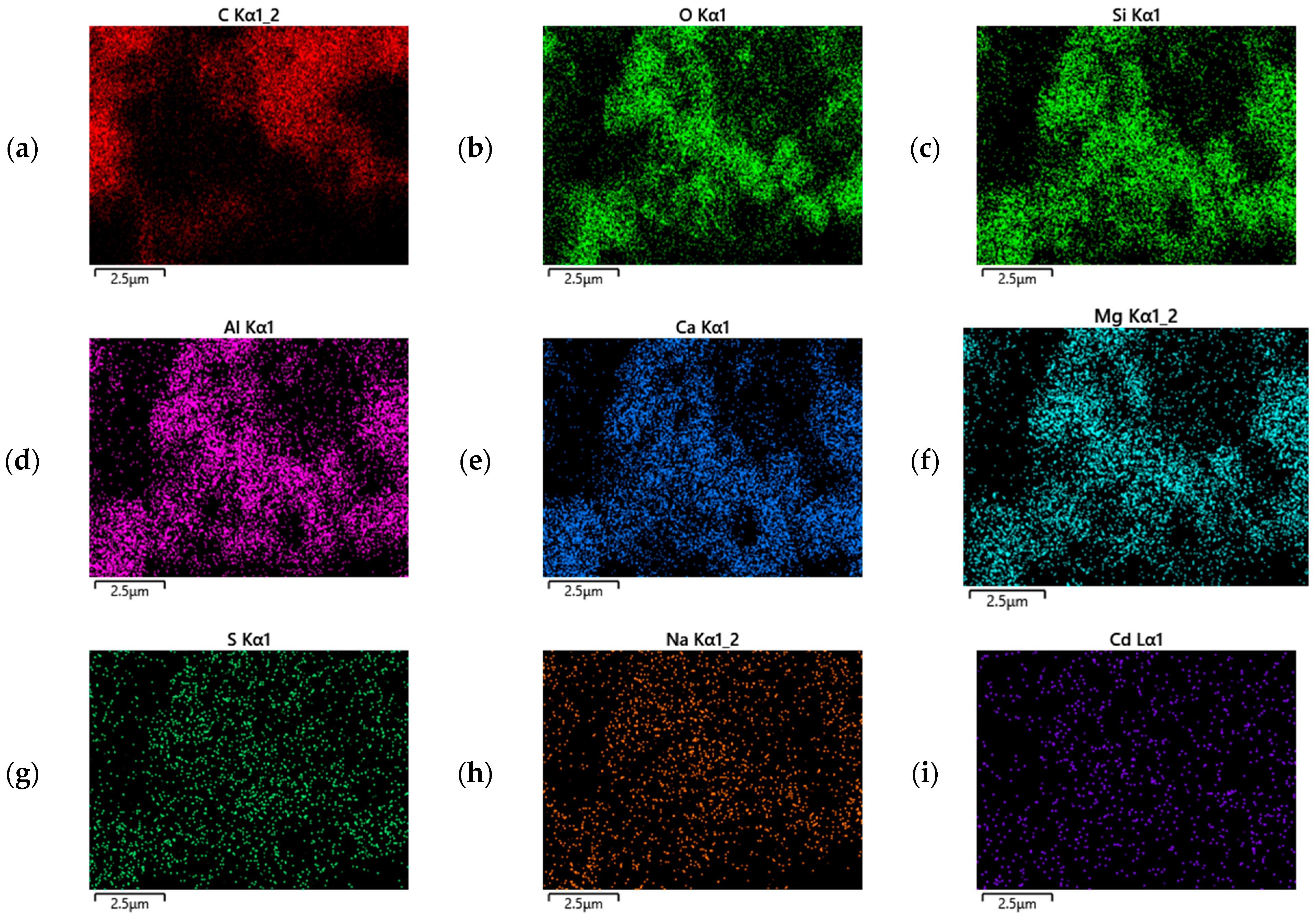
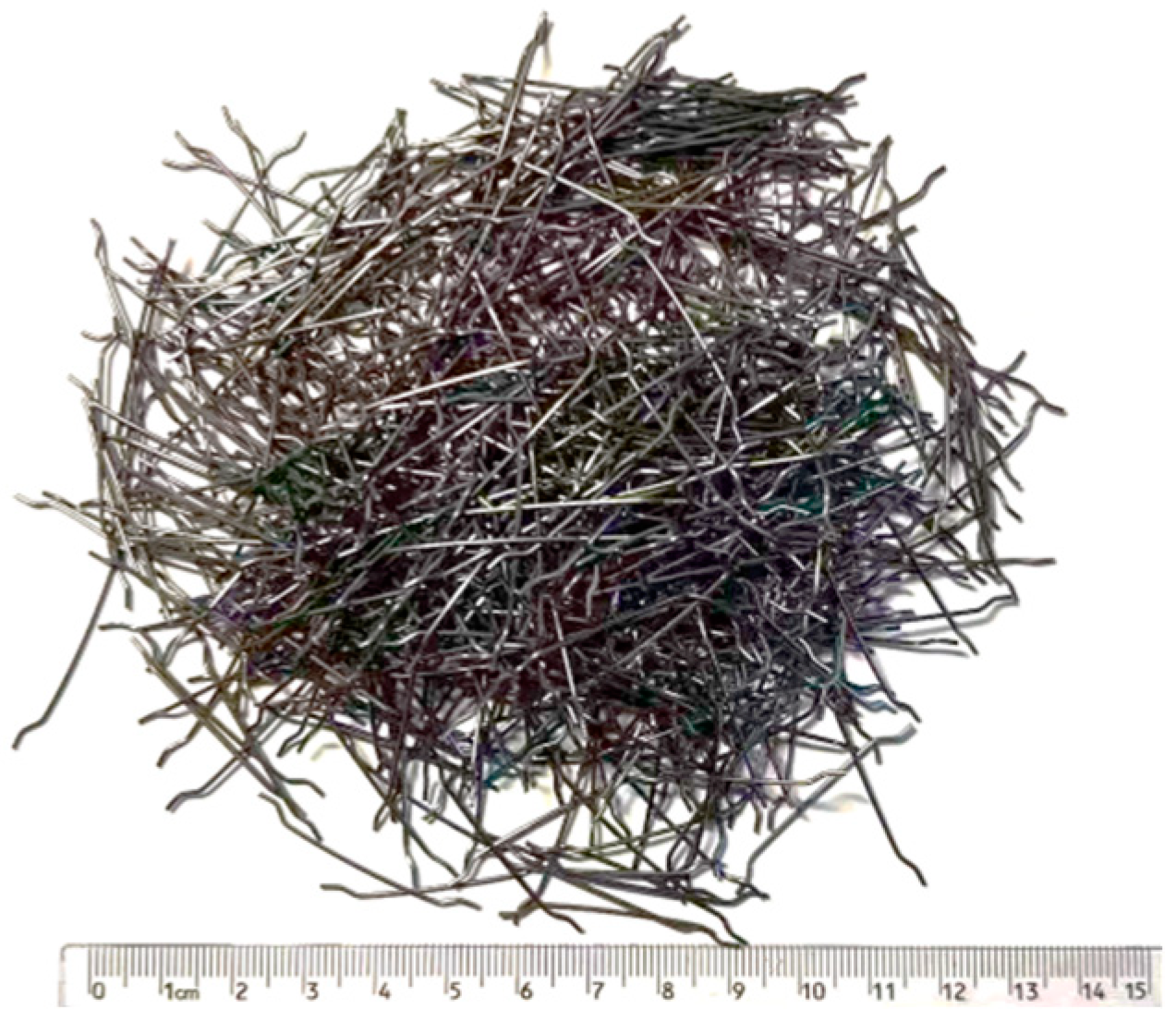
2.1. Raw Materials

The experiment’s primary ingredients included fly ash, cement, FNSP, aggregates, and water. The stones used as coarse aggregate were basalt. The pertinent characteristics of the coarse aggregate used in this experiment were examined in accordance with the guidelines GBT 14684-2011 [23], and the outcomes are displayed in Table 1. Every indicator complied with the specifications. Figure 2a illustrates the coarse aggregate particle size distribution, which is primarily dispersed between 5 and 20 mm.
The manufactured sand served as the fine aggregate. Table 2 displays the results of the fine aggregate performance test conducted in accordance with guideline GBT 14684-2011 [23]. Every indicator complied with the specifications. Figure 2b displays the fine aggregate grading curve.
Ordinary Portland P.O. 42.5 cement was used as the cement (OPC). Figure 3 illustrates FNSP and its particle size distribution, and the grinding process and method of FNSP can be seen in Han et al. [11]. Using a Mastersize 3000 laser particle size analyzer (London, UK), the particle size distribution was determined to be between 0.5 and 100 μm, which gave FNSP the particle size basis needed to become an auxiliary cementitious material. The microstructure of FNSP was examined using a ZEISS Sigma 300 Phenom Pro scanning electron microscopy (SEM) (Oberkochen, German), as depicted in Figure 4. At various magnifications, it was determined that FNSP had a sheet-like morphology. FNSP’s elemental composition was examined using an Oxford Instruments Xplore 30 transmission electron microscope (Oxford, UK); Figure 5 displays the primary elements that were found. In the figure, we set the corresponding color contrast of different elements to show the distribution of elements. The primary elements that made up FNS were C, O, Si, Al, Ca, Mg, S, Na, Cd, N, and so on. The primary constituents of FNSP are listed in Table 3 and include CaO, SiO2, Al2O3, MgO, and other elements; this served as the supplemental cementitious material’s chemical foundation for FNSP [24,25,26,27,28]. In addition, the particle size of FNSP was smaller than that of cement, which made FNSP have higher pozzolanic activity in the late hydration period, and this has also been confirmed by Liu et al. [14].
The steel fiber adopted an end hook type steel fiber, as shown in Figure 6, with a diameter of 0.75 mm and a length of 35 mm. Its length–diameter ratio was 46.67, and its tensile strength was 1120 MPa.

2.2. Mix Proportion

As indicated in Table 4, eighteen mix proportions were created in order to determine the mechanical characteristics of FFNSPC. In mass proportions of 0, 10%, 20%, 30%, 40%, and 50%, FNSP was substituted for OPC. Concrete was mixed with steel fibers proportionate to volume. It should be mentioned that in order to prevent agglomeration, steel fibers must be sprinkled into the concrete gradually. The different types of volume fractions included the following: 0.5%, 1.0%, and 0%. Three 150 mm × 150 mm × 300 mm prism test blocks for uniaxial stress–strain curve testing and six 150 mm cubic test blocks for compressive strength and splitting tensile strength testing for each mix proportion were created.

2.3. Strength Test

Compressive strength testing was carried out utilizing a pressure testing apparatus in compliance with the guideline GB/T 50081-2019 [29]. The final result was determined by averaging the three test results.
The splitting tensile test was used to determine the tensile strength of concrete. The following formula was used to determine the tensile strength of the concrete cube by taking the average of the three test results as the final result. The formula is written as follows,
f t u = 0.637 F A

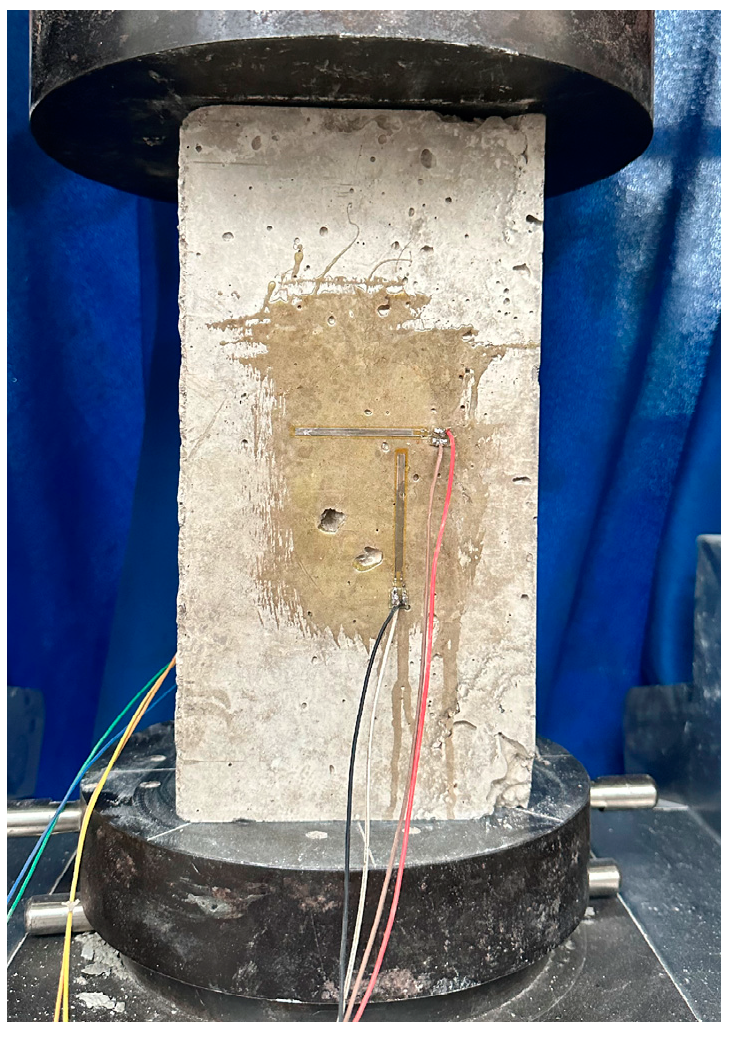
2.4. Stress–Strain Testing

Concrete under uniaxial compression was tested for stress–strain curve conformance to standard GB/T 50081-2019 [29]. Two strain gauges were adhered to one side of the test block in order to measure the strain that developed during the compression operation, as shown in Figure 7.

3. Results and Discussion
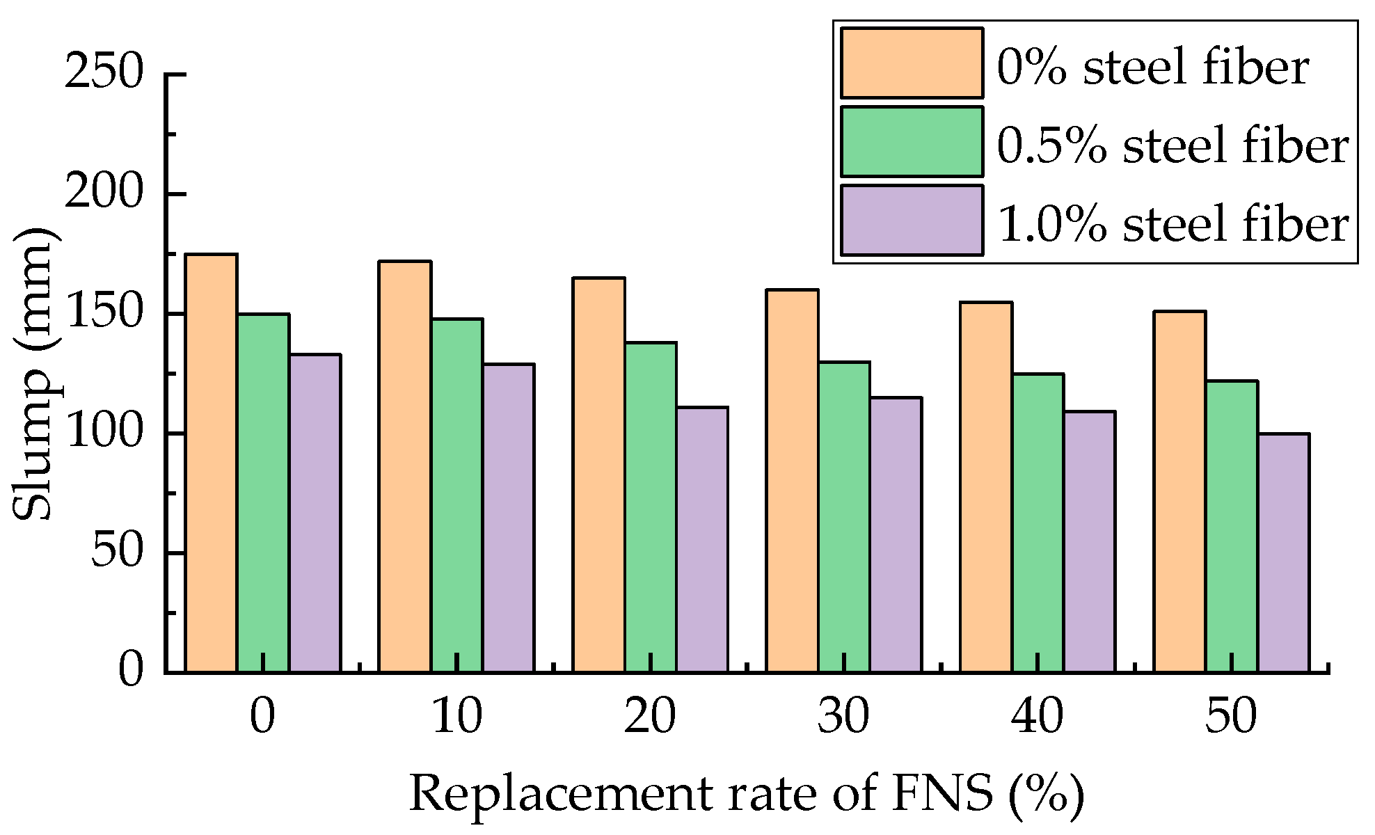
3.1. Slump

Figure 8 depicts SFNSPC’s slump. It is evident that when the volume percent of steel fiber increases, the slump of SFNSPC under various FNSP replacement rates diminishes, essentially exhibiting a linear declining pattern. There is a reduction of 13–19% and 24–34% in the slump as the steel fiber volume fraction rises from 0 to 0.5% and 1.0%, respectively, and this is similar to the results of Zheng et al. [30] (11.1% and 28.3%, respectively).
This suggests that steel fibers significantly affect workability, mostly because of their erratic network structure formed by their random distribution pattern in the concrete mix, which restricts the workability of concrete. In other words, the addition of steel fibers has a negative effect on the workability of concrete, which is similar to other types of steel fiber concrete.
When the volume of steel fibers is 0.5%, the replacement rate of FNSP gradually increases from 0 to 10%, 20%, 30%, 40%, and 50%, and the slump decreases by 1.3%, 8.0%, 13.3%, 16.7%, and 18.9%. When the volume fraction of steel fibers is 1.0%, the replacement rate of FNSP gradually increases from 0 to 10%, 20%, 30%, 40%, and 50%, and the slump decreases by 3.0%, 16.5%, 13.5%, 18.0%, and 24.8%. These findings are based on a comparison of the slump of SFNSPC with different FNSP replacement rates. This analysis was performed for a steel fiber volume fraction of 0%. In general, the slump of SFNSPC decreases with the increase in the replacement rate of FNSP; this is mostly because of FNSP’s sheet-like morphology, which facilitates flocculation and water envelopment and produces comparatively little free water.
Considering the influence of the steel fiber and FNSP replacement rate on concrete slump, the parameter λ f was introduced as follows:
λ f = V f l f d f
where Vf is the volume fraction of steel fibers, lf is the length of the steel fiber, and df is the cross-sectional diameter of the steel fiber.
Compared with ordinary concrete, the addition of steel fibers has a negative effect on slump, while replacing OPC with FNSP has a negative effect. Therefore, a dual parameter fitting model was constructed, and the expression is as follows:
s s 0 = 1 0.60 λ f 0.30 R f
where s denotes the slump of SFNSPC, s0 denotes the slump of concrete without steel fiber and FNSP, and Rf denotes the replacement rate of FNSP. The fitting results are shown in Figure 9, and it can be seen that there is a certain deviation between the fitting results and the ideal results, but overall, the fitting effect is good.

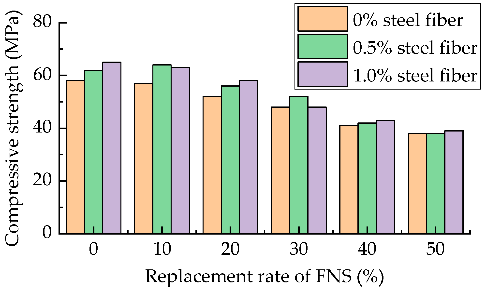
3.2. Compressive Strength

Figure 10 displays the cubic compressive strength of FFNSPC. Overall, it is evident that steel fibers increase the compressive strength of concrete cubes; for example, when the content of FNSP is 0 and the content of steel fiber increases from 0 to 0.5% and 1.0%, the strength of concrete increases by 6.9 and 12.0%. When the FNSP content is 0, the steel fiber content increases from 0 to 0.5% and 1.0%, the concrete strength increases by 7.7% and 11.5%, which are slightly greater than the results obtained by Zheng et al. [30] (4.3% and 9.2%, respectively). However, this effect is not statistically significant, and steel fiber influence on strength may even be negative at varying rates of FNSP replacement. Furthermore, concrete cubes with the same steel fiber content exhibit a loss in compressive strength as the FNSP replacement rate increases; however, this strength reduction is not statistically significant for modest FNSP replacement rates. Figure 11 summarizes the FFNSPC strength decline rate under various FNSP replacement rates. It is evident that when the rate of FNSP replacement rises, so does the rate at which FFNSPC strength is reduced. It is evident by comparing the reference line that the replacement rate—especially at very low replacement rates—is always lower than the strength reduction rate.
For instance, the FFNSPC strength reduction rate ranges from −9% to 10.5% when the replacement rate is 20%, while it is between −3% and 3% when the replacement rate is 10%. This shows that even though some OPC was removed again, the addition of FNSP resulted in increased strength. This is because FNSP contains components like CaO, SiO2, Al2O3, and MgO, which will react hydrolyze with alkaline chemicals in cement and water. Steel fibers do not, however, appear to have any effect on the hydration response of FNSP, as there is no discernible pattern in the effect of varying steel fiber contents on the strength reduction rate.
The addition of steel fibers improved compressive strength as compared with regular concrete; however, FNSP replaced OPC in a negative way. As a result, a dual parameter fitting model was suggested for the component; the expression is displayed below:
f c u f c u , 0 = 1 + 0.35 λ f 0.85 R f
where fcu represents the compressive strength of SFNSPC and fcu,0 is the corresponding strength of ordinary concrete. The fitting results are shown in Figure 12, and it can be seen that there is a certain deviation between the fitting results and the ideal results, but overall, the fitting effect is good.

3.3. Splitting Tensile Strength

Figure 13 depicts SFNSPC’s cubic splitting failure scenario. As can be observed, the splitting tensile failure mode is identical to that of regular concrete reinforced with steel fiber, as shown in Figure 13a,c. Steel fibers with various directions of dispersion can be found in the cracks; the extraction procedure of these steel fibers will act as a “bridging role”, as shown in Figure 13b,d. One can discuss the concrete’s splitting tensile strength, but toughness is also improved since even after cracking, the concrete retains some of its tensile strength and continues to function.
Figure 14 displays the cube splitting tensile strength of SFNSPC. It is evident that the splitting tensile strength of SFNSPC is significantly influenced by steel fibers, as opposed to its compressive strength, and this strength increases as the amount of steel fiber in SFNSPC increases. Under different replacement rates of FNSP, when the steel fiber content increases from 0 to 0.5% and 1.0%, the splitting tensile strength of the concrete increases by about 24% and 58%, respectively, which is similar to the results of Zheng et al. [30] (22.4% and 50.4%, respectively). Furthermore, with an increase in the FNSP replacement rate, the splitting tensile strength of SFNSPC drops with the same steel fiber content; however, this strength reduction is not statistically significant at low FNSP replacement rates.
Figure 15 shows a comparison of the concrete splitting tensile strength reduction rate with various FNSP replacement rates. It is evident that when the rate of FNSP replacement rises, so does the rate at which SFNSPC’s strength is reduced. The rate at which splitting tensile strength decreases is negligible in comparison to compressive strength. When comparing the replacement rate to the strength reduction rate, it is always higher, especially when the replacement rate is low. For example, at a 10% replacement rate, the concrete strength reduction rate is between 1.5% and 2.8%; at a 20% replacement rate, the concrete strength reduction rate is between −4% and 8%.
Compared with ordinary concrete, the addition of steel fibers has a positive effect on compressive strength, while replacing OPC with FNSP has a negative effect. Therefore, a dual parameter fitting model was constructed, and the expression is as follows:
f t u f t u 0 = 1 + 1.20 λ f 0.70 R f
where ftu is the corresponding strength of regular concrete, while ftu,0 is the compressive strength of FFNSPC. Figure 16 displays the fitting results. While there is some variation between the fitting results and the ideal results, the fitting effect is generally good.

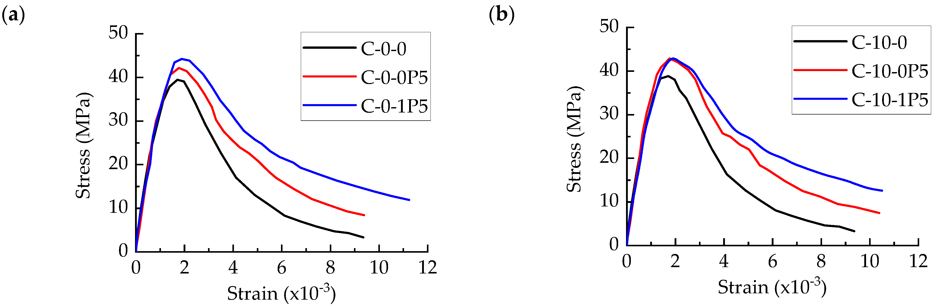
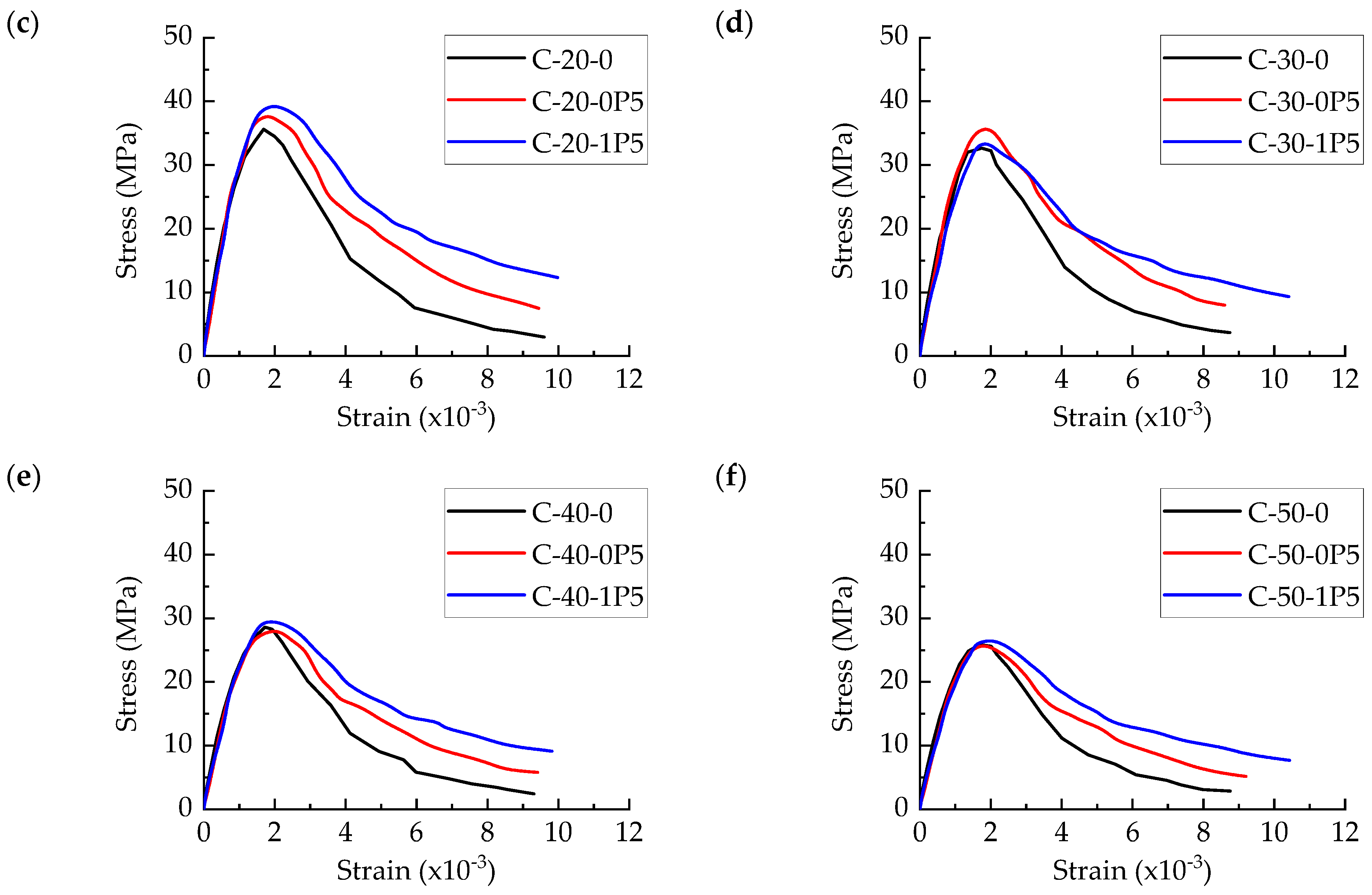
3.4. Compression Stress–Strain Curve

Figure 17 depicts the FFNSPC uniaxial compressive stress–strain curve. As shown, each test block’s stress–strain curve trends are essentially consistent and may be split into two stages as follows: increasing and declining. In the early stages of the rising stage, the fundamental nonlinear properties are not readily apparent. The nonlinear properties are more noticeable in the descending segment, and they become more apparent as the peak stress draws nearer. Tangential stiffness also diminishes as strain increases.
Only the peak stress of the curve is affected by the steel fiber composition; the rising stage of the curve is almost unaffected. Nonetheless, the lowering stage of the curve is significantly influenced by the amount of steel fiber. The curve in the falling stage will be smoother with more steel fiber. That is to say, when the strain rate is the same, the stress value of FFNSPC with more steel fiber is higher, suggesting that steel fiber enhances FFNSPC’s compressive toughness. Other varieties of steel fiber concrete have also demonstrated this relationship [30]. By comparing the stress–strain curves of various FNSP replacement rates, it is possible to determine that the replacement rate of FNSP has very little effect on the trend in the stress–strain curve, with the exception of the curve’s peak stress. Therefore, regular steel fiber-reinforced concrete can be referred to in the FFNSPC uniaxial compressive stress–strain curve.

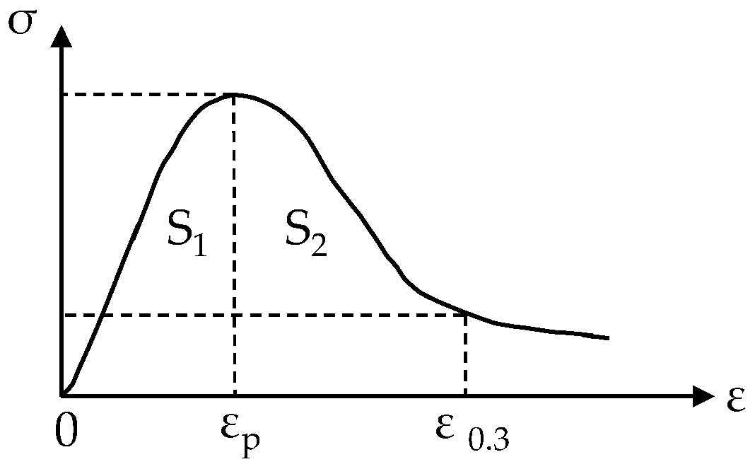
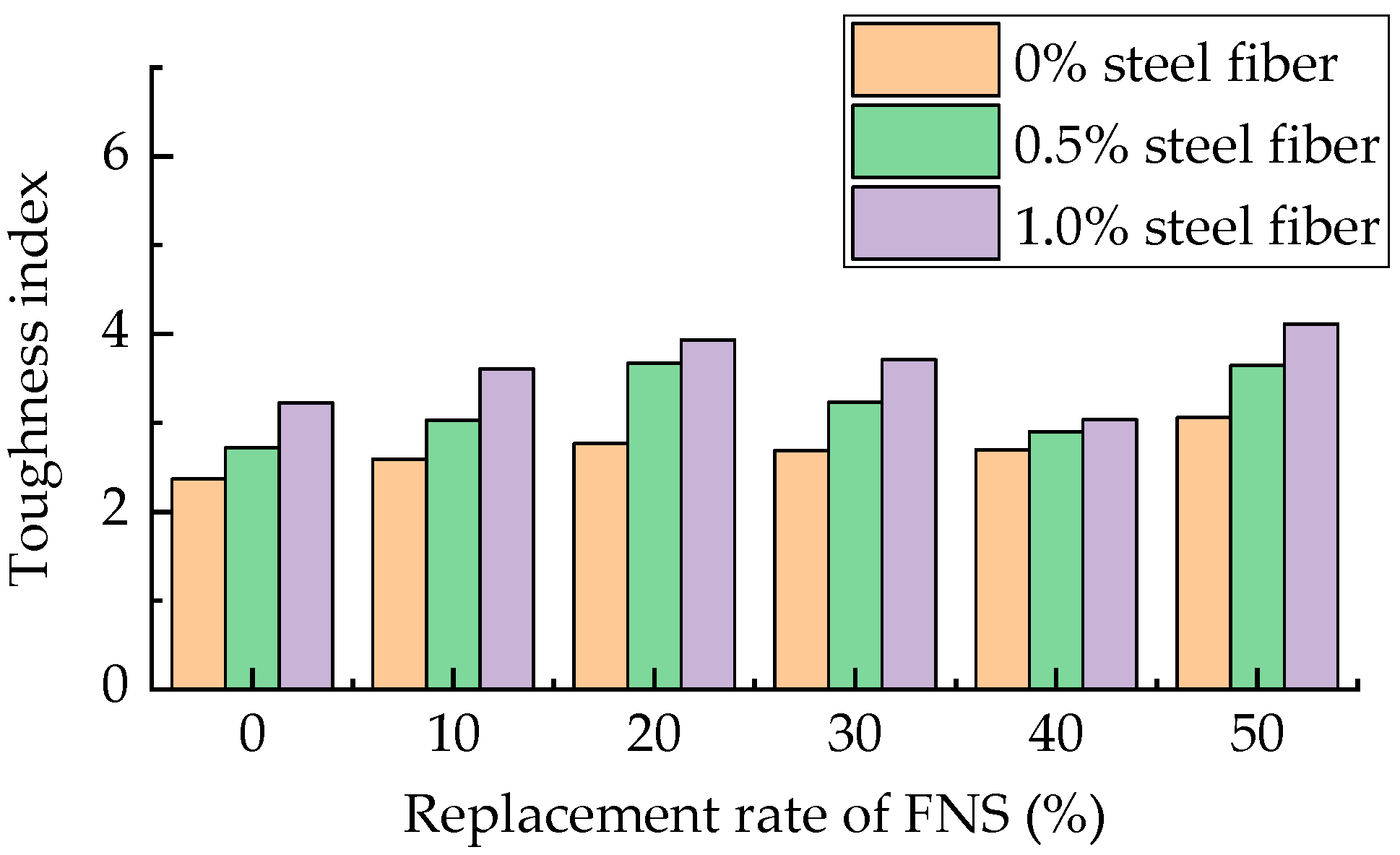
3.5. Toughness Index

The toughness index (TI) of concrete is an important indicator used to evaluate its toughness and deformation ability. The toughness index is the ratio of the area S1 and S2 enclosed by the curve and the abscissa when the stress–strain curve decreases to 30% of the peak load, as shown in Figure 18. S1 and S2 are calculated by Equations (6) and (7), and the expression for TI can be expressed by Equation (8).
S 1 = 0 ε p σ ε d ε
S 2 = ε p ε 0.3 σ ε d ε
T I = S 2 S 1
Figure 19 displays the FFNSPC toughness index derived from the compressive stress–strain curve. As shown, the toughness index is mostly determined by the steel fiber content, and the higher the steel fiber content, the higher the toughness index. Replacement FNSP has no discernible effect on the toughness index. This is mostly because steel fibers were added, allowing the concrete to keep functioning even after it cracked during the compression process. Research on several varieties of steel fiber-reinforced concrete has also demonstrated this result. The addition of 0.5% and 1.0% steel fibers to concrete resulted in increases in its toughness index of 8–30% and 12–43%, respectively, as compared with SFNSPC without steel fibers. This has a greater influence on strength than the quantity of steel fiber added, indicating that while steel fiber has little impact on increasing concrete strength, it significantly increases toughness.

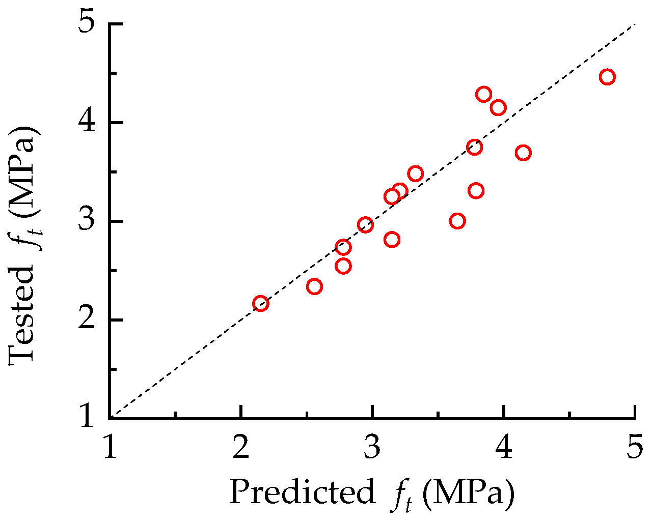
3.6. Relationship between Splitting Tensile Strength and Compressive Strength

The relationship between FFNSPC splitting tensile strength and compressive strength was compiled for the ease of engineering applications. The preceding analysis’s findings demonstrate that the replacement rate of FNSP affects splitting tensile strength as well as compressive strength, albeit these two effects may cancel each other out. The steel fiber composition significantly affects splitting tensile strength but has no effect on compressive strength. Figure 20 illustrates the relationship between splitting tensile strength and compressive strength under various steel fiber contents. It is evident that there is a linear relationship between the concrete’s splitting tensile strength and compressive strength with varying steel fiber contents. A higher steel fiber content in FFNSPC results in a higher splitting tensile strength under the same compressive strength.
Based on the above analysis results, a relationship between compressive strength and splitting tensile strength including fiber parameters was constructed. After fitting, the relationship is obtained as follows:
f t = 0.057 1 + 0.75 λ f f c
Figure 21 shows a comparison of the expected results of the aforementioned equation with the tested findings, where the dashed line denotes the reference line for the scenario in which the projected results are equivalent to the measured results. With a coefficient of variation of 0.6%, the mean value of the ratio between the test and projected outcomes is 0.968. The projected results closely match the tested findings, notwithstanding some discrepancies.

4. Conclusions

In this study steel fiber FNSP concrete was suggested as a way to increase the toughness of FNSP concrete, and a number of experiments were conducted to evaluate the mechanical performance of SFNSPC. The following are some of the primary results and conclusions:
(1)
With an increase in steel fiber content, the slump of SFNSPC under various FNSP replacement rates diminishes and essentially exhibits a linear declining pattern. The decline in SFNSPC is not statistically significant, but it does occur when the replacement rate of FNSP rises. The suggested ratio of SFNSPC slump to regular concrete yields good fitting results.
(2)
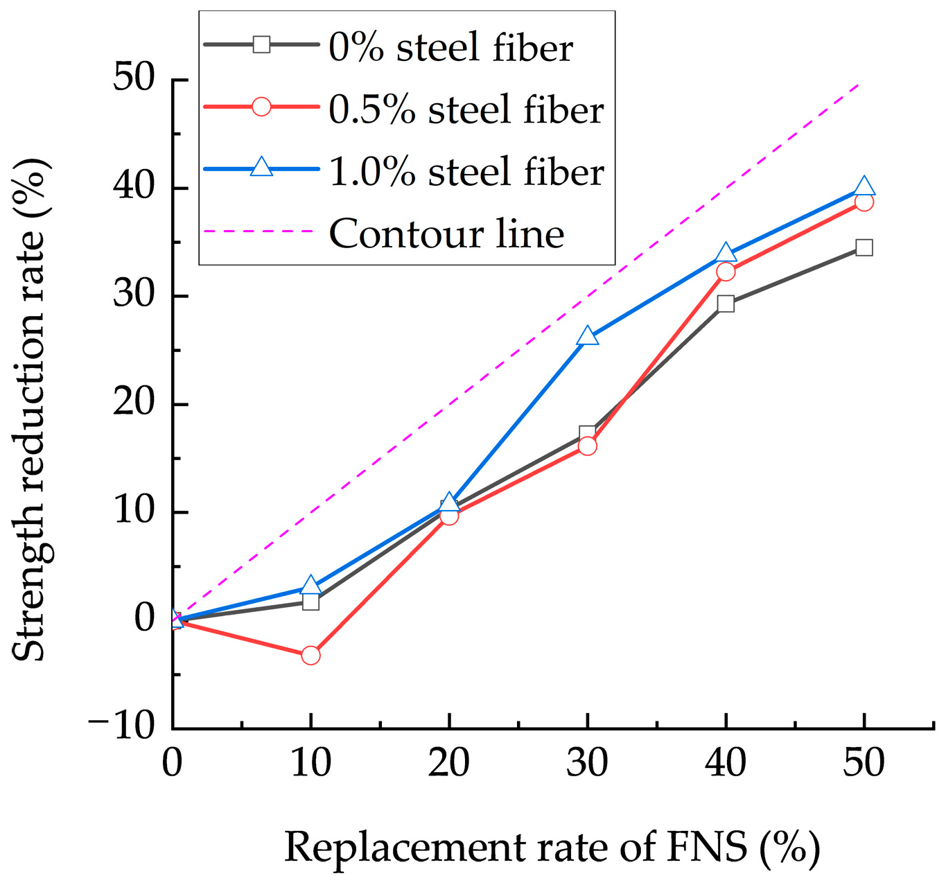
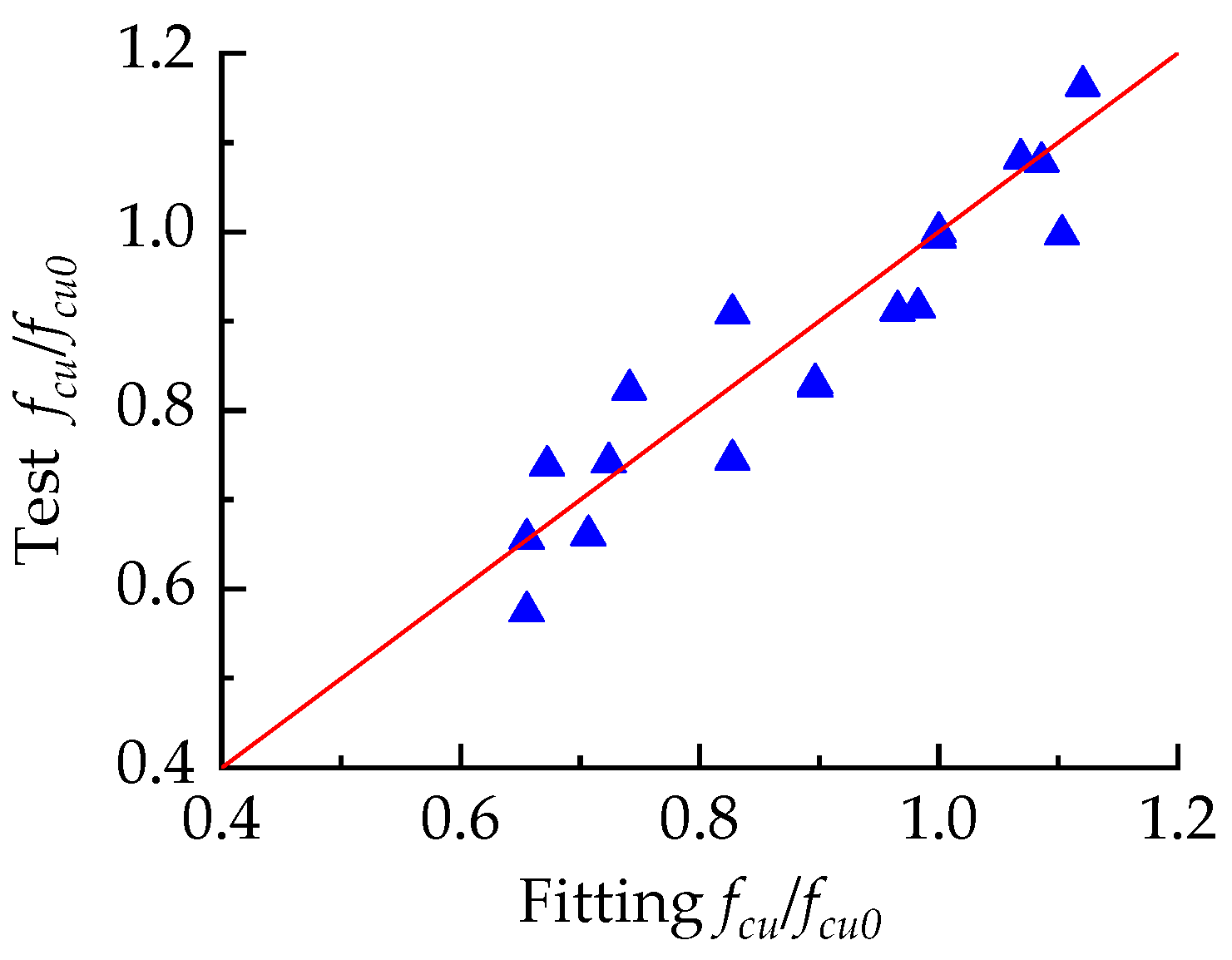
The compressive strength of SFNSPC is positively impacted by steel fibers, though not significantly. The compressive strength of SFNSPC reduces with a rise in the FNSP replacement rate under the same steel fiber content; however, this strength decrease is not statistically significant for small FNSP replacement rates. The viability of FNSP as an auxiliary cementitious material in terms of concrete strength is demonstrated by the fact that its replacement rate is consistently lower than the strength reduction rate. The suggested ratio of SFNSPC’s compressive strength to that of regular concrete fits the data quite well.
(3)
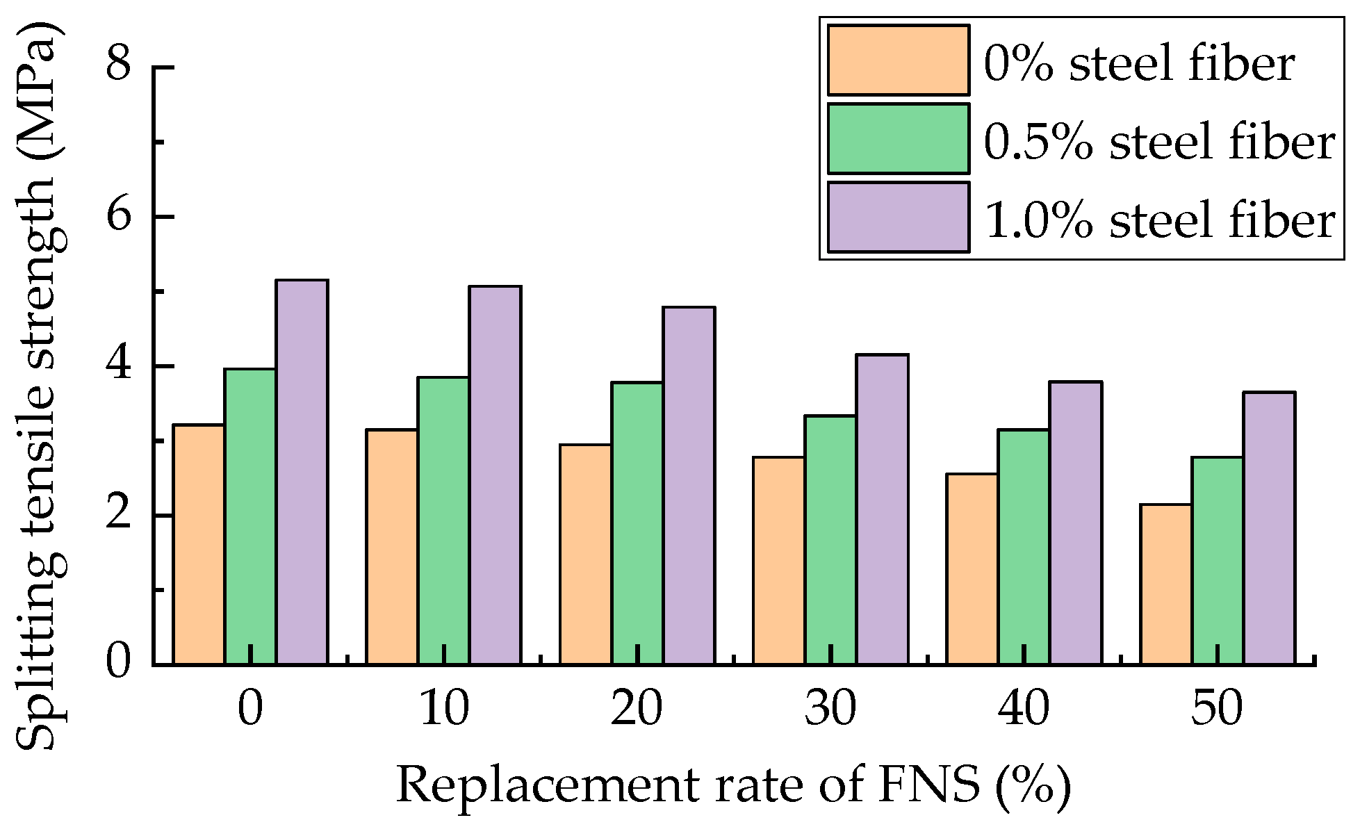
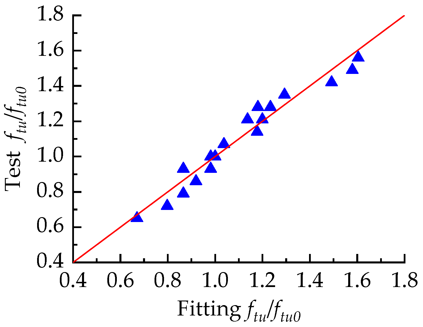
The splitting tensile strength of SFNSPC is significantly influenced by steel fibers, and it rises as the amount of steel fiber in SFNSPC increases. As the rate at which FNSP is replaced rises, so does the rate at which SFNSPC’s strength is reduced. The rate at which splitting tensile strength decreases is not as great as that of compressive strength, and the rate at which FNSP is replaced is consistently less than that of strength reduction. The suggested ratio of the splitting tensile strength of SFNSPC to that of regular concrete fits the data quite well.
(4)
By varying mix proportions, the stress–strain curve trend of SFNSPC is essentially consistent and mostly separates into the following sections: a rising part and a descending part. The descending portion of the curve is significantly influenced by the steel fiber composition. The descending section curve becomes smoother as the quantity of steel fibers increases. The SFNSPC specimens’ compressive toughness is positively impacted by steel fibers.
(5)
The toughness index is significantly impacted by steel fiber content; however it is not significantly affected by the replacement rate of FNSP at different levels of steel fiber content. The toughness index increases with the amount of steel fiber supplied. When 0.5% and 1.0% steel fiber is added to concrete with varying FNSP replacement rates, the toughness index rises by 8–30% and 12–43%, respectively, in comparison with SFNSPC without the addition of steel fibers.
(6)
In the design of SFNSPC, the replacement rate of FNSP and the content of steel fiber can be first established to determine the performance requirements. Then, the performance requirements of ordinary concrete can be established according to the relationship between the performance of SFNSPC and ordinary concrete. Finally, the mix ratio of ordinary concrete can be designed.

Author Contributions

Conceptualization, P.H., X.L. and Q.Z.; methodology, P.H.; validation, X.L., Q.Z. and F.F.; formal analysis, X.L.; investigation, X.L.; resources, X.L.; data curation, X.L. and F.F.; writing—original draft preparation, P.H.; writing—review and editing, X.L. and F.F.; visualization, Q.Z.; supervision, F.F.; project administration, Q.Z.; funding acquisition, F.F. All authors have read and agreed to the published version of the manuscript.

Funding

This study was funded by the Open Fund of the National Engineering Laboratory for Applied Technology of Forestry and Ecology in South China in 2023, grant number 2023NFLY01 and 2023NFLY02, and the Social Welfare Research Fund of Ningbo Science and Technology Bureau in 2022, grant number 2022S178.

Data Availability Statement

The original contributions presented in the study are included in the article, further inquiries can be directed to the corresponding author.

Conflicts of Interest

Author Pengcheng Hu was employed by the company Shengsi County Urban and Rural Construction Investment and Development Co., Ltd. The remaining authors declare that the research was conducted in the absence of any commercial or financial relationships that could be construed as a potential conflict of interest.

References

  1. Chang, Q.; Liu, L.; Farooqi, M.U.; Thomas, B.; Özkılıç, Y.O. Data-Driven Based Estimation of Waste-Derived Ceramic Concrete from Experimental Results with Its Environmental Assessment. J. Mater. Res. Technol. 2023, 24, 6348–6368. [Google Scholar] [CrossRef]
  2. Özkılıç, Y.O.; Zeybek, Ö.; Bahrami, A.; Çelik, A.İ.; Othuman Mydin, M.A.; Karalar, M.; Hakeem, I.Y.; Roy, K.; Jagadesh, P. Optimum Usage of Waste Marble Powder to Reduce Use of Cement toward Eco-Friendly Concrete. J. Mater. Res. Technol. 2023, 25, 4799–4819. [Google Scholar] [CrossRef]
  3. Saha, A.K.; Khan, M.N.N.; Sarker, P.K. Value Added Utilization of By-Product Electric Furnace Ferronickel Slag as Construction Materials: A Review. Resour. Conserv. Recycl. 2018, 134, 10–24. [Google Scholar] [CrossRef]
  4. Kim, H.; Lee, C.H.; Ann, K.Y. Feasibility of Ferronickel Slag Powder for Cementitious Binder in Concrete Mix. Constr. Build. Mater. 2019, 207, 693–705. [Google Scholar] [CrossRef]
  5. Sun, J.; Feng, J.; Chen, Z. Effect of Ferronickel Slag as Fine Aggregate on Properties of Concrete. Constr. Build. Mater. 2019, 206, 201–209. [Google Scholar] [CrossRef]
  6. Bao, J.; Yu, Z.; Wang, L.; Zhang, P.; Wan, X.; Gao, S.; Zhao, T. Application of Ferronickel Slag as Fine Aggregate in Recycled Aggregate Concrete and the Effects on Transport Properties. J. Clean. Prod. 2021, 304, 127149. [Google Scholar] [CrossRef]
  7. Nguyen, Q.D.; Castel, A.; Kim, T.; Khan, M.S.H. Performance of Fly Ash Concrete with Ferronickel Slag Fine Aggregate against Alkali-Silica Reaction and Chloride Diffusion. Cem. Concr. Res. 2021, 139, 106265. [Google Scholar] [CrossRef]
  8. Saha, A.K.; Sarker, P.K. Durability Characteristics of Concrete Using Ferronickel Slag Fine Aggregate and Fly Ash. Mag. Concr. Res. 2018, 70, 865–874. [Google Scholar] [CrossRef]
  9. Nuruzzaman, M.; Camargo Casimiro, J.O.; Sarker, P.K. Fresh and Hardened Properties of High Strength Self-Compacting Concrete Using by-Product Ferronickel Slag Fine Aggregate. J. Build. Eng. 2020, 32, 101686. [Google Scholar] [CrossRef]
  10. Qi, A.; Liu, X.; Wang, Z.; Chen, Z. Mechanical Properties of the Concrete Containing Ferronickel Slag and Blast Furnace Slag Powder. Constr. Build. Mater. 2020, 231, 117120. [Google Scholar] [CrossRef]
  11. Han, F.; Zhang, H.; Li, Y.; Zhang, Z. Recycling and Comprehensive Utilization of Ferronickel Slag in Concrete. J. Clean. Prod. 2023, 414, 137633. [Google Scholar] [CrossRef]
  12. Tang, Z.; Peng, H.; Mei, P.; Huang, F.; Yi, S.; Feng, F. Performance Analysis of Ferronickel Slag-Ordinary Portland Cement Pervious Concrete. Materials 2024, 17, 1628. [Google Scholar] [CrossRef]
  13. Qi, A.; Liu, X.; Xu, R.; Huang, Y. Bond Behavior of Steel Reinforcement in Concrete Containing Ferronickel Slag and Blast Furnace Slag Powder. Constr. Build. Mater. 2020, 262, 120884. [Google Scholar] [CrossRef]
  14. Liu, Q.; Chen, S.; Lin, W.; Qi, A.; Chen, Z. Experimental Behaviors of Prefabricated Members Made of Ferronickel Slag Concrete. Constr. Build. Mater. 2020, 261, 120519. [Google Scholar] [CrossRef]
  15. Liu, X.; Chen, S.; Qi, A.; Lin, W.; Wu, H. Flexural Performance of Reinforced Beams Made with Composite Ferronickel Slag Concrete. Constr. Build. Mater. 2021, 310, 125251. [Google Scholar] [CrossRef]
  16. Muthukumarana, T.V.; Arachchi, M.A.V.H.M.; Somarathna, H.M.C.C.; Raman, S.N. A Review on the Variation of Mechanical Properties of Carbon Fibre-Reinforced Concrete. Constr. Build. Mater. 2023, 366, 130173. [Google Scholar] [CrossRef]
  17. Abousnina, R.; Premasiri, S.; Anise, V.; Lokuge, W.; Vimonsatit, V.; Ferdous, W.; Alajarmeh, O. Mechanical Properties of Macro Polypropylene Fibre-Reinforced Concrete. Polymers 2021, 13, 4112. [Google Scholar] [CrossRef]
  18. Grzymski, F.; Musiał, M.; Trapko, T. Mechanical Properties of Fibre Reinforced Concrete with Recycled Fibres. Constr. Build. Mater. 2019, 198, 323–331. [Google Scholar] [CrossRef]
  19. Noor Abbas, A.-G.; Nora Aznieta Abdul Aziz, F.; Abdan, K.; Azline Mohd Nasir, N.; Fahim Huseien, G. Experimental Study on Durability Properties of Kenaf Fibre-Reinforced Geopolymer Concrete. Constr. Build. Mater. 2023, 396, 132160. [Google Scholar] [CrossRef]
  20. Li, W.; Shumuye, E.D.; Shiying, T.; Wang, Z.; Zerfu, K. Eco-Friendly Fibre Reinforced Geopolymer Concrete: A Critical Review on the Microstructure and Long-Term Durability Properties. Case Stud. Constr. Mater. 2022, 16, e00894. [Google Scholar] [CrossRef]
  21. Yıldızel, S.A.; Özkılıç, Y.O.; Bahrami, A.; Aksoylu, C.; Başaran, B.; Hakamy, A.; Arslan, M.H. Experimental Investigation and Analytical Prediction of Flexural Behaviour of Reinforced Concrete Beams with Steel Fibres Extracted from Waste Tyres. Case Stud. Constr. Mater. 2023, 19, e02227. [Google Scholar] [CrossRef]
  22. Yan, P.; Chen, B.; Afgan, S.; Aminul Haque, M.; Wu, M.; Han, J. Experimental Research on Ductility Enhancement of Ultra-High Performance Concrete Incorporation with Basalt Fibre, Polypropylene Fibre and Glass Fibre. Constr. Build. Mater. 2021, 279, 122489. [Google Scholar] [CrossRef]
  23. GB/T 14684-2011; Specification of Sand for Building, General Administration of Quality Supervision. Inspection and Quarantine of the People’s Republic of China: Beijing, China, 2011. (In Chinese)
  24. Wang, D.; Wang, Q.; Zhuang, S.; Yang, J. Evaluation of Alkali-Activated Blast Furnace Ferronickel Slag as a Cementitious Material: Reaction Mechanism, Engineering Properties and Leaching Behaviors. Constr. Build. Mater. 2018, 188, 860–873. [Google Scholar] [CrossRef]
  25. Chi, L.; Lu, S.; Li, Z.; Huang, C.; Jiang, H.; Peng, B. Recycling of Ferronickel Slag Tailing in Cementitious Materials: Activation and Performance. Sci. Total Environ. 2023, 861, 160706. [Google Scholar] [CrossRef]
  26. Zhou, Y.; Shi, C. Experimental Study of Electric Furnace Ferronickel Slag as a Supplementary Cementitious Material in Massive High-Strength Concrete. J. Therm. Anal. Calorim. 2022, 147, 4983–4993. [Google Scholar] [CrossRef]
  27. Zhai, M.; Zhu, H.; Liang, G.; Wu, Q.; Zhang, C.; Hua, S.; Zhang, Z. Enhancing the Recyclability of Air-Cooled High-Magnesium Ferronickel Slag in Cement-Based Materials: A Study of Assessing Soundness through Modifying Method. Constr. Build. Mater. 2020, 261, 120523. [Google Scholar] [CrossRef]
  28. Chen, Y.; Ji, T.; Yang, Z.; Zhan, W.; Zhang, Y. Sustainable Use of Ferronickel Slag in Cementitious Composites and the Effect on Chloride Penetration Resistance. Constr. Build. Mater. 2020, 240, 117969. [Google Scholar] [CrossRef]
  29. GB/T 50081-2019; Standard for Test Methods of Concrete Physical and Mechanical Properties. China Construction Industry Press: Beijing, China, 2019.
  30. Zheng, J.; Qi, L.; Zheng, Y.; Zheng, L. Mechanical Properties and Compressive Constitutive Model of Steel Fiber-Reinforced Geopolymer Concrete. J. Build. Eng. 2023, 80, 108161. [Google Scholar] [CrossRef]
Figure 1. Roadmap of this work.
Buildings 14 02471 g001
Figure 2. Particle size distribution of aggregates: (a) coarse aggregate and (b) fine aggregate.
Buildings 14 02471 g002
Figure 3. Photo and particle size distribution of FNSP: (a) FNS; (b) FNSP; and (c) particle size distribution.
Buildings 14 02471 g003
Figure 4. SEM image of FNSP: (a) 1000×; (b) 2000×; (c) 5000×; (d) 10,000×; (e) 20,000×; and (f) 50,000×.
Buildings 14 02471 g004aBuildings 14 02471 g004b
Figure 5. EDS elemental mapping of individual elements in FNSP: (a) C; (b) O; (c) Si; (d) Al; (e) Ca; (f) Mg; (g) S; (h) Na; and (i) Cd.
Buildings 14 02471 g005
Figure 6. Steel fiber.
Buildings 14 02471 g006
Figure 7. Concrete strain gauge.
Buildings 14 02471 g007
Figure 8. Slump results.
Buildings 14 02471 g008
Figure 9. Fitting result of slump.
Buildings 14 02471 g009
Figure 10. Compressive strength of SFNSPC.
Buildings 14 02471 g010
Figure 11. Reduction rate of the compressive strength of SFNSPC.
Buildings 14 02471 g011
Figure 12. Fitting result of compressive strength.
Buildings 14 02471 g012
Figure 13. Splitting tensile failure mode of SFNSPC.
Buildings 14 02471 g013
Figure 14. Splitting tensile strength of SFNSPC.
Buildings 14 02471 g014
Figure 15. The reduction rate of SFNSPC’s splitting strength with different FNSP replacement rate.
Buildings 14 02471 g015
Figure 16. Splitting tensile strength fitting results.
Buildings 14 02471 g016
Figure 17. The uniaxial compressive stress–strain curve of FFNSPC: (a) FFNSPC with 0% FNSP; (b) FFNSPC with 10% FNSP; (c) FFNSPC with 20% FNSP; (d) FFNSPC with 30% FNSP; (e) FFNSPC with 40% FNSP; (f) FFNSPC with 50% FNSP.
Buildings 14 02471 g017aBuildings 14 02471 g017b
Figure 18. Schematic diagram for calculating toughness indicators.
Buildings 14 02471 g018
Figure 19. Toughness index.
Buildings 14 02471 g019
Figure 20. The relationship between splitting tensile strength and splitting tensile strength.
Buildings 14 02471 g020
Figure 21. Comparison between the predicted and tested results.
Buildings 14 02471 g021
Table 1. Coarse aggregate testing indicators.
Apparent Density
kg/m3
Natural Packing Density
kg/m3
Water Absorption Rate
%
Crushing Index
%
Clay Lump
%
Void Rate
%
Indicator requirements≥2500≥1350<2.0<20<0.5<47
Tested result275015700.4013.500.1035.6
Table 2. Fine aggregate testing indicators.
Apparent Density
kg/m3
Fineness ModulusBulk Density
kg/m3
Crushing Index
%
Clay Lump
%
Stone Powder Content
%
Indicator requirements≥25002.3–3.0≥1350<25<1.0<7
Tested result27502.71621130.35.9
Table 3. Composition of FNSP.
ComponentCaOSiO2Al2O3MgOSO3MnOOthers
%35.5830.9116.7110.272.251.123.16
Table 4. Mix proportions.
No.Water
/kg
Cement
/kg
FNS
/kg
Sand
/kg
Coarse Aggregate
/kg
Fly Ash/
kg
Superplasticizer/%Steel Fiber/
%
C-0-016238306171147590.90
C-10-0162345386171147590.90
C-20-0162306776171147590.90
C-30-01622681156171147590.90
C-40-01622301536171147590.90
C-50-01621921926171147590.90
C-0-0P516238306171147590.90.5
C-10-0P5162345386171147590.90.5
C-20-0P5162306776171147590.90.5
C-30-0P51622681156171147590.90.5
C-40-0P51622301536171147590.90.5
C-50-0P51621921926171147590.90.5
C-0-1P016238306171147590.91.0
C-10-1P0162345386171147590.91.0
C-20-1P0162306776171147590.91.0
C-30-1P01622681156171147590.91.0
C-40-1P01622301536171147590.91.0
C-50-1P01621921926171147590.91.0
Disclaimer/Publisher’s Note: The statements, opinions and data contained in all publications are solely those of the individual author(s) and contributor(s) and not of MDPI and/or the editor(s). MDPI and/or the editor(s) disclaim responsibility for any injury to people or property resulting from any ideas, methods, instructions or products referred to in the content.

