Abstract
The paper deals with frame steel structures required to ensure sufficient resistance, appropriate ductility and safety against brittle failure. This special aim cannot be reached by utilizing standard procedures and standard beam elements. Therefore, the present study proposes an innovative design strategy devoted to plane steel frames constituted by I-shaped cross-section beam elements and subjected to simultaneous combinations of serviceability limit state conditions and ultimate limit state conditions. Special factory-made I-shaped uniform piecewise steel profiles are utilised to provide the optimal behaviour of the frame. The proposed design strategy consists of two subsequent steps: at first a classical sizing of the frame is performed by utilising standard steel profiles, then a specific optimal design problem is performed to define the optimal geometry of the I-shaped steel profiles that fulfils all the constraints related to the required resistance and the limited deformability as well as special introduced constraints related to the protection against the brittle failure. The reliability of the procedure and the expected optimal behaviour of the frame are checked by performing nonlinear static analyses employing a recently proposed Fibre Smart Displacement-Based (FSDB) beam element model. The proposed beam element is defined by adopting displacement shape functions capable of embedding the cross-section discontinuities by means of the use of generalised functions. Furthermore, the proposed shape functions are addressed to as “smart” since capable of update in accordance with the development of plastic deformations detected by means of fibre discretisation of the cross-section. The results related to a simple steel portal confirmed the expected optimal behaviour of the structure.
1. Introduction
Structural mechanics is characterized by two different main issues: the verification problem and the optimal design problem. The first one consists of a first phase (analysis) in which the response of the known structure subjected to given loads is determined, and of a second essential phase in which fulfilment of the basic hypotheses to perform the analysis (related to the material and/or structure strength limit and to appropriate kinematical constraints) is verified. The second problem consists in the search for the optimal value of predefined relevant design quantities (design variables) so that appropriate kinematical constraints and assigned material and/or structure strength limits are fulfilled. In practical engineering, the verification problem is very common, and it faces mainly existing structures (buildings, bridges, etc.). Clearly, the need to recover or make compliant to national and international standards, or simply the maintenance of the huge existing building heritage strongly requires the adoption of more and more accurate techniques of structural verification and analysis. The design problem, on the other hand, is formally defined for new structures, even though it also constitutes an essential part of the interventions related to structural adaption or improvement on existing structures. The two problems adopt mainly the same instruments: suitable geometrical and mechanical models to describe the structural elements, selected constitutive models able to describe the mechanical behaviour of the materials and appropriate models to describe the loadings. The definition of these models is related both to the special structure to be investigated and/or designed and to the imposed behavioural features. In the literature, many formulations can be found for solving both the verification problem for steel structures subjected to static [1,2], dynamic [3] and stochastic actions [4,5] and the optimal design one [6], adopting constraints on different limit load conditions [7,8], taking into account the prevention of buckling phenomena [9,10,11], evaluating the influence of the residual deformations [12,13], adopting appropriate protection systems in seismic conditions [14,15] and considering the presence of base isolation systems [16]. It is important to emphasize that the design problem requires in general formulations more complex than the verification problem and the related mathematical problem is usually strongly nonlinear. For this reason, in practical applications, the design problem is often solved by utilising simplified approaches able to give iteratively at least a sub-optimal solution.
The present paper is devoted to the design problem and reference will be made to steel structures, given the great growth they have had in recent centuries.
Actually, since the industrial revolution age, due to the relevant fundamental technological innovations, there has been a great increase in the production of metallic materials (mainly cast iron and steel) with a corresponding decrease in the production costs. This favourable background allowed an increasingly widespread adoption of these materials also in the construction industry whereas until that period they were adopted only for accessory elements such as anchoring and tie-rods. The first examples of the adoption of metallic materials in the construction industry were bridges, industrial warehouses, railway stations and structural elements of buildings. The adoption of metallic materials was also promoted by the development of the structural mechanics which provided the theoretical basis as well as the technical instruments to design metallic structures. Between the end of the 19th century and the beginning of the 20th century, the use of metallic materials spread both across Europe, with particular reference to England and France, and in the USA, where the first skyscrapers were built. Among the structural typologies available to the designers, frames represent the more widely adopted both in civil and industrial constructions. Due to the peculiar characteristics of metallic materials, steel structures are certainly the more endorsed ones in terms of strength, weight, durability, construction speediness, space usability, material quality and behaviour flexibility. Besides the already mentioned mechanical properties, their ductility makes steel framed structures very competitive especially in seismic design. The designer can take advantage of the high energy dissipation characterizing steel frames as well as of their high strength, allowing the design of more and more performant structures.
On this basis, researchers devoted some attention to study the case of steel framed structures in view of the recognised good features of this structural typology. The latter is extremely versatile and adequate to provide optimal response to the different load combinations to be withstood during structure lifetime.
Moreover, recognising that a critical topic of the frame structure is related to the affordability of the connections [17,18,19], in order to enhance the special features of this structural typology and with the aim of improving the steel frame behaviour, in previously published papers the authors proposed the formulation of special devices realising new connections between beams and columns [20,21,22,23,24,25,26,27,28]. In particular, the starting idea has been described in [20,21] where a rigid perfectly plastic hinge has been defined, characterized by suitably chosen stiffness and resistance to be inserted in a steel frame; subsequently, the optimal dimensions of the device have been investigated by suitable Finite Element Method analyses in [22,23] obtaining a recommendation about the minimum length of the inner part; in [24] the optimal design of the device has been improved taking into account the simultaneous presence of axial force and bending moment; in [25] the presence of the device in a structural element has been modelled by a smart beam element approach while in [26] the proposed device has been adopted to design a steel frame able to replace a portion of a masonry panel without modifications of the overall mechanical behaviour; in [27] the role of buckling in the optimal design of the device has been considered while in [28] the proposed device has been adopted to design a steel frame avoiding brittle rupture in the welded connections. The innovative device proposed in the referenced papers, referred to as Limited Resistance Plastic Device (LRPD), is devoted to fulfilling the following main requisites:
- (i)
- create a preset zone of the beam element in which plastic deformations develop, leaving the remaining part of the beam element in the elastic range;
- (ii)
- design the device such that its flexural stiffness and resistance can be suitably as-signed while remaining independent of each other, so avoiding any stiffness variation in the involved beam element.
The proposed device, from a general point of view, can be considered as belonging to the broader class of so-called Reduced Beam Section (RBS) connections, but it possesses some further special features that make the device more widely usable [26,28].
In order to obtain an extension of the previous studies, the main aim of the present paper is to propose a specific iterative strategy to obtain the optimal design of steel framed structures constituted by multi-stepped I-shaped beam elements. A structural member with multi-stepped geometric characteristics should comprise some weak zones with suitable dimensions where plastic strain can develop, while the remaining zones should be designed in such a way that a target overall stiffness of the element as well as ductile behaviour are ensured.
The main novelty of the present study consists in the proposal of an innovative iterative design procedure specifically aimed at obtaining a steel framed structure able to show a comprehensive optimal behaviour in terms of strength, usability and ductility depending on the different loading conditions, while also ensuring appropriate safety conditions against brittle failure. Specifically, two different loading conditions are considered: in the first one (the serviceability condition), the structure will respect suitable strength requirements and deformability constraints; in the second one (the ultimate limit load condition), beyond the given strength requirements, the structure will have to show a high ductility behaviour. In both cases, ad hoc strength constraints able to avoid any risk of brittle failure of the welded connections are imposed. The considered load conditions will be referred to as dead loads and cyclic loads; appropriate load combinations will be introduced utilising load amplifiers as provided by the current international standards [29,30,31].
The need for optimal structures possessing the described features can be satisfied by designing non-standard beam elements; consequently, in the relevant search problem appropriate multi-stepped beam elements will be adopted for both beams and columns. The adoption of this special beam element typology will ensure the desired pronounced ductile behaviour of the structure. The adoption of multi-stepped beam elements as objects of the above design problem and the proposed iterative design strategy represent the main novelties of the paper. Furthermore, aiming at a full nonlinear analysis of the designed steel frame, a nonlinear finite element embedding cross-section discontinuities is also formulated. The proposed finite element is an extension of the Fibre Smart Displacement-Based (FSDB) beam element model presented in [32,33]. The FSDB element is endowed with displacement shape functions denoted as “smart” in view of their ability to evolve in accordance with the plastic deformation development. The proposed element is enriched with abrupt variations of the cross-sections, as obtained by the iterative design procedure, to avoid any subdivision of the frame elements into sub-elements.
In the paper, first, the optimal design procedure is formulated, then, the extension of Fibre Smart Displacement-Based (FSDB) beam element model to embed the designed discontinuities is presented. Finally, an application related to the design of a simple plane steel frame is given showing the great advantages and affordability of the proposed approach.
2. Optimal Design Strategy
The optimal design strategy here presented is formulated, for the sake of simplicity and clarity, with reference to a simple steel portal. It is worth noting that the extension of the formulation to multi-span and multi-floor frames is trivial.
Therefore, the optimal design of a plane steel portal subjected to dead loads and cyclic (quasi-static) loads is searched. Two different load combinations are considered [31]: the so-called characteristic combination (serviceability limit state conditions) and the so-called fundamental combination (ultimate limit state conditions), both defined as linear combination of the acting loads by suitable coefficients indicated in the following.
An elastic perfectly plastic behaviour of the material is considered, and it is imposed that the structure fulfils appropriate constraints on displacements in serviceability conditions and that it possesses pronounced ductility in ultimate limit load conditions, always ensuring a safe behaviour against local and/or global collapse phenomena. Further, it is also required that the base sections of the columns and the end sections of the beam, which typically consist in a welded connection, be preserved from brittle failure phenomena.
All the frame elements (beam and columns) are constituted by factory-made I-shaped multi-stepped steel profiles; in particular, the columns are constituted by three subsequent portions and the beam by five subsequent portions. The geometry of the beam elements is better described in Figure 1.
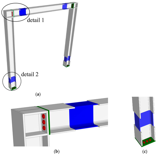
Figure 1.
Steel frame (green: plate; red: bolts; blue: reduced section portion): (a) overall view; (b) detail 1, sketch of the beam-column connection; (c) detail 2, sketch of the column base.
The searched optimal design is the minimum volume one (minimum cost).
The relevant problem is formulated in two subsequent steps. First, the minimum volume design of the portal with assigned geometry (given span and height measured along the element axes) and subjected to the given load combinations is determined (Figure 2).
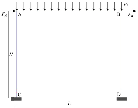
Figure 2.
Sketch of the steel frame: geometry and load conditions.
In this step, each beam element has a constant I-shaped cross-section (to be determined as solution to the search problem) with an assigned width and depth. The latter are determined by a preliminary sizing of the frame performed utilizing standard I-shaped steel profiles available on the market (which play the role of reference standard cross-sections) exactly according with the rules indicated by the classic international standards. In particular, with the aim of optimising the structural volume as much as possible, the standard cross-sections are designed as the ones for which the frame violates the standard rules as little as possible. Therefore, having determined the width and depth of the first step design and assigned the common web thickness to ensure sufficient shear resistance and that the cross-sections belong to Class 1 [31], the optimal thickness of the cross-section flanges is determined for the portal which fulfils both an appropriate constraint on the horizontal drift in serviceability limit state (SLS) conditions and appropriate constraints on the yield strength in ultimate limit state (ULS) conditions , with and given load coefficients. As prescribed by the standards, the analysis of the structure is performed by solving a linear elastic problem and the related response is determined.
In the second step, the minimum volume problem of the frame constituted by I-shaped multi-stepped beam elements is performed. The optimal thicknesses of the flanges and the optimal geometry of each cross-section of the beam elements are determined. Again, it is required that in SLS conditions the portal fulfils the previously described constraint on the horizontal drift, its response being perfectly elastic, and, moreover, that in ULS conditions it shows the onset of plastic deformations in predetermined portions of the constituting elements (so as to take advantage of the material’s proper ductility), but always ensuring the protection of the welded connections against brittle failure. The constraints on the cross-section resistance are imposed by referring to the stress field obtained as response to the first step; in particular, in correspondence to the “weak cross-sections”, where the onset of plastic deformations is required, the yield condition is imposed just for the stresses obtained as response to the first step. Such a procedure provides a sufficiently reliable sub-optimal design since the constraints on the horizontal drift are the same in both the two subsequent steps and this occurrence ensures that the frame possesses analogous stiffness features. It is worth noting that the second step phase can be iteratively performed to obtain more and more stringent designs.
The proposed design strategy introduces significant novelties with respect to the existing design procedures known in the scientific literature and/or prescribed by the international standards. It is based on the requirement of realizing a structure possessing strength and stiffness independent of each other, and the choice of I-shaped multi-stepped beam elements meets this requirement. In fact, the weak portions allow both volume reduction and the utilization of the structure’s ductility features, while the strong portions ensure the required stiffness and protection against brittle failure.
The I-shaped multi-stepped beam element design represents a generalization to a wider scale of the use of the known Limited Resistance Plastic Devices (LRPDs) [20,21,22,23,24,25,26,27,28]. Furthermore, the described new design procedure also allows the control of the behaviour of the welded connections. Finally, the proposed strategy and the idea of realizing the whole optimal structural beam element with stepped cross-sections represents an additional novelty and allows an easy technological realization.
2.1. Optimal Design Problem Formulation: First Step
As previously stated, the first step consists in the search for the minimum volume design of the portal with the assigned geometry (given span and height measured along the beam element axes) and subjected to the given combinations of dead and cyclic loads. A constant I-shaped cross-section is assigned to each beam element; width and depth of the beam element cross-sections are determined by a preliminary sizing of the frame performed utilizing standard steel profiles available on the market. Once the web thicknesses have been assigned in advance to the relevant cross-sections, the optimal thickness of the cross-section flanges is determined for the portal which fulfils an appropriate constraint on the horizontal drift in SLS conditions and fulfils constraints on the yield strength in ULS conditions.
The following quantities are given:
- length of the columns (left, right) and of the beam;
- cross-section width of the columns (left, right) and of the beam;
- cross-section depth of the columns (left, right) and of the beam;
- web thickness of the columns (left, right) and of the beam;
- material yield stress;
- maximum admissible horizontal drift;
- uniformly distributed dead load;
- cyclic load vector;
- cyclic load multiplier for serviceability limit state conditions;
- load multiplier for ultimate limit state conditions.
The design variable vector is:
In Equation (1), are the flange thicknesses of the columns (left, right) and of the beam, and are the vectors of nodal displacements, each of six components, response to the load combinations , respectively.
The objective function to be minimized (structural volume) is:
where is the cross-section area of the columns (left, right) and of the beam.
The minimum volume design problem can be written in the following form:
subjected to:
Equation (4) represents the constraints ensuring that the sections belong to Class 1, together with the trivial geometric upper bound; Equation (5) represents the constraints on the displacements in SLS conditions; Equation (6) represents the elastic response to serviceability limit state conditions, with being the compatibility matrix, the internal stiffness matrix and , where is a perfectly clamped generalised elastic stress response vector; Equations (7) and (8) represent the constraints on the yield strength in ultimate limit state conditions, with cross-section plastic modulus of columns and beam, where are suitable coefficients depending on the shape of the yield boundary domain of the cross-sections of columns and beam fulfilling the constraints in Equation (9). Furthermore, in Equations (7) and (8): is the component of the generalised elastic stress response vector to the load combinations . It is worth noting that, due to the symmetry of the relevant cross-section yield domain, in Equations (7) and (8) the absolute values of the components of the generalised elastic stress response vector have been considered.
2.2. Optimal Design Problem Formulation: Second Step
The second step of the design strategy is devoted to the search for the minimum volume of the frame constituted by I-shaped multi-stepped beam elements. In addition to the previously described kinematical constraints, in SLS conditions it is required that the structural response be perfectly elastic (in order to ensure the efficacy of the kinematical constraints), while in ULS conditions it is required that the structure shows the onset of plastic deformations in predetermined portions of the beam elements, ensuring in addition the protection of the welded connections against the brittle failure. As previously stated in this step reference is made to the stress response obtained at first step.
Referring to Figure 3, the following quantities are given:
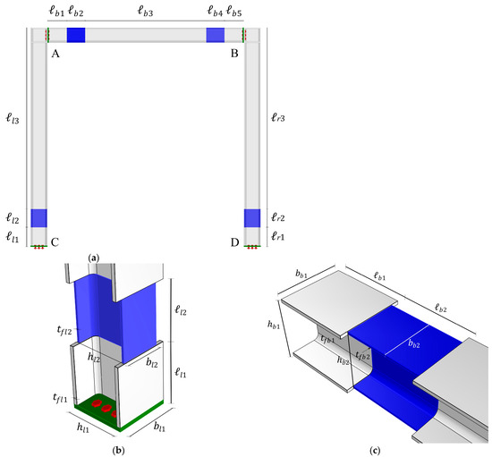
Figure 3.
Geometric characteristic of the multi-stepped beam element frame: (a) lengths of the different portions of the beam elements; (b) specific dimensions of the portions at the left column base; (c) specific dimensions of the portions at the left beam end.
- , , , , , , , , ;
- , , ;
- , , ;
- , ;
- .
In the above, in addition to the symbols already introduced, and are the widths of the original left and right column cross-sections, respectively, and is the width of the original beam cross-section. Analogously, and are the depths of the original left and right column cross-sections, respectively, and is the depth of the original beam cross-section.
The design variables are the following:
- , , , , ,,
where is the common thickness of the strong portions of the left column, is the common thickness of the strong portions of the right column and is the common thickness of the strong portions of the beam.
The objective function to be minimized (structural volume) is:
By trivial geometry, stipulating that the cross-section flanges of subsequent beam element portions have the same medium plane, the result must be:
The minimum volume design problem can be written in the following form:
subjected to:
Equation (13) represents the constraints ensuring that the sections belong to Class 1 together with the trivial geometric upper bound; Equation (14) represents the constraints on the displacements in SLS conditions; Equation (15) represents the elastic response to serviceability limit state conditions, with internal stiffness matrix of the I-shaped multi-stepped beam elements, the elements of which will be defined in the following section; Equation (16) represents the constraints on the limit elastic resistance of the weak portions in ULS conditions, where is the relevant cross-section elastic modulus and a suitable coefficient representing the ratio between yield limit bending moment and elastic limit bending moment (typically the range 1.10÷1.15 can be adopted for related to I-shaped cross-sections); Equation (17) represents the constraints on the limit brittle resistance of the welded connections in ULS conditions with being a suitably chosen safety coefficient ( can be adopted. See Table 4.2.XIV [31]).
3. Multi-Step Beam Element Model Formulation
The optimisation procedure presented in the previous sections leads to the identification of a steel frame composed of multi-stepped elements with an I-shaped cross-section. The optimised frame has been suitably designed to respect the chosen constraints and is prone to development of plastic deformations along pre-established portions of the elements. Since the optimisation procedure does not account for a proper nonlinear analysis, in order to verify the actual performance of the frame a full nonlinear incremental analysis is mandatory. The relevant strategy presented in this section is a customised version of the Fibre Smart Displacement-Based (FSDB) procedure presented by some of the authors in [32,33]. In particular, a novel beam element was formulated by means of the introduction of suitable shape functions of the transversal displacements which are able to update during the nonlinear analysis. The ability of the proposed adaptive displacement shape functions consists in taking into account the real distribution of the stiffness along the span depending on the development of plastic deformations. The FSDB approach has been applied successfully to model moment-resisting connections denoted as LRPD devices in [26] and it is here customised to model beam elements characterised by multi-step variations according to the scheme adopted in Figure 3.
Precisely, each beam/column element of the frame in Figure 3 is modelled as a discontinuous beam characterised by piecewise constant cross-sections where abrupt variations of the cross-section occur at . According to the optimum design problem formulated in the previous section giving rise to the presence of weak portions in the left and right columns as well as in the beam, the cross-section discontinuities occur at abscissae , (), , (), , (), in the left column, the beam and the right column, respectively.
Within the context of a distributed plasticity approach [32,33], during the nonlinear analysis, the onset of plastic deformations is allowed at pre-established Gauss cross-sections at abscissae determined in accordance with the chosen integration scheme. The occurrence of plastic deformations at Gauss cross-sections gives rise to further discontinuities affecting both the axial and the flexural stiffness of the frame elements. The proposed FSDB approach, here adopted, ascribes the discontinuities to the axial and flexural stiffness distribution of the beam by making use of generalised functions and, specifically, the Heaviside (unit step) generalised function , (defined as for ; for ). The governing equations of an Euler–Bernoulli beam characterised by cross-section discontinuities, due to the presence of weak portions, and additional discontinuities of the axial and flexural stiffness at the Gauss cross-sections, due to the onset of plastic deformations, subjected to axial and transversal load distributions can be written as follows:
where the apex indicates the differentiation with respect to spanning from 0 to the length of the beam, and , are the axial displacement and the transversal deflection functions; furthermore, represents the Young modulus and are the cross-section area and moment of inertia, respectively, of the columns (left, right) and the beam as determined in the first step of the design procedure.
In Equations (18) and (19), , , with , represent the normalized variation of the current axial and flexural stiffness of the columns and beam segments as determined in the second step of the design procedure with respect to the values and obtained in the first step.
Furthermore, in order to account for the axial and flexural stiffness degradation due to the occurrence of plastic deformations during the nonlinear analysis, the stepped beam model with the cross-section discontinuities formulated in Equations (18) and (19) has been further enriched by means of the introduction of additional parameters which are updated during the inelastic analysis to take into account the axial and flexural stiffness degradation. Precisely, the parameters introduced in Equations (18) and (19) take the initial values , corresponding to a fully elastic state, and are subjected to a step-by-step updating within the range , being corresponding to a fully plastic state of the relevant Gauss cross-section.
In order to perform the nonlinear elastic plastic analysis of the designed multi-step frame, in what follows the closed form solution of the governing Equations (18) and (19) are exploited.
Integration of Equations (18) and (19), by making use of the Schwartz theory of distributions, leads to the following explicit expressions for the axial displacement and the transversal deflection functions , respectively:
where are integration constants and the functions dependent on the parameters and , are defined as follows:
The explicit solution reported in Equations (20) and (21) can be exploited to conduct a nonlinear analysis by updating the values of the parameters and obtained by suitable integration of the constitutive laws at each Gauss cross-section. For this purpose, the solution of the stepped beam model in Equations (20) and (21) is adopted to introduce a beam/column element, connecting joints and , in the plane as shown in Figure 4. The vectors , , collecting the nodal displacements , and the nodal forces , , respectively, reported in Figure 4, are introduced.

Figure 4.
Nodal degrees of freedom (a) and forces (b) of the element.
Based on Equations (20) and (21), the axial/transversal displacement shape functions , obtained by imposing unit nodal displacements and evaluating the integration constants, can be formulated as follows:
where:
The displacement shape functions proposed in Equations (27)–(33) account for the discontinuities introduced in the second step of the optimal design problem by means of the parameters , . Furthermore, in contrast with the classic displacement shape functions, they are subjected to evolution being able to adapt to the inelastic state of the element through the parameters dependent on the evolution of the plastic deformations. For the latter reason, the presented shape functions can be addressed to as Smart Displacement Shape Functions (SDSFs).
The stiffness matrix of the beam element defined in Figure 4, representative of the beam/columns of the discontinuous frame designed by means of the optimisation procedure described in the previous sections, can now be built. Precisely, according to a fibre approach, each Gauss cross-section at , , is discretised into strips (denoted as fibres), as in Figure 5, with an area , . Each fibre undergoes a nonlinear uniaxial stress–strain relationship modelling constitutive behaviour characterised by the tangent modulus .
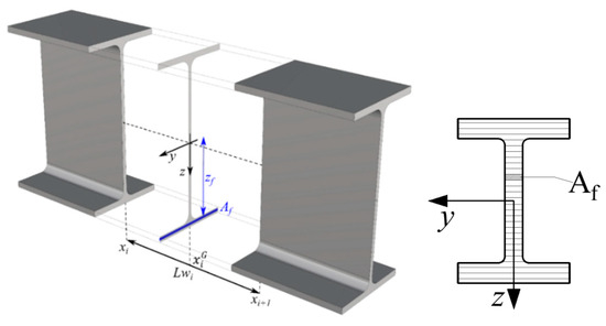
Figure 5.
Fibre discretization of a I-shaped Gauss cross-section.
By assuming the principle of planar section conservation, the axial strain of each fibre is written in terms of nodal displacements as:
where the row vector , dependent on the distance of the f-th fibre from the beam axis, has been introduced, and the matrix , dependent on the stiffness decay parameters is defined in terms of derivatives of the displacement shape functions as follows:
Furthermore, the stiffness matrix of the generic Gauss cross-section, in view of the fibre discretisation as shown in Figure 5, can be given as follows:
By standard application of the principle of virtual displacements, and the subsequent application of the Gauss integration scheme, the stiffness matrix of the beam/columns elements of the designed frame is obtained as follows:
where denotes the weight of each Gauss point. The stiffness matrices reported in Equation (37), depend on the discontinuity parameters being updated during the inelastic analysis. It has to be remarked that by block diagonal assemblage of the stiffness matrices the matrix appearing in Equation (15) is recovered.
The cross-section stiffness matrix at each Gauss cross-section is evaluated by performing a parallel integration of the uniaxial nonlinear constitutive laws at each fibre in the step-by-step analysis that delivers the current tangent stiffness modulus appearing in Equation (36).
Finally, once integration of the nonlinear constitutive laws has been performed at fibre level, the updating of the stiffness parameters, , , is obtained straightforwardly, by accounting for the coupling between the axial and flexural behaviour, as follows:
dependent on the increments of axial deformation of the geometrical axis and curvature of the cross-section defined in terms of nodal displacements as follows: .
The step-by-step evaluation of the stiffness parameters , , in accordance to Equations (38) and (39), allows the updating of the SDSFs in Equations (27)–(33), of the deformation matrix in Equation (35) and of the element stiffness matrix in Equation (37). The smart character of these matrices allows the adoption of a single SDB element for each beam/column preventing any sub-discretisation.
4. Application
To validate the efficacy and the affordability of the proposed design strategy, reference has been made to a simple steel portal. In Figure 6, the schematic drawing of the structure is shown referring to the beam element axes together with the considered acting basic loads (dead load and perfect cyclic load ). Furthermore, an elastic perfectly plastic behaviour (, ) is assumed for the constituting material.
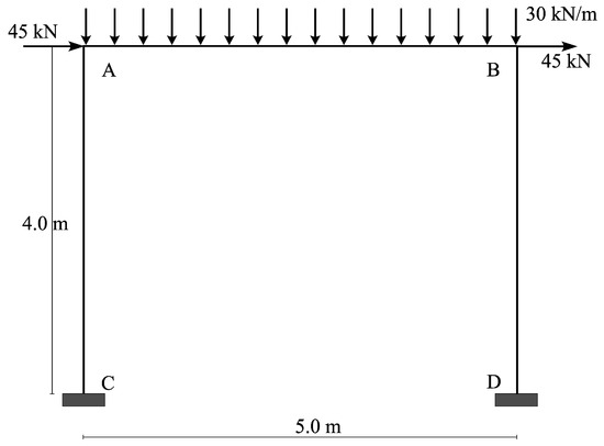
Figure 6.
Frame to be designed.
With the aim of defining the reference data (width and depth of the cross-section of each beam element) to perform the proposed iterative procedure, it is necessary to preliminarily execute a first sizing of the structure elements and to define a first attempt cross-section design. Therefore, following the requirements of the referenced structural standard [31], the beam elements are designed for the frame to be subjected to two different load combinations: the serviceability limit state condition and the limit state condition , namely and .
For this first design, I-shaped steel profiles (HEB) are chosen, and it is assumed that all the elements are constituted by the same profile. As required by the standard, the design is searched by performing a linear elastic analysis imposing constraints on displacements for serviceability conditions and constraints on the yield behaviour for limit load conditions. In particular, the maximum horizontal drift in serviceability limit state conditions does not exceed 15 mm (equal to ¾ of the 5‰ of the frame height) and the stress field in ultimate limit state conditions must be inside the relevant yield domain boundary.
The executed numerical computations show that, utilizing an HEB220 steel profile for all the beam elements, the constraints on the yield behaviour for ultimate limit state conditions are fulfilled, as evidenced in Figure 7a where the yield domain of the cross-section is reported together with the acting stress related to the more stressed sections, but the horizontal drift in serviceability limit state conditions exceeds the admissible limit value . Consequently, the immediately larger I-shaped steel profile is chosen (HEB240), and it obviously largely fulfils all the desired requisites; the horizontal drift in serviceability limit state conditions does not exceed the admissible limit value and the yield domain boundary of the cross-section is never overpassed (Figure 7b). For future evaluation, it is worth noting that the volume of the HEB220 structure is and the volume of the HEB240 structure is .
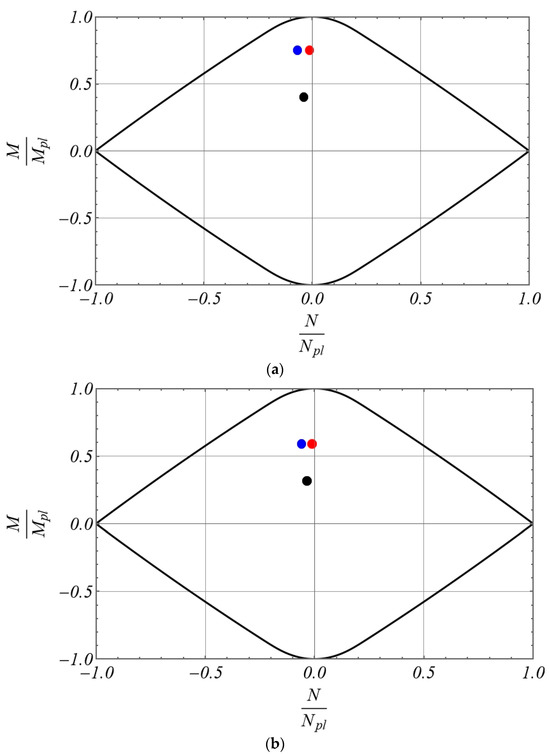
Figure 7.
Yield domains (black point element AC, red point element AB, blue point element BD): (a) frame made of HEB 220 profiles; (b) frame made of HEB 240 profiles.
As described in Section 2, to perform the first step of the proposed design strategy it is necessary to preliminarily assign width and depth of the cross-section beam elements. With the aim of determining the minimum volume structure, the width and depth of the HEB220 are assigned and, with the previously introduced symbols, the results are: and . Furthermore, the web thickness of all the beam elements is assigned as the one of the HEB220 to ensure sufficient shear resistance and that the cross-sections belong to Class 1.
Once all the input data are assigned, problems (3)–(9) were solved by utilizing the FindMinimum command in Mathematica® 14.0 environment, obtaining the optimal thicknesses reported in Table 1 and the related (minimum) volume m3, which determines a volume percentage reduction . The time for conducting the proposed optimization procedures with a HP Intel Core i7-10700 CPU @2.90GHz equipped with 16 GB RAM is less than 2 s. It is easy to observe that even the volume of the structure realised with HEB220 turns out to be greater than the obtained optimal one ( m3).

Table 1.
Results of the optimal design in the first step (dimensions in mm).
To validate the soundness of the first step optimal structure, an elastic plastic analysis has been carried out for the load combinations previously defined (SLS and ULS) by means of nonlinear static analyses by using the by using a research purpose non commercial version of the software HISTRA. According to the load combinations, the frame is subjected firstly to the vertical load distribution, , and then the horizontal nodal forces are applied cyclically where is the load multiplier varying according to the cyclic sequence shown in Figure 8. The incremental analysis has been conducted by dividing each multiplier load segment into 10 steps. The modelling strategy of the frame is based on the FSDB beam element (see Section 3) that allows the simulation of the inelastic behaviour of the columns and beam elements introducing discontinuities corresponding to the abscissae as determined by the proposed design procedure.
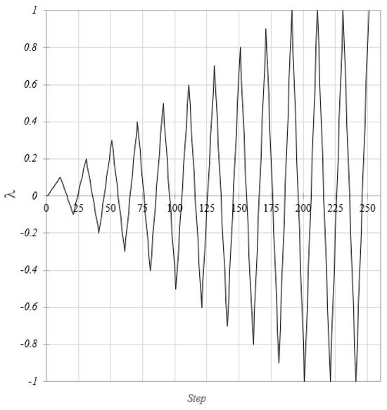
Figure 8.
Load multiplier history adopted in the cyclic analyses.
The results confirm that all the imposed constraints are fulfilled, namely the maximum horizontal drift in SLS conditions being and the stress field on all the beam elements always being within the relevant cross-section yield domain in ULS conditions. The latter statement has been strictly verified for the most stressed cross-sections of the columns and of the beam, and in Figure 9 the yield domains of the cited cross-sections are reported together with the points indicating the acting stress field in ULS conditions.
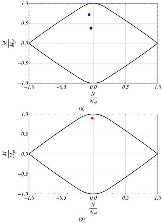
Figure 9.
Yield domains of columns and beam for the frame designed in the first step: (a) common yield domain of the columns, where the black point indicates the more stressed cross-section of the left column, the blue point indicates the more stressed cross-section of the right column; (b) yield domain of the beam, where the red point indicates the more stressed cross-section of the beam.
Once the first step optimal design has been obtained, the second step is performed by solving problems (12)–(17). The geometrical input data are the following:
- ;
- ;
- ;
- ;
- ;
- ;
- .
The solution to problems (12)–(17) provides the optimal thicknesses of all the beam element portions and the optimal width of each weak portion, as reported in Table 2. Furthermore, the resulting frame volume is It is worth noting that the optimal structure is anyway characterised by an overall volume smaller than the initial one , but possesses the desired kinematical and mechanical features.

Table 2.
Results of the second step optimal design (dimensions in mm).
To evidence the soundness of the final optimal design and to verify the fulfilment of all the imposed constraints, again an elastic plastic analysis has been carried out for the load combinations previously defined (SLS and ULS) utilising the same approach as previously described.
At first, in SLS conditions, it has been verified that the required maximum horizontal drift results and that the overall behaviour of the structure remains within the elastic domain, as it can easily be deduced by observing Figure 10 where the diagram is reported, with being the quasi-static cyclic load multiplier .
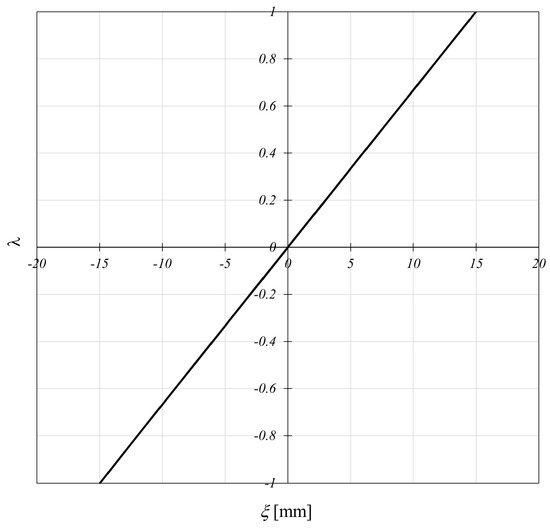
Figure 10.
Load-displacement diagram in SLS conditions of the proposed frame.
Furthermore, in ULS conditions it has been verified that the constraints on the undesired brittle failure are respected, as well as the virtuous trend of the structure to exhibit ductility behaviour. Therefore, in Figure 11, the elastic domains of the cross-sections in corresponding to the welded connections are reported together with the points indicating the acting stress field in ULS conditions. The examination of the results in this figure clearly confirms that the optimal structure safely behaves also against brittle failure since the points lie within the elastic domain. In Figure 12, the diagram is reported for the load combination pointing out the elastic plastic behaviour of the optimal structure. It is worth noting that both the frames constituted by HEB220 or HEB240 cross-sections always behave elastically, i.e., they take no advantage of the ductility properties of the material, as evidenced in Figure 13.
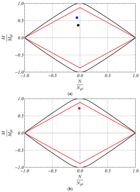
Figure 11.
Dimensionless results for the frame designed in the second step in ULS conditions (black line, yield domain; red line, elastic domain of the end sections): (a) black point, element AC; blue point, element BD; (b) red point, element AB.
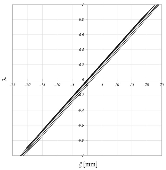
Figure 12.
Load-displacement diagram in ULS conditions of the proposed frame.
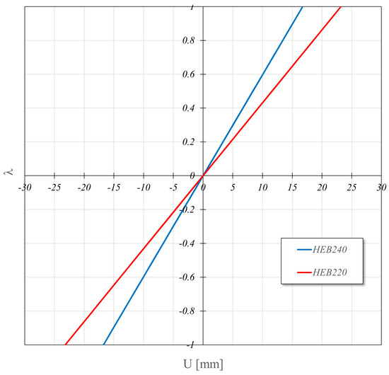
Figure 13.
Response to cyclic loads of frame equipped with a standard profile available on the market.
5. Conclusions
The paper has been devoted to the proposition of a new special iterative approach to design steel frames constituted by I-shaped multi-stepped profiles. It has been proved that the utilisation of these special beam elements allows the designing of frames able to meet all the standard requirements together with further constraints: protection against undesired brittle failure is ensured, and, contextually, the virtuous ductility feature of the material is appropriately used.
In order to perform the numerical application, due to the particular geometry of the beam elements proposed, an extension of the Fibre Smart Displacement-Based (FSDB) beam element model has been proposed. Appropriate elastic plastic analyses have been carried out confirming the effectiveness and the affordability of the presented approach.
On the basis of the obtained results, it can be stated that a considerable cost saving is achieved, equal to 15% with respect to the standard design, and that a sufficient amount of plastic dissipation is involved, equal to 30.4 kN mm, this result certainly being relevant if compared to the purely elastic behaviour exhibited by the standard design.
Further applications are expected to evaluate the volume saving and the dissipation capacity for more complex structures subjected to seismic load conditions, always ensuring the special imposed requirements, even taking into account the analysis of the connections among the beam elements.
Other further studies will be devoted to analysing the technological problem related to the production of the proposed multi-stepped beam elements, performing appropriate cost benefit analysis, placing trust in the continuous technological growth for the effective application of the method.
Author Contributions
Conceptualization, S.B., S.C. and L.P.; software, B.P. and D.R.; validation, B.P., D.R. and S.B.; writing—review and editing, S.B., S.C., L.P., B.P. and D.R. All authors have read and agreed to the published version of the manuscript.
Funding
This research was funded by the Italian Ministry of University and Research (MUR) with the project PRIN2022PNRR P20229YAYL “Safer Architectural Heritage Assets through Risk Assessment—SAHARA project”, Principal Investigator Ivo Caliò.
Data Availability Statement
Data are contained within the article.
Conflicts of Interest
The authors declare no conflicts of interest.
Abbreviations
| coefficients depending on the shape of the yield boundary domain | |
| cross-section width of the columns (left, right) and of the beam | |
| cyclic load multiplier for serviceability limit state conditions | |
| load multiplier for ultimate limit state conditions | |
| material yield stress | |
| cross-section depth of the columns (left, right) and of the beam | |
| stiffness matrix of the generic Gauss cross-section | |
| length of the columns (left, right) and of the beam | |
| number of strips | |
| number of Gauss i-th cross-sections | |
| uniformly distributed dead load | |
| vector of nodal displacements | |
| flange thicknesses of the columns (left, right) and of the beam | |
| web thickness of the columns (left, right) and of the beam | |
| axial displacement function | |
| transversal deflection function | |
| weight of each Gauss point | |
| abscissa of Gauss k-th cross-section | |
| cross-section area of the columns (left, right) and of the beam | |
| area of strip | |
| matrix dependent on the stiffness decay parameters | |
| compatibility matrix | |
| internal stiffness matrix of beam element | |
| internal stiffness matrix of the multi-step beam element | |
| Young’s modulus of the material | |
| cyclic load vector | |
| perfect cyclic loads | |
| moment of inertia of the columns (left, right) and the beam | |
| multi-step element stiffness matrix | |
| axial/transversal displacement shape functions | |
| perfectly clamped generalised elastic stress response vector | |
| vector of nodal forces | |
| Heaviside (unit step) generalised function | |
| volume of the structure | |
| cross-section plastic modulus of columns and beam | |
| normalized variation of the current axial stiffness of the columns and beam segments | |
| normalized variation of the current flexural stiffness of the columns and beam segments | |
| parameters representing the axial plastic state of the k-th Gauss cross-section | |
| parameters representing the flexural plastic state of the k-th Gauss cross-section | |
| vector, dependent on the distance | |
| safety coefficient | |
| coefficient representing the ratio between yield limit bending moment and elastic limit bending moment | |
| axial strain | |
| function for axial/transversal displacement shape functions | |
| maximum admissible horizontal drift | |
| horizontal drift in serviceability limit state conditions | |
| the vectors of nodal displacements | |
| integration constants | |
| functions for the multi-step beam model formulation |
References
- Gokhfeld, D.A.; Cherniavsky, D.F. Limit Analysis of Structures at Thermal Cycling; Springer: Dordrecht, The Netherland, 1980; ISBN 978-90-286-0455-1. [Google Scholar]
- Chen, W.; Duan, L. Plasticity, Limit Analysis, Stability and Structural Design: An Academic Life Journey from Theory to Practice; World Scientific: Singapore, 2021; ISBN 978-981122974-9. [Google Scholar]
- Tabbuso, P.; Spence, S.M.J.; Palizzolo, L.; Pirrotta, A.; Kareem, A. An efficient framework for the elasto-plastic reliability assessment of uncertain wind excited systems. Struct. Saf. 2016, 58, 69–78. [Google Scholar] [CrossRef]
- Marti, K. Limit load and shakedown analysis of plastic structures under stochastic uncertainty. Com. Meth. App. Mech. Eng. 2008, 198, 42–51. [Google Scholar] [CrossRef]
- Benfratello, S.; Di Paola, M.; Palizzolo, L.; Tabbuso, P. Evaluation of the shakedown limit load multiplier for stochastic seismic actions. Meccanica 2017, 52, 2735–2750. [Google Scholar] [CrossRef]
- Banichuk, N.V. Introduction to Optimization of Structures; Springer: New York, NY, USA, 1990; ISBN 978-1-4612-7988-4. [Google Scholar] [CrossRef]
- Benfratello, S.; Palizzolo, L.; Tabbuso, P. Optimization of structures with unrestricted dynamic shakedown constraints. Struct. Multidiscip. Optim. 2015, 52, 431–445. [Google Scholar] [CrossRef]
- Palizzolo, L.; Caffarelli, A.; Tabbuso, P. Minimum volume design of structures with constraints on ductility and stability. Eng. Struct. 2014, 68, 47–56. [Google Scholar] [CrossRef]
- Benfratello, S.; Giambanco, F.; Palizzolo, L.; Tabbuso, P. Structural design of frames able to prevent element buckling. In Proceedings of the 11th International Conference on Computational Structures Technology, CST 2012, Civil-Comp Proceedings, Dubrovnik, Croatia, 4–7 September 2012; Volume 99, ISBN 978-190508854-6. [Google Scholar]
- Benfratello, S.; Giambanco, F.; Palizzolo, L.; Tabbuso, P. Optimal design of steel frames accounting for buckling. Meccanica 2013, 48, 2281–2298. [Google Scholar] [CrossRef]
- Palizzolo, L.; Benfratello, S.; Tabbuso, P. Discrete variable design of frames subjected to seismic actions accounting for element slenderness. Comput. Struct. 2015, 147, 147–158. [Google Scholar] [CrossRef]
- Benfratello, S.; Palizzolo, L.; Tabbuso, P. Optimal design of elastic plastic frames accounting for seismic protection devices. Struct. Multidiscip. Optim. 2014, 49, 93–106. [Google Scholar] [CrossRef]
- Hu, S.; Zhu, S. Life-cycle benefits estimation for hybrid seismic-resistant self-centering braced frames. Earthq. Eng. Struct. Dyn. 2023, 52, 3097–3119. [Google Scholar] [CrossRef]
- Hu, S.; Wang, W.; Shahria Alam, M.; Ke, K. Life-cycle benefits estimation of self-centering building structures. Eng. Struct. 2023, 284, 115982. [Google Scholar] [CrossRef]
- Zhang, R.; Hu, S. Optimal design of self-centering braced frames with limited self-centering braces. J. Build. Eng. 2024, 88, 109201. [Google Scholar] [CrossRef]
- Hu, S.; Lei, X. Machine learning and genetic algorithm-based framework for the life-cycle cost-based optimal design of self-centering building structures. J. Build. Eng. 2023, 78, 107671. [Google Scholar] [CrossRef]
- Nassiraei, H.; Arab, M. Compressive load capacity of CHS X-joints: The Efficacy of doubler plates. Mar. Struct. 2024, 97, 103638. [Google Scholar] [CrossRef]
- Momenzadeh, S.; Kazemi, M.T.; Asl, M.H. Seismic performance of reduced web section moment connections. Int. J. Steel Struct. 2017, 17, 413–425. [Google Scholar] [CrossRef]
- Shakeri, K.; Akrami, V.; Moradpour, S.; Khedmati, S. Post-earthquake Behavior of Steel Moment Resisting Frames with Connections Modified by Introducing Reduced Beam Section (RBS). Int. J. Steel Struct. 2024, 24, 462–476. [Google Scholar] [CrossRef]
- Benfratello, S.; Palizzolo, L. Limited resistance rigid perfectly plastic hinges for steel frames. Intern. Rev. Civ. Eng. 2017, 8, 286–298. [Google Scholar] [CrossRef]
- Benfratello, S.; Cucchiara, C.; Palizzolo, L.; Tabbuso, P. Fixed strength and stiffness hinges for steel frames. In Proceedings of the AIMETA 2017—23rd Conference of the Italian Association of Theoretical and Applied Mechanics, Salerno, Italy, 4–7 September 2017; Feo, L., Ascione, L., Berardi, V.P., Fraternali, F., Tralli, A.M., Eds.; Gechi Edizioni: Mediglia, Italy, 2017; pp. 1287–1296, ISBN 978-889424847-0. [Google Scholar]
- Benfratello, S.; Palizzolo, L.; Tabbuso, P.; Vazzano, S. On the post elastic behavior of LRPH connections. Int. Rev. Model. Simul. 2019, 12, 341–353. [Google Scholar] [CrossRef]
- Palizzolo, L.; Benfratello, S.; Tabbuso, P.; Vazzano, S. Numerical validation of LRPH behaviour by fem analysis. In Advances in Engineering Materials, Structures and Systems: Innovations, Mechanics and Applications, Proceedings of the 7th International Conference on Structural Engineering, Mechanics and Computation, Cape Town, South Africa, 2–4 September 2019; CRC Press/Balkema: Boca Raton, FL, USA, 2019; pp. 1224–1229. [Google Scholar] [CrossRef]
- Benfratello, S.; Palizzolo, L.; Tabbuso, P.; Vazzano, S. LRPH device optimization for axial and shear stresses. Intern. Rev. Civ. Eng. 2020, 11, 152–163. [Google Scholar] [CrossRef]
- Benfratello, S.; Caddemi, S.; Palizzolo, L.; Pantò, B.; Rapicavoli, D.; Vazzano, S. Smart beam element approach for lrph device. In Proceedings of the 24th Conference of the Italian Association of Theoretical and Applied Mechanics, AIMETA 2019, Rome, Italy, 15–19 September 2019; Lecture Notes in Mechanical Engineering. Carcaterra, A., Graziani, G., Paolone, A., Eds.; Spinger: Cham, Switzerland, 2019; pp. 197–213. [Google Scholar] [CrossRef]
- Benfratello, S.; Caddemi, S.; Palizzolo, L.; Pantò, B.; Rapicavoli, D.; Vazzano, S. Targeted steel frames by means of innovative moment resisting connections. J. Constr. Steel Res. 2021, 183, 106695. [Google Scholar] [CrossRef]
- Benfratello, S.; Palizzolo, L.; Vazzano, S. A New Design Problem in the Formulation of a Special Moment Resisting Connection Device for Preventing Local Buckling. J. Appl. Sci. 2022, 12, 202. [Google Scholar] [CrossRef]
- Benfratello, S.; Palizzolo, L. Prevention of brittle failure for steel connections utilizing special devices. Structures 2024, 62, 106153. [Google Scholar] [CrossRef]
- EN 1998-3:2005; Eurocode 8: Design of Structures for Earthquake Resistance—Part 3: Assessment and Retrofitting of Buildings. Comité Européen de Normalisation: Bruxelles, Brussels, 2005.
- EN 1993-1-8:2006; Eurocode 3: Design of Steel Structures Part 1–8: Design of Joints. European Committee for Standardization: Bruxelles, Brussels, 2006.
- DM 17/01/2018; Italian Ministry of Infrastructure and Transport, National Standard. 2018. Available online: https://www.gazzettaufficiale.it/eli/id/2008/02/04/08A00368/sg (accessed on 4 July 2024).
- Pantò, B.; Rapicavoli, D.; Caddemi, S.; Caliò, I. A smart displacement based (SDB) beam element with distributed plasticity. Appl. Math. Model. 2017, 44, 336–356. [Google Scholar] [CrossRef]
- Pantò, B.; Rapicavoli, D.; Caddemi, S.; Caliò, I. A fibre smart displacement based (FSDB) beam element for the nonlinear analysis of reinforced concrete members. Intern. J. Non-Linear Mech. 2019, 117, 103222. [Google Scholar] [CrossRef]
Disclaimer/Publisher’s Note: The statements, opinions and data contained in all publications are solely those of the individual author(s) and contributor(s) and not of MDPI and/or the editor(s). MDPI and/or the editor(s) disclaim responsibility for any injury to people or property resulting from any ideas, methods, instructions or products referred to in the content. |
© 2024 by the authors. Licensee MDPI, Basel, Switzerland. This article is an open access article distributed under the terms and conditions of the Creative Commons Attribution (CC BY) license (https://creativecommons.org/licenses/by/4.0/).