Article

Spall Repair Patch Health Monitoring System Using BIM and IoT

by
Chaehyeon Kim
1,
Junhwi Cho
2,
Jinhyo Kim
3,
Yooseob Song
4,
Julian Kang
5 and
Jaeheum Yeon
2,*
1
Department of Quality Control, GK Tech, Chuncheon 24210, Republic of Korea
2
Department of Regional Infrastructure Engineering, Kangwon National University, Chuncheon 24341, Republic of Korea
3
BIM Design Team, Dong Myeong Engineering Consultants, Seoul 05203, Republic of Korea
4
Department of Civil and Environmental Engineering, University of Alabama in Huntsville, Huntsville, AL 35899, USA
5
Department of Construction Science, Texas A&M University, College Station, TX 77843, USA
*
Author to whom correspondence should be addressed.
Buildings 2024, 14(6), 1589; https://doi.org/10.3390/buildings14061589
Submission received: 8 May 2024 / Revised: 20 May 2024 / Accepted: 27 May 2024 / Published: 31 May 2024

Abstract

Concrete infrastructure is vulnerable to damage such as spalling. Spalling leads to chloride penetration, which causes internal corrosion, weakens structural stability and durability, and increases the likelihood of additional cracks or damage, consequently necessitating repair. Existing repair methods do not consider the factors that affect damage in the repaired areas, so additional damage can occur, making monitoring necessary to identify these factors. Nevertheless, existing studies have not adequately addressed the monitoring of internal conditions within concrete, making it difficult to manage such damage effectively. Accordingly, in this study, a monitoring system was developed using building information modeling (BIM) and the Internet of Things (IoT) to better identify internal changes in concrete pavements. Employing embedded sensors to measure temperature, humidity, and stress within the concrete, our system uses Dynamo scripts for real-time data visualization within BIM. Validated against the ASTM D8292 standard, this system captures and analyzes environmental impacts on concrete. This integration facilitates the detection of internal changes, allowing for the real-time visualization of these impacts. This study can help establish repair plans by identifying factors affecting concrete, contributing to preventive maintenance, potentially reducing maintenance costs, and enhancing the sustainability of concrete infrastructures.

1. Introduction

Concrete is a preferred material in road construction due to its superior strength and relatively low maintenance costs [1,2]; however, concrete pavements are vulnerable to various forms of deterioration over time [3,4]. These include the impacts of climatic changes, physical wear and tear, and chemical interactions, leading to a wide range of pavement damage [5] such as cracks, scaling, spalling, pop-outs, blowups, joint deteriorations, water bleedings, longitudinal joint seal damages, and patch deteriorations [6]. Among these, spalling is of particular concern as it can affect not only the surface of the road but also its structural integrity [7]. Spalling can pose a direct threat to the safety of road users, and this risk is exacerbated by frequent usage and environmental factors [7]. Additionally, if not detected in the early stages, spalling can evolve into more extensive deterioration, making early detection and proper repair crucial [8,9]. Addressing damage such as spalling through effective maintenance strategies is essential for significantly extending the operational lifespan of concrete pavements. These strategies play a pivotal role in reducing repair costs and minimizing disruptions to road users [10]. Proactively attending to maintenance needs can greatly enhance the longevity and performance of pavement infrastructure [11]; thus, addressing spalling through repair measures is critical within the broader maintenance strategy.
Two of the most representative techniques for addressing spalling are the throw-and-go patch and partial-depth repair methods [12]. The throw-and-go patch method, for instance, serves as a temporary and urgent solution, employing asphalt as a repair material to promptly fill the damage caused by spalling [13]. However, the repair material is not identical to the material of the existing substrate when the throw-and-go patch method is applied [13]. Therefore, when the surface of the concrete pavement repeatedly contracts and expands due to temperature changes, the adhesive strength of the interface between the asphalt patch and the spalling is reduced [14]. As it weakens, the asphalt patch eventually separates from the spalling [15]. The partial-depth repair method, also known as the spall repair patch, is a frequently adopted method due to its seamless integration with the pre-existing substrate. This approach entails the utilization of repair materials that match the composition of the initial concrete surface [16]. However, even if the repair material is identical to the existing concrete pavement, the concrete patch can be damaged again for unknown reasons. Currently, the cause of damage is assumed to be the weakening of adhesion due to the difference in the material properties of the existing substrate and the repair material, the difference in the coefficient of thermal expansion, and the influence of moisture penetrating the adhesion interface [17]. However, since these are comprehensive assumptions as to the causes of damage, it is not easy to determine which cause has a crucial influence on the damage occurring in the repaired area, leading to challenges in pavement preventive maintenance. Furthermore, determining the primary cause of the damage is difficult because it is indetectable to the naked eye until visible in the repaired area.
Therefore, studies are currently being conducted to monitor the condition of concrete using continuously evolving technologies.
Sakr and Sadhu [18] proposed a method to improve the real-time monitoring of aging infrastructure by integrating building information modeling (BIM) and the Internet of Things (IoT). They leveraged a Dynamo-based framework for laboratory-scale bridge and building models to automatically collect and analyze acceleration data and visualize them within BIM, solving the problem of manual data linking, thus reducing the need for human intervention and improving data processing capabilities.
Scianna et al. [19] integrated BIM and IoT sensors to monitor structural behavior in real time. They developed a bridge beam model that enables real-time deflection simulations in a laboratory environment using a low-cost sensor system consisting of distance sensors, Arduino Uno, Wi-Fi transmission modules, and BIM 2023 software. This model enables the monitoring of construction projects that has not traditionally been addressed after the design phase and demonstrates how to visualize real-time data within BIM.
Chang et al. [20] proposed the integration of BIM and IoT to enhance decision support in facility management. To support the decision-making process, they developed a platform to visualize environmental conditions within BIM using sensor data and applied this platform in a university campus environment to measure real-time data from various sensors for different scenarios such as energy conservation and audience distribution in auditoriums. They show how data can be visualized in BIM, and their platform leverages Dynamo for automated data capture and visualization, demonstrating the potential of this integration to improve the facility’s management and operational efficiency through a better visualization of sensor data and more informed decision-making.
Oreto et al. [21] developed a BIM tool designed to optimize urban road maintenance. By integrating various data sources, such as road geometry, traffic, and pavement condition, into the BIM environment, the possibility of creating efficient maintenance plans allows practitioners to systematically assess pavement conditions, predict future deterioration, and select appropriate maintenance interventions. This research can improve the efficiency and sustainability of road maintenance operations by integrating advanced recycling technologies and secondary raw materials.
Sofia et al. [22] proposed a digital twin platform for bridge monitoring and maintenance for the Mohammed VI Bridge in Morocco. In their paper, based on a point cloud scanned through a mapping solution, a digital twin model was created using the Leica CloudWorx plugin and then integrated with the 3D city model environment, bridge survey information, and IoT sensors.
Isailović et al. [23] utilized a Bridge Information Model (BrIM) that integrates damage components into BIM through point cloud-based spalling detection and IFC models. In their study, the shape and characteristics of the detected damage were visualized in the BrIM by first extracting the damage from the point cloud obtained using a UAV through image-based multi-view classification and mapping the image segment depicting the damage to the damaged site. Their study aimed to contribute to the use of digital twins to manage future deployment environments.
Kang et al. [24] introduced multimedia knowledge-based bridge condition monitoring using digital twins. Based on the small amount of data collected using the sensors of the real system, the situation was analyzed through various simulations in the digital twin model, and the optimal time for maintenance was predicted and applied to the actual bridge. The simulation consists of scenarios such as obtaining displacement and stress values of members using temperature, wind direction, wind speed, and other factors such as input data or obtaining the load applied to the bridge by converting the acceleration data into natural frequencies after collecting them.
Previous studies, summarized in Table 1, present techniques for identifying the condition of structures using BIM-based monitoring technology. However, these studies primarily focus on assessing the extent of damage in concrete pavements after it has occurred, rather than identifying the internal condition of concrete. Consequently, this approach fails to pinpoint internal changes in concrete due to environmental influences. If internal changes in concrete can be identified, it will be easier to analyze factors affecting concrete, making it possible to select appropriate repair materials when damage occurs in the future. To address this challenge, this study aims to develop a monitoring system using BIM and the IoT to better identify internal changes in concrete pavements, thereby confirming the system’s ability to accurately identify the factors influencing concrete and increase its sustainability. This study employs several embedded sensors to measure temperature, humidity, and stress within the concrete, leveraging Dynamo scripts for real-time data visualization within BIM. This system is validated against the ASTM D8292 standard to ensure its accuracy and reliability in capturing and analyzing environmental impacts on concrete. This integration facilitates the detection of internal changes, enabling the real-time visualization of environmental impacts on concrete. The findings can assist in establishing repair plans by identifying factors affecting concrete, contributing to preventive maintenance, potentially reducing maintenance costs, and enhancing the sustainability of concrete infrastructures. Following this introduction, Section 2 presents the detailed methodology, including the design and implementation of the monitoring system. Section 3 discusses the validation process and results. Section 4 elaborates on the findings and their implications for concrete pavement maintenance. Finally, Section 5 concludes the paper, summarizing the contributions and suggesting directions for future research.

2. Materials and Methods

The entire framework of the monitoring system proposed in this research encompasses a comprehensive process, from data measurement using sensors to visualization, as shown in Figure 1. Initially, the system involves embedding temperature and humidity sensors, along with a load cell, into concrete. This setup is designed to measure variations in temperature, humidity, and stress within the concrete. The data collected from these measurements are then wirelessly transmitted from the site to indoor facilities via a microcontroller [25]. Subsequently, in the visualization phase, fluctuations in the transmitted temperature, humidity, and load data are rendered visible using Autodesk Revit [20]. Due to the limitations of commercial BIM software in directly visualizing sensor-measured data, the use of visual programming software is essential to enable visualization [26]. This proposed system effectively facilitates the monitoring of concrete road pavement conditions at repair sites through the integration of BIM and IoT sensors. This allows for the measurement and management of changes resulting from external stimuli, such as passing vehicles at the repair site, by illustrating them in a 3D concrete patch model within a digital environment. To achieve this, scripts for visualizing IoT-measured data in BIM were developed using Dynamo 2.13.1.3891, a visual programming tool of Revit 2023.

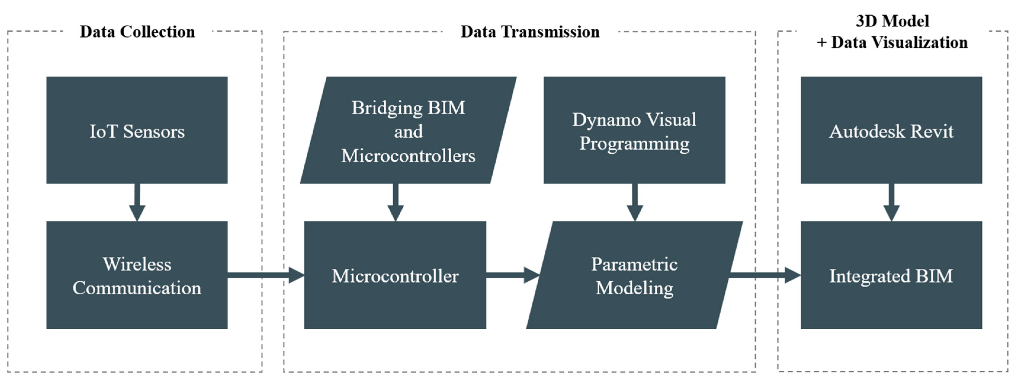
2.1. Monitoring System

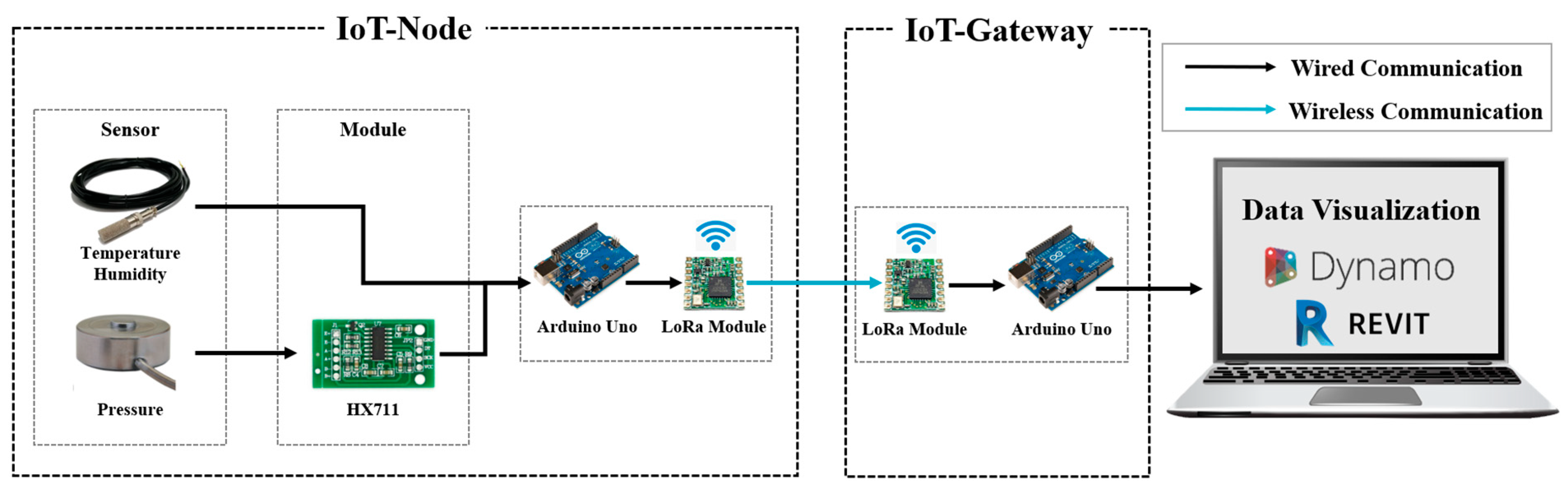
2.1.1. Monitoring System Configuration
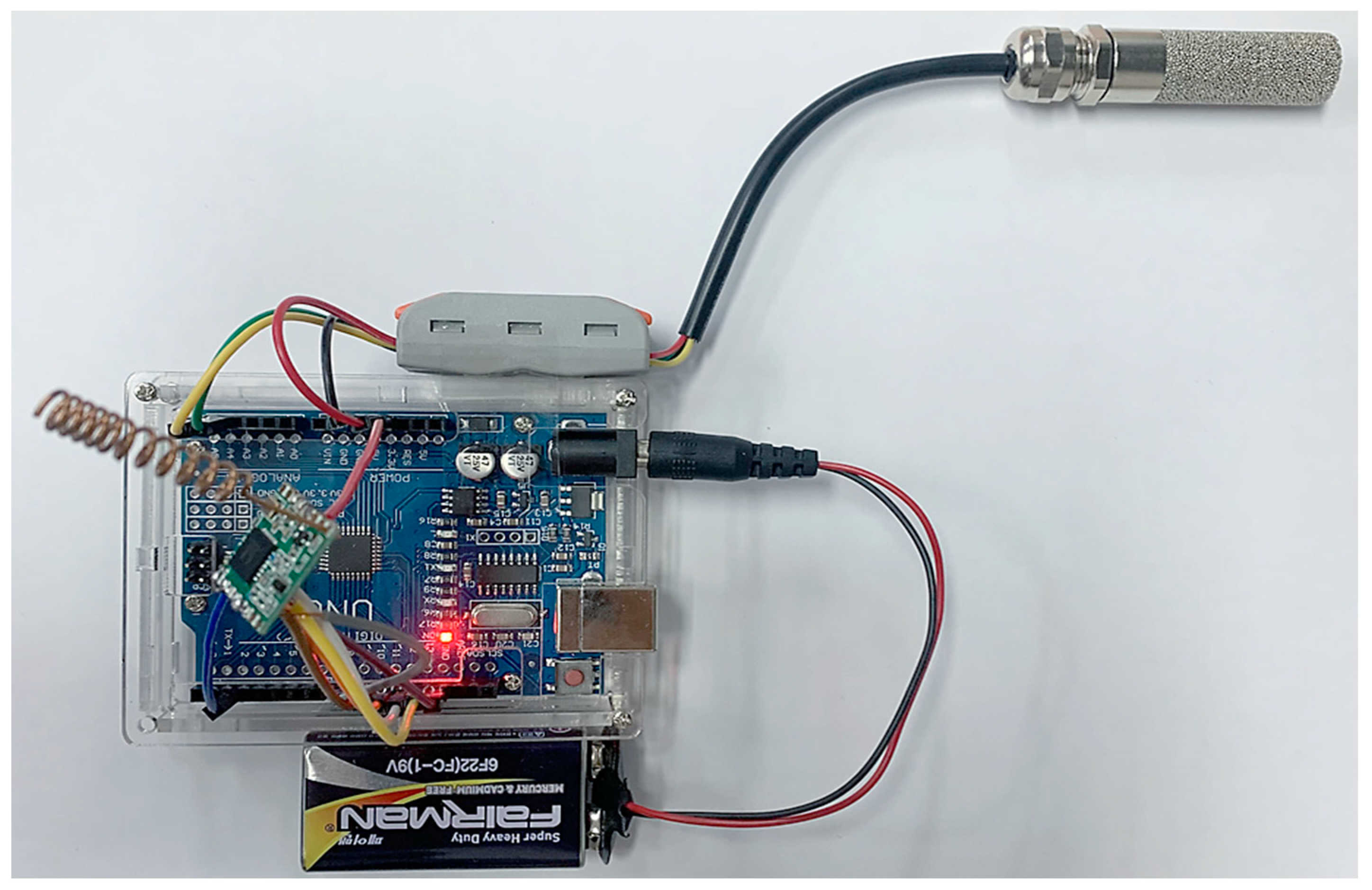
To implement data transmission and reception for monitoring temperature, humidity, and stress changes, the IoT system is composed of a temperature and humidity sensor, load cell, Arduino board, communication conversion module HX711 [27], and a LoRa-based wireless communication module, as shown in Figure 2. The IoT devices in the proposed monitoring system are classified into two groups: IoT-Node and IoT-Gateway. The IoT-Node is embedded in the concrete repair site to collect temperature, humidity, and stress measurement data from within the concrete. In contrast, the IoT-Gateway receives the data measured from the IoT-Node in real time and transmits it to the monitoring system.
In this research, the Arduino Uno [28], the most widely used and easily programmable among Arduino boards, was utilized. A total of six Arduino Unos were employed to set up the IoT-Node and IoT-Gateway: the key components of the IoT device. However, the Arduino Uno does not inherently support wireless communication, thus requiring an external wireless communication module for completion [29]. Therefore, this study employed the SX1276 [30], a LoRa-based wireless communication module that is compatible with Arduino Uno, supports the I2C serial communication protocol, and provides open source libraries for Arduino, enabling data transmission.
In the IoT-Node, one Arduino Uno is connected to each temperature–humidity sensor and load cell, collecting measured data. The gathered data are then sent to the Arduino Uno with a connected LoRa module in the IoT-Gateway. This Arduino Uno is programmed to output the same data received by the Arduino Uno with the LoRa module. As a result, a total of four Arduino boards were used for the delivery of temperature, humidity, and stress measurement data, with Dynamo being connected using two boards. This configuration allows both software to simultaneously process temperature, humidity, and stress measurement data through communication with the connected boards.

2.1.2. Sensors

The SHT-31 humidity–temperature sensor from Sensirion [31] and the Model 53 load cell from Honeywell [31] were used to measure the physical quantities of temperature, humidity, and stress within the damaged areas. To ensure the cost-effectiveness of the monitoring system, the SHT-31 and Arduino Uno were utilized. While the SHT-31 is a chip-type sensor released in a DFN-8 package, a probe-type sensor with an internal waterproof coating was used to prevent short circuits due to moisture and to extend its lifespan during concrete embedding. The specifications of the SHT-31 are shown in Table 2, and the circuit connection with the Arduino Uno is shown in Figure 3.
The Model 53, used for stress measurement, is a button-type strain gauge-based load cell with an output voltage of 2 mV/V and a maximum load range of 50,000 lb [32]. A strain gauge-based load cell generally outputs a low voltage, necessitating the usage of a voltage amplifier [33]; thus, the HX711 module, which includes a high-precision 24-bit A/D converter chip and a voltage amplification circuit, was employed. When physical force is applied to the Model 53, the electrical signal passes through the amplification circuit and is delivered to the HX711 chip. The received electrical signal is converted into a digital signal and transmitted to the upper device, the Arduino Uno. The specifications of the Model 53 are shown in Table 3, and the circuit was connected as shown in Figure 4, following the design method suggested by Al-Mutlaq and Wende [34].

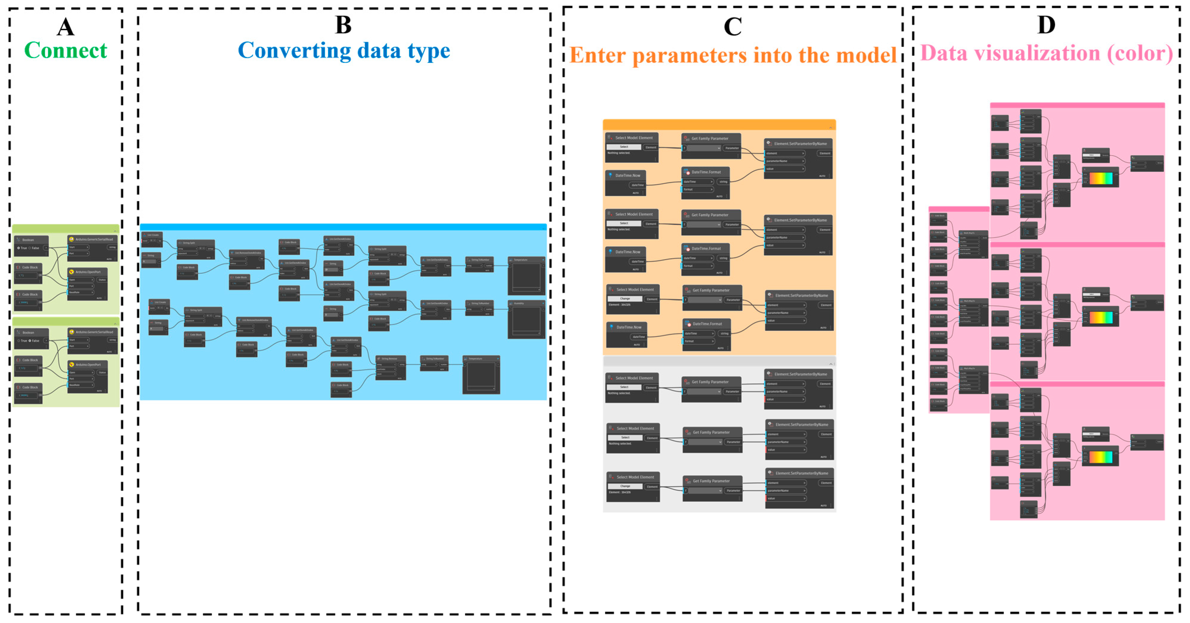
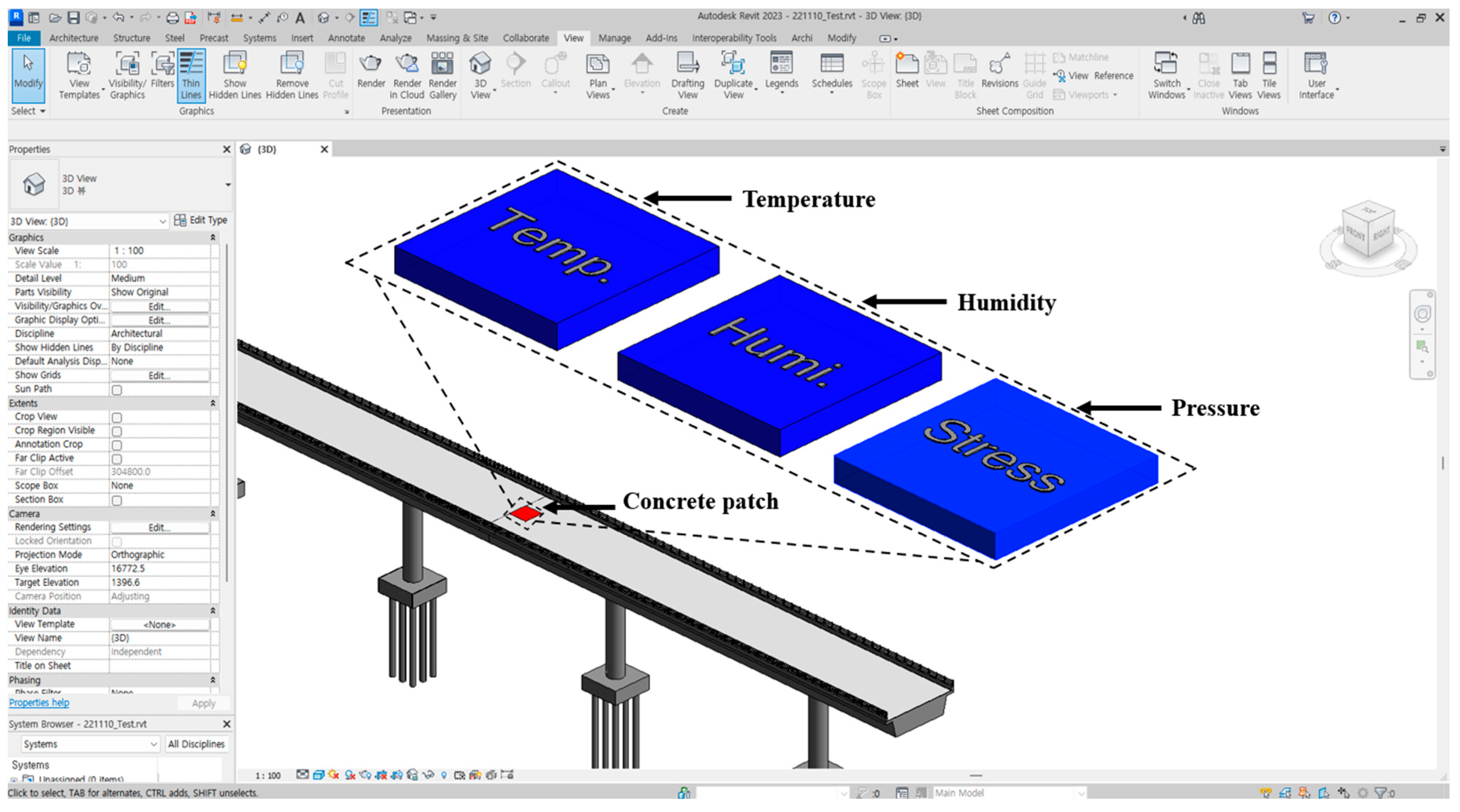
2.2. Development of Dynamo Scripts for Data Visualization

Although BIM can visualize specific structures with a 3D model and store attribute information, it cannot receive data measured via sensors. Consequently, in this study, Dynamo, a visual programming software, was used to develop scripts for visualizing the data collected from the IoT sensors in a commercial BIM program. Autodesk Revit was used for BIM creation. Among commercial BIM programs such as Bentley, Civil 3D, and Revit, Revit was chosen because of its high compatibility with Dynamo and its widespread use. These developed scripts allow for temperature, humidity, and stress data transmitted from the Arduino Uno to be applied to a 3D model within Autodesk Revit, thus visualizing changes through color. The developed scripts consist of four node groups, as shown in Figure 5.
Group A connects the Arduino Uno microcontroller and Dynamo using the Firefly [35] library node. To accomplish this, the Firefly library node enables serial communication between Dynamo and the two Arduino Unos, each connected to the temperature–humidity sensor and the load cell. When the Arduino Uno is connected to a PC via a USB cable, it communicates by converting the signal to the Recommended Standard 232 (RS232) serial communication standard, which is represented as a serial port rather than the USB communication standard [36]. Therefore, since each Arduino board connected to the PC is assigned a unique serial port number, the port number was set in the Arduino IDE to transmit data to Dynamo, allowing for the measurement data from the temperature–humidity sensor and load cell to be received.
Group B contains nodes where the data received from the Arduino Uno are converted to a format that can be used in Dynamo. Since the received data are delivered in string format, it must be converted into numerical format. In this process, the string-formatted data are therefore broken down into a form corresponding to temperature, humidity, and stress data and converted into real numbers.
Group C contains nodes that select parameters of a 3D model created in Revit and can input the attribute information required by the user. This group converts the temperature, humidity, and stress data and the current time and date into real numbers to be inserted into the parameters (temperature, humidity, and stress) of the 3D model as attribute information.
Group D, the final group, sets the model to perform 3D visualization, defines colors, and performs 3D data visualization. This group defines colors corresponding to each 3D model representing temperature, humidity, and stress based on a specified color range using RGB elements. In this process, the 3D model created in Revit can visually represent the data measured from the sensor. The BIM used in this study was implemented as shown in Figure 6. This model represents the concrete repair part of an arbitrary concrete bridge structure in 3D, and each of the data processed in node groups A, B, C, and D is connected to visualize the changing environmental variables.
In this study, the decision to symbolically visualize temperature, humidity, and stress in separate models within the BIM framework, rather than combining them into a single model, was to enhance the interpretability and utility of the data. This symbolic visualization allows for a clearer and more precise representation of each environmental factor. In a BIM context where accuracy is essential, this approach significantly reduces the potential for data overlap and confusion. By creating distinct visual models for temperature, humidity, and stress, this study ensures a more effective analysis, crucial for the predictive maintenance and safety assessment of the concrete bridge structure. This methodological choice demonstrates an understanding of the challenges in presenting complex data in a manner that is both clear and symbolically informative to the user.

3. Results and Discussion

3.1. Results

This study focused on three key factors that significantly impact the performance of concrete: temperature, humidity, and stress. Temperature was monitored, considering that damage to concrete is primarily caused by differences in the coefficients of thermal expansion of the existing aggregate. Additionally, humidity levels were monitored, as moisture infiltration in concrete can lead to damage. Furthermore, recognizing impact load as a contributing factor to concrete damage, a load cell was used to measure changes in stress applied to the concrete. In this study, sensors corresponding to these three key factors were embedded in concrete specimens for monitoring, and changes were visualized. To validate the developed monitoring system, the ASTM D8292 standard test method was utilized [37]. This method is primarily focused on assessing the permanent deformation behavior and rutting resistance using a modified loaded wheel tracking test. ASTM D8292, originally devised to evaluate the deformation characteristics and rutting resistance of asphalt mixtures under repeated traffic load conditions, uses a wheel tracking device to simulate vehicular load. Additionally, the tester used in this standard is designed to be sealed and includes an integrated temperature control system, ensuring a consistent testing environment. Although ASTM D8292 is typically associated with asphalt testing, the continuous load and temperature control benefits of the wheel tracking test effectively simulate road conditions, meaning that this approach can be adapted for use with concrete. Based on these considerations, the ASTM D8292 standard was adapted to a concrete specimen with embedded IoT sensors in this study for the purpose of performing the verification of the sensors embedded in the concrete specimen, as shown in Figure 7. During the wheel tracking test process, data were collected and transmitted using an IoT-Node and IoT-Gateway based on the Arduino Uno and LoRa modules. Data measured during the wheel tracking test process can be linked to BIM and IoT sensor data through scripts developed using Dynamo and then applied to the 3D model in Autodesk Revit to visualize changes in color. Among various temperature settings tested, changes in temperature, humidity, and pressure were measured in a test conducted at 40 °C and visualized, as shown in Figure 8. During the wheel tracking test, the embedded sensors accurately measured the temperature, humidity, and stress within the concrete specimen. The collected data were transmitted in real time and integrated into the BIM environment using scripts developed with Dynamo. This integration allowed for the visualization of environmental changes directly within the BIM. As the temperature increased to 40 °C during the test, the corresponding sensors recorded this change, and the BIM reflected these data by changing colors to represent different temperature levels. Similarly, changes in stress and humidity measured by the sensors were visualized within the BIM, enabling a clear and immediate interpretation of the data.

3.2. Discussion

This study aims to develop and validate a monitoring system integrated with BIM and IoT technologies to assess the internal conditions of concrete pavements. The approach involved embedding temperature, humidity, and stress sensors into concrete specimens to monitor changes in these parameters. The results from the monitoring system revealed several significant findings regarding the performance and potential of this integrated approach. The concrete specimen, designed to mimic a spall repair patch, was tested under various temperature settings by continuously applying load using the wheel tracking tester’s internal experimental temperature control function. The data collected during these tests validated the effectiveness of the monitoring system. The sensors accurately measured changes in temperature, humidity, and stress, providing data that could be visualized in real time within the BIM environment. This ability to monitor environmental conditions within the concrete is crucial for understanding the factors that contribute to concrete deterioration [38].
Existing studies have lacked a direct visualization and monitoring approach for the internal conditions of concrete. The integration of BIM with IoT sensors and the use of Dynamo scripts for the real-time visualization of the internal conditions of concrete present significant advancements over traditional monitoring methods. Traditional BIM software has limitations in directly visualizing sensor-measured data, but by leveraging the visual programming tool Dynamo, these limitations were overcome. The developed scripts enabled the seamless integration of real-time sensor data into BIM, allowing for the visualization of temperature, humidity, and stress changes. The visualization within BIM enables stakeholders to interpret and respond to environmental changes more effectively, offering a more intuitive understanding of the state changes within concrete structures [39]. By representing temperature, humidity, and stress data through color-coded 3D models, stakeholders can easily interpret the environmental impacts on the concrete. This facilitates proactive maintenance and repair strategies, potentially reducing long-term maintenance costs and extending the lifespan of concrete pavements. This proactive approach is expected to enhance the durability and sustainability of concrete infrastructure by ensuring that maintenance and repair efforts are both timely and effective.

3.3. Limitations

This study has several limitations. The verification experiments of the monitoring system were performed in a controlled indoor environment using a wheel tracking device with a minimum operating temperature of 30 °C. This indicates a lack of verification for temperatures lower than 30 °C. Concrete in real-world scenarios faces diverse environmental conditions, such as significant temperature variances between day and night, seasonal shifts, and weather-related degradation. However, due to practical challenges in applying these conditions on-site, such as legal and safety issues, this study was confined to indoor settings. Therefore, there is a necessity for further exploration into actual meteorological conditions and practical applications in real-world settings.
Furthermore, the research predominantly focused on three critical elements: temperature, humidity, and stress [40,41,42]. These were chosen based on their primary impact on concrete damage due to differential thermal expansion, moisture penetration, and impact loads. However, additional physical and chemical characteristics, such as pH levels, chloride content, and carbonation depth, could also significantly affect the performance and lifespan of concrete. Therefore, it is necessary to consider these aspects and integrate a wider range of sensors for a more comprehensive analysis.
Additionally, this study’s findings are based on controlled experimental conditions. While these conditions allowed for the precise control and measurement of variables, they may not fully represent the complexity and variability of real-world environments. Future research should aim to validate the monitoring system under more varied and realistic conditions to ensure its robustness and applicability.
Lastly, this study utilized the visual programming tool Dynamo to overcome the limitations of traditional BIM software in visualizing sensor-measured data. While this approach proved effective in this study, the reliance on specific software tools may limit the generalizability of the findings. Exploring alternative tools and methods could enhance the system’s adaptability and usability across different platforms and applications.

4. Conclusions

  • This research focused on the development and validation of a monitoring system for concrete repair areas, integrating BIM and IoT technologies. This study’s findings led to several significant conclusions:
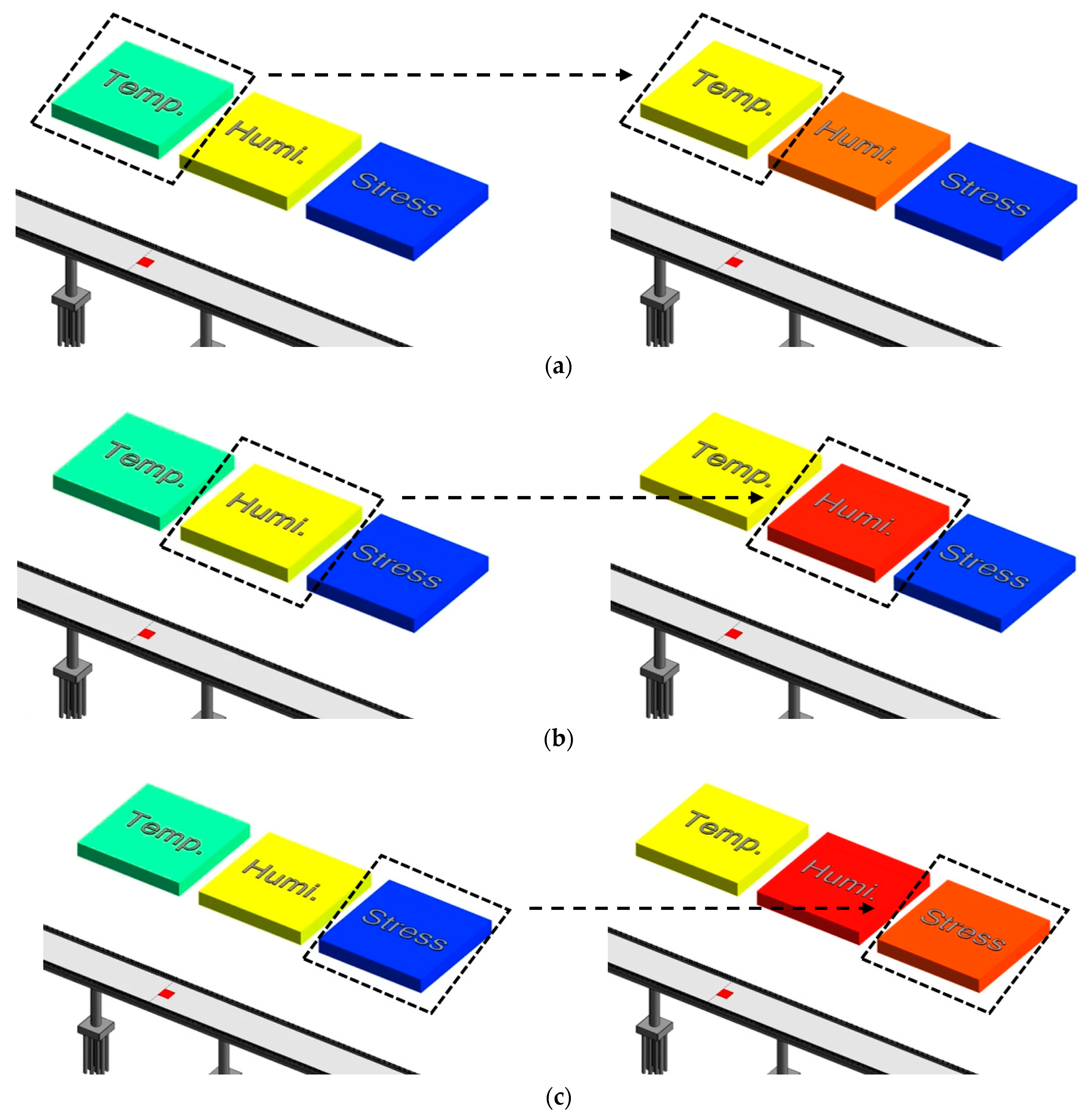
  • The development of the monitoring system facilitated the measurement of temperature, humidity, and stress changes within a concrete repair area. It enabled a deeper understanding of the effects of core factors like temperature, humidity, and stress change within the concrete repair area.
  • The successful integration of BIM and IoT using Dynamo provided data visualization capabilities not previously achievable in traditional BIM software. This integration allowed for the real-time visualization of sensor data within the BIM environment, enhancing the interpretability and utility of the collected data.
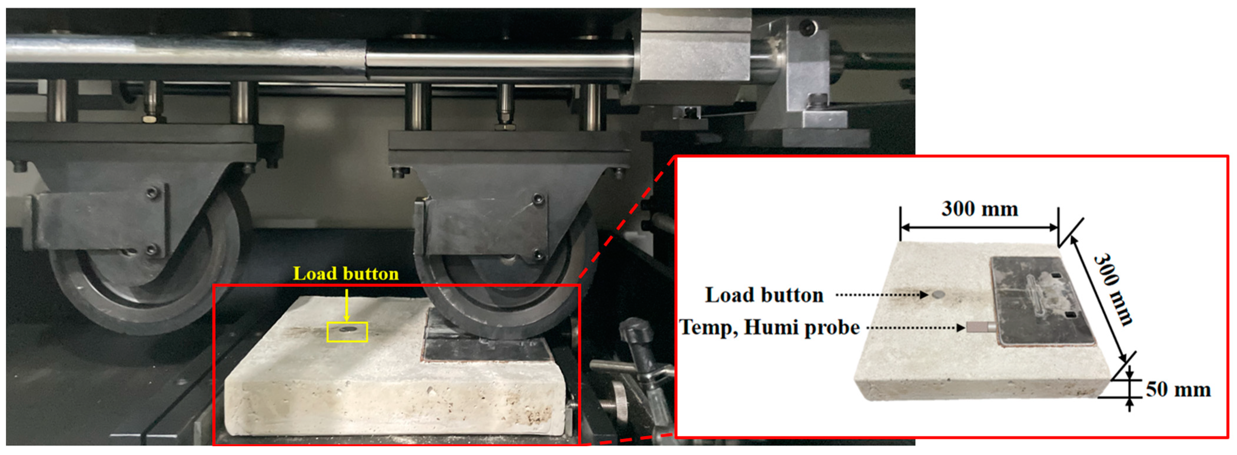
  • The reliability of the proposed monitoring system was validated through an adapted ASTM D8292 experiment. Originally designed for asphalt, this method was adapted to provide a controlled testing environment for concrete specimens, ensuring consistent temperature settings and sustained load conditions. This adaptation enabled the precise verification of the embedded sensors’ performance.
The development of an integrated BIM and IoT monitoring system in this study represents a significant advancement in the field of predictive maintenance for concrete pavements. This innovative approach is expected to extend the lifespan of concrete pavements and reduce the overall costs associated with reactive maintenance, thereby enhancing the sustainability of these structures. Moreover, the methodologies developed in this study have potential applications in maintaining other concrete structures, such as tunnels and bridges, indicating a broader impact beyond pavement roads.
Future research should focus on addressing the identified limitations, such as the need for real-world validation under varied environmental conditions and the integration of additional physical and chemical sensors for a more comprehensive analysis. Additionally, exploring alternative tools and methods to enhance the system’s adaptability and usability across different platforms and applications will be crucial. Expanding the monitoring capabilities to include a wider range of environmental factors will further improve the robustness and applicability of the monitoring system, ultimately contributing to more effective and sustainable concrete infrastructure maintenance strategies.

5. Patents

A patent application for the proposed method has been filed (pending registration) in South Korea: “Electronic Apparatus for Identifying the Cause of Re-Damage of Concrete Based on Digital Twin, and Its System”, Application No.10-2023-0050751, Korean Intellectual Property Office (KIPO), 18 April 2023. Published version of the manuscript.

Author Contributions

Conceptualization, J.Y.; methodology, Y.S.; software, J.K. (Jinhyo Kim); validation, J.K. (Julian Kang); formal analysis, J.C.; investigation, J.C.; resources, C.K.; data curation, C.K.; writing—original draft preparation, C.K.; writing—review and editing, J.C.; visualization, J.K. (Jinhyo Kim); supervision, J.Y.; project administration, J.Y.; funding acquisition, J.Y. All authors have read and agreed to the published version of the manuscript.

Funding

This work was supported by the National Research Foundation of Korea (NRF) grant funded by the Korea government (MSIT) (No. 2021R1F1A10606851222182102130102).

Data Availability Statement

The data supporting this study’s findings are available on request from the authors.

Conflicts of Interest

Authors Chaehyeon Kim and Jinhyo Kim were employed by the companies GK Tech and Dong Myeong Engineering Consultants, respectively. The remaining authors declare that the research was conducted in the absence of any commercial or financial relationships that could be construed as a potential conflict of interest.

References

  1. Behera, M.; Bhattacharyya, S.; Minocha, A.; Deoliya, R.; Maiti, S. Recycled aggregate from C&D waste & its use in concrete–A breakthrough towards sustainability in construction sector: A review. Constr. Build. Mater. 2014, 68, 501–516. [Google Scholar] [CrossRef]
  2. Li, J.; Zhang, W.; Cao, Y. Laboratory evaluation of magnesium phosphate cement paste and mortar for rapid repair of cement concrete pavement. Constr. Build. Mater. 2014, 58, 122–128. [Google Scholar] [CrossRef]
  3. Plati, C. Sustainability factors in pavement materials, design, and preservation strategies: A literature review. Constr. Build. Mater. 2019, 211, 539–555. [Google Scholar] [CrossRef]
  4. Debnath, B.; Sarkar, P.P. Pervious concrete as an alternative pavement strategy: A state-of-the-art review. Int. J. Pavement Eng. 2020, 21, 1516–1531. [Google Scholar] [CrossRef]
  5. Jiang, C.; Gu, X.; Huang, Q.; Zhang, W. Carbonation depth predictions in concrete bridges under changing climate conditions and increasing traffic loads. Cem. Concr. Compos. 2018, 93, 140–154. [Google Scholar] [CrossRef]
  6. Darter, M.I.; Barenberg, E.J.; Yrjanson, W.A. Joint Repair Methods for Portland Cement Concrete Pavements; Transportation Research Board: Washington, DC, USA, 1985. [Google Scholar]
  7. Koch, C.; Georgieva, K.; Kasireddy, V.; Akinci, B.; Fieguth, P. A review on computer vision based defect detection and condition assessment of concrete and asphalt civil infrastructure. Adv. Eng. Inform. 2015, 29, 196–210. [Google Scholar] [CrossRef]
  8. Georgali, B.; Tsakiridis, P. Microstructure of fire-damaged concrete. A case study. Cem. Concr. Compos. 2005, 27, 255–259. [Google Scholar] [CrossRef]
  9. Omar, T.; Nehdi, M.L.; Zayed, T. Infrared thermography model for automated detection of delamination in RC bridge decks. Constr. Build. Mater. 2018, 168, 313–327. [Google Scholar] [CrossRef]
  10. Hüthwohl, P.; Lu, R.; Brilakis, I. Multi-classifier for reinforced concrete bridge defects. Autom. Constr. 2019, 105, 102824. [Google Scholar] [CrossRef]
  11. Frangopol, D.M.; Saydam, D.; Kim, S. Maintenance, management, life-cycle design and performance of structures and infrastructures: A brief review. Struct. Infrastruct. Eng. 2012, 8, 1–25. [Google Scholar] [CrossRef]
  12. Shahin, M.Y. Pavement Management for Airports, Roads, and Parking Lots, 1st ed.; Springer: New York, NY, USA, 1994. [Google Scholar]
  13. McDaniel, R.; Olek, J.; Behnood, A.; Magee, B.; Pollock, R. Pavement Patching Practices; Transportation Research Board: Washington, DC, USA, 2014. [Google Scholar] [CrossRef]
  14. Karimi, H.R.; Khedri, E.; Aliha, M.; Shaker, H.; Haghighatpour, P.J. Repair efficiency evaluation for cracked asphalt mixture pavement in different ambient temperatures using bitumen and polymer concrete as repair materials. Constr. Build. Mater. 2023, 369, 130556. [Google Scholar] [CrossRef]
  15. Wilson, T.P.; Romine, A. Materials and Procedures for Repair of Potholes in Asphalt-surfaced Pavements—Manual of Practice; The National Academies of Sciences, Engineering, and Medicine: Washington, DC, USA, 2001. [Google Scholar]
  16. Banaeipour, A.; Al Sarfin, M.A.; Thomas, R.J.; Maguire, M.; Sorensen, A.D. Laboratory and Field Evaluation of Commercially Available Rapid-Repair Materials for Concrete Bridge Deck Repair. J. Perform. Constr. Facil. 2022, 36, 04022031. [Google Scholar] [CrossRef]
  17. Meddah, M.S.; Bencheikh, M. Properties of concrete reinforced with different kinds of industrial waste fibre materials. Constr. Build. Mater. 2009, 23, 3196–3205. [Google Scholar] [CrossRef]
  18. Sakr, M.; Sadhu, A. Visualization of structural health monitoring information using Internet-of-Things integrated with building information modeling. J. Infrastruct. Intell. Resil. 2023, 2, 100053. [Google Scholar] [CrossRef]
  19. Scianna, A.; Gaglio, G.F.; La Guardia, M. Structure monitoring with BIM and IoT: The case study of a bridge beam model. ISPRS Int. J. Geo-Inf. 2022, 11, 173. [Google Scholar] [CrossRef]
  20. Chang, K.-M.; Dzeng, R.-J.; Wu, Y.-J. An automated IoT visualization BIM platform for decision support in facilities management. Appl. Sci. 2018, 8, 1086. [Google Scholar] [CrossRef]
  21. Oreto, C.; Massotti, L.; Biancardo, S.A.; Veropalumbo, R.; Viscione, N.; Russo, F. BIM-based pavement management tool for scheduling urban road maintenance. Infrastructures 2021, 6, 148. [Google Scholar] [CrossRef]
  22. Sofia, H.; Anas, E.; Faïz, O. Mobile mapping, machine learning and digital twin for road infrastructure monitoring and maintenance: Case study of mohammed VI bridge in Morocco. In Proceedings of the 2020 IEEE International conference of Moroccan Geomatics (Morgeo), Casablanca, Morocco, 11–13 May 2020; pp. 1–6. [Google Scholar] [CrossRef]
  23. Isailović, D.; Stojanovic, V.; Trapp, M.; Richter, R.; Hajdin, R.; Döllner, J. Bridge damage: Detection, IFC-based semantic enrichment and visualization. Autom. Constr. 2020, 112, 103088. [Google Scholar] [CrossRef]
  24. Kang, J.-S.; Chung, K.; Hong, E.J. Multimedia knowledge-based bridge health monitoring using digital twin. Multimed. Tools Appl. 2021, 80, 34609–34624. [Google Scholar] [CrossRef]
  25. Anik, S.M.H.; Gao, X.; Meng, N.; Agee, P.R.; McCoy, A.P. A cost-effective, scalable, and portable IoT data infrastructure for indoor environment sensing. J. Build. Eng. 2022, 49, 104027. [Google Scholar] [CrossRef]
  26. Desogus, G.; Quaquero, E.; Rubiu, G.; Gatto, G.; Perra, C. Bim and iot sensors integration: A framework for consumption and indoor conditions data monitoring of existing buildings. Sustainability 2021, 13, 4496. [Google Scholar] [CrossRef]
  27. Avia Semiconductor (Xiamen) HX711. Available online: http://en.aviaic.com/detail/730856.html (accessed on 1 May 2024).
  28. Arduino Uno Rev3. Available online: https://store.arduino.cc/products/arduino-uno-rev3 (accessed on 1 May 2024).
  29. Margolis, M.; Jepson, B.; Weldin, N.R. Arduino Cookbook: Recipes to Begin, Expand, and Enhance Your Projects, 3rd ed.; O’Reilly Media: Newton, MA, USA, 2020. [Google Scholar]
  30. Semtect Product Details SX1276. Available online: https://www.semtech.com/products/wireless-rf/lora-connect/sx1276 (accessed on 1 May 2024).
  31. Sensirion SHT31-DIS-B. Available online: https://sensirion.com/products/catalog/SHT31-DIS-B (accessed on 1 May 2024).
  32. Honeywell Model 53 Series. Available online: https://sps.honeywell.com/us/en/products/advanced-sensing-technologies/industrial-sensing/industrial-test-and-measurement/load-cells/miniature-load-cells/model-53-series (accessed on 1 May 2024).
  33. Fraden, J. Handbook of Modern Sensors; American Institute of Physics; Springer: New York, NY, USA, 1994. [Google Scholar]
  34. Load Cell Amplifier HX711 Breakout Hookup Guide. Available online: https://learn.sparkfun.com/tutorials/load-cell-amplifier-hx711-breakout-hookupguide/introduction (accessed on 1 May 2024).
  35. Firefly Experiments. Available online: http://www.fireflyexperiments.com (accessed on 1 May 2024).
  36. Banzi, M.; Shiloh, M. Getting Started with Arduino; Maker Media Inc.: New York, NY, USA, 2022. [Google Scholar]
  37. ASTM D8292; Standard Test Methods for Permanent Deformation Behavior and Rutting Resistance of Compacted Asphalt Mix in the Modified Loaded Wheel Tracker Test Utilizing Controlled Confining Pressure. ASTM International: West Conshohocken, PA, USA, 2020. [CrossRef]
  38. Taheri, S. A review on five key sensors for monitoring of concrete structures. Constr. Build. Mater. 2019, 204, 492–509. [Google Scholar] [CrossRef]
  39. Eleftheriadis, S.; Mumovic, D.; Greening, P. Life cycle energy efficiency in building structures: A review of current developments and future outlooks based on BIM capabilities. Renew. Sustain. Energy Rev. 2017, 67, 811–825. [Google Scholar] [CrossRef]
  40. Browne, R.; Blundell, R. The behaviour of concrete in prestressed concrete pressure vessels. Nucl. Eng. Des. 1972, 20, 429–475. [Google Scholar] [CrossRef]
  41. Yi, Y.; Zhu, D.; Guo, S.; Zhang, Z.; Shi, C. A review on the deterioration and approaches to enhance the durability of concrete in the marine environment. Cem. Concr. Compos. 2020, 113, 103695. [Google Scholar] [CrossRef]
  42. Hao, H.; Bi, K.; Chen, W.; Pham, T.M.; Li, J. Towards next generation design of sustainable, durable, multi-hazard resistant, resilient, and smart civil engineering structures. Eng. Struct. 2023, 277, 115477. [Google Scholar] [CrossRef]
Figure 1. The framework of the monitoring system.
Buildings 14 01589 g001
Figure 2. The design of the IoT hardware.
Buildings 14 01589 g002
Figure 3. Circuit connection between the SHT-31 and Arduino Uno.
Buildings 14 01589 g003
Figure 4. Circuit connection between Model 53, HX711 module, and Arduino Uno.
Buildings 14 01589 g004
Figure 5. Node groups in the developed Dynamo scripts (A) Data connection, (B) Converting data type, (C) Enter parameters into the model, (D) Data visualization.
Buildings 14 01589 g005
Figure 6. A 3D model of the concrete repair area.
Buildings 14 01589 g006
Figure 7. Wheel tracking test for monitoring system verification.
Buildings 14 01589 g007
Figure 8. Visualization results through Dynamo scripts: (a) temperature, (b) humidity, and (c) stress.
Buildings 14 01589 g008
Table 1. Summary of literature review.
TitleResearch GapMethodsResults and Limitation
Visualization of structural health monitoring information using Internet-of-Things integrated with building information modeling [18]Lack of visualization of data changesBIM, IoT sensorsAutomatic data collection and BIM visualization/Applicable primarily to lab-scale models
Structure monitoring with BIM and IoT: The case study of a bridge beam model [19]Lack of measurement of internal changes in structuresArduino Uno, BIMReal-time BIM visualization of bridge deflections/Accuracy may vary outside lab settings
An automated IoT visualization BIM platform for decision support in facilities management [20]Lack of measurement of internal changes in structuresBIM, DynamoImproved decision-making via real-time environmental data in BIM/Limited to university campus settings
BIM-based pavement management tool for scheduling urban road maintenance [21]Lack of real-time monitoring data visualizationBIMSystematic road maintenance planning with predictive tools/Lack of verification of various environment variables
Mobile Mapping, Machine Learning and Digital Twin for Road Infrastructure Monitoring and Maintenance: Case Study of Mohammed VI Bridge in Morocco [22]Unable to determine cause of internal damagePoint cloud, IoT sensors, DTMDTM integration with data enables structural health monitoring/Absence of actual field data application
Bridge damage: Detection, IFC-based semantic enrichment and visualization [23]Incapable of identifying source of internal damageBrIM, UAV, point cloudBrIM achieves over 70% accuracy in detecting 5 out of 7 types of damage/Only surface damage can be detected
Multimedia knowledge-based bridge health monitoring using digital twin [24]Lack of identification for cause of spalling occurrenceDTMDTM closely matches real bridge with 0.1% and 5.4% errors/Limited in unpredictable or changing conditions
Table 2. SHT-31 specifications.
ParameterRangeAccuracyResolution
Temperature−40 °C~+125 °C±0.2 °C0.01 °C
Humidity0~100% (R.H.)±2%0.01%
Table 3. Model 53 specifications.
RangeOperating TemperatureØ Load Button
~200 kN−54 °C~+121 °C19.8 mm
Disclaimer/Publisher’s Note: The statements, opinions and data contained in all publications are solely those of the individual author(s) and contributor(s) and not of MDPI and/or the editor(s). MDPI and/or the editor(s) disclaim responsibility for any injury to people or property resulting from any ideas, methods, instructions or products referred to in the content.

