Article

Study of Structural Seismic Damage Considering Seasonal Frozen Soil–Structure Interaction

1
State Key Laboratory of Coastal and Offshore Engineering, Dalian University of Technology, Dalian 116024, China
2
Institute of Earthquake Engineering, Faculty of Infrastructure Engineering, Dalian University of Technology, Dalian 116024, China
*
Author to whom correspondence should be addressed.
Buildings 2024, 14(6), 1493; https://doi.org/10.3390/buildings14061493
Submission received: 12 April 2024 / Revised: 13 May 2024 / Accepted: 16 May 2024 / Published: 21 May 2024
(This article belongs to the Special Issue Advances in Research on Structural Dynamics and Health Monitoring)

Abstract

:
Frozen soil may cause structures to have different damage statuses, as revealed by earthquakes in northeastern China. ABAQUS (2019), a numerical simulation software application, was adopted to systematically and deeply study the structural seismic response, considering seasonal frozen soil–structure interaction under different ground motion intensities and soil ambient temperatures. The results showed firstly that the variation in soil ambient temperature had a great influence on the seismic response of the structure, as indicated by the damage status of the structure obtained through numerical simulation. Secondly, through further analysis of the numerical simulation results, the influence amplitude of different soil temperatures on the structural seismic response was quantitatively analyzed and systematically summarized. Finally, the structural seismic damage with negative ambient temperature could be significantly lower than that with positive temperature normally. Additionally, such an internal change mechanism was also objectively analyzed to verify the reliability of the conclusion.

1. Introduction

Earthquakes occur almost every year all over the world, causing huge economic losses and major casualties. In areas with four distinct seasons, such as northeastern China, where temperatures can reach +40 °C in summer and −40 °C in winter, the physical properties of soil layers change with natural seasonal variation, which can lead to a significant change in soil seismic response. The presence of a frozen soil layer in winter significantly affects the structural response during an earthquake, compared to that in summer. For example, when comparing the four earthquakes—Ms 5.0, 9 February 1986 and Ms 5.4, 1 March 1986 in Dedu, Heilongjiang Province, China, and Ms 4.8 and Ms 5.5, respectively, on 16 August in the same year, in winter, multi-story brick-concrete buildings and single-story brick-wood structures both suffered significant earthquake damage, especially brick-concrete buildings of two stories or higher. Industrial factories with brick load-bearing walls and large-span cinemas experienced relatively minor damage. In summer, rigid multi-story brick-concrete buildings and single-story brick-wood structures did not sustain severe damage after subsequent earthquakes. Conversely, industrial factories that experienced minor damage in winter can suffer significant damage [1,2,3]. It can be seen that the earthquakes that occurred in February and March caused minor damage to houses with flexible structures, while the earthquakes in August caused minor damage to houses with rigid structures. That is, flexible structures such as frame structures suffer less damage than rigid structures such as masonry structures when there is a frozen soil layer in winter, and the damage to flexible structures is more serious than that to rigid structures without a frozen soil layer in summer.
Globally, many earthquakes occur in the same region during different seasons within the same year. For example, an Ms 6.0 earthquake struck Christchurch, New Zealand, on 13 June 2011; later that year, the city experienced another two earthquakes, on 23 November and 22 December, of Ms 6.0 and Ms 6.3, respectively. On 15 and 18 February 2023, earthquakes of Ms 4.6 and Ms 5.1, respectively, occurred in Gekesun City, Kahlamamarash Province, Turkey; on 20 August of the same year, another Ms 4.2 earthquake occurred in the area. Currently, there are no detailed damage records available to compare the damage to different structures across different seasons in the aforementioned regions. Therefore, this paper analyzes detailed damage data from the Dedu region in China and incorporates numerical simulations to preliminarily predict the damage to structures in different seasons caused by earthquakes.
Extensive research has been conducted to investigate the engineering properties of seasonally frozen soil, revealing that ice in the frozen soil layer exists in the form of ice crystals or ice layers. Due to the ever-changing structure of these two forms of ice [4,5,6], the mechanical properties of frozen soil differ from those of non-frozen soil and are closely related to changes in temperature and ice content [7,8]. During soil freezing, the internal structure of the soil becomes more stable due to the ice crystals, which improves its bearing capacity [9]. To study the ice crystal content change in soil voids during soil freezing, Tan et al. [10] analyzed the influencing factors of soil ice content through tests. Ladanyi et al. [11] conducted triaxial tests on frozen soil in the 1970s to analyze its strength characteristics and better understand its damage after being subjected to external loads. Chamberlain et al. [12] discovered through triaxial tests that the strength of frozen soil begins to deteriorate when the stress reaches a certain level. Zhu et al. [13] studied the mechanical properties of frozen silt and established the relationship formula between strength and temperature by analyzing the influence of temperature and other factors on its mechanical properties. Additionally, Wu et al. [14] conducted dynamic triaxial tests on frozen loess to study its strength characteristics under earthquake load, and Li et al. [15] obtained the failure mechanism of frozen soil through a soil deformation characteristics test with cyclic loading. Wang et al. [16] studied the influence of freezing time and other factors on the mechanical properties of frozen silty clay through experiments. Therefore, studying frozen soil’s mechanical properties is of significant importance.
Scholars have conducted numerous studies to explore soil–structure interaction. Since the 1980s, numerical simulation has been applied to the study of soil–structure interaction with the advancement of computer technology. Toki et al. [17] used structural simulation technology to model soil mass deformation in mining disasters and transfer it to the structure. Makris et al. [18] used a simplified model to conduct a dynamic time-history analysis of soil–structure interaction. Wijaya et al. [19] used the boundary element method to simulate the interaction between piles and soil and suggested that it is a simpler method. Ilaria et al. [20] analyzed the wind-induced vibration response of high-rise buildings with soil–structure interaction using the finite element method. Renzi et al. [21] assessed the safety and cost of soil–structure interaction for the dynamic response of various structures. Zhang et al. [22] established a soil–pile–structure interaction model using the finite element software ABAQUS and analyzed the dynamic response of piles and superstructures. Xu et al. [23] analyzed the dynamic response of transmission towers considering soil–structure interaction and found that the structural displacement would increase significantly under site conditions such as soft soil. Jendoubi et al. [24] investigated the dynamic response of transmission towers under an impact load. Ma et al. [25] and Mi et al. [26] analyzed the soil–structure interaction of irregular structures and obtained the differences between numerical simulation results that considered soil–structure interaction and those that did not. Forcellini et al. [27,28] emphasized that the dynamic analysis of soil–structure interactions for structures should consider soil deformation. In the numerical simulation process, Zhao et al. [29] and Jiang et al. [30] suggested that the finite-infinite element method can better simulate the infinite domain of soil. Nielsen et al. [31] utilized the infinite element method to achieve vertical incidence of shear waves in ABAQUS. Deeks et al. [32] proposed a two-dimensional viscoelastic artificial boundary to simulate the infinite domain of soil in the time domain. Liu et al. [33] subsequently proposed a three-dimensional viscoelastic boundary.
Although many studies have addressed soil–structure interaction, as previously discussed, research on frozen soil–structure interaction remains limited. Thus, further investigation into this area is necessary. This paper uses ABAQUS software to conduct numerical simulations of seismic damage to structures in seasonal frozen soil areas. The finite element models of a multi-story frame structure (four stories) and a high-rise frame structure (sixteen stories) were established. In the presence of a frozen soil layer, the seismic response of the frozen soil–structure interaction was analyzed in detail and compared with the structure without a frozen soil layer. This study focuses on Harbin, Heilongjiang Province, China, a region with significant annual temperature variations, making it ideal for examining how different temperatures affect structural responses. The annual temperature data for Harbin are presented in Table 1. The data originate from the China Meteorological Administration.
According to the data presented in Table 1, the historical records indicate that the lowest temperature recorded in the Harbin region was −34 °C, while the highest temperature reached 38 °C. The daily average minimum temperature hovers around −25 °C, with the daily average maximum temperature reaching approximately 29 °C. According to the findings from the investigation, in seasonal frozen soil regions during winter, temperatures mostly fall below −20 °C. In summer, temperatures are consistently positive. During spring and autumn, temperatures generally range between positive temperatures and −15 °C. To better simulate the impact of environmental temperature changes on the seismic response of structures, this study sets the temperature for summer at 23 °C. The temperature is set to −5 °C for late spring and early autumn. For early spring and late autumn, the temperatures are set at −10 °C and −15 °C. The temperature for winter is set at −20 °C. The dynamic triaxial test is conducted to obtain the soil dynamic parameters at different temperatures, making the simulation results more consistent with reality [34]. The results show that the dynamic elastic modulus and dynamic cohesion will increase significantly when the clay is frozen; as the temperature continues to decrease, this increasing trend will gradually slow down, and the dynamic damping ratio will go down when the freezing temperature decreases.

2. Establishment of Finite Element Model

The numerical simulation software ABAQUS is used to establish a three-dimensional model, in which the soil, pile, and structure are modeled using solid elements. The model includes a four-story and a sixteen-story frame structure, with a story height of 3 m, column spacing of 6 m, and column section size of 0.5 m × 0.5 m. The column height is 3 m, the beam section size is 0.4 m × 0.2 m, the beam length is 6 m, the floor size is 6 m × 6 m, and the floor thickness is 0.12 m. The beams and columns are reinforced with HRB400 reinforcement with a diameter of 16 mm. The plate reinforcements are arranged in double rows, while plate reinforcement and stirrups are made of HRB400 reinforcement with a diameter of 8 mm. The yield strength of HRB400 reinforcing steel is 400 MPa, offering high strength, good ductility, excellent durability, and corrosion resistance. The reinforcement details of beams and columns are shown in Figure 1. The concrete strength grade is C30. The strength grade of C30 concrete is 30 MPa. It is known for its high strength, good durability, and ease of construction.
Before establishing the soil model, a detailed analysis was conducted on the geological survey report of Harbin, Heilongjiang. The construction site is located on Xingjiang Road in Harbin City, and the entire site is flat, without adverse geological effects such as landslides or collapses that could impact stability. The distribution and characteristics of soil layers within the depth range reached by drilling are shown in Table 2.
Based on the geological survey report, the size of the soil model is 60 m × 60 m × 30 m, and there is an infinite element boundary of 30 m around the soil model. The soil layer is divided into nine layers. The first layer is frozen soil with a thickness of 2.5 m, which is more consistent with the actual frozen soil depth in Harbin. Detailed soil layer parameters are shown in Table 3. The date of the non-frozen soil layer was provided by the geological survey report. The established models are shown in Figure 2.
The numerical simulation uses implicit dynamic analysis for elastoplastic analysis. For selecting a model constitution, the plastic constitution of concrete uses the damaged plasticity of concrete. This constitutive model has many applications and can be used to analyze the response of frame structures under dynamic loads. Molar Coulomb plasticity is adopted as the plastic constitutive model of soil mass. When the earthquake occurs, the vibration of the seismic wave causes the soil mass to enter a plastic state. The Molar Coulomb plastic constitutive model can well reflect the soil mass’s failure state and strength characteristics and is widely used in geotechnical engineering. Because the simulation in this paper adopts implicit dynamic analysis, Rayleigh damping is used to reflect the damping characteristics better.

2.1. Selection of Ground Motions

For ground motion selection, 12 widely used records (El-Centro, Kobe, Kocaeli, Loma Prieta, Northridge, San Francisco, Taft, Tangshan, Tianjin, QianAn, Concrete, Shanghai) were chosen for dynamic time-history analysis of the four-story frame structure. For the sixteen-story frame structure, considering many working conditions and a long calculation time, three ground motions (El-Centro, Loma Prieta, Taft) are selected for dynamic time history analysis in the simulation process, and the ground motion amplitude is adjusted to 0.1 g and 0.3 g, respectively. Before the simulation, amplitude modulation and baseline calibration were conducted for each ground motion.

2.2. Solver and Element Types

This paper utilizes the implicit solver available in the standard module of ABAQUS. This solver accurately simulates linear and nonlinear engineering projects, efficiently and reliably resolving various complex nonlinear issues.
ABAQUS software offers a wide range of element types for scholars to conduct diverse simulation studies, each possessing unique characteristics. The correct choice of element type directly affects the accuracy of the simulation results. In this article, both the structural and soil models employ solid elements, specifically the C3D8R element type. This type of element has excellent deformation and stress analysis capabilities, enhancing the computational convergence and precision of simulation results.
When simulating building structures, the internal reinforcement structure element type typically selected is the truss element type provided by ABAQUS. The hoop reinforcement and load-bearing reinforcement elements modeled in this paper both utilize the T3D2 element. This element type can simulate large deformations and effectively model the stress conditions of reinforcement bars.
Regarding the selection of contact types, ABAQUS includes various contact and constraint modes. In this article, the contact between reinforcement and concrete uses an embedded approach, while the contact between the structure and soil employs a surface-to-surface contact method.

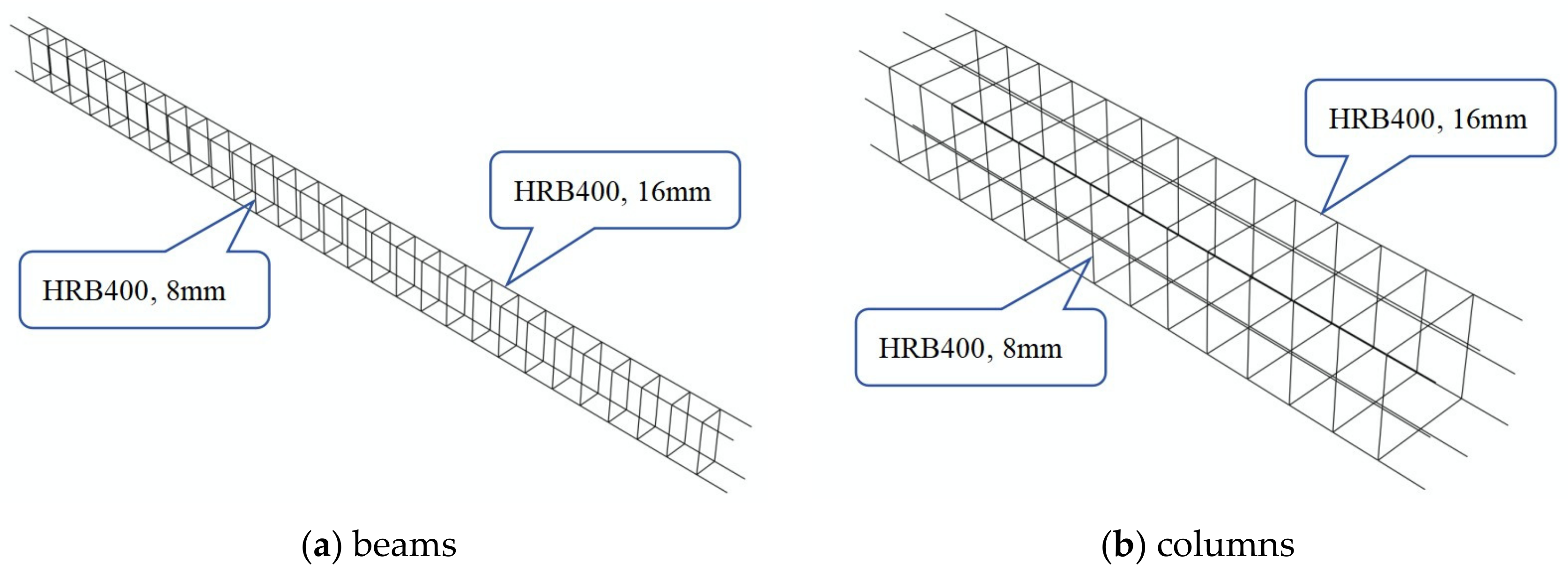
2.3. Mesh Size and Properties

The rationality of the cell grid size directly affects the calculation results and convergence. In this paper, the grid division adopts the structured grid inherent in ABAQUS, using hexahedral elements for division. The structural grid size is 0.2 m, the reinforcement grid size is 0.1 m, and the soil minimum grid size is 0.5 m. The layout method is single precision division. This layout method results in a dense grid near the structure and a sparser grid further away. The single precision division method can improve the computer calculation speed while ensuring the accuracy of the calculation results.

2.4. Boundary Condition

When analyzing the interaction between soil and structure, the range of the soil is infinite. In the numerical simulation, the soil is regarded as a semi-infinite space. That is, it needs to be calculated for the limited range of soil. For the selection of soil mass range, a too-small range will lead to a scattering wave unable to cross the artificial boundary, which will reflect and affect the accuracy of the calculation results. A too-large range will lead to too many units, which requires high computer performance and will affect the operation speed. The infinite element provided by ABAQUS is used as the artificial boundary to simulate the infinite soil mass area better. Structures can generate foundation radiational damping during seismic events, affecting the dynamic characteristics of the structure. By using an infinite element boundary, the radiational damping effect of an infinite foundation can be effectively simulated [35,36,37]. The infinite element boundary can well absorb the scattering wave. For the bottom of the soil model, we use a fixed boundary. In this simulation, the seismic wave is assumed to propagate from the bedrock surface through the soil layer and then to the structure. The structural vibration reflects the seismic wave from the soil layer to the bedrock. Due to the effect of soil damping, the amplitude will be tiny. After being reflected by the bedrock, the amplitude will be reduced again, which has little impact on the structural dynamic response.

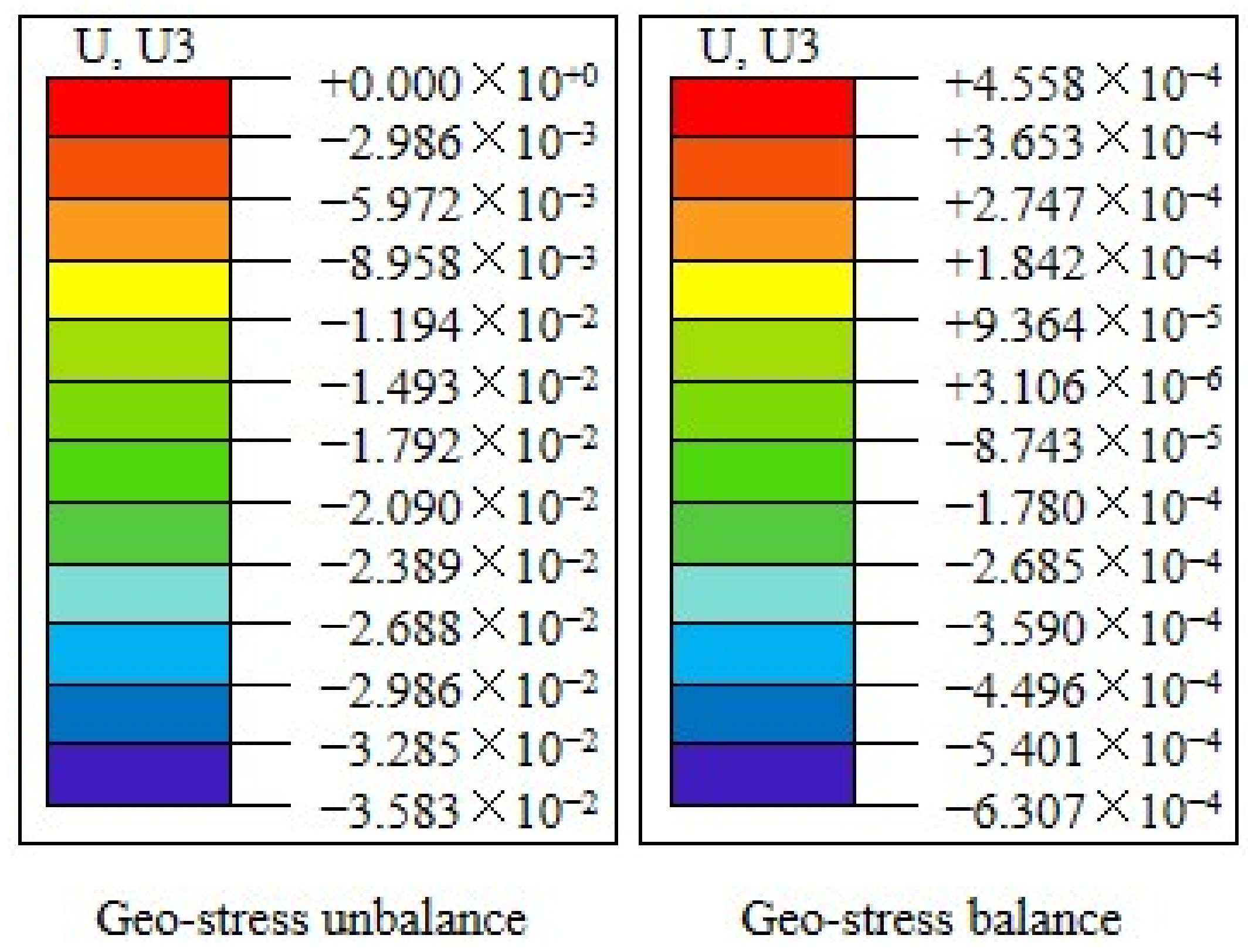
2.5. Geo-Stress Balance

Geo-stress is a kind of natural stress in the crust that is not affected by external factors. It is also called the initial stress of rock mass [38]. Balancing the geo-stress is essential in the numerical simulation of dynamic analysis. After the geo-stress is balanced, the actual situation of the site soil can be well restored, affecting the accuracy of the subsequent analysis results. ABAQUS offers several methods to balance geo-stress, including automatic balancing, extracting node stress using an inp file, and importing an ODB file for balancing. This paper uses importing an ODB file to balance the geo-stress, and good results are obtained. As shown in Figure 3, the displacement is 10−3 m when the ground stress is not balanced and 10−6 m when the ground stress is balanced. For the ground stress balance standard, when the displacement reaches 10−4 m, the result is reasonable [39], so the ground stress balance results in this paper align with the standard.
In frame structures, the characteristics of reinforced concrete components exhibit nonlinearity after experiencing seismic loads. To demonstrate the nonlinear characteristics, this paper employs suitable constitutive models and element types to represent the nonlinearity of the components. For instance, the constitutive model for concrete uses the concrete damage plasticity model available in ABAQUS. This model effectively represents the structure’s nonlinearity and accurately simulates the mechanical behavior of concrete under seismic loads. The reinforcement elements use the T3D2 element type from ABAQUS, which can simulate large deformations under seismic loads, thereby reflecting its nonlinearity. Simultaneously, the definition of plastic hinges is primarily based on the plastic zone model in ABAQUS to perform nonlinear analysis. By selecting suitable constitutive models and setting appropriate element types, the components’ yield criteria and hysteresis rules are reflected, forming plastic hinges at all possible regions of the component, which more accurately matches the actual damage scenarios of structures under seismic loads.

3. Numerical Simulation Results

3.1. Seismic Response of Four-Story Frame Structure

3.1.1. Structural Response

This paper judges frame structure damage based on its maximum inter-story displacement angle and structural damage. Based on the results, it can be concluded that temperature changes significantly affect seismic damage to the structure. When the temperature drops below 0 °C, the maximum inter-story displacement angle will decrease, which indicates that the seismic damage to the four-story frame structure will be reduced with the freezing of the soil layer. Figure 4 depicts the change rule of the maximum inter-story displacement angle.
Figure 4 illustrates the variation in the maximum inter-story displacement angle of the structure under 12 seismic waves. As a whole, the maximum inter-story displacement angle of the structure decreases with decreased ambient temperature. Figure 4a reveals that the maximum inter-story displacement angle of the structure occurs on the first and second floors when the ground motion amplitude is 0.1 g, and gradually decreases with an increase in the number of floors. This trend is attributed to the pile foundation, which connects the structure to the ground. Soil disturbances affect the foundation and transmit the resultant effects to the lower floors, producing maximum displacement angles there. At normal temperatures (i.e., 23 °C), the maximum inter-story displacement angle of the structure is generally greater than that under negative temperatures. At −5 °C, however, the change in the maximum inter-story displacement angle is between that at normal and lower temperatures, but with significant fluctuations. This behavior occurs because, below −5 °C, not all soil water freezes, resulting in an unstable ice crystal structure more susceptible to external disturbances. Consequently, different earthquakes may cause varying degrees of damage. As the temperature drops to −10 °C, the maximum inter-story displacement angle of the structure under different ground motions shows no discernible trend. This can be attributed to the fact that, at −10 °C, all of the free water in the soil freezes, resulting in a stable molecular structure of ice crystals. Additionally, the bond between ice crystals and soil particles becomes firmer, and the interaction between them is minimally affected as the temperature decreases further. This phenomenon has a significant impact on the behavior of the structure, and different ground motions can result in varying outcomes.
Figure 4b indicates that with a ground motion amplitude of 0.3 g, structural damage increases with earthquake intensity, more so than at 0.1 g. The seismic damage response law of the structure at different temperatures is similar to that of 0.1 g, but there are some inconsistencies in a few ground motions when the ground motion amplitude reaches 0.3 g. This is due to the enhanced ground motion, which increases the probability of cliff-type damage occurring in the structural mode between soil particles, water, and ice crystals in the frozen soil layer, resulting in inconsistent laws.
Damage levels in building structures are generally classified into five categories: intact, minor damage, moderate damage, severe damage, and collapse. Currently, there are no detailed boundaries defined for these five levels. By examining the overall trends in inter-story drift angles, corresponding damage levels can be preliminarily assessed. For instance, under cold winter temperatures, frame structures may experience minor to moderate damage after an earthquake. As temperatures rise, the structures are likely to undergo moderate to severe damage. In summer, when temperatures are positive, the damage to structures is the most severe, potentially resulting in severe damage or even collapse. The specific damage levels should be defined based on the actual post-earthquake damage scenarios observed. According to the research presented in this paper, by correlating the damage levels of building structures observed post-earthquake in specific seasons, it is possible to preliminarily predict the earthquake damage levels in other seasons.

3.1.2. Change Amplitude of Structural Response

From our analysis of the numerical simulation results, we propose Equation (1) to calculate the data, enhancing our understanding of how soil freezing impacts structures. This equation can be used to obtain the change amplitude of the maximum inter-story displacement angle of the structure under negative and positive temperatures.
R Δ U i h = Δ U i h ( T n ) Δ U i h ( T p ) Δ U i h ( T p )
Δ U i = U i U i 1
where R Δ U i h is the change amplitude of maximum inter-story displacement angle, Δ U i is the maximum inter-story displacement, U i is the displacement of the i t h layer, U i 1 is the displacement of the ( i 1 ) t h layer, h is the story height, T n is the negative temperature, and T p is the positive temperature.
The processed data are summarized in Table 4.
Table 4 presents the change amplitude of the maximum inter-story displacement angle. As the ambient temperature drops to a negative value when there is a frozen soil layer, the maximum inter-story displacement angle of the structure decreases significantly compared with that of the non-frozen soil layer, whether the ground motion amplitude is 0.1 g or increased to 0.3 g. To better observe the amplitude of change, the proportion histogram is drawn as shown in Figure 5. Because the seismic response of the structure will fluctuate when the temperature of the frozen soil layer is different, different negative temperatures are considered as a whole for analysis here.
Figure 5 shows the proportion of change in the maximum inter-story displacement angle. When the ground motion amplitude is 0.1 g, the reduction amplitude on the first floor of the frame structure generally ranges from 20% to 50%, while for the entire structure, it varies from 20% to 40%. With an increase in ground motion amplitude by 0.3 g, the reduction amplitude of the first floor still accounts for between 20% to 50%. Simultaneously, the overall reduction amplitude of the structure accounts for between 10% to 30%. Moreover, it can be observed from Figure 5 that when the reduction amplitude is less than 10%, the proportion of the first floor is relatively small compared to the overall structure. This is because the first layer of the structure is in direct contact with the ground, and the surface temperature changes significantly affect the first floor, leading to a higher change amplitude.
When comparing the maximum inter-story displacement angle of the structure under negative temperature conditions, the change amplitude can be calculated from the data in Table 4. Since there is a fluctuation between negative temperatures, the increase and decrease are not considered here, and only the correlation between negative temperatures is considered. When comparing different negative temperatures with −5 °C, it can be concluded that the proportion of change amplitude in the first layer of the structure is mostly less than 30%, and the overall proportion of the structure is mostly less than 20%. Compared with −10 °C, the proportion of change amplitude in the first layer is less than 20%, and the overall proportion of the structure is less than 10%.

3.1.3. Structural Damage

This paper provides a detailed analysis of the tensile and compressive damage to the four-story frame structure and assesses the damage under different temperature conditions. As there are many working conditions involved in this study, only the damage effect diagram of the structure is shown here under two ground motions, as shown in Figure 6.
Figure 6a,b show the tensile damage to the structure, and Figure 6c,d show the compression damage to the structure.
As for the evaluation criteria of tensile damage, the tensile damage factors shown in the nephogram are the same. Under the same damage factors, the damage status of the structure can be intuitively seen through the tensile damage nephogram of the structure. Figure 6a,b demonstrate significant tensile damage at the base of the first-floor columns at normal temperatures, with similar damage evident at the top of the first-floor columns and the base of the second-floor columns. For the beam part, the tensile damage area of the structure at normal temperature is more significant than that at negative temperature. In summary, the tensile damage to the structure at normal temperature is more severe than that at negative temperature. For the damage to the structure under different negative temperatures, carefully observe Figure 6a,b. From the tensile damage area of the structural column bottom and beam, it can be seen that the tensile damage to the structure will gradually decrease with the decrease in temperature. For some ground motions, the tensile damage will fluctuate when the temperature reaches −10 °C. This is because when the temperature decreases to a certain extent, the content of ice crystals in the frozen soil layer will not change significantly. At the same time, the degree of cementation between soil particles and ice crystals will also tend to be stable. This change will directly affect the superstructure so that the damage will fluctuate due to different ground motions.
When evaluating compression damage, the structural compression damage cloud diagram does not directly indicate the damage status, so the degree of damage is defined by the compression damage factor. As shown in Figure 6c,d, it can be seen from the cloud diagram that the compression damage to the structure occurs at the beam end. For the compression damage, the closer the compression damage factor is to 1, the more serious the damage is. By observing the magnitude of the compression damage factor, it can be concluded that for the El-Centro seismic wave, the maximum compression damage factor of the structure at normal temperature is 0.363, 0.3508 at −5 °C, 0.3346 at −10 °C, 0.3263 at −15 °C, and 0.3209 at −20 °C. For the Kobe seismic wave, the maximum compression damage factor of the structure at normal temperature is 0.3732, 0.3692 at −5 °C, 0.3293 at −10 °C, 0.3556 at −15 °C, and 0.3256 at −20 °C. It can be concluded that the compression damage factor of the structure at normal temperature is significantly greater than that at negative temperature. That is, the compression damage to the structure at normal temperature is more serious. Concerning the compression damage to the structure at various negative temperatures, the data indicate that at −10 °C, the structure’s compression damage is significantly less than that at −5 °C and normal temperatures. When the temperature continues to drop, the amplitude of the change in the compression damage factor will decrease. The structural compression damage fluctuates after the temperature reaches −10 °C under some ground motions, and the principle is similar to the tensile damage.
Analysis of the damage reveals that structural damage, from both compression and tension, is more severe at normal temperatures than at negative temperatures. This indicates that seismic damage to the four-story frame structure under negative temperatures is significantly less than that under normal temperatures. The extent of seismic damage varies at different negative temperatures, with −5 °C resulting in either similar or significantly different damage compared to normal temperatures. The reason for this is that the water in the soil does not completely freeze, resulting in an unstable ice crystal structure that is more susceptible to external factors. Therefore, there are two distinct scenarios. At −10 °C, all water molecules in the soil freeze into ice crystals, leading to significant differences between the seismic damage at normal temperature and that at −10 °C. As the temperature drops further, the impact of temperature on the seismic damage to the structure becomes less significant.

3.2. Seismic Response of Sixteen-Story Frame Structure

3.2.1. Structural Response

Numerical simulation was used to obtain the changes in the maximum inter-story displacement angle in response to seismic damage for a sixteen-story frame structure. The obtained data indicate that the environmental temperature has a significant impact on the structural damage resulting from seismic activity. To better visualize the changing trend of the maximum inter-story displacement angle, the data obtained from numerical simulation are plotted in Figure 7.
Figure 7a shows that the ground motion amplitude is 0.1 g. The maximum inter-story displacement angle of the structure is smaller when the ambient temperature is negative compared to normal temperature. At −5 °C, the maximum inter-story displacement angle is significantly reduced compared to the normal temperature. At −10 °C, there will still be some differences in the change in the maximum inter-story displacement angle of the structure, but the amplitude is smaller than that at −5 °C and normal temperature. As the temperature continues to decrease and reaches −15 °C and −20 °C, the change in maximum inter-story displacement angle of the structure becomes very small. From Figure 7a, it is also clear that for the sixteen-story frame structure, the change in the maximum inter-story displacement angle between different negative temperatures is more regular than for the four-story frame structure, with less fluctuation. This consistency is due to the significant dead weight of the sixteen-story frame structure, which increases downward pressure and friction between the piles and the soil, thereby enhancing stability. At −5 °C, the mechanical parameters of the soil will undergo significant changes compared to positive temperatures, leading to a significant difference in the maximum inter-story displacement angle. As the temperature decreases, various mechanical parameters of the soil continue to change, but the lower the temperature, the smaller the trend. At this time, with increasing self-weight of the upper structure, the environmental temperature will have a smaller impact on it, resulting in a smaller difference in the maximum inter-story displacement angle of the sixteen-story structure under different negative temperature conditions.
When the ground motion amplitude is 0.3 g, it can be seen from Figure 7b that the variation law of the maximum inter-story displacement angle under different ground motions will have certain differences. Furthermore, structural damage under certain ground motions fluctuates significantly with temperature changes. This fluctuation is due to enhanced ground motion, which likely causes cliff-type damage within the interactions of soil particles, water, and ice crystals in the frozen soil. At the same time, the longitudinal dimension of the structure is high. The fluctuation will produce a flexible swing phenomenon with the increase in floors. The higher the floors are, the less impact the frozen soil layer will have, leading to large fluctuations. However, the rule is evident for the bottom layer of the structure. The maximum inter-story displacement angle of the structure’s bottom layer is significantly smaller at negative temperatures than at normal temperatures. This is because the bottom layer directly contacts the ground through the piles, which are greatly affected by the soil layer.

3.2.2. Change Amplitude of Structural Response

From Figure 7, it can be seen that for high-rise structures, although the maximum inter-story displacement angle of the structure will exhibit varying degrees of flexible oscillation with the increase in floors under different environmental temperatures, it can be seen that the maximum inter-story displacement angle of the structure is significantly greater at positive temperatures than at negative temperatures. To compare the seismic damage to high-rise structures in different seasons, Equation (1) can also be used to calculate the amplitude of maximum inter-story displacement angle changes under positive and negative temperatures. Due to the large amount of data and occupying a considerable amount of space, the average values of the calculated data were taken. The results are shown in Table 5.
Upon analyzing Table 5, it can be concluded that when the ground motion amplitude is 0.1 g and the temperature drops to negative values, the maximum inter-story displacement angle change of the overall structure will be greatly reduced. For the overall structure, the inter-story displacement angle decreases by up to 50% at negative temperatures compared to positive temperatures. For the first floor of the structure, the maximum reduction can reach 40%. When the ground motion amplitude is 0.3 g, the overall reduction of the structure can reach a maximum of 30%, with the first floor experiencing a maximum reduction of 20%. It is evident that high-rise structures are highly sensitive to environmental temperature changes; thus, seasonal variations must be fully considered in structural design.
Based on the simulation results of this paper, it is concluded that changes in environmental temperature caused by seasonal changes will significantly affect the damage to structures after earthquakes. Whether it is a multi-layer structure or a high-rise structure, this impact cannot be ignored. Figure 5 in this paper shows that the reduction in damage to structures after earthquakes under negative temperatures is mostly between 20% and 50% compared to that under positive temperatures. In light of this, we propose incorporating this conclusion into the design of the structure, based on the original seismic code. When building structures under negative temperatures, it is possible to accurately predict the damage to the structure following an earthquake at positive temperatures, thereby enhancing the design details of the structure based on the original design and guaranteeing its safety. When building structures under positive temperatures, it is possible to adjust the structural design to ensure the economic efficiency of the building structure.

4. Conclusions

In this paper, using the numerical simulation software ABAQUS, a detailed analysis of frozen soil–structure interaction is conducted for a four-story frame structure and a sixteen-story frame structure, respectively, and the earthquake damage under different ambient temperatures and different earthquake intensities is obtained. The following conclusions were drawn:
(1)
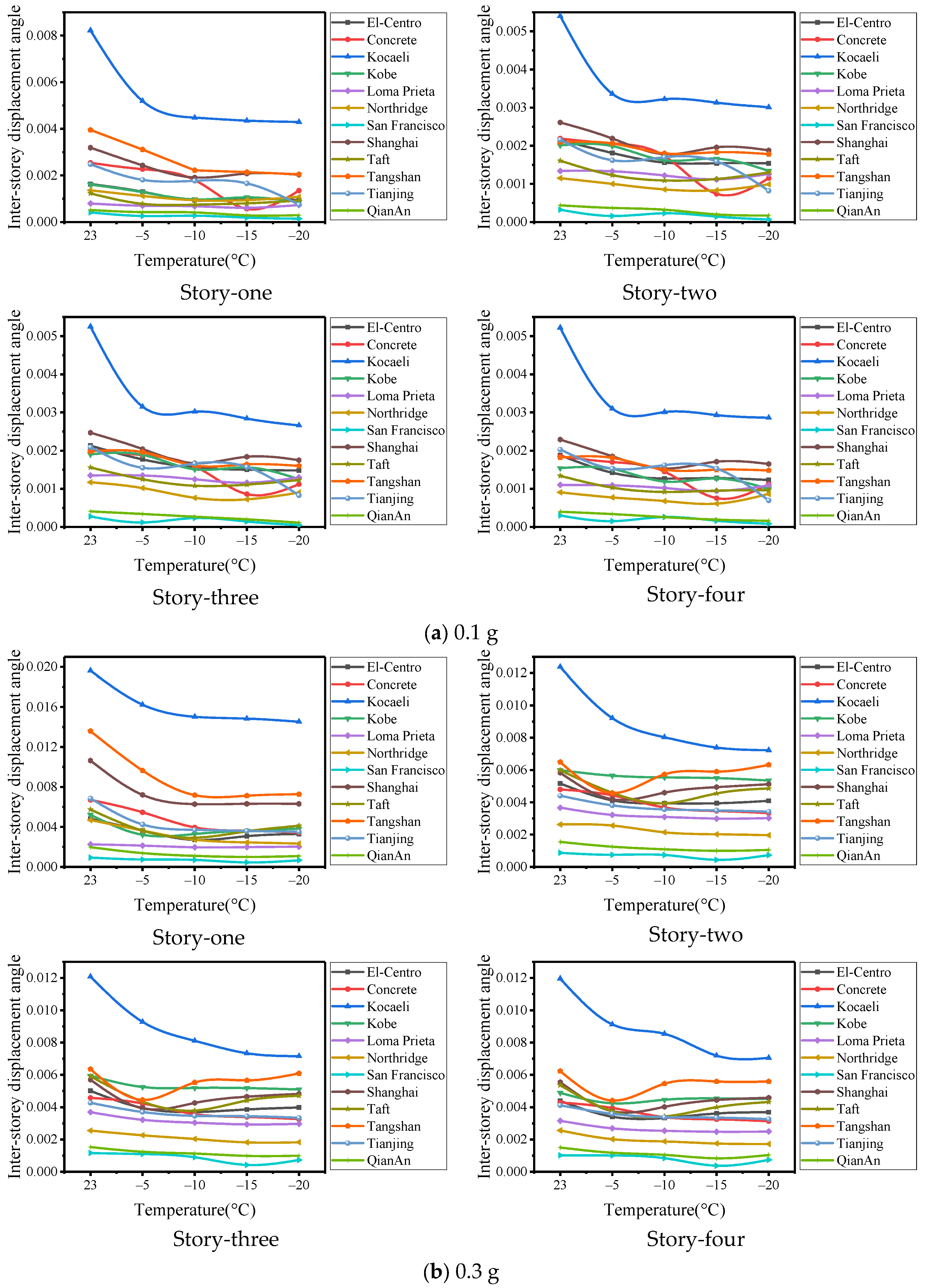
For the frame structure under the ground motion of 0.1 g and 0.3 g, the structure’s maximum inter-story displacement angle in the presence of frozen soil layer is significantly reduced compared to the case without frozen soil layer.
(2)
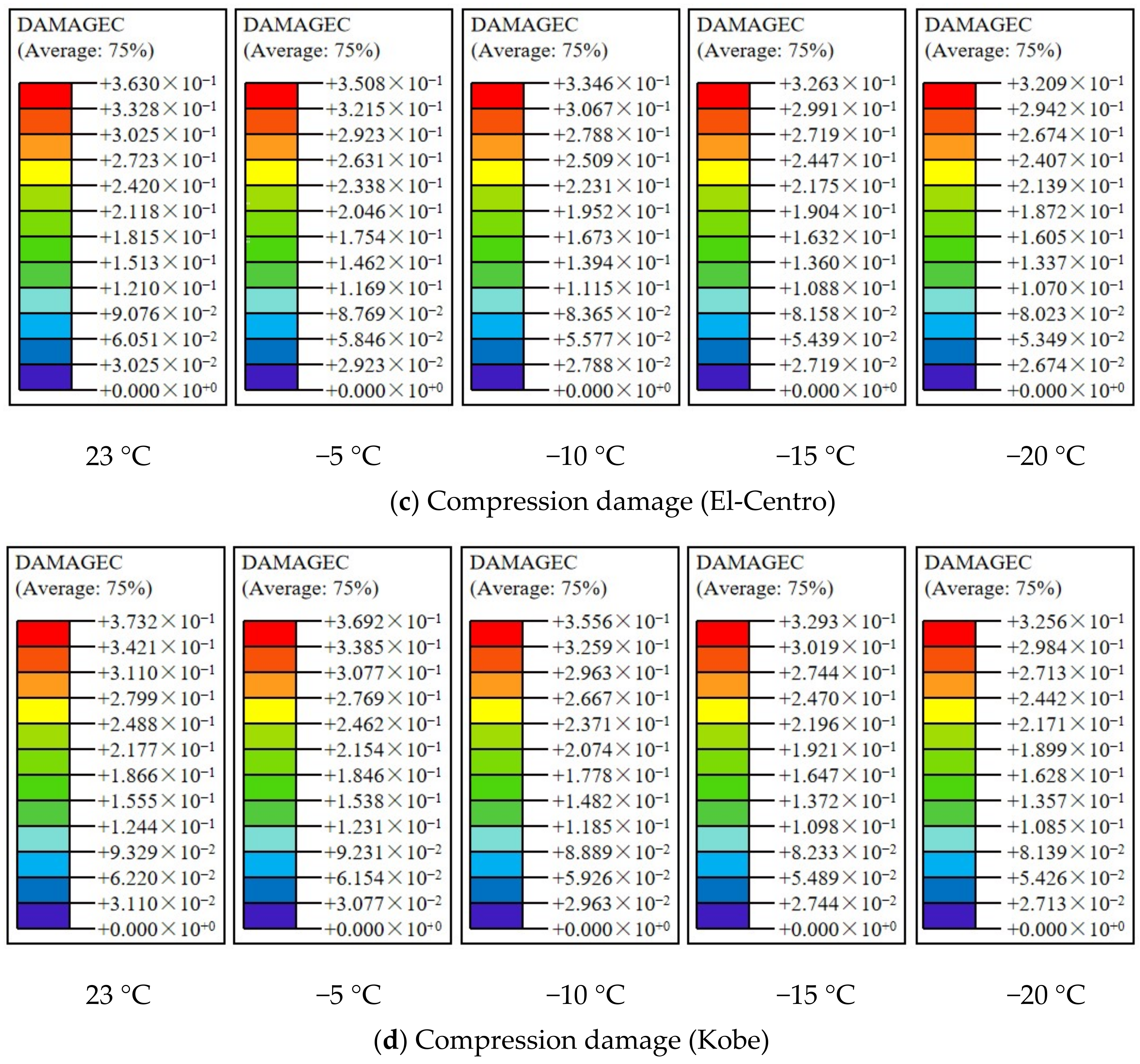
When the ambient temperature is −5 °C, the seismic damage to the structure fluctuates wildly and will be close to that at the normal temperature and the lower negative temperature. When the ambient temperature is −10 °C, −15 °C, or −20 °C, the damage levels fluctuate relative to each other.
(3)
For the first floor of a four-story frame structure, when the temperature drops below 0 °C, the maximum inter-story displacement angle reduction amplitude is mostly between 20 and 50%. For the overall structure, the reduction amplitude is mainly between 20 and 40%. When the ground motion amplitude is increased to 0.3 g, the reduction amplitude of the first floor is also between 20 and 50%, and that for the overall structure is between 10 and 30%.
(4)
For the sixteen-story frame structure, when the temperature drops below 0 °C, the first floor’s maximum inter-story displacement angle reduction amplitude can reach 40%. For the overall structure, the reduction amplitude can reach 50%.
(5)
When the ambient temperature is negative, the tensile damage and compression damage to the frame structure are relatively minor. When the ambient temperature is positive, the damage will be more serious. The tensile damage to the structure mainly occurs at the column end (more severe at the bottom) and the whole beam, while the compressive damage to the structure mainly occurs at the beam end.
(6)
By analyzing the evolutionary patterns of damage status of the structure in the sequence of seasonal changes in spring, summer, autumn, and winter, it is observed that the damage status demonstrates an increasing trend followed by a decreasing trend.

Author Contributions

X.B.: Conceptualization, Methodology, Validation, Software, Writing—original draft. G.W.: Methodology, Writing—review and editing, Supervision, Funding acquisition. All authors have read and agreed to the published version of the manuscript.

Funding

This work was supported by the National Key Research and Development Program of China [2018YFD1100405].

Data Availability Statement

Data generated or analyzed during this study are available from the corresponding author upon reasonable request.

Conflicts of Interest

The authors declare there are no conflicts of interest.

References

  1. Guo, D.M. Preliminary analysis of the impact field and seismic geological conditions of the 1986 Dedu earthquake. Northeast. Seismol. Res. 1987, 3, 57–68. [Google Scholar]
  2. Zhang, F.M.; Yi, F.L. Source parameters of Dedu moderate earthquake of Heilongjiang province in 1986. Seismol. Res. Northeast China 1995, 11, 34–38. [Google Scholar]
  3. Liu, H.X.; Sun, Y.F.; Chen, Y.M.; Xu, X.Y.; Yin, Y.H. Influence of seasonally frozen ground on the seismic damages of buildings. J. Glaciol. Geocryol. 1998, 20, 46–50. [Google Scholar]
  4. Wu, L.B.; Qi, W.; Niu, F.J.; Niu, Y.H. A review of studies on roadbed frozen damage and countermeasures in seasonal frozen ground regions in China. J. Glaciol. Geocryol. 2015, 37, 1283–1293. [Google Scholar]
  5. Osama, A.; Sameer, A.D. Comparison of solar thermal and solar electric space heating and cooling systems for buildings in different climatic regions. Sol. Energy 2019, 11, 545–560. [Google Scholar]
  6. Li, N.; Chen, B.; Chen, F.; Xu, X. The coupled heat-moisture-mechanic model of the frozen soil. Cold Reg. Sci. Technol. 2000, 31, 199–205. [Google Scholar] [CrossRef]
  7. Evans, S.G.; Ge, S.; Voss, C.I.; Molotch, N.P. The role of frozen soil in groundwater discharge predictions for warming alpine watersheds. Water Resour. Res. 2018, 54, 1599–1615. [Google Scholar] [CrossRef]
  8. Zhang, Z.Q.; Wu, Q.B.; Xun, X.Y.; Wang, B.X.; Xu, N. Climate change and the distribution of frozen soil in 1980–2010 in northern northeast China. Quat. Int. 2018, 467, 203–241. [Google Scholar] [CrossRef]
  9. Chen, S.S.; Zang, S.Y.; Sun, L. Permafrost degradation in northeast China and its environmental effects: Present situation and prospect. J. Glaciol. Geocryol. 2018, 40, 298–306. [Google Scholar]
  10. Tan, L.; Wei, C.F.; Tian, H.H.; Zhou, J.Z.; Wei, H.Z. Experimental study of unfrozen water content of frozen soils by low-field nuclear magnetic resonance. Rock Soil Mech. 2015, 36, 1566–1572. [Google Scholar]
  11. Ladanyi, B. An engineering theory of creep of frozen soils. Can. Geotech. J. 1972, 9, 63–80. [Google Scholar] [CrossRef]
  12. Chamberlain, E.; Groves, C.; Perham, R. The mechanical behaviour of frozen earth materials under high pressure triaxial test conditions. Geotechnique 1972, 23, 136–147. [Google Scholar] [CrossRef]
  13. Zhu, Y.; Carbee, D.L. Uniaxial compressive strength of frozen silt under constant deformation rates. Cold Reg. Sci. Technol. 1984, 9, 3–15. [Google Scholar] [CrossRef]
  14. Wu, Z.J.; Ma, W.; Wang, L.M.; Cheng, J.J.; Feng, W.J. Laboratory study on the effect of temperature and confining pressure on strength of frozen soil under seismic dynamic loading. J. Glaciol. Geocryol. 2003, 25, 648–652. [Google Scholar]
  15. Li, X.L.; Wang, H.J.; Zou, S.J.; Ma, H.C.; Niu, Y.H. Research state of deformation characteristics of frozen soil under cyclic loading and problems in frozen soil excavation. J. Glaciol. Geocryol. 2017, 39, 92–101. [Google Scholar]
  16. Wang, R.M.; Ma, Q.Y. Experimental analysis of the influence of freezing time on compressive strength of frozen silty clay. J. Anhui Univ. Sci. Technol. (Nat. Sci.) 2019, 39, 74–79. [Google Scholar]
  17. Toki, K.; Miura, F. Non-linear seismic response analysis of soil-structure interaction systems. Earthq. Eng. Struct. Dyn. 1983, 11, 77–89. [Google Scholar] [CrossRef]
  18. Makris, N.; Badoni, D.; Delis, E.; Gazetas, G. Prediction of observed bridge response with soil-pile-structure interaction. J. Struct. Eng. 1994, 120, 2992–3011. [Google Scholar] [CrossRef]
  19. Wijaya, P.K. Boundary element model coupled with finite element model for dynamic soil-pile interaction. In Proceedings of the 2009 Third Asia International Conference on Modelling and Simulation, Bundang, Indonesia, 25–29 May 2009; pp. 491–496. [Google Scholar]
  20. Ilaria, V.; Diana, S.; Claudio, T. The effect of soil-foundation-structure interaction on the wind-induced response of tall buildings. Eng. Struct. 2014, 7, 117–130. [Google Scholar]
  21. Renzi, S.; Madiai, C.; Vannucchi, G. A simplified empirical method for assessing seismic soil-structure interaction effects on ordinary shear-type buildings. Soil Dyn. Earthq. Eng. 2013, 55, 100–107. [Google Scholar] [CrossRef]
  22. Zhang, Y.X.; Wang, X.X.; Zhuang, H.Y. Fine numerical modeling of nonlinear soil-pile-frame structure interaction system and its verification. J. Disaster Prev. Mitig. Eng. 2010, 30, 558–566. [Google Scholar]
  23. Xu, J. Seismic Response Analysis of Transmission Tower-Line System Considering SSI; Dalian University of Technology: Dalian, China, 2008. [Google Scholar]
  24. Jendoubi, A.; Legeron, F. Effect of the dynamic soil-structure interaction on rigid transmission line towers subjected to wind and impulse loads. Electr. Transm. Substation Struct. 2012, 27, 250–261. [Google Scholar]
  25. Ma, M.J. The Seismic Performance Simulation Analysis of the Irregular of Castle Hotel of Dalian Considering the SSI Effect; Liaoning Technical University: Fuxin, China, 2013. [Google Scholar]
  26. Mi, P. Adverse Impact on Seismic Performance Analysis of Frame Structure Considering Soil-Structure Interaction; Guangzhou University: Guangzhou, China, 2016. [Google Scholar]
  27. ForcelIini, D. Seismic assessment of a benchmark based isolated ordinary building with soil structure interaction. Bull. Earthq. Eng. 2017, 12, 2021–2042. [Google Scholar] [CrossRef]
  28. Forcellini, D. Cost assessment of isolation technique applied to a benchmark bridge with soil structure interaction. Bull. Earthq. Eng. 2016, 15, 51–69. [Google Scholar] [CrossRef]
  29. Zhao, C.; Valliappan, S. A dynamic infinite element for three-dimensional infinite-domain wave problems. Int. J. Numer. Methods Eng. 1993, 36, 2567–2580. [Google Scholar] [CrossRef]
  30. Jiang, X.L.; Xu, Y.; Zheng, G. Finite element and infinite element coupling method for seismic analysis of soil-underground tunnel system. Earthq. Eng. Eng. Vib. 1999, 19, 22–26. [Google Scholar]
  31. Nielsen, A.H. Towards a complete framework for seismic analysis in ABAQUS. Eng. Comput. Mech. 2014, 167, 3–12. [Google Scholar] [CrossRef]
  32. Deeks, A.J.; Randolph, M.F. Axisymmetric time-domain transmitting boundaries. J. Eng. Mech. 1994, 120, 25–42. [Google Scholar] [CrossRef]
  33. Liu, J.B.; Wang, Z.Y.; Du, X.L.; Du, Y.X. Three-dimensional visco-elastic artificial boundaries in time domain for wave motion problems. Eng. Mech. 2005, 22, 46–51. [Google Scholar]
  34. Bian, X.Y.; Wang, G.X.; Li, Y.D. Experimental research on dynamic characteristics of frozen clay considering seasonal variation. Geomech. Eng. 2024, 36, 391–406. [Google Scholar]
  35. Li, Z.Q.; Du, C.B.; Ai, Y.M. Effect of radiation damping on seismic response of structures. J. Hohai Univ. (Nat. Sci.) 2009, 37, 400–404. [Google Scholar]
  36. Huang, S.; Chen, W.Z.; Wu, G.J.; Guo, X.H.; Qiao, C.J. Study of method of earthquake input in aseismic analysis for underground engineering. Chin. J. Rock Mech. Eng. 2010, 29, 1254–1262. [Google Scholar]
  37. Song, J.K.; Liu, Z.X.; Zhou, X.J. Analysis of the nonlinear earthquake responses of the Hong Kong-Zhuhai-Macao immersed tunnel. Chin. J. Undergr. Space Eng. 2015, 11, 323–331. [Google Scholar]
  38. Cai, M.F.; Qiao, L. Geostress Measurement Principle and Technology; Science Press: Beijing, China, 1995. [Google Scholar]
  39. Dai, R.L.; Li, Z.F.; Wang, J. Research on initial geo-stress balance method based on ABAQUS. J. Chongqing Technol. Bus. Univ. (Nat. Sci. Ed.) 2012, 9, 76–81. [Google Scholar]
Figure 1. Reinforcement details.
Buildings 14 01493 g001
Figure 2. Frame structure.
Buildings 14 01493 g002
Figure 3. Geo-stress balance.
Buildings 14 01493 g003
Figure 4. Maximum inter-story displacement angle of four-story frame structure.
Buildings 14 01493 g004
Figure 5. Proportion of change in maximum inter-story displacement angle (four-story).
Buildings 14 01493 g005
Figure 6. Tensile damage and compression damage to the four-story frame structure.
Buildings 14 01493 g006aBuildings 14 01493 g006b
Figure 7. Maximum inter-story displacement angle of sixteen-story frame structure.
Buildings 14 01493 g007aBuildings 14 01493 g007b
Table 1. Temperature change in Harbin.
MonthDaily Average Maximum
Temperature (°C)
Daily Average Minimum
Temperature (°C)
Historical
Maximum
Temperature (°C)
Historical
Minimum
Temperature (°C)
January−14−25−1−34
February−8−206−30
March3−922−24
April15232−7
May2211341
June2817389
July29203514
August2719358
September221129−2
October12125−12
November0−916−24
December−11−217−32
Table 2. Distribution of soil layers in the geological survey report.
Soil TypeSoil Thickness (m)Soil Properties
Miscellaneous fill0.60–1.00Mixed colors, mainly composed of construction waste, including sticky soil, with black sedimentary soil at the bottom.
Silty clay 17.80–8.90Yellow-brown, plastic to rigid, with high dry strength and high toughness.
Silty clay 22.00–4.70Brown, plastic, with moderate dry strength and moderate toughness.
Silty clay 31.10–3.60Gray-yellow to gray, soft plastic to plastic, with moderate dry strength and low toughness.
Fine sand 11.00–1.00Yellow, slightly dense to moderately dense, slightly moist.
Fine sand 24.70–4.90Gray, slightly dense.
Medium sand1.70–2.00Gray, moderately dense.
Coarse sand4.50–5.50Yellow, moderately dense.
Table 3. Soil parameters.
Soil Thickness (m) and Soil TypeTemperature (°C)Density (kg/m³)Elastic Modulus (MPa)Cohesion (kPa)Internal Friction Angle (°)
2.5 (Clay)23148097.138.99.6
−51480244.7173.527.4
−101480462.1343.734.1
−151480540.1367.533.2
−201480568.9382.432.9
6.5 (Silty clay 1)231930204.336.115.9
3.5 (Silty clay 2)231890173.326.811.1
1.5 (Silty clay 3)231860140.226.610.0
1 (Fine sand 1)231840312.16.028.0
3 (Silty clay 3)231860140.226.610.0
5 (Fine sand 2)231840272.96.025.0
2 (Medium sand)231840302.53.030.0
5 (Coarse sand)231840358.92.035.0
Table 4. The change amplitude of maximum inter-story displacement angle (four-story structure).
Seismic WaveFloor0.1 g0.3 g
−5 °C−10 °C−15 °C−20 °C−5 °C−10 °C−15 °C−20 °C
El-Centro10.20.430.390.430.250.440.360.32
20.160.270.280.280.20.240.240.21
30.170.270.30.310.210.260.230.21
40.240.320.320.350.220.240.180.16
Average value19.25%32.25%32.25%34.25%22.00%29.50%25.25%22.50%
Kocaeli10.370.450.470.480.170.230.240.26
20.380.400.420.440.260.350.400.42
30.400.420.460.490.230.330.390.41
40.410.420.440.450.240.290.400.41
Average value38.81%42.67%44.72%46.65%22.45%30.01%35.95%37.34%
Loma Prieta10.120.150.230.080.050.130.120.1
20.010.090.160.060.120.160.190.18
300.070.140.040.130.180.210.2
40.010.070.140.010.150.20.220.21
Average value3.50%9.50%16.75%4.75%10.25%18.25%18.50%17.25%
Northridge10.180.310.310.210.230.420.480.5
20.130.260.280.140.030.190.230.25
30.130.350.380.230.110.20.290.28
40.150.250.330.050.210.270.320.33
Average value14.75%29.25%32.50%15.75%14.50%27.00%33.00%34.00%
Concrete10.110.290.780.470.190.410.460.49
20.060.210.660.470.080.230.280.31
30.070.220.580.450.080.220.260.29
40.080.220.590.390.080.210.240.27
Average value8.00%23.50%65.25%44.50%10.75%26.75%31.00%34.00%
Kobe10.20.40.340.470.380.370.310.27
20.010.190.170.330.060.080.080.11
30.010.210.180.340.120.130.130.14
40.010.230.180.360.130.090.070.08
Average value5.75%25.75%21.75%37.50%17.28%16.48%14.70%14.86%
Shanghai10.240.40.350.360.320.410.410.41
20.160.320.250.280.280.210.150.12
30.170.320.260.290.310.250.180.15
40.190.330.250.280.320.280.20.17
Average value19.00%34.25%27.75%30.25%30.75%28.75%23.50%21.25%
San Francisco10.370.340.530.650.20.250.520.29
20.510.290.560.80.140.160.50.16
30.570.160.480.820.050.220.640.37
40.490.130.460.720.010.170.630.27
Average value48.50%23.00%50.75%74.75%10.00%20.00%57.25%27.25%
QianAn10.180.20.440.430.30.440.490.45
20.150.260.540.620.190.30.360.32
30.160.340.510.730.190.260.360.35
40.150.350.520.60.210.30.440.31
Average value16.00%28.75%50.25%59.50%22.25%32.50%41.25%35.75%
Tangshan10.210.440.460.480.290.470.480.47
20.010.140.120.150.290.120.090.03
30.010.190.170.190.30.130.110.04
40.010.180.180.190.290.130.10.1
Average value6.00%23.75%23.25%25.25%29.25%21.25%19.50%16.00%
Tianjing10.270.290.330.70.380.460.480.49
20.250.210.260.620.140.190.210.22
30.260.210.250.60.130.190.190.22
40.250.20.250.660.130.180.190.21
Average value25.75%22.75%27.25%64.50%19.50%25.50%26.75%28.50%
Taft10.370.390.350.250.370.490.380.28
20.240.320.30.190.230.340.240.19
30.20.310.290.210.270.360.250.2
40.230.310.290.280.30.360.250.19
Average value26.00%33.25%30.75%23.25%29.25%38.75%28.00%21.50%
Table 5. The change amplitude of maximum inter-story displacement angle (sixteen-story structure).
Seismic WavePosition0.1 g0.3 g
−5 °C−10 °C−15 °C−20 °C−5 °C−10 °C−15 °C−20 °C
El-CentroFirst floor13.13%16.45%18.44%16.45%21.96%15.25%11.15%10.37%
Entire structure20.00%28.00%27.56%26.81%22.00%15.88%16.69%17.63%
Loma
Prieta
First floor19.09%21.52%26.97%23.03%29.34%23.66%24.29%25.87%
Entire structure14.75%21.94%22.50%21.38%24.38%29.31%29.25%31.31%
TaftFirst floor36.49%40.54%38.29%41.44%2.40%8.32%4.81%5.36%
Entire structure49.88%53.75%51.94%55.19%16.63%25.06%24.19%24.50%
Disclaimer/Publisher’s Note: The statements, opinions and data contained in all publications are solely those of the individual author(s) and contributor(s) and not of MDPI and/or the editor(s). MDPI and/or the editor(s) disclaim responsibility for any injury to people or property resulting from any ideas, methods, instructions or products referred to in the content.

