Article

Study on the Diffusion Parameters of Newtonian Fluid in High-Pressure Jet Disturbance Grouting

College of Water Conservancy and Civil Engineering, Shandong Agricultural University, Taian 271000, China
*
Authors to whom correspondence should be addressed.
Buildings 2024, 14(6), 1491; https://doi.org/10.3390/buildings14061491
Submission received: 31 March 2024 / Revised: 15 May 2024 / Accepted: 16 May 2024 / Published: 21 May 2024
(This article belongs to the Section Building Energy, Physics, Environment, and Systems)

Abstract

:
In order to investigate the diffusion mechanism of slurry in post-pile grouting, this study develops a formula for calculating the diameter and the climb height of the cement core of jet grouting (CCJG). This research conducts field orthogonal tests using a self-developed grouting nozzle to analyze the effects of disturbance pressure (DP), disturbance time (DT), grouting pressure (GP), and the water–cement ratio (W/C) on the dimensions and strength of the CCJG. The findings revealed that the theoretical formula for calculating the diameter of the CCJG deviates by approximately 8% from the field test results, confirming the formula’s validity. In addition, the DP and DT significantly influence the volume of the CCJG, displaying a linear increase with their augmentation. Conversely, the W/C and DP predominantly affect the CCJG’s strength. Notably, an increase in the W/C results in diminished strength, whereas an increase in the DP enhances it. In addition, soil reinforcement is achieved through replacement, mixing, and compaction as the grout flows outward from the center of the grouting hole. These insights offer a theoretical foundation and technical support for effective grouting construction practices.

1. Introduction

Grouting technology has been extensively applied in diverse engineering fields such as architecture, highways, subways, mines, tunnels, hydropower, the military, railways, metallurgy, and foundation treatment [1]. The technology of post-pile grouting effectively improves the bearing capacity of piles and reduces settlement. In this paper, soil and cement mixed with each other form part of the mixture, which is called the CCJG. The process of grouting involves mixing material into a flowing slurry and then injecting this slurry into the soil or rock cracks using pressure equipment, which enhances the physical and mechanical properties of the soil and rock [2]. With reinforcement by grouting, the resistance to the pile top load significantly increases [3], and the ultimate bearing capacity can rise by over 40% [4]. The study [5] indicated that the soil strength below the pile base substantially improved following grouting. And research on the reinforcement effect of high-pressure jet grouting has attracted the attention of scholars. The impact of jet grouting technology on tunnel settlement has been investigated [6,7], and studies have shown that it is effective in reducing sedimentation. In Tao’s research, the impact of the shaft tip resistance on the lateral resistance of large-diameter drilled shafts before and after combined grouting was investigated through full-scale field testing. In view of this, grouting theory and the grouting parameters are studied in this paper.
However, ensuring the quality of reinforcement presents considerable challenges [8]. Existing studies have found that different types of soil and slurry have a great influence on the post-grouting effect, so the quality of grouting stabilization is difficult to guarantee. The soil type has the greatest influence on the grouting effect. For instance, in Zhao’s study [9], the effect of the grout energy, soil resistance, and soil type on the stabilization diameter during jet grouting was examined. In Zhang’s study, jet grouting was used to reinforce water-rich sand layers [10], and it was concluded that the permeability and diffusion laws of different bottom layers and slurries were different. Controlling the range and shape of grouting and the effect of grouting stabilization is difficult in practical engineering due to the uneven distribution of weak soil planes and variability in permeability of cement [11].
In order to control the grouting effect and understand the law of slurry diffusion, researchers have conducted many studies in this area. Yang et al. involved theoretical analysis and experimental methods to investigate the rheological equations of power-law fluids, Bingham fluids, and Newtonian fluids [12,13,14], leading to the derivation of theoretical formulas for grouting diffusion under these three flow states. Similarly, many studies [15,16] have proposed formulas for calculating the grouting diffusion radius of Bingham fluids based on rheological and constitutive equations and examined the influencing factors for this radius. A 2D cylindrical permeation grouting diffusion model has been developed [10], considering the non-uniform distribution of the grout’s viscosity and validating the consistency between the experimental results and the theoretical model. Ding [17] established a rheological equation and a seepage motion equation for Newtonian fluid, considering the time-dependent behavior of the rheological parameters. A calculation model for slurry’s diffusion radius along a hemispherical surface under altered slurry viscosity conditions [18] has been proposed. Computational fluid dynamics (CFD) software has also been used to explore the pressure and velocity distribution in the jet flow field of clean water and cement slurry with varying W/C ratios [19].
Although many scholars have concentrated on studying slurry’s diffusion behavior in various constitutive models, taking into account the jet grouting stabilization mechanisms and reinforcement efficiency, research on slurry flow control under high-pressure self-rotating jet conditions is limited, as is evaluation of the grouting effects, which often considers only single-factor influences, with relatively restricted evaluation methods. Hence, this study proposed a theoretical formula for the diffusion parameters of Newtonian fluid and developed a new type of grouting nozzle for high-pressure rotary jetting, and the influence of different grouting parameters on the stabilization effect was studied. When grouting is conducted in the soil, the slurry can influence the soil on the pile side and the tip soil. This part of the mixture of soil and cement slurry is called the CCJG, which can improve the ultimate bearing capacity of the pile. A uniaxial compressive strength test was carried out on the coring of the CCGJ to study its compressive performance. This new nozzle can improve the post-grouting effect by adjusting the duration of disturbance (DT), disturbing pressure (DP) grouting pressure (GP), and water–cement ratio (W/C) and adapt to different soil environments to ensure adequate grouting results. Subsequent field tests analyzed the impact of the DP, DT, GP, and W/C on the size and strength of the CCJG. The findings from these on-site simulation tests provide a theoretical foundation and technical support for practical grouting construction.

2. Diffusion Law

2.1. Diameter Formula for the CCJG

The slurry, assumed to be a Newtonian fluid to compute its climbing height, is subject to several assumptions [20]: (1) The soil is considered homogeneous and uniform; (2) The slurry flow pattern remains constant during the grouting process, exhibiting incompressible, homogeneous, and isotropic characteristics; (3) The nature of the slurry’s viscosity is considered time-dependent; (4) The roughness of the pile side wall is disregarded, and the pile body is assumed to be a regular cylinder. Based on the findings from the literature [21], the soil properties and grouting nozzles predominantly influence the diameter of the CCJG. Hence, this study introduces a formula to calculate the CCJG’s diameter under high-pressure self-rotary jet grouting based on the assumptions in the literature [22]. Compared with the traditional method for calculating the diameter of the jet grouting pile, the diameter calculation formula for our self-rotating grouting nozzle is as follows.
D p = 2 η a x L
x L = d v v L
η a = R X L = [ a 1 ( P n + a 2 a 3 ) a 4 + ( a 3 P n + a 2 ) a 4 a 5 ] 1 3
v o = μ 2 g P n / γ
v L = β q u P atm
q u = 2 σ tan ( φ )  
a 1 = 1 I r 1 + ( 1 1 + v o 2 E 4 sin φ 3 sin φ ( q + c cot φ ) ) 3
a 2 = c · cot φ
a 3 = 3 ( 1 + sin φ ) 3 sin φ ( q + c cot φ )
a 4 = 3 ( 1 + sin φ ) 4 sin φ
a 5 = 1 I r
q = k 0 γ L
k 0 = 1 sin ϕ

2.2. Modeling the Climb Height of Slurry

The rheological equation for Newtonian fluid (Sandra et al., 2012 [8] and Yang et al., 2016 [14]) is as follows:
τ = η λ
A model representing the slurry climb height under high pressure is depicted in Figure 1. A microelement of the slurry, with an arbitrary length dL and thickness r, is considered for the force analysis. The mechanical balance conditions in the microelement, in the vertical direction when the cement grout flow is steady, are detailed in Equation (15):
π [ ( r 1 + r 0 2 + r ) 2 ( r 1 + r 0 2 r ) 2 ] [ ( p + d p ) + γ g d L P ] + 2 π τ [ ( r 1 + r 0 2 + r ) + ( r 1 + r 0 2 r ) ] d L = 0
The simplified result of the above equation is shown in Equation (16).
τ = - ( d p d L + γ g ) r
Substituting Equation (16) into Equation (14), we can derive Equation (17).
γ = d v d r = 1 η ( d p d L + r g ) r
Integrating Equation (17) and considering the boundary condition ( r = r 1 r 0 2 , v = 0 ), the following formula can be obtained:
v = 1 2 η ( d p d L + γ g ) × ( r 2 ( r 1 r 0 2 ) 2 )
The unit flow rate Q of the cement slurry by time on the entire interface can be derived:
Q = r 0 r 1 2 π r v d r = r 1 r 0 2 0 2 π ( r 1 + r 0 2 r ) v d z + 0 r 1 r 0 2 2 π ( r 1 + r 0 2 + r ) v d z
This can be further simplified as:
Q = π ( r 1 + r 0 ) η ( d p d L + γ g ) × ( 11 ( r 1 r 0 ) 3 24 )
The slurry moves along the pile shaft when the grouting pressure surpasses the splitting pressure at the pile–soil interface. The attainment of the maximum climb height by the grouting slurry is indicated when the grouting pressure equals the splitting pressure. It is widely accepted that the splitting pressure, Pc, at the pile–soil interface equates to the soil’s horizontal lateral static pressure. This pressure can be calculated as shown in the following formula [23]:
P c = K 0 γ m ( L L g )
The climb height of the slurry on the pile side is computed as follows.
L g = ( P c P b ) × d L d p
Substituting Equation (20) into Equation (22) can derive the theoretical climb height of the slurry as follows:
L g = P b P c ( Q η π ( r 0 + r 1 ) ) × ( 24 11 ( r 1 r 0 ) 3 ) + γ g
As indicated in Equation (23), multiple factors, including the grouting pressure Pb, splitting pressure Pc, grout flow rate Q, and rheological parameters η, determine the climbing height of the slurry on the pile side.

3. Development of a Self-Rotating Nozzle

A new type of disturbance–grouting rotary nozzle, capable of self-rotation in high-pressure water, was developed. Figure 2 illustrates a diagram of the grouting nozzle. Its main components consist of a self-rotating nozzle, a shell, a ball bearing, a thrust bearing, and an O-type seal ring. The nozzle’s shape, designed as a cone, is associated with the type of jet [24]. The shell’s outer layer features threads for high-pressure pipeline connections, while its inner side contains an annular step to secure the rotating shaft’s thrust bearing. The rotating shaft is connected to the shell via two deep-groove ball bearings (model 20 × 10 × 6) and one thrust ball bearing (model 18 × 10 × 5.5). A nitrile rubber “O” ring at the inlet end of the rotating shaft provides a seal, placed in a groove on the axis to ensure the high-pressure water’s entry into the connecting component and the rotating head through the middle channel, thus securing the rotating spray head’s seal.
The diameter of the nozzle is set at 2.0 mm [25], with the nozzle-to-central-axis angle fixed at 45°. When multiple nozzles are involved, the nozzle’s equivalent diameter relates to the pressure and the grouting flow rate. Its equivalent diameter can be calculated using Equation (24).
d ne = i = 1 n d i 2
where d n e is the equivalent diameter of the nozzle; di is the diameter of each nozzle; n is the number of nozzles.

4. Experiment

The experiments included both field and laboratory experiments. To begin with, 16 different cast-in-place piles were prepared, and the grouting parameters were determined according to the orthogonal test. Self-rotating nozzles were used for the disturbing and grouting processes. Field experiments were then conducted to validate the formulas for calculating the diameter of the CCJG and the slurry’s climb height. Concurrently, laboratory experiments were carried out to study properties such as the volume and strength of the CCJG. Following the curing of the CCJG for 28 days, coring was performed on the CCJG to conduct a uniaxial compressive strength test. Additionally, the study examined the influence of the grouting parameters on the grouting effect. All the grouting tests were conducted in Liangjia Town, China, as shown in Figure 3.

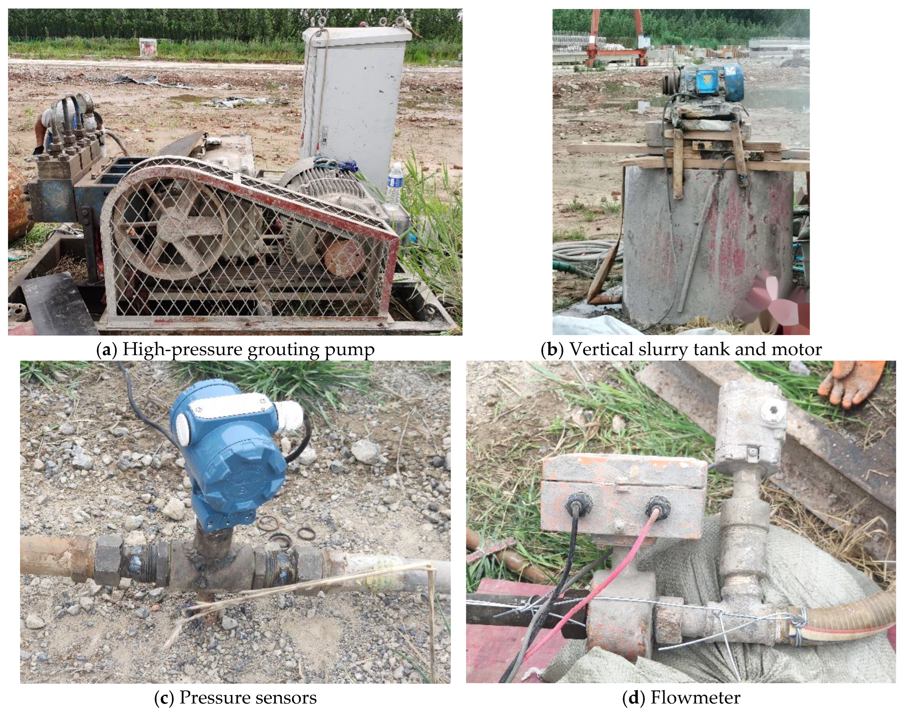
4.1. Material and Equipment

The grouting material used was 32.5 ordinary cement, commonly employed in grouting engineering. The strata in the site mainly comprise silt, silty clay, clay, and silty sand. The research was carried out in an area with similar soil layer characteristics to meet the assumptions of homogeneity and isotropy. Table 1 lists the basic physical parameters of the grouting material.
The grouting system consists of a GPB-90 high-pressure pump, a slurry pump, a vertical slurry tank, and a pressure sensor. The high-pressure pump and the slurry pump were used for pumping the Newtonian fluid and slurry, respectively. Figure 4 and Figure 5 show a diagram and physical images of the grouting device.

4.2. Test Design

In the grouting process in this experiment, the self-rotating grouting nozzle was used, and the grouting method of high-pressure disturbance followed by grouting was adopted. An orthogonal experiment with four factors and four levels was conducted, detailed in Table 2. Based on the study of Njock and Li [26,27], it was determined that the W/C ratio should range from 0.8 to 1.5. The grouting pressure was determined based on Zhou and Wan’s research [4,28], who mentioned that the grouting pressure on post-grouting stabilization ranges from 0 to 4 MPa. During the test, the outdoor and water temperatures for preparing the cement slurry were approximately 20 °C. The grouting pipe used in the tests has a 36 mm diameter, with three nozzles, each 2 mm in diameter, and a liquid flow rate Q of 0.05 m3/min.
“Disturb before grouting” refers to a technique where the soil at the bottom of the pile was first loosened using a high-pressure water jet directed through the self-rotating nozzle. After this loosening, the cement slurry was then filled into the disturbed soil by static pressure grouting. After 28 days of curing, the CCJG was excavated, scanned, and modeled, with 3ds Max 2018 version used to determine the volume of the resulting model. Subsequently, coring was carried out on the CCJG, followed by the uniaxial compressive strength test, which was conducted using a uniaxial compressive strength testing machine.

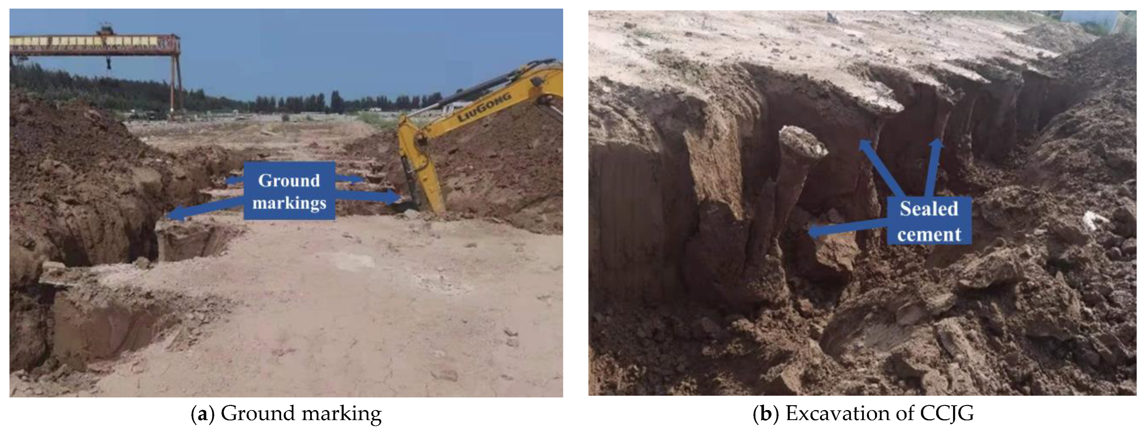
4.3. Test Implementation

Sixteen sets of grouting holes, each with a diameter of 0.2 m and a depth of 1.8 m, were established in a 14 × 6 m rectangular area on the site. The spacing between each grouting hole longitudinally and laterally was 2 m. The installation of the equipment into each test hole is shown in Figure 4 and followed the specifications technical code for building pile foundation JGJ94-2008 [29]. The disturbance and grouting were carried out after the completion of the maintenance of the cast-in-place pile. The parameters used in the test are shown in Table 2. The CCJG, formed post-grouting, was excavated after 28 days (Figure 6a), and the resulting CCJG were sequentially packaged and numbered.
According to Engineering rock mass test method standard GB/T50266-2013 [30], the specimen size was determined to be a cylinder with a diameter of 50 mm and a height of 100 mm, as shown in Figure 7a. Uniaxial compressive strength was measured for each specimen using a universal experimenter, as shown in Figure 7b.

4.4. Result and Discussion

The CCJG was scanned using a high-quality camera and modeled. A model of the CCJG is shown in Figure 8b. It can be seen that the CCJG was formed of slurry and soil, and the shape was an irregular round cake.
The diameters of the G02, G05, and G12 specimens in the XYZ directions were measured, and the calculated values were obtained using Equations (1)–(13). The calculated values were slightly lower than the actual values, and the error was within 8%. Hence, the formula for calculating the CCJG diameter corresponds reasonably with the actual conditions, as demonstrated in Table 3. The volume of CCJG and the uniaxial compressive strength measured by the orthogonal test are shown in Table 4.

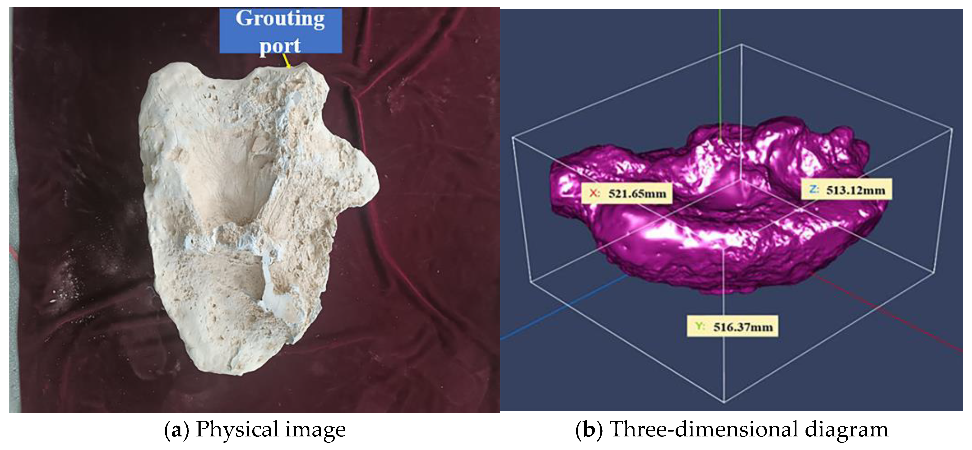
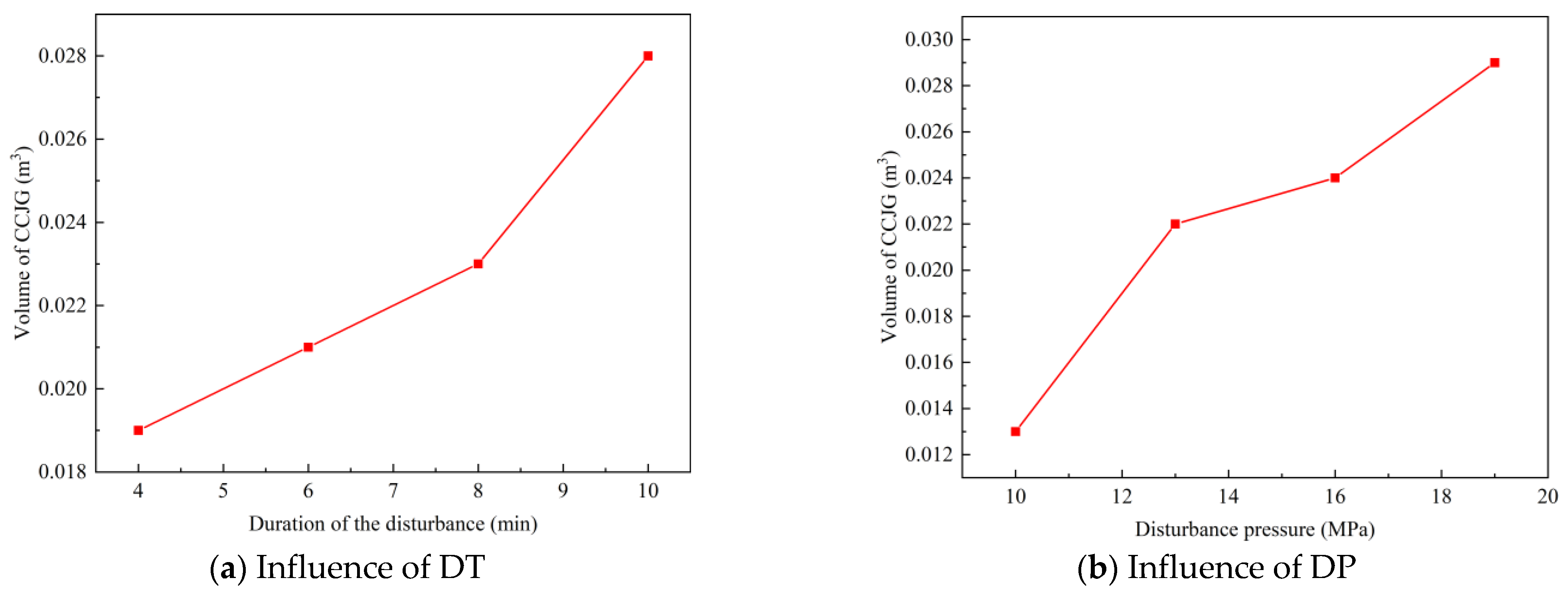
4.4.1. Influence of Grouting Parameters on the Volume of the CCJG

In Zhao’s study [21], a model test was conducted to examine the effects of different volumes of tip grouting on the load displacement behavior of the piles; the result showed that the greater the amount of grouting, the stronger the bearing capacity of the pile. Figure 9 illustrates the volume of the CCJG under various grouting parameters, with the variance analysis presented in Table 5. To determine the primary influence of each test factor, a range analysis of the orthogonal array test data was conducted. K is the average value of the sum of the test results of each factor at various levels, and its magnitude can determine the optimal level of each factor. R is the range of the various factors, and the magnitude of the R value indicates the degree of influence a factor has on the test index, with a larger R value signifying a greater impact.
Table 5 reveals that the DP significantly affects the volume of the CCJG, more so than the DT, GP, and W/C. The most effective combination was a DP of 19 MPa, a GP of 1 MPa, a DT of 10 min, and a W/C of 1.2 (A4B2C4D3), with which the volume of the CCJG was maximized. As with other studies, the volume of the CCJG increases with a rise in the GP and grout cement content, and the strength of the CCJG is enhanced with an increase in the cement content within the grout [31,32].
Figure 9 indicates that the volume of the CCJG grows with an increase in the DP. At a DP of 10 MPa, the average volume of the CCJG is 0.013 m3, expanding to 0.029 m3 when the DP reaches 19 MPa. This expansion occurs because high-pressure water disrupts the soil’s original structure, transforming it from a solid into a flowable slurry. The CCJG forms differently (through mixing replacement) in the disturbed area during grouting.
An increase in the DT also leads to a larger CCJG. A prolonged DT enhances the mixing effect of the high-pressure water jet on the soil. As a result, a more extensive CCJG forms due to improved permeation and grouting processes. The experimental observations indicated, however, that the volume increase was negligible when the DT was less than 8 min, suggesting that an excessively short DT might not yield the desired volume of the CCJG.

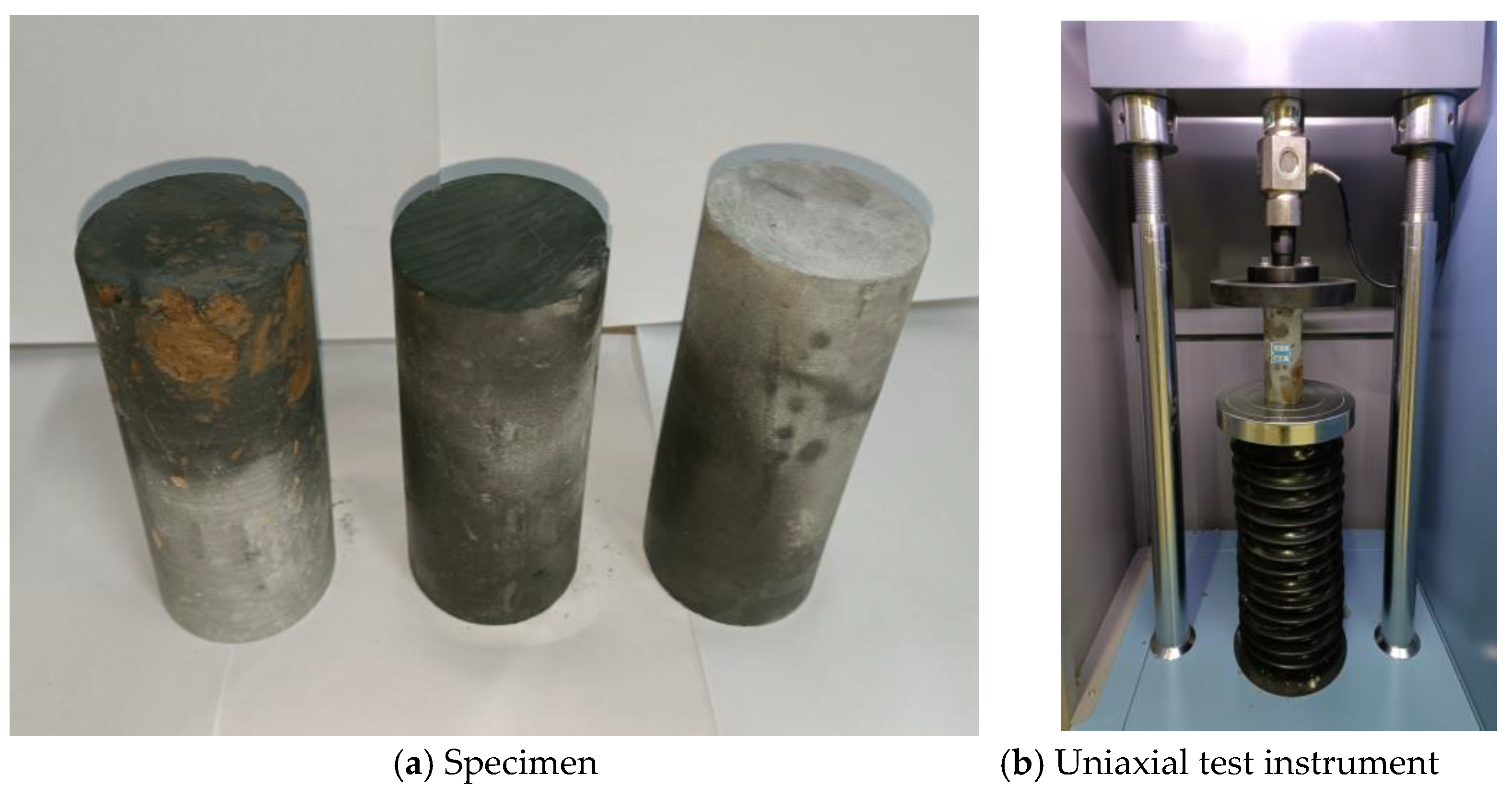
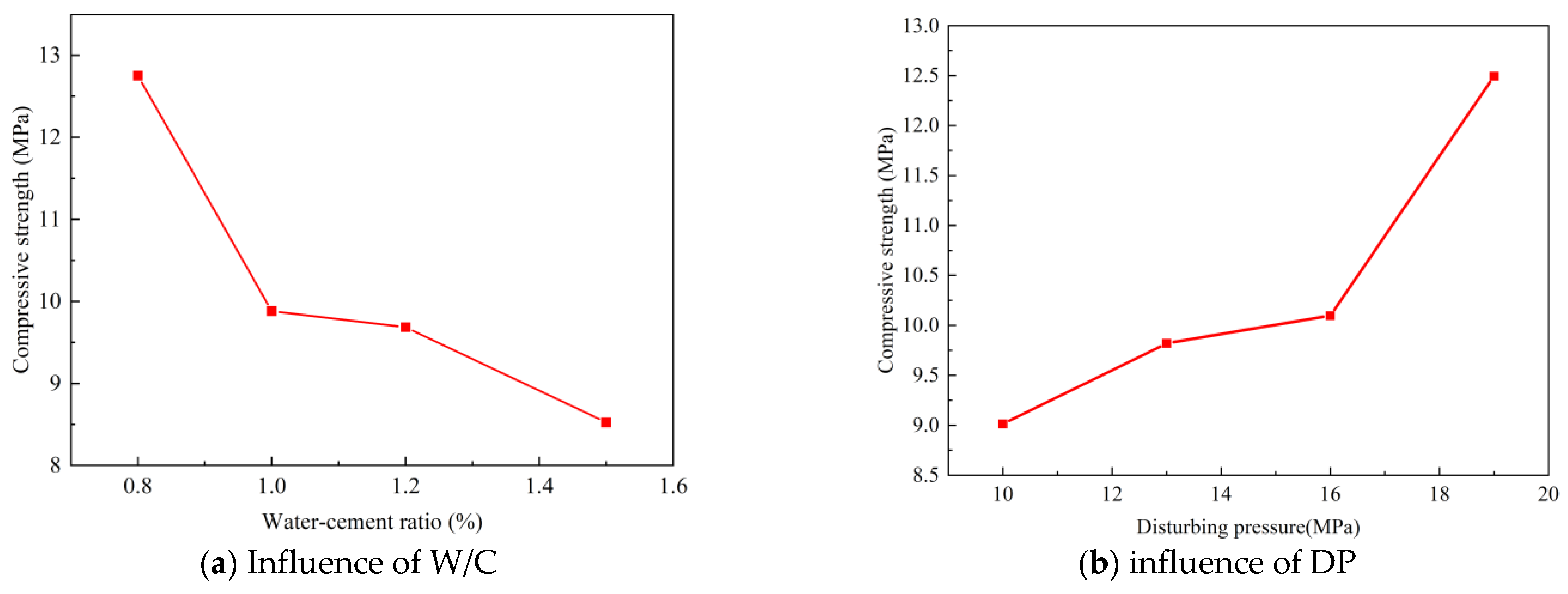
4.4.2. Influence of the Grouting Parameters on the Compressive Strength of the CCJG

Figure 10 presents the uniaxial compressive strength results for the CCJG under different grouting parameters, and the analysis is shown in Table 5.
From Table 6, the W/C has the most significant impact on the compressive strength of the CCJG, followed by the DT and DP. In contrast, GP exerts a lesser influence on its compressive strength than the other factors. Therefore, the effects of the W/C and DP on compressive strength warrant closer attention. The optimal test combination is A4B3C4D1, featuring a DP of 19 MPa, a static GP of 1.5 MPa, a DT of 10 min, and a W/C of 0.6.
Figure 10 illustrates that the compressive strength of the CCJG diminishes with an increase in the W/C, a phenomenon intricately linked to the variations in the cement concentration within the CCJG. Post-grouting, the interstices among the soil particles become inundated with cement slurry. As the cement slurry undergoes continuous hydration, the crystals expand rapidly, intermingling with the soil particles to establish a unique cement –soil framework. A lower W/C ratio correlates with augmented compressive strength of the CCJG under identical conditions.
Furthermore, the experimental findings suggest an enhancement in the compressive strength of the CCJG concomitant with a rise in the DP. This improvement was ostensibly due to a higher DP ensuring a more uniform distribution of particles within the slurry and a consequent reduction in defects. Consequently, this elevated the strength of the CCJG. Existing research shows that the UCS increases with an escalating grouting pressure, and the uniaxial compressive strength of a pile is correlated with the cement/soil ratio [33,34].

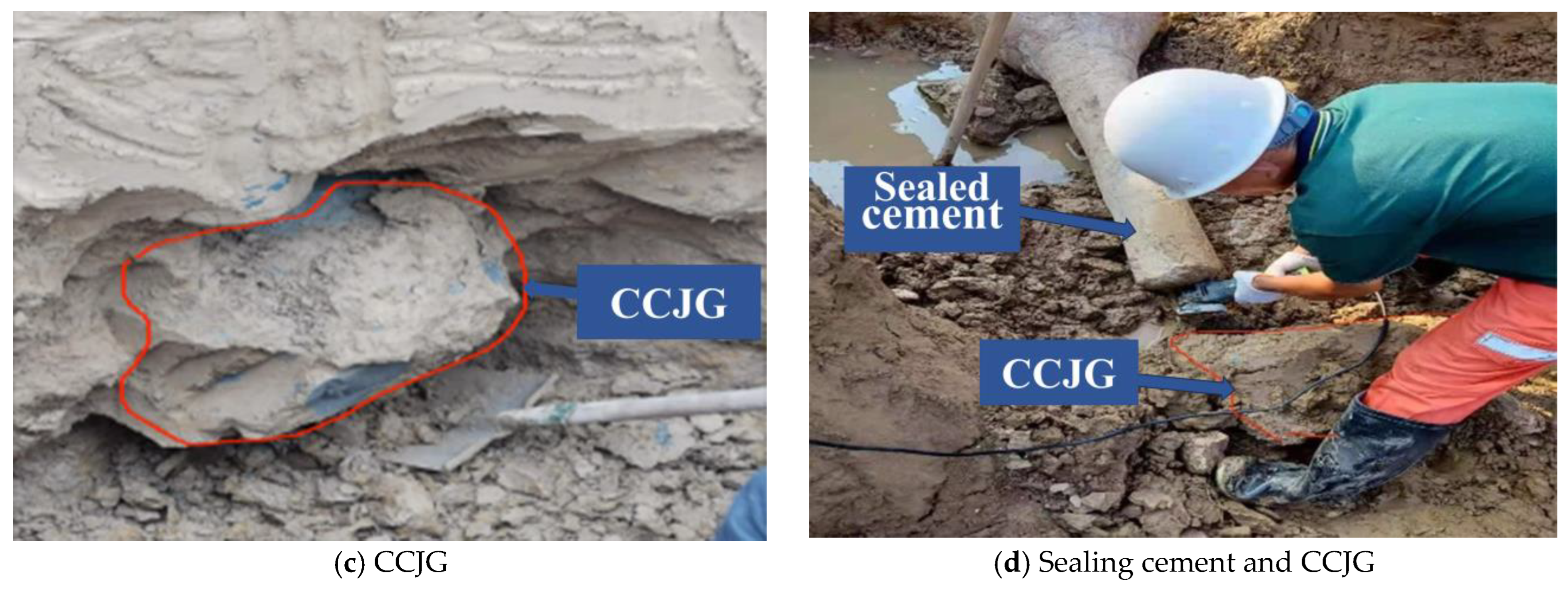
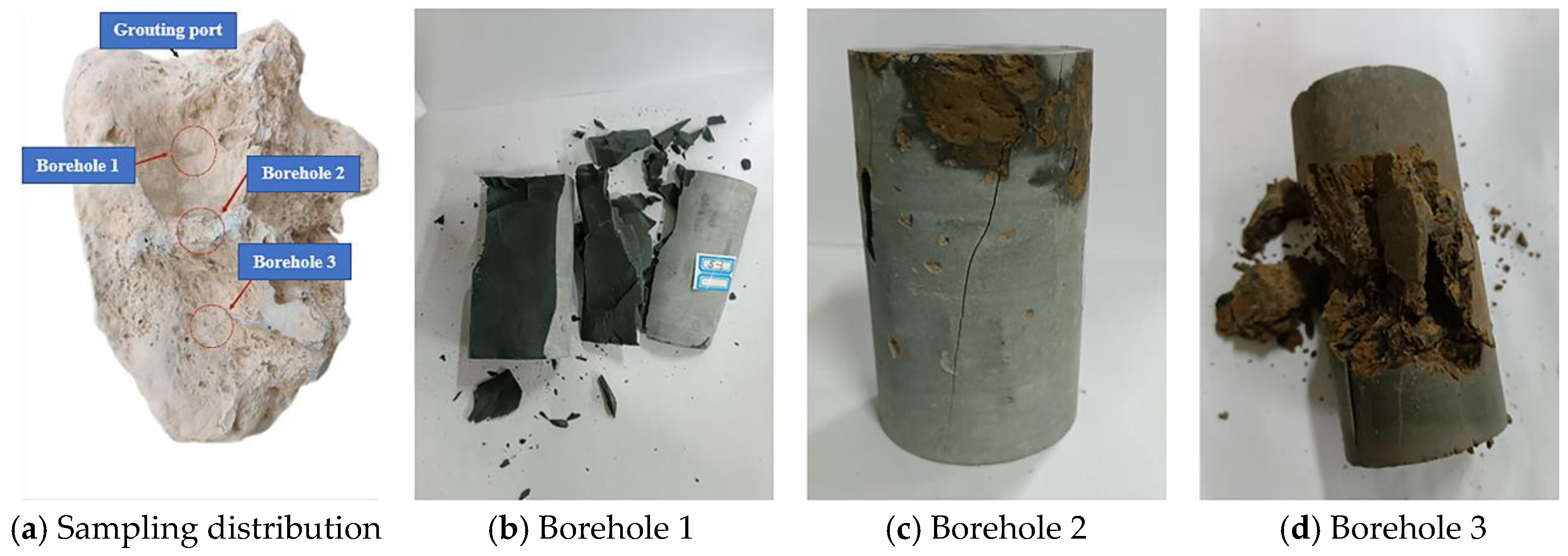
4.4.3. Analysis of the Grouting Diffusion Law of Self-Rotary Jet Grouting

This study further explored the diffusion law under high-pressure disturbance–grouting conditions, analyzing the strength of the core samples from varied locations within the CCJG. The coring sites and their associated failure modes are depicted in Figure 11.
Figure 11b–d indicate that the samples from borehole 1 are predominantly composed of cement. In contrast, those from borehole 2 exhibit a substantial cement proportion (the gray segment), interspersed with a few clods enveloped by cement. However, borehole 3’s samples exhibit a relatively lower cement content, displaying uniformity between the soil and cement. During static grouting, the cement slurry supplants the mud in the disturbed area, with the soil in the central region being displaced by cement. Therefore, it can be inferred that the stabilization method of the CCJG can be characterized according to three parts: replacement, mixing, and compaction. In the central area, the soil replacement is discernible, based on the compressive strength failure surface outcomes. In the outer area of the core, the soil and slurry are mixed evenly using grouting. And in the outermost area, due to high pressure, the soil is compacted.
However, some limitations should be noted. First, we did not conduct on-site testing to validate the accuracy of the climb height due to limited on-site conditions. We believe that these parameters have been derived and applied logically. Secondly, we ignored microstructural study of the CCJG; we will consider including an additional analysis in the future to provide a more comprehensive understanding of our findings.

5. Conclusions

  • This study introduced a theoretical model for estimating the diameter of the CCJG in high-pressure jet grouting. Field tests corroborated the formula’s applicability. In addition, a formula for computing the grout’s climb height on the pile side was derived, grounded in the rheological equation for a Newtonian fluid.
  • An optimization experiment for the grouting parameters was conducted, analyzing the impact of pivotal grouting parameters like the DP, DT, GP, and W/C on the CCJG’s volume and strength. It was established that DP and DT are the principal determinants of the CCJG’s volume. The largest CCJG volume materializes at a DP of 19 MPa and a DT of 10 min. Conversely, the W/C and DT predominantly influence the CCJG’s strength, with the peak strength occurring at a W/C of 0.6 and a DT of 10 min.
  • The dynamics of grout diffusion were scrutinized through compressive strength tests on core samples from the CCJG. The tests revealed varying stabilization forms of grout in the soil during the grouting process, with the slurry diffusing outward from the grouting hole’s center, stabilizing the soil through replacement, mixing, and compaction.

Author Contributions

The division of labor in this article: Conceptualization, Z.R. and C.G.; methodology, Q.G.; validation, G.C.; writing—original draft preparation and visualization, Y.X.; writing—review and editing, J.Z.; supervision, C.L.; project administration, D.W. All authors have read and agreed to the published version of the manuscript.

Funding

This study did not receive any specific funding from agencies in the public, commercial, or non-profit sectors.

Data Availability Statement

The original contributions presented in the study are included in the article, further inquiries can be directed to the corresponding author.

Conflicts of Interest

The authors declare no conflict of interest.

Abbreviation

SymbolMeaning
Dpdiameter of the CCJG
xLlimit of the cutting radius
ηaamplification factor when considering compaction grouting
vooutlet velocity of the high-pressure water at nozzle position
dnozzle diameter
vLcritical failure velocity of the soil
Pninlet pressure at nozzle position
γweight of the liquid
ggravitational acceleration
μflow velocity coefficient of the nozzle
Patmstandard atmospheric pressure
βcharacteristic velocity, with a value range of 1.5 to 3.0
q u soil mass resistance
σ’effective stress
φeffective friction angle
Ppumping pressure
Rdiameter of the CCJG after compaction
Irrigidity index, with a value range of 10 to 40
vPoisson’s ratio
Eelastic modulus
ccohesion
qinitial stress in the soil
k0lateral pressure coefficient
τcompressive stress
ηdynamic viscosity
λcompressive rate
rthickness of the microelement
r0radius of the pile
r1distance from the center of the pile to the edge of the circular slurry
Ppressure at the bottom of the microelement section
dppressure difference in the microelement section
γgslurry weight
K0static lateral pressure coefficient of the soil around the pile
γmaverage unit weight of the soil above the maximum climb height of the slurry
Llength of the pile
Lgclimb height of the slurry
Pbgrouting pressure on the pile side
Pcsplitting pressure at the pile–soil interface
Qgrout flow rate

References

  1. Ruan, W.J. Research on diffusion of grouting and basic properties of grouts. Chin. J. Geotech. Eng. 2005, 27, 69–73. [Google Scholar]
  2. Yang, M.J.; Chen, M.X.; He, Y.N. Current research state of grouting technology and its development direction in future. Chin. J. Rock Mech. Eng. 2001, 20, 839–841. [Google Scholar]
  3. Wu, Y.; Zhang, X.F.; Zhao, C.; Zhao, C.F. Effects of soil unloading and grouting on the vertical bearing mechanism for compressive piles. Ocean. Eng. 2023, 271, 113754. [Google Scholar] [CrossRef]
  4. Wan, Z.H.; Dai, G.L.; Gong, W.M. Field study on post-grouting effects of cast-in-place bored piles in extra-thick fine sand layers. Acta Geotech. 2019, 14, 1357–1377. [Google Scholar] [CrossRef]
  5. Hu, H.B.; Jin, Q.Q.; Yang, F.; Zhou, J.J.; Ma, J.J.; Gong, X.N.; Guo, J. A novel method for testing the effect of base post-grouting of super-long piles. Appl. Sci. 2022, 12, 10996. [Google Scholar] [CrossRef]
  6. Qiu, J.L.; Liu, H.Q.; Lai, J.X.; Lai, H.P.; Chen, J.X.; Wang, K. Investigating the long-term settlement of a tunnel built over improved loessial foundation soil using jet grouting technique. J. Perform. Constr. Facil. 2018, 32, 04018066. [Google Scholar] [CrossRef]
  7. Shen, S.L.; Wu, H.N.; Cui, Y.J.; Yin, Z.Y. Long-term settlement behaviour of metro tunnels in the soft deposits of Shanghai. Tunn. Undergr. Space Technol. Inc. Trenchless Technol. Res. 2014, 40, 309–323. [Google Scholar] [CrossRef]
  8. Sandra, C.; António, V.D.F.; Duílio, C.; Nuno, A. The use of drilling parameters recording as a tool for quality control in jet grouting treatments. In Proceedings of the International Conference on Grouting and Deep Mixing, New Orleans, LA, USA, 15–18 February 2012; Volume 25, pp. 1484–1493. [Google Scholar]
  9. Zhao, L.S.; Qi, X.H.; Tan, F.; Chen, Y. A new prediction model of the jet grouting column diameter for three jet grouting systems. Comput. Geotech. 2023, 163, 105753. [Google Scholar] [CrossRef]
  10. Zhang, L.Z.; Yu, R.G.; Zhang, Q.S.; Liu, R.T.; Feng, H.J.; Chu, Y.T. Permeation grouting diffusion mechanism of quick setting grout. Tunn. Undergr. Space Technol. Inc. Trenchless Technol. Res. 2022, 6, 124. [Google Scholar] [CrossRef]
  11. Bayesteh, H.; Sabermahani, M. Field study on performance of jet grouting in low water content clay. Eng. Geol. 2020, 264, 105314. [Google Scholar] [CrossRef]
  12. Yang, Z.Q.; Hou, K.P.; Guo, T.T.; Ma, Q. Study on penetration grouting mechanism based on Bingham fluid of time-dependent behavior. J. Sichuan Univ. Eng. Sci. Ed. 2011, 43, 67–72. [Google Scholar]
  13. Yang, Z.Q.; Hou, K.P.; Liang, W.; Cheng, Y.; Yang, B.J. Study of diffusion parameters of Newtonian fluid based on column-hemispherical penetration grouting. Rock Soil Mech. 2014, 35, 17–24. [Google Scholar]
  14. Yang, Z.Q.; Niu, X.D.; Hou, K.P.; Guo, Y.H.; Liang, W.; Zhou, Z.H. Column penetration grouting mechanism researches based on Power-law fluid. J. Harbin Inst. Technol. 2016, 48, 178–183. [Google Scholar]
  15. Li, S.C.; Zhang, W.J.; Zhang, Q.S.; Zhang, X.; Liu, R.T.; Pan, G.M.; Li, Z.P.; Che, Z.Y. Research on advantage-fracture grouting mechanism and controlled grouting method in water-rich fault zone. Rock Soil Mech. 2014, 35, 744–752. [Google Scholar]
  16. Sun, F.; Zhang, D.L.; Chen, T.L. Fracture grouting mechanism in tunnels based on time-dependent behaviors of grout. Chin. J. Geotech. Eng. 2011, 33, 88–93. [Google Scholar]
  17. Ding, Y.; Yang, Z.Q.; Yang, Y.; Zhu, Y.Y.; Guo, Y.F.; Zhang, J.; Chen, X.G. Study on penetration grouting mechanism based on Newton fluid of time-dependent behavior of rheological parameters. Shock Vib. 2020, 2020, 8811028. [Google Scholar] [CrossRef]
  18. Ye, F.; Gou, C.F.; Liu, Y.P.; Sun, H.D. Half-spherical surface diffusion model of shield tunnel back-filled grouts. J. TongJi Univ. Nat. Sci. 2012, 40, 1789–1794. [Google Scholar]
  19. Sun, Q. Theoretical Analysis Research on the Effect of Jet in the Soft Soil Layer. Master’s Thesis, JiLin University, Changchun, China, 2017. [Google Scholar]
  20. Dai, G.L.; Wan, Z.H.; Zhu, M.X.; Gong, W.M. The model of grout migration height for pressured grouting at pile tip based on time-dependent behavior of viscosity and its engineering application. Rock Soil Mech. 2018, 39, 2941–2950. [Google Scholar]
  21. Zhao, C.F.; Wu, W.; Zhao, C.; Wang, Y. Load-Displacement Relationship of Single Piles in Clay Considering Different Tip Grouting Volumes and Grouting Returned Heights. ASCE 2020, 20, 04019158. [Google Scholar] [CrossRef]
  22. Han, L.Z.; Wang, Z.F. Practical method to predict diameter of jet grout column by double fluid system. China J. Highw. Transp. 2019, 32, 128–134. [Google Scholar]
  23. Fang, K. Grout-Soil Interaction during Base Grouting and Its Effects on the Behavior of Grouted Piles. Ph.D. Thesis, ZheJiang University, Hangzhou, China, 2013. [Google Scholar]
  24. Zhang, S.S.; Wang, C.; Ge, T. Experimental prediction of the noncontact jet Trencher’s excavation depth in clay. Mar. Georesour. Geotechnol. 2017, 35, 300–304. [Google Scholar] [CrossRef]
  25. Shen, S.L.; Njock, P.G.A.; Zhou, A.N. Influence of nozzle structure on effectiveness of jet grouting operations and its optimal design. Geoenergy Sci. Eng. 2023, 226, 211788. [Google Scholar] [CrossRef]
  26. Njock, P.G.A.; Chen, J.; Giuseppe, M.; Arul, A.; Yong, H.K. A review of jet grouting practice and development. Arab. J. Geosci. 2018, 11, 459–480. [Google Scholar] [CrossRef]
  27. Li, Z.P.; Zhang, L.Z.; Zhang, Q.S.; Liu, R.T.; Yang, W.D.; Chu, Y.T. Simulation test for permeation grouting reinforcement effect of sand layer. J. China Coal Soc. 2018, 43, 3488–3497. [Google Scholar]
  28. Zhou, Z.J.; Xu, F.; Lei, J.T.; Bai, Y.; Chen, C.R.; Xu, T.Y.; Zhang, Z.P.; Zhu, L.X.; Liu, T. Experimental study of the influence of different hole-forming methods on the bearing characteristics of post-grouting pile in Loess Areas. Transp. Geotech. 2021, 21, 100423. [Google Scholar] [CrossRef]
  29. JGJ94-2008; The Specifications Technical Code for Building Pile Foundation in China. Ministry of Housing and Urban-Rural Development of the People’s Republic of China: Beijing, China, 2008.
  30. GB/T50266-2013; Engineering Rock Mass Test Method Standard in China. Ministry of Housing and Urban-Rural Development of the People’s Republic of China: Beijing, China, 2013.
  31. Babak, N.; Ahangari, K. Field study of the influence of various jet grouting parameters on soilcrete unconfined compressive strength and its diameter. Int. J. Rock Mech. Min. Sci. 2010, 47, 685–689. [Google Scholar]
  32. Wang, G.S.; Hong, B.N.; Liu, X.; Sun, D.N.; Shao, Z.W.; Yao, Y.L. Experimental study on the shear properties of soil around piles with permeation grouting. Appl. Sci. 2023, 13, 621. [Google Scholar] [CrossRef]
  33. Babak, N.; Morteza, O. Effect of grout pressure and grout flow on soil physical and mechanical properties in jet grouting operations. Int. J. Rock Mech. Min. Sci. 2009, 46, 498–505. [Google Scholar]
  34. Modoni, G.; Wanik, L.; Mascolo, M.C.; Salvatore, E.; Bao, W.J.; Shen, S.L.; Daniele, V.; Pingue, L. Strength of sandy and clayey soils cemented with single and double fluid jet grouting. Soils Found. 2019, 59, 942–954. [Google Scholar] [CrossRef]
Figure 1. The climb height model of Newtonian fluid.
Buildings 14 01491 g001
Figure 2. Diagram of self-rotating nozzle. ① High-pressure jet; ② nozzle; ③ self-rotating nozzle; ④ shell; ⑤ high-pressure water flow; ⑥ rotating central axis; ⑦ ball bearing; ⑧ housing; ⑨ thrust bearing; ⑩ “O”-type seal ring.
Buildings 14 01491 g002
Figure 3. Location of the field test site.
Buildings 14 01491 g003
Figure 4. Layout of grouting device. ① High-pressure pump; ② slurry pump; ③ flowmeter; ④ pressure sensor; ⑤ monitoring device; ⑥ high-pressure pipeline; ⑦ high-pressure elbow; ⑧ grouting nozzle; ⑨ soil mass; ⑩ cement sealing; ⑪ tamping soil; ⑫ CCJG.
Buildings 14 01491 g004
Figure 5. Physical diagram of a grouting test device.
Buildings 14 01491 g005
Figure 6. Field excavation of CCJG.
Buildings 14 01491 g006aBuildings 14 01491 g006b
Figure 7. Specimens with uniaxial test instrument.
Buildings 14 01491 g007
Figure 8. Three-dimensional model of the CCJG.
Buildings 14 01491 g008
Figure 9. The influence of DP and DT on the volume of CCJG.
Buildings 14 01491 g009
Figure 10. The influence of W/C and DP on the compressive strength of CCJG.
Buildings 14 01491 g010
Figure 11. Core distribution and core sample compressive failure.
Buildings 14 01491 g011
Table 1. Basic properties of grouting material.
Specific Gravity
Gs
Effective Stress at the Grouting Position
(kPa)
Angle of Internal Friction
(°)
1.8216.210
Table 2. Parameters of grouting test.
GradesFactors
DP (MPa)W/CGP (MPa)DT (min)
1100.80.54
2131.01.06
3161.21.58
4191.52.010
Table 3. Size difference of CCJGs.
Calculated Value (m)Average of Actual Value (m)The Error (%)
Diameter of the G020.4760.5167.7%
Diameter of the G050.5570.5966.5%
Diameter of the G120.6070.6516.8%
Table 4. Volume and strength of CCJGs.
No.Influence FactorsTest Results
DP
(MPa)
W/CGP
(MPa)
DT
(min)
Volume
(m3)
Strength
(MPa)
G01100.80.540.0057.9
G02101.02.080.01510.4
G03101.21.0100.02312.7
G04101.51.560.0088.5
G05130.81.060.0237.5
G06131.01.5100.02713.8
G07131.20.580.02212.6
G08131.52.040.0176.9
G09160.81.580.0259.1
G10161.01.040.0207.1
G11161.22.060.02211.6
G12161.50.5100.0298.7
G13190.82.0100.03411.7
G14191.00.560.02810.5
G15191.21.540.02314.3
G16191.51.080.03010.7
Table 5. Analysis of CCJG volume difference.
FactorABCD
DP (MPa)GP (MPa)DT (min)W/C
K - - 10.0130.0210.0190.022
K - - 20.0220.0240.0210.023
K - - 30.0240.0210.0230.023
K - - 40.0290.0230.0280.022
R0.0160.0030.0090.001
Optimal level4243
Best matchA4B2C4D3
OrderDP > DT > GP > W/C
Table 6. Analysis table of uniaxial compressive strength range of CCJG.
FactorsABCD
DP
(MPa)
GP
(MPa)
DT
(min)
W/C
(%)
K - - 19.0149.8878.99212.752
K - - 29.8209.3599.4929.884
K - - 310.09811.35010.4419.686
K - - 412.49410.75212.4248.526
R3.4801.9913.4324.226
Optimal level4341
Best matchA4B3C4D1
orderW/C > DT > DP > GP
Disclaimer/Publisher’s Note: The statements, opinions and data contained in all publications are solely those of the individual author(s) and contributor(s) and not of MDPI and/or the editor(s). MDPI and/or the editor(s) disclaim responsibility for any injury to people or property resulting from any ideas, methods, instructions or products referred to in the content.

