Article

Nonlinear Dynamic Response of Galfenol Cantilever Energy Harvester Considering Geometric Nonlinear with a Nonlinear Energy Sink

School of Civil Engineering and Architecture, Chongqing University of Science and Technology, Chongqing 401331, China
*
Authors to whom correspondence should be addressed.
Buildings 2024, 14(5), 1482; https://doi.org/10.3390/buildings14051482
Submission received: 31 March 2024 / Revised: 14 May 2024 / Accepted: 17 May 2024 / Published: 20 May 2024
(This article belongs to the Special Issue Building Foundation Analysis: Soil–Structure Interaction)

Abstract

:
The nonlinear energy sink (NES) and Galfenol material can achieve vibration suppression and energy harvesting of the structure, respectively. Compared with a linear structure, the geometric nonlinearity can affect the output performances of the cantilever beam structure. This investigation aims to present a coupled system consisting of a nonlinear energy sink (NES) and a cantilever Galfenol energy harvesting beam with geometric nonlinearity. Based on Hamilton’s principle, linear constitutive equations of magnetostrictive material, and Faraday’s law of electromagnetic induction, the theoretical dynamic model of the coupled system is proposed. Utilizing the Galliakin decomposition method and Runge–Kutta method, the harvested power of the external load resistance, and tip vibration displacements of the Galfenol energy harvesting model are analyzed. The influences of the external excitation, external resistance, and NES parameters on the output characteristic of the proposed coupling system have been investigated. Results reveal that introducing NES can reduce the cantilever beam’s vibration while considering the geometric nonlinearity of the cantilever beam can induce a nonlinear softening phenomenon for the output behaviors. Compared to the linear system without NES, the coupling model proposed in this work can achieve dual efficacy goals over a wide range of excitation frequencies when selecting appropriate parameters. In general, large excitation amplitude and NES stiffness, small external resistance, and small or large NES damping values can achieve the effect of broadband energy harvesting.

1. Introduction

With the development of micro-electro-mechanical devices towards miniaturization, intelligence, wireless, and low power consumption, traditional chemical battery power supply methods are no longer applicable. Therefore, thanks to the priorities of high energy conversion efficiency, easy miniaturization, and strong applicability utilizing smart materials to transform ambient mechanical energy into usable electrical energy has become the current research focus for scholars. The harvested electric energy can power low-power online monitoring and sensing devices in practical engineering, such as vehicle tracking, structural health monitoring, environmental monitoring, intelligent building, and aerospace fields [1,2,3]. In the literature, several energy harvesting mechanisms have been introduced to transform such vibration energy into electricity, for instance, electrostatic [4,5], electromagnetic [6,7], piezoelectric [8,9,10,11,12], and magnetostrictive [13,14].
The magnetostrictive vibration energy harvester has attracted growing attention thanks to its peculiar properties. For instance, high magnetostriction, high permeability, small brittleness, high tensile strength, and a wide working temperature range are reported in the previous works [2,15]. Through the inverse effect (Virari effect) of magnetostrictive materials, including Terfenol-D and Galfenol material, the vibration energy can be effectively transferred into electric energy by the magnetostrictive vibration energy harvester [16,17,18]. Compared to Terfenol-D, Galfenol has better magnetic and mechanical properties, namely, high magnetostriction and magnetic permeability, ideal tensile and compressive mechanical properties, and a wide operating temperature range [19,20,21,22]. These superior features of Galfenol make it more suitable for energy harvesting. Yoo and Flatau [18] established the mechanical equation of the lumped parameter model for the Galfenol cantilever beam harvester and the constitutive relationship of the magnetostrictive material. The output results of the proposed harvester had been tested by the indoor experiment. Cao et al. [23,24] developed a cantilever-based energy harvester using the Galfenol material and derived the nonlinear coupled dynamic equations for the designed energy harvester. The output performances of the proposed device were numerically calculated by the Newmark method and verified by the experimental data. Clemente et al. [25] presented a force-activated kinetic energy conversion device and analyzed the energy harvester’s output performances through experimental tests as well as FEM COMSOL Multiphysics simulation. Jin et al. [26] proposed a cylindrical wave energy harvester, of which the Galfenol sheet is chosen as the core material. The motion characteristics and the induction voltage of the Galfenol device were analyzed by theoretical derivation analysis, the ANSYS Workbench, as well as experimental tests. Wang et al. [15] established the electromechanically coupled model of the Galfenol-based cantilever energy harvester. In their work, the explicit analytical formulations of the output performances for the proposed energy harvesting model were obtained by the Galerkin decomposition method and electro-mechanical decoupling method.
Excessive structural vibration response will damage the structure; therefore, vibration suppression of structures has always been a hot research topic for global scholars and engineers. Due to the benefits of simple structure, broad operating frequency bandwidth, and great robustness, the nonlinear energy sink (NES) has attracted extensive focus from vibration control researchers [27,28]. The NES is a new kind of nonlinear dynamic absorber proposed by Vakakis [29] and Gendelman et al. [30] in 2001. Numerous investigations have proved that an NES with third-order nonlinear stiffness can remarkably reduce the vibration amplitude of the main vibration structure [31,32,33,34]. Recently, scholars have combined the NES and energy harvesters to achieve the dual efficacy goal, namely, vibration suppression and energy harvesting [35,36]. Kremer and Liu [37] studied the steady performances of the coupled system for an NES attached to an energy harvester by analytical and experimental methods. The study showed that the developed system can achieve dual efficacy goals in a broadband range. Xiong et al. [38] designed an NES-piezoelectric energy harvesting system. The mixed multi-scale and harmonic balance methods, as well as the Newton-Raphson harmonic balance method, were employed to analyze the nonlinear dynamic behavior and harvested power of the constructed coupling system. The results revealed that the coupled system could decline the vibration from the main structure and harvest energy in a wide frequency band. Tian et al. [39] coupled an energy-harvester-enhanced NES system into the cantilever trapezoidal plate to control the aeroelastic behaviors of the plate and harvest the vibration energy. Compared to the system with only the NES, the suppression effect of the energy-harvester-enhanced NES has been demonstrated better. Zhang’s team conducted extensive research by integrating the NES and giant magnetostrictive material (GMM) to achieve vibration suppression and energy capture. The traditional NES [40] and lever-type NES [41] coupled by rod-type GMM [42] and cantilever-type GMM [43] had been investigated for application in the one degree of freedom primary system [44], two degrees of freedom primary system [45], and aerospace industry [46].
In the current theories, the high-order terms in the first derivative of vibration displacement were generally ignored for the derivation of the energy harvesting model. Therefore, the influence of the geometric nonlinear characteristics of the cantilever beam on the free end motion was omitted [47]. A study was performed to discuss the relationship between structural size parameters and the features of cantilever-based piezoelectric energy harvesters by Tan et al. [48]. The results showed that once the wind speed surpasses a certain value, the geometric nonlinearity will significantly impact the output responses of the energy harvester. Li et al. [47] investigated the influence of geometric nonlinear characteristics on the dynamic response of the beam-mass-foundation system and concluded that larger errors were produced when the effect of the geometrical nonlinearity was neglected. According to the Euler-Bernoulli beam theory and the extended Hamilton principle, Shooshtari et al. [49] discussed the impacts of the geometric nonlinearity of the cantilever structure on the free vibration behaviors of the coupled energy harvesting system. The piezoelectric layer’s length was found to have a greater effect on the response of the analyzed system. Li et al. [50] discussed the effects of the dual nonlinear properties on the performances of the L-shaped harvester. It was concluded that with the increase in the excitation amplitude, the geometric nonlinearity will significantly impact the output features. Nie et al. [51,52,53,54] introduced the structure’s and piezoelectric materials’ geometric nonlinearities into the L-shaped piezoelectric energy harvester. The analysis indicated that the energy harvester with the geometric nonlinearities considered could harvest power more efficiently with a reduced vibration displacement over a wider frequency bandwidth.
From the above previous literature, we can find that considering geometric nonlinear effects can enhance the prediction exactitude of the output properties of the energy harvester, especially for large-amplitude vibrations and high electric field conditions. Combining NES and energy harvesting modules can simultaneously achieve both vibration reduction and energy harvesting. As a new type of magnetostrictive material, Galfenol has become a particularly promising transducer material due to its excellent characteristics and is gradually being applied in vibration energy harvesting. In our previous work, the research focus was more on introducing geometric nonlinearity into piezoelectric energy harvesters [51,52,53,54]. In 2023, based on Galfenol materials, we proposed a magneto-electric energy harvester without taking into account the cantilever structure’s geometric nonlinearity [15]. To the best of the authors’ knowledge, there have been no reports on the simultaneous introduction of NES and geometric nonlinearity into the Galfenol energy harvester. Therefore, an electromechanically coupled system integrated by the NES and Galfenol energy harvester with geometric nonlinearity considered is introduced in this work. For various structures in engineering, the prerequisite for analyzing the performance impact mechanisms is to establish more accurate static and dynamic models. For example, Han et al. [55,56,57] improved the efficiency and accuracy of analyzing bearing systems by establishing and modifying nonlinear dynamic models of bearing systems. Wang et al. [58] constructed the kinematic model of a bistable origami flexible gripper based on the relationship between crease angles and unfolding angles in auxiliary spherical triangles to analyze and improve the grabbing capacity. Then the drawbacks of traditional gripper models, such as slow response speed and low grasping efficiency, were settled. Therefore, to analyze the output characteristic of the proposed coupling system, the electromechanically coupled dynamic equations of the proposed coupling system are first established according to the Hamiltons principle, the linear constitutive relationships of Galfenol materials, and Faraday’s law of electromagnetic induction. The Galerkin approximation is adopted for separating the time and displacement variables, and the Runge-Kutta method is used to analyze the output performances of the linear and nonlinear coupled systems. In addition, the influences of various parameters of the designed system on the output responses are explored. Through parameter analysis, it is revealed that the proposed coupled model can realize the dual effect goals of vibration suppression and energy capture when the model parameters are set in a certain range.

2. Mathematical Model

As illustrated in Figure 1, the proposed cantilever vibration suppression and energy harvesting system, which is referred to as the NES-Galfenol coupled system, consists of two main components: the cantilever energy harvesting system and the NES system. The cantilever energy harvesting system is composed of an aluminum and Galfenol composite cantilever beam wrapped with coils, a lumped mass, and an external circuit. Note that the structural aluminum layer of the composite cantilever is bounded by a Galfenol sheet and tightly wound with a coil. Besides, the lumped mass M is fixed at the end of the composite cantilever beam, and an external circuit is connected to each end of the coil. It should be pointed out that, as plotted in Figure 1, the fixed end of the cantilever structure can be considered as the elastic foundation. Then the proposed NES-Galfenol-coupled system can be treated as a cantilevered beam-like structure laying on an elastic foundation and can be modeled by the Winkler spring model. The NES system is comprised of a lightweight lumped mass, a viscous damping, and a spring with cubic nonlinear stiffness. Under the external harmonic base excitation, as the composite cantilever beam vibrates, the magnetic induction intensity of the coil will alter, benefiting from the inverse magnetostriction effect. Then an induced current is produced in the coil based on Faraday’s law of electromagnetic induction. As a consequence, the vibration energy will finally be converted to electrical energy by the Villari effect of the Galfenol layer and dissipated by the NES. It was noted that the introduction of the NES system can dissipate the vibration energy transmitted from the base and protect the structure of the cantilever energy harvesting system. This means that the model proposed in this work can achieve the dual-effect goal of reducing vibration transmitted from the base (main structure) and capturing the abandoned vibration energy. Additionally, the continuous green and environmentally friendly electrical energy harvested by the cantilever energy harvesting system can provide power to low-power electronic devices. These electronic devices have broad application prospects in structural health detection of transmission towers, building structures, and bridge structures, vehicle tracking on roads, and indoor and outdoor environmental monitoring.

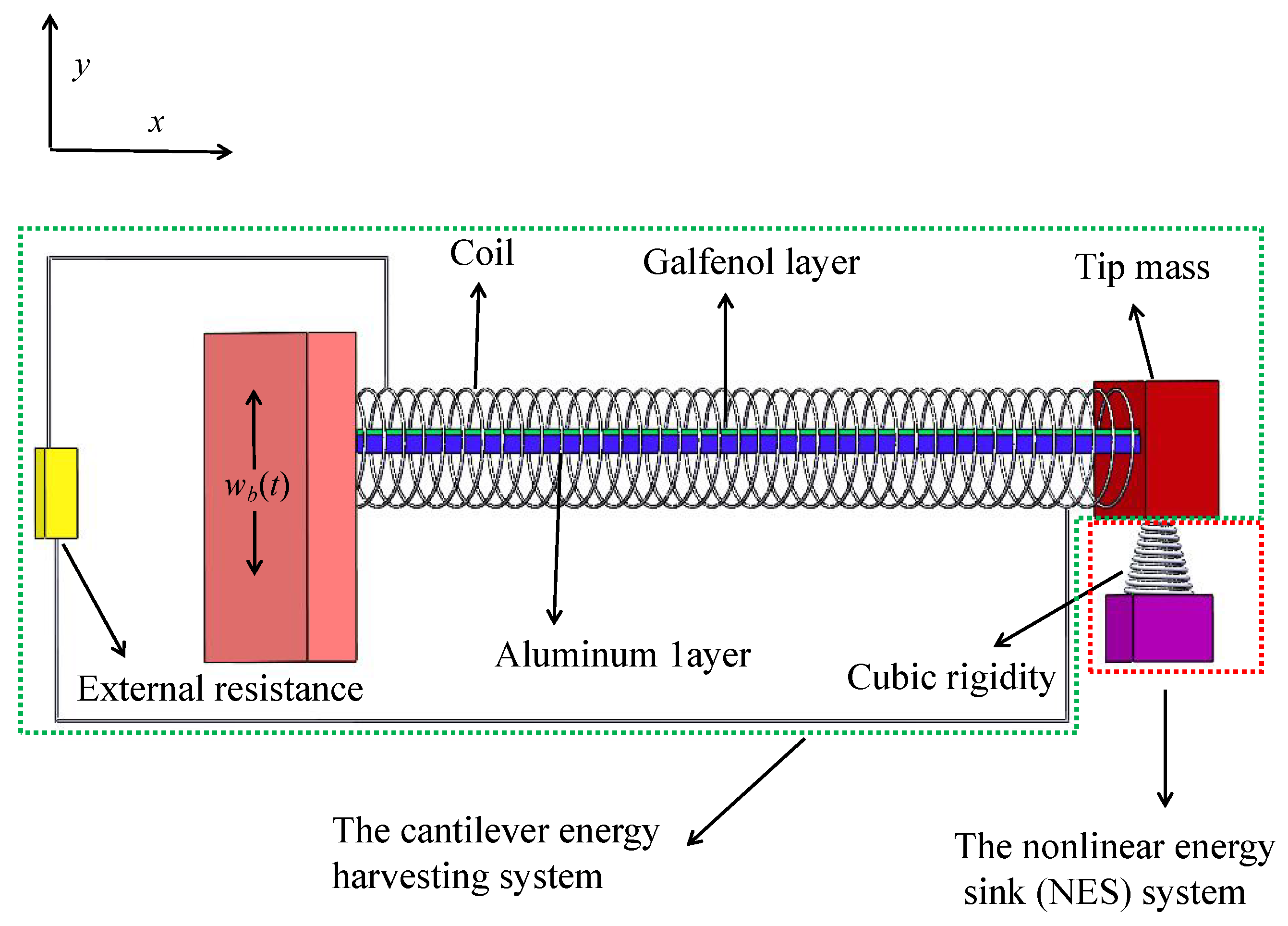
2.1. Coupled Mechanical Equations of the Cantilever Energy Harvesting System

To obtain the nonlinear electromechanical-coupled governing equations of the cantilever energy harvesting system for the coupled model, the extended Hamilton’s principle [51] is utilized as
t 1 t 2 δ T δ V + δ W n c d t = 0
where T, V, and W n c are respectively the kinetic energy, potential energy, and virtual work done by the nonconservative forces of the energy harvester model. It is worth noting that the cantilever structure is regarded as a uniform composite beam, satisfying the Euler-Bernoulli beam assumption since the cantilever structure is designed as a considerably thin beam. Therefore, the shear effect and rotational inertia of the cantilever composite structure are ignored, and the cantilever structure always satisfies the plane section assumption during the vibration deformation process. Additionally, the Galfenol layer is assumed to be tightly tied to the structural layer, so the deformation of the two material layers remains coordinated. Based on the above assumptions, the kinetic energy T of the coupling system is written as
T = 1 2 0 L m u t 2 + w t + w b t 2 d x + 1 2 M u ( L ) t 2 + w L t + w b t 2 + 1 2 J 2 w L x t 2 + 2 w L x t 2 w L x 2
where m is the mass per unit length of the composite cantilever structure and given by m = b s h s ρ s + b m h m ρ m , of which ρ s , ρ m , b s , b m , h s , and h m are respectively the density, width, and thickness of the aluminum and the Galfenol layer. L is the total length of the composite cantilever beam. M and J are the mass and rotational inertia of the lumped mass. w ( x , t ) and u ( x , t ) are the transverse and axial vibration displacements of the cantilever beam at section x with respect to the fixed end of the cantilever structure, respectively. w b ( t ) is the harmonic vibration displacement of the base excitation. Note that w ( x , t ) , u ( x , t ) , and w b ( t ) are abbreviated as w, u, and w b in the subsequent content for convenience, respectively. Additionally, the effect of gravitational potential energy is neglected since it is relatively small in comparison with the elastic strain potential energy of the beam. To account for the geometric nonlinearities of the coupled system’s cantilever beam, the horizontal and vertical vibration velocities of both the beam and the lumped mass have been taken into consideration.
Assuming that the stress and strain of the structural layer follow Hooke’s law and the stress-strain of the Galfenol layer follows a linear constitutive equation [15], the potential energy V of the coupling system can be given by
V = 0 L E I 2 w x 2 2 + 2 w x 2 2 w x 2 d x
where E I is the elasticity stiffness of the composite cantilever beam and expressed as E I = 1 3 E s b s h b 3 h a 3 + 1 3 E m b m h c 3 h b 3 , of which E s and E m are the elasticity modulus of the aluminum layer and the Galfenol layer, and I is the cross-section inertia moment of the composite cantilever structure. h a = E m h m h m + E m h m h s / 2 E m h m + 2 E s h s + h s / 2 and h b = h s + h a are coordinates of the lower and upper boundaries for the aluminum layer, and h c = h s + h m + h a and h p c = h b + h c 2 are respectively the coordinates of the top and the neutral axis for the Galfenol layer.
According to Nie et al. [52], the geometrically nonlinear deformation relation of the transverse and axial vibration displacement for the cantilever beams can be denoted by w x , t = 0 x sin φ η , t d η , u x , t = 0 x cos φ η , t d η , of which, φ ( η , t ) represents the rotation angle of section η . Eliminating higher-order terms by Taylor expansion yields
u x , t = 0 x 1 1 2 w η , t 2 d η
d φ x , t d t = 2 w x , t x t 1 + 1 2 w x , t x 2
φ x , t x = = 2 w ( x , t ) x 2 1 + 1 2 w ( x , t ) x 2
It points out that the higher-order terms in Equations (4)–(6) are regarded as far less than one and are thus ignored.
The virtual work performed by the nonconservative force is given by
W n c = W e l e + W d a m p
where W e l e and W d a m p are respectively the virtual works done by the electric and damping forces, of which the moment caused by the electric effect W e l e is formulated as
W e l e = 0 L M e l e 2 w x 2 d x 0 L M e l e 2 w x 2 1 2 w x 2 d x
where, M e l e = ϑ m H b + N I t / L H x H x L is the moment due to the electrical effect [15]. It should be pointed out that in the derivation of M e l e , the magnetic field in the Galfenol layer is presumed to be uniformly distributed along the axial and lateral directions of the cantilever structure. Simultaneously, the hysteresis phenomena in the Galfenol layer are neglected [59], and the bias field H b is assumed to have a constant value [18]. Besides, N is the coil turn number, and I ( t ) is the induced current in the coil. H x is the Heaviside step function, ϑ m is the magnetoelectric coupling coefficient and expressed as ϑ m = E m d b m 1 2 h c 2 h b 2 , of which d is the coupling coefficient of the Galfenol layer.
Moreover, by adopting the assumption of proportional damping for the internal damping mechanism of the cantilever composite beam structure [23], the virtual work according to the damping force W d a m p can be written as
W d a m p = 0 L c s I 3 w x 2 t 2 w x 2 d x + 0 L c a w t w d x
where c s and c a are respectively the strain-rate damping and viscous-air damping coefficients of the composite cantilever structure.
By integrating Equations (2), (3), and (7) into Equation (1), the governing equations of the cantilever energy harvesting system are derived as
m 2 t 2 0 x w η , t 2 2 d η + M δ ( x L ) 2 t 2 0 L w η , t 2 2 d η w x x L m 2 t 2 0 ξ w η , t 2 2 d η d ξ + M H ( x L ) 2 t 2 0 L w η , t 2 2 d η 2 w x 2 + m 2 w t 2 + E I 4 w x 4 + 2 w x 2 3 + 4 3 w x 3 2 w x 2 w x + 4 w x 4 w x 2 + ϑ m H b + N I t / L δ x x δ x L x + 1 2 ϑ m H b + N I t / L δ x x δ x L x w x 2 + ϑ m H b + N I t / L δ x δ x L w x 2 w x 2 + 2 x 2 c s I · 3 w x 2 t + c a · w t = m 2 w b t 2 + M δ ( x L ) 2 w b t 2
Moreover, the linear boundary conditions are defined by
w ( 0 , t ) x = 0 , w ( 0 , t ) = 0 , M 2 w ( L , t ) t 2 E I 3 w ( L , t ) x 3 E I w ( L , t ) x 2 w ( L , t ) x 2 2 E I 3 w ( L , t ) x 3 w ( L , t ) x 2 ϑ m H b + N I t / L δ x δ x L 1 2 ϑ m H b + N I t / L δ x δ x L w ( L , t ) x 2 x c s I · 3 w ( L , t ) x 2 t = 0 , J 3 w ( L , t ) x t 2 + J 3 w ( L , t ) x t 2 w ( L , t ) x 2 + J 2 w ( L , t ) x t 2 w ( L , t ) x + E I 2 w ( L , t ) x 2 + E I w ( L , t ) x 2 2 w ( L , t ) x 2 + ϑ m H b + N I t / L H x H x L + 1 2 ϑ m H b + N I t / L H x H x L w ( L , t ) x 2 + c s I · 3 w ( L , t ) x 2 t = 0
In the above derivation process, the edge effect is neglected for the reason that the coil is assumed to be long enough. According to Ampere’s law [43], the magnetic field strength H applied longitudinally to the Galfenol layer can be given by H = H b + N I t / L . In addition, the linear constitutive relationships of the Galfenol layer ε = σ m / E m + d H and B = d σ m + μ H are adopted, of which σ m and μ are the axial stress and material permeability of the Galfenol layer. B is the magnetic induction strength of the Galfenol layer. Note that in Equations (10) and (11), w ( L , t ) is the displacement of transverse vibration for the section x = L at time t. δ ( x ) is the Dirac function and has a relationship with the Heaviside function H ( x ) as H ( x ) x = δ ( x ) .

2.2. Coupled Electrical Circuit Equations of the Cantilever Energy Harvesting System

According to Faraday’s law of electromagnetic induction [18], the induced voltage generated in the Galfenol layer with length Δ l for the cantilever energy harvesting system can be expressed as Δ V ( t ) = Δ l N A L d B d t . Integrating over the length with respect to x, the total induced voltage can be obtained as
V ( t ) = N d E m A L 0 L d ε p c d t d x L 0 d I ( t ) d t
where L 0 = ( μ d 2 E m ) N 2 A L is the equivalent inductance of the coil, ε p c is the neutral layer strain of the Galfenol layer and expressed as ε p c = h p c 2 w x 2 1 + 1 2 w x 2 to take into account the geometric nonlinearity of the composite cantilever structure. Substituting the expressions of the B and the neutral layer strain of the Galfenol layer into Equation (12), the electrical circuit equation is derived as
G 0 L d 3 w d x 2 d t d x + G 2 0 L d 3 w d x 2 d t d w d x 2 d x + G 0 L d 2 w d x 2 d 2 w d x d t d w d x d x L 0 d I ( t ) d t = V ( t )
where G = N d E m A h p c L is the force-electric coupling coefficient of the cantilever structure, and A is the coil’s section area.

2.3. Coupled Mechanical Equations of the NES System

For the NES system, the mass is M 2 , the damping is c 2 , and the nonlinear elastic stiffness is k 2 . The transverse vibration displacement of the NES along the y direction with respect to the fixed end of the composite cantilever beam is w 2 ( t ) and abbreviated as w 2 . Therefore, the kinetic energy T 2 , potential energy V 2 , and virtual work W n c 2 due to the non-conservative forces of the NES system are expressed as
T 2 = 1 2 M 2 w 2 t + w b t 2
V 2 = k 2 w 2 w ( L , t ) 4 4
W n c 2 = c 2 ( w 2 t w ( L , t ) t ) ( w 2 w ( L , t ) )
Substituting Equations (14)–(16) into the extended Hamilton’s expression, i.e., Equation (1), the additional governing equation for NES is obtained as
t 1 t 2 M 2 2 w 2 t 2 δ w 2 d t t 1 t 2 M 2 2 w b t 2 δ w 2 d t + t 1 t 2 k 2 w 2 3 + 3 w 2 w ( L , t ) 2 3 w 2 2 w ( L , t ) w ( L , t ) 3 δ w ( L , t ) d t + t 1 t 2 k 2 w ( L , t ) 3 3 w 2 w ( L , t ) 2 + 3 w 2 2 w ( L , t ) w 2 3 δ w 2 d t t 1 t 2 c 2 ( w 2 t w ( L , t ) t ) ( δ w 2 ) d t + t 1 t 2 c 2 ( w 2 t w ( L , t ) t ) ( δ w ( L , t ) ) d t = 0

3. Representative Model of Output Responses for the Coupled System

To conduct the nonlinear analyses, we adopt the Galerkin decomposition method to decompose into the transverse displacement of the composite cantilever structure. This means that w x , t can be discretized into the product of the spatial and time variables as
w x , t = ϕ r x q r t
where ϕ r x and q r t are the r mode shape and modal coordinates of the composite cantilever structure. Note that the modal shape function ϕ r x is the same as that of the undamped free vibration system [60] and can be expressed as
ϕ r x = A r sin β r x + B r sin β r x + C r sin β r x + D r sin β r x
Adopting the proportional damping assumption, the boundary conditions are simplified and written as follows
ϕ r 0 = 0 , ϕ r 0 x = 0 , E I 3 ϕ r L x 3 + ω 2 M ϕ r L = 0 , E I 2 ϕ r L x 2 ω 2 J ϕ r L x = 0 .
and the orthogonality conditions given by
0 L ϕ r x m ϕ s x d x + ϕ r x M ϕ s x | x = L + d ϕ r x d x J ϕ s x x | x = L = δ r s , 0 L ϕ s x d 2 d x 2 E I d 2 ϕ r x d x 2 d x ϕ s x d d x E I d 2 ϕ r x d x 2 | x = L + d ϕ s x d x E I d 2 ϕ r x d x 2 | x = L = ω r 2 δ r s , 0 L d 2 ϕ s x d x 2 E I d 2 ϕ r x d x 2 d x = ω r 2 δ r s .
where ω r = β r 2 E I m is the r th order intrinsic frequency of the composite cantilever beam. δ r s is the Kronecker delta and equal to 1 for r = s and 0 for r s . Substituting Equation (18) into Equations (10), (13), and (17).
For cantilever beam structures with a concentrated mass fixed at the free end, it can be proved that the contribution of the distributed mass of the beam and the attached mass in the energy of the first mode, particularly the potential and elastic strain energies, is drastically higher than that of the other modes energy. Based on this, the first mode has been widely adopted to analyze the response of the cantilever energy harvester with a concentrated mass attached to the free end in many studies [61,62,63,64]. However, it should be emphasized that if the position of the concentrated mass changes, such as being placed at the mid-span of the cantilever beam, the contribution of the second-order mode in the dynamical response of the system will significantly increase. In this work, the concentrated mass is placed at the free end of the cantilever beam for the proposed system as a consequence, only the first vibration mode is considered. Then, by using orthogonal conditions Equation (20) and boundary conditions Equation (21), the governing equations of the NES-Galfenol coupled system are easily reduced to
q ¨ t + ω 2 q t + C m q ˙ t + η 1 q 3 t + η 2 q t q ˙ t 2 + q t q ¨ t + χ r 1 + χ r 2 q 2 t + θ p 1 I t + θ p 2 I t q 2 t + M 2 w ¨ 2 t η 3 = P a 0 ( t )
M 2 w ¨ 2 ( t ) + M 2 a 0 ( t ) + k 2 w 2 ( t ) w ( L ) 3 + c 2 w ˙ 2 ( t ) w ˙ ( L ) = 0
L 0 I ˙ t + I ( t ) R L + I ( t ) R c θ p 1 q ˙ t θ p 3 q ˙ t q t 2 = 0
It should be pointed out that Equations (22)–(24) represent the governing equations of a dual nonlinear system, which is a vibration reduction and energy harvesting coupling system with both NES and geometric nonlinear characteristics considered. In the above equations, P = m 0 L ϕ x d x + M ϕ L + M 2 ϕ L , C m = 2 ξ ω , ξ and ω are respectively the mechanical damping ratio and first natural frequency of the composite cantilever beam. a ( t ) is the acceleration of the external excitation. R L and R c are, respectively, the external load resistance and internal resistance of the coil. The geometric nonlinearity coefficients η 1 , η 2 , and η 3 are respectively expressed as
η 1 = 0 L E I ϕ x 4 ϕ x x 4 ϕ x x 2 + 4 3 ϕ x x 3 2 ϕ x x 2 ϕ x x + 2 ϕ x x 2 3 d x , η 2 = 0 L m 0 x ϕ 2 ( x ) d η 2 d x + M 0 L ϕ 2 ( x ) d η 2 , η 3 = ϕ ( L ) .
while the magnetostrictive coupling coefficients χ r 1 , χ r 2 , θ p 1 , θ p 2 , and θ p 3 have the following form
χ r 1 = E m d b m h m h p c H b ϕ ( L ) , χ r 2 = E m d b m h m h p c H b 2 ϕ ( L ) 3 , θ p 1 = N E m d b m h m h p c ϕ ( L ) L , θ p 2 = N E m d b m h m h p c ϕ ( L ) 3 2 L , θ p 3 = 3 N E m d b m h m h p c 2 L 0 L ϕ ( x ) ϕ ( x ) 2 d x .
To determine the output performances of the coupled system, the following state variables are introduced:
X = X 1 X 2 X 3 X 4 X 5 = q q ˙ w 2 w 2 ˙ I
According to Equations (22)–(24), the governing equations can be rewritten as
X ˙ 2 + ω r 2 X 1 + C m r X 2 + η 1 X 1 3 + η 2 X 1 X 2 2 + X 1 X ˙ 2 + χ r 1 + χ r 2 X 1 2 + θ p 1 X 5 + θ p 2 X 5 X 1 2 + M 2 X ˙ 4 η 3 = P a 0 ( t )
M 2 X ˙ 4 + M 2 a 0 ( t ) + k 2 X 3 η 3 X 1 3 + c 2 X 4 η 3 X 2 = 0
L 0 X ˙ 5 + X 5 R L + X 5 R c θ p 1 X 2 θ p 3 X 2 X 1 2 = 0
The output responses of the NES-Galfenol-coupled system, X , can be rewritten in the form of
X ˙ = B X + C X 2 , X 3
in which C ( X 2 , X 3 ) is the nonlinear vector of the state variables; B is the linear coefficient matrix of the state variables and can be expressed as
B = 0 1 0 0 0 ω 2 2 ζ ω 0 0 θ 1 0 0 0 1 0 0 c 2 η 3 / M 2 0 c 2 / M 2 0 0 θ p 1 / L 0 0 0 R / L 0
Obviously, all parameters that affect the linear part of the coupled system have been included in matrix B . The third and fourth rows, as well as the third and fourth columns in matrix B , are the relevant parameters of the NES system. Ignoring the relevant parameters of the NES system, a new matrix B about the composite cantilever energy harvesting system is obtained. The global natural frequency and damping of the electromechanically coupled energy harvesting system can be determined by the new matrix B . Note that the output responses of the NES-Galfenol-coupled system are calculated by the Runge-Kutta method for all case studies in the following section.

4. Results and Discussion

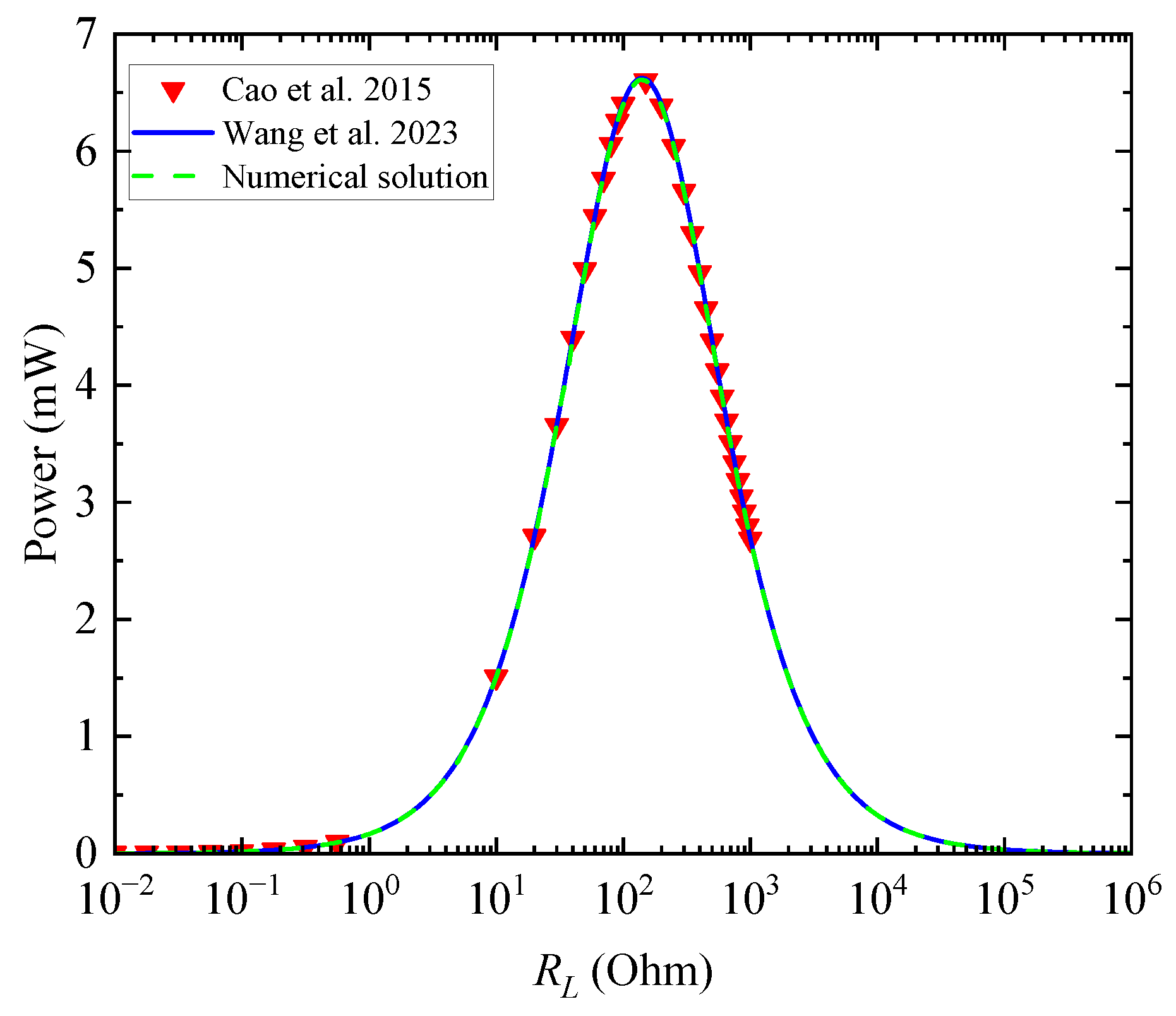
4.1. Model Validation

To assess the reliability of the proposed model, a degenerated cantilever Galfenol harvesting system is adopted by omitting the geometric nonlinearity characteristics of the cantilever structure and the NES coupling system for the proposed NES-Galfenol coupling system. The harvested power of the degenerated cantilever Galfenol harvesting system proposed in this paper is compared with those of the previous research [15,65], as shown as plotted in Figure 2. Note that the same physical and geometric parameters are used to obtain the numerical results of the degenerated cantilever Galfenol harvesting system by the Runge-Kutta method. As plotted in Figure 2, the harvested power of the discussed cantilever Galfenol harvesting system obtained by the proposed method is in good agreement with the theoretical analysis results and numerical solutions in other works [15,65]. This means that the proposed model and the derived results are reliable and applicable.

4.2. Comparison between the Linear and Nonlinear Systems

In order to analyze the difference between linear and nonlinear systems, four cases are adopted and discussed in this section. The four cases are pure linear systems, nonlinear systems that only consider NES, nonlinear systems that only consider geometric large deformations, and dual nonlinear systems that consider both NES and geometric large deformations. Among them, the dual nonlinear system is the proposed NES-Galfenol coupling system in this work. It is obvious that the governing equations of the other three systems (apart from the proposed NES-Galfenol coupling system) can be easily obtained by eliminating the corresponding nonlinear terms from the proposed coupling model, as shown in Equations (22)–(24). Note that the physical and geometric properties of the four mentioned cases, as well as all the cases discussed in the following sections, are shown in Table 1.
Figure 3 illustrates the variations of the output performances for the four mentioned coupled systems with the excitation frequency ratio (the ratio of the excitation frequency to the natural frequency, β ), at R L = 10 Ohm and a 0 = 2.1 m/s2. As plotted in Figure 3, for the pure linear system, the tip displacement and the harvested power reach the maximum value, i.e., 33.63 mm and 10.15 mW, at an excitation frequency ratio of 1.002. At this time, the excitation frequency is exactly equal to the natural frequency of the coupled structure. For nonlinear systems that only consider large geometric deformations, the maximum tip displacement of 31.45 mm and harvested power of 8.71 mW are obtained when the external excitation frequency ratio is 0.961. In particular, a softening phenomenon occurs, i.e., the output performances show a jumping phenomenon when the excitation frequency ratio reaches 0.954. For the nonlinear systems that only consider NES, the maximum tip displacement and harvested power are respectively 20.17 mm and 3.49 mW, with the excitation frequency ratio equal to 0.974. For the dual nonlinear systems that consider both NES and geometric large deformations, the maximum value of output properties are achieved, respectively, at 20.84 mm and 3.62 mW, with the excitation frequency ratio equal to 0.954.
The conclusion can be drawn from Figure 3 that the NES can effectively reduce the tip displacement as well as the harvested power. Besides, the excitation frequency ratio corresponding to the maximum output response shifts significantly to the left for the four discussed cases. This means that, after considering geometric nonlinearity, the optimal external excitation frequency ratio for the maximum output responses decreases and will result in a jump phenomenon and a nonlinear softening phenomenon. Moreover, when considering both the NES and the large deformation, the output performances are effectively reduced, as is the optimal external excitation frequency ratio, which corresponds to the maximum output response. However, the jumping phenomenon disappeared since the relatively small vibration amplitude cannot excite the geometric deformation effect. In other words, for the coupled model that introduces the NES, a larger external excitation amplitude is required to excite the geometric nonlinearity properties of the cantilever structure for the energy harvesting system.

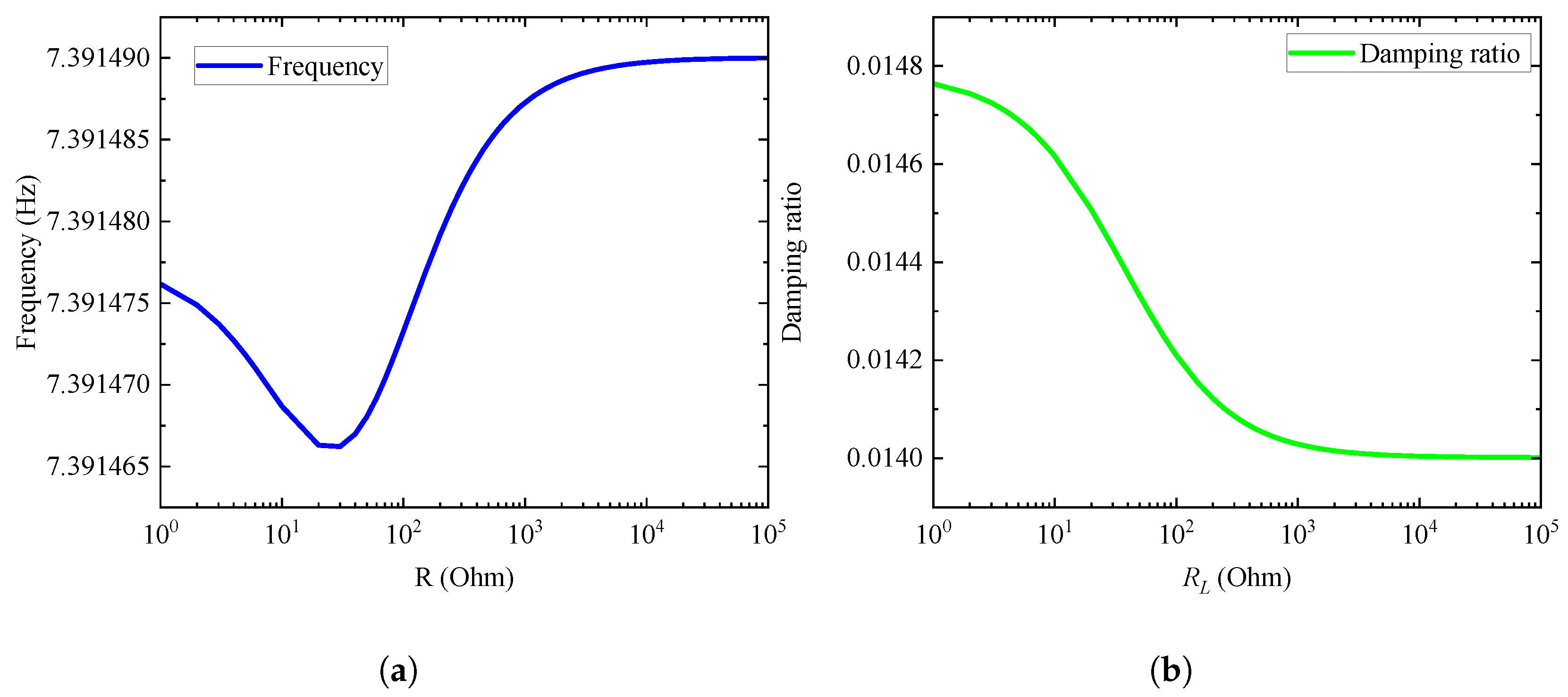
4.3. Effect of External Load Resistance on Global Damping and Frequency

The variation trends of the modified frequency and damping for the NES-Galfenol-coupled system considering dual nonlinearity with the external load resistance are presented in Figure 4. The modified frequency and global damping of the coupled system are gained by calculating the eigenvalue of the simplified matrix B as mentioned below Equation (32). As depicted in Figure 4, with the presence of electromechanical coupling for the Galfenol layer, the external load resistance will affect the global frequency and damping. Specifically, when the external resistance increases, the modified frequency first decreases, then increases, and finally stabilizes. The minimum value of the global frequency is reached at 30 Ohm. In contrast, the global damping of the proposed coupling system decreases with the increase in external load resistance. In general, the influence on the global frequency and damping of the coupled system is not obvious, which is inconsistent with the effect of resistance on piezoelectric energy harvesters considering geometric nonlinearity as illustrated in the previous work [51].

4.4. Parametric Analysis

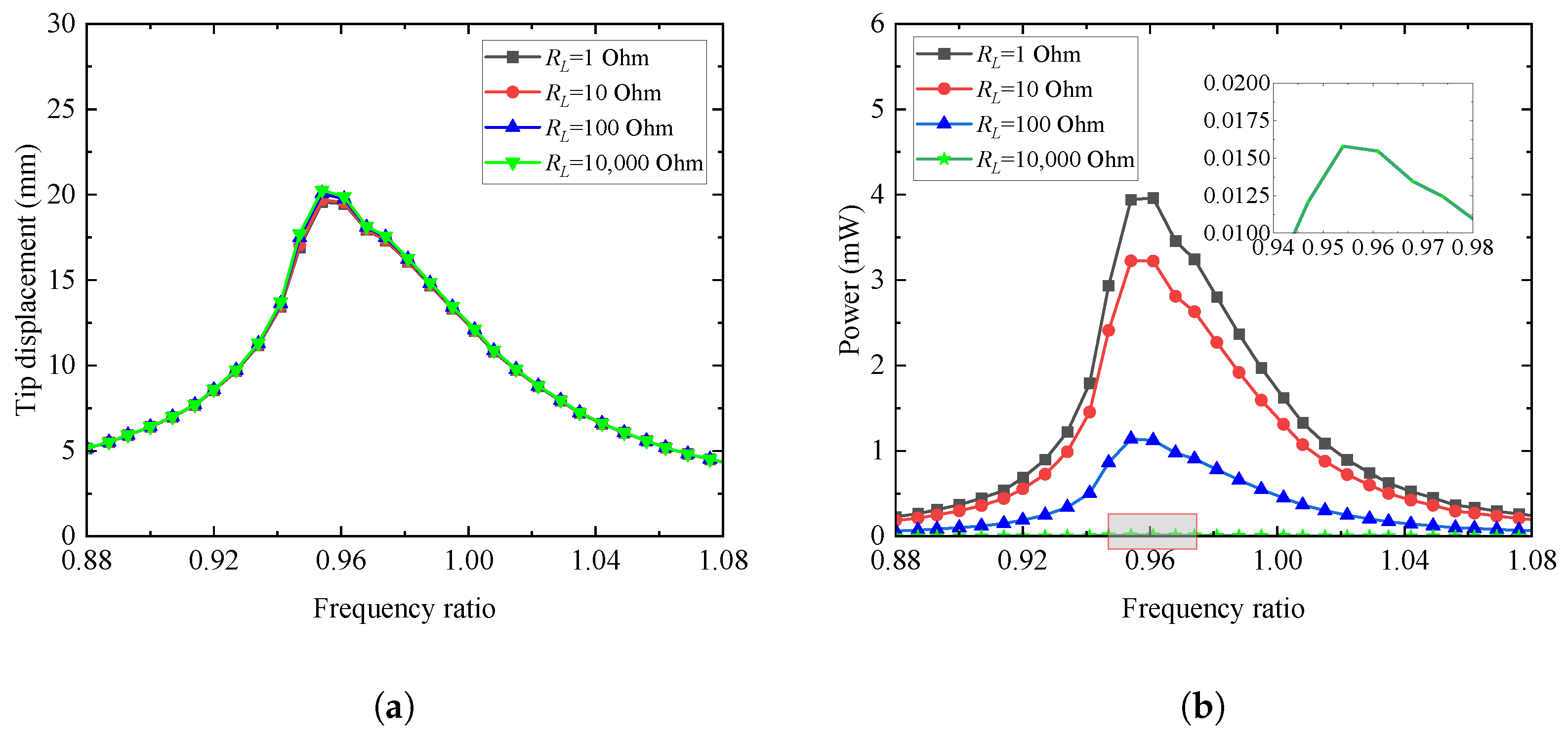
4.4.1. Effects of External Resistance and Excitation Frequency Ratio

Figure 5 presents the relationships of tip displacement and harvested power with the excitation frequency ratio for different external resistances at a 0 = 2 m/s2, k 2 = 10 5 N/m3, and c 2 = 0.4 N·s/m. Inspecting Figure 5, we note that with the increase of the external excitation frequency ratio, the tip displacement and output power of the coupled system increase with the excitation frequency ratio less than 0.961. Then the output performances decrease when the excitation frequency ratio exceeds 0.961. Moreover, as the external resistance rises, the harvested power gradually decreases while the tip displacement at the end of the cantilever structure is slightly increased. This can be explained by the fact that with the increase in resistance, the electrical damping of the coupled system faintly reduced, as illustrated in Figure 4. Additionally, inspecting Figure 4, the output results of the proposed NES-Galfenol coupling system show a certain left-bending trend, which is known as the nonlinear softening characteristics. As a comparison, the responding output results for the linear coupled system are symmetrical at an excitation frequency ratio of around 1.0, as presented in our previous work [15]. In general, external resistance has a relatively small impact on vibration displacement and a greater influence on harvested power. There always exists an optimal excitation frequency ratio corresponding to the maximum output performance. The nonlinear softening characteristics appeared with the introduction of geometric nonlinearity in cantilever structures.

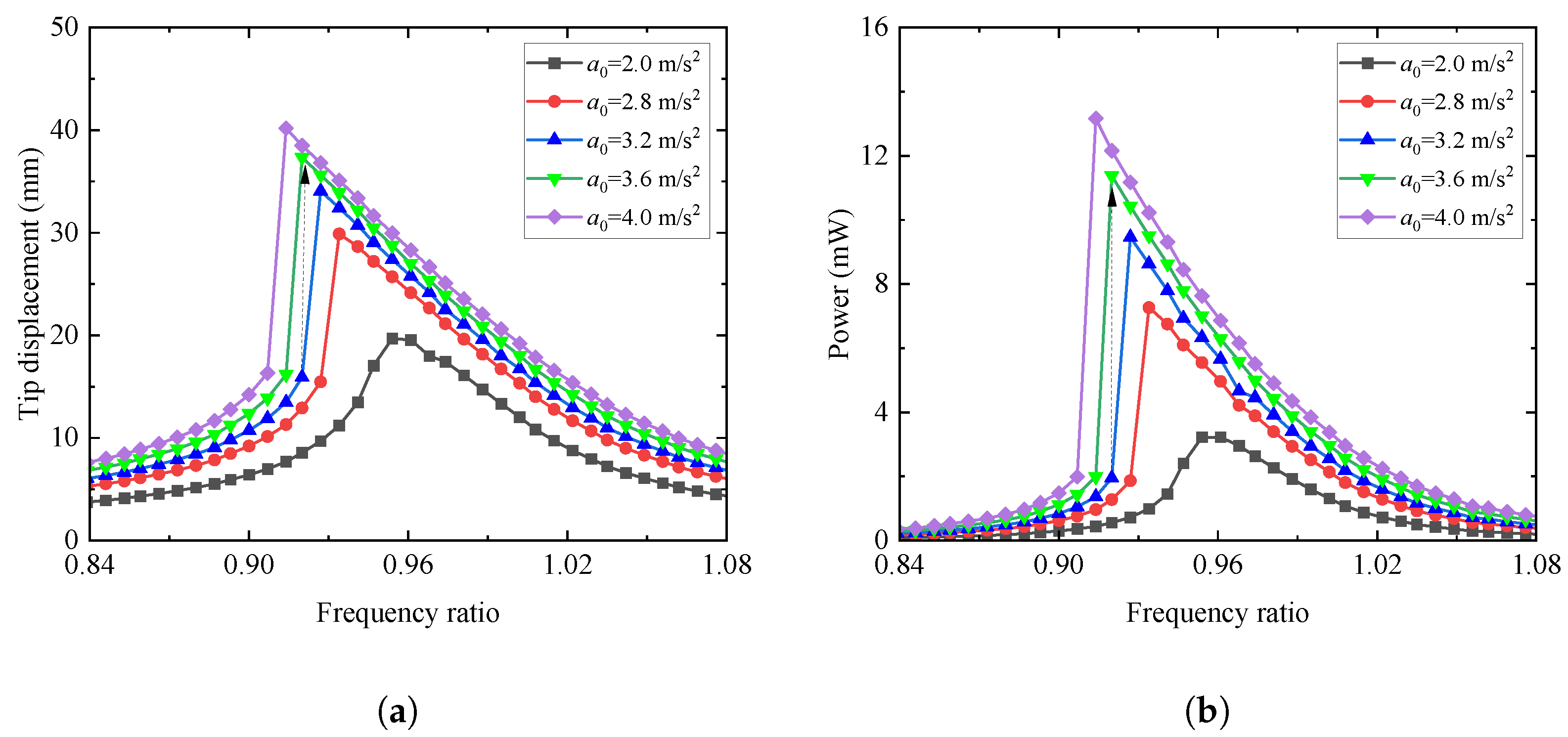
4.4.2. Effects of Excitation Acceleration Amplitude and Excitation Frequency Ratio

The influences of the excitation frequency ratio and the excitation acceleration on the output performances are plotted in Figure 6 for the case of R L = 10 Ohm, k 2 = 10 5 N/m3, and c 2 = 0.4 N·s/m. Inspecting Figure 6, as the excitation frequency ratio increases, the tip displacement and harvested power both first increase and then reduce to zero. Besides, with the increase in excitation acceleration, the vibration placement as well as the output power increase sequentially. It is noted that when the amplitude of the excitation acceleration reaches 2.8 m/s2, the output performances present a drastic change, as indicated by the black dashed arrow in the figure. This means that the jumping phenomenon occurs, i.e., the vibration characteristics of the coupled system jump from a stable motion with a smaller amplitude to another stable motion with a larger amplitude. This jumping phenomenon does not occur in the linear Galfenol energy harvesting coupled systems, as reported in the work [15]. In general, the plots show that when the amplitude of external excitation exceeds a certain value, a softening jump phenomenon of the output response will occur. The reason for this is that the geometric nonlinearity of the coupled system will be excited by increasing the excitation acceleration amplitude. As a result, when the softening phenomenon occurs, the output results show a clear left-bending trend. At this point, the working frequency range of the coupled system dramatically shifts to the left and widens, which is the output effect that this model aims to achieve.

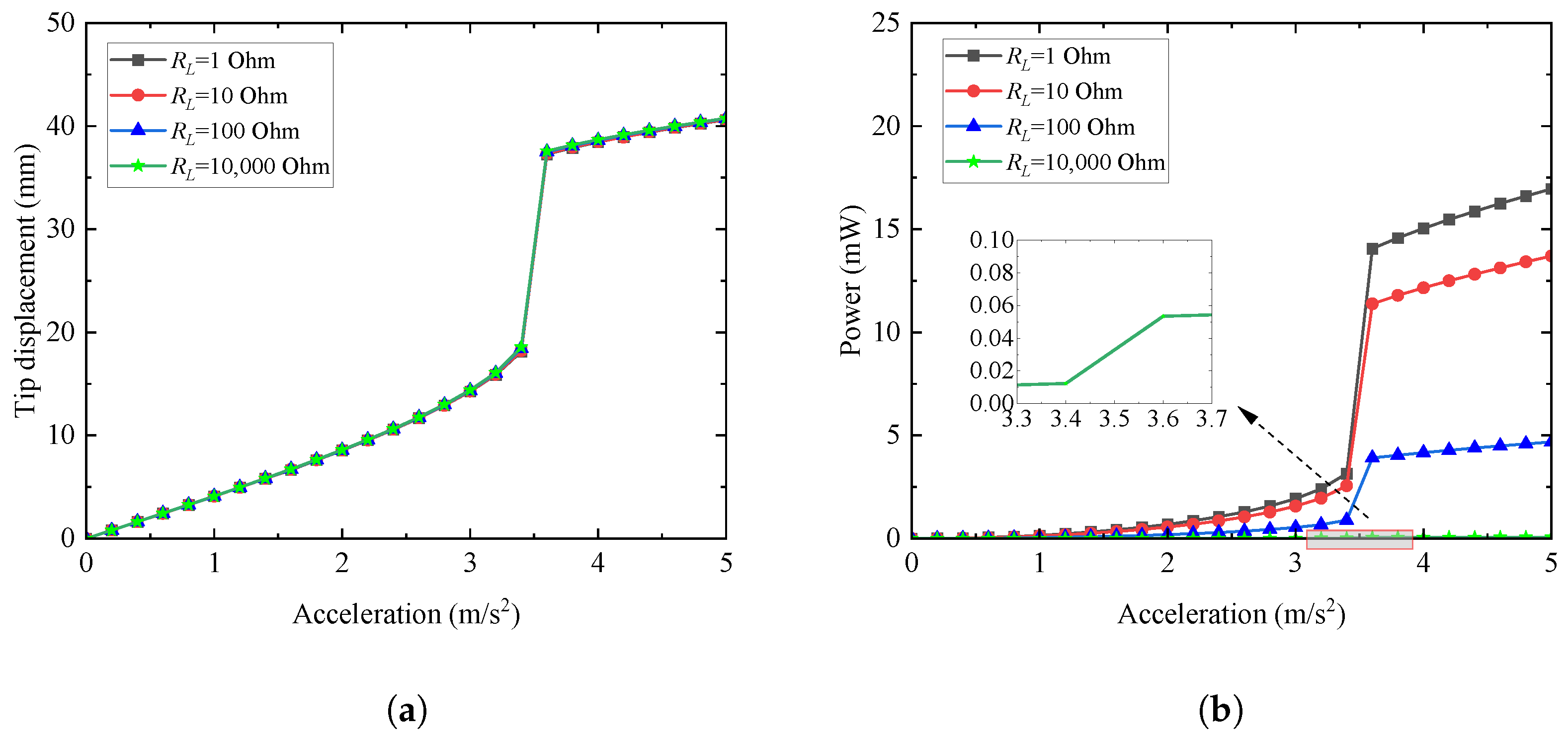
4.4.3. Effects of External Resistance and Excitation Acceleration Amplitude

Figure 7 illustrates the variations of the output performances with the amplitudes of the excitation acceleration for different external load resistances when the excitation frequency ratio is fixed at 0.920, k 2 = 10 5 N/m3, and c 2 = 0.4 N·s/m. As shown in Figure 7, the output performances of the coupled system first increase with the increase of the excitation acceleration amplitude. When the amplitude of the excitation acceleration reaches about 3.4 m/s, the vibration of the coupled system will jump to the upper branch. This branch corresponds to the output performance being stable in a periodic motion with a larger amplitude. It means that the jumping phenomenon occurs when the excitation acceleration exceeds a certain value. In addition, as depicted in Figure 7, the harvested power of the coupled system declines with the external load resistance increasing from 1 Ohm to 10 Ohm, 10 2 Ohm, and 10 4 Ohm. At this time, as the resistance of the external circuit changes, the vibration displacement remains unchanged. This indicates that the value of the external resistance has little effect on the vibration displacement and has a reverse effect on the harvested power. As a consequence, to obtain a larger output power, the resistance of the external circuit and the excitation acceleration should be taken as smaller and larger values, respectively.
Figure 8 shows the changes of the tip displacement and harvested power for the coupled system with the excitation acceleration amplitude when the external load resistance is respectively set as 1, 10, 10 2 , and 10 4 Ohm and the excitation frequency ratio is equal to 0.988, k 2 = 10 5 N/m3, and c 2 = 0.4 N·s/m. As presented in Figure 8, the output performances of the coupled system gradually increase with the increase of the excitation acceleration. As the external load resistance increases, the harvested power decreases significantly. The effect of the external resistance on the tip displacement of the coupled system can be almost negligible. Compared to the responses in Figure 7, the output responses of the coupled system still increase with the increase in excitation acceleration, but no nonlinear jumping phenomenon occurs. This can be explained by the reason that with the excitation frequency ratio closer to 1, the output result is farther away from the left-bending region (the softening region) plotted in Figure 5 and Figure 6. Therefore, it can be concluded that the nonlinear jumping phenomenon will not be induced with the excitation frequency ratio far away from the softening region.

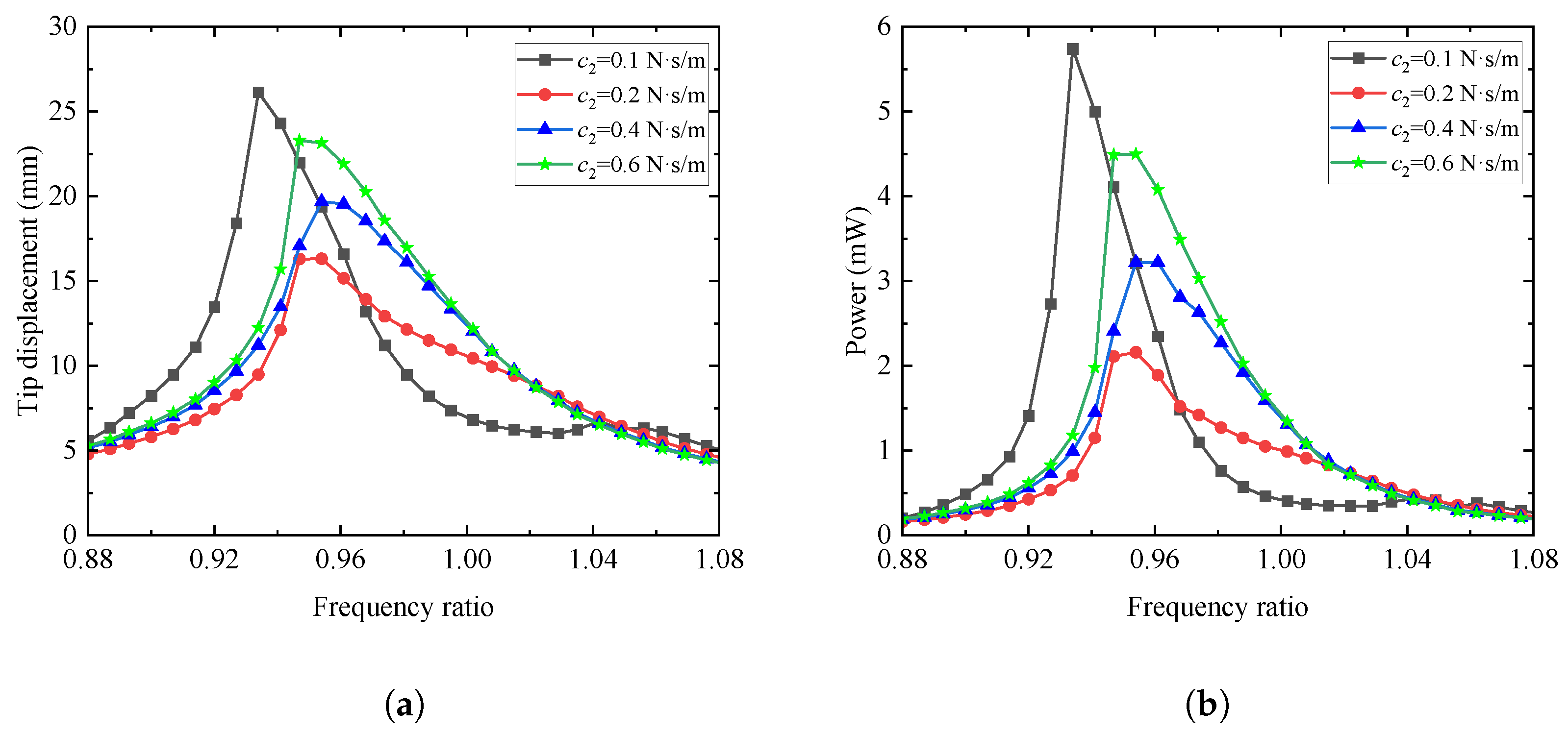
4.4.4. Effects of the Damping and Nonlinear Stiffness for the NES

Figure 9 presents the variations of the output performances with the damping of the NES for the cases of R L = 10 Ohm, a 0 = 2 m/s2, and k 2 = 10 5 N/m3. As illustrated in Figure 9, the output responses of the coupled system first increase as the excitation frequency ratio approaches the optimal frequency ratio, then decrease as the excitation frequency ratio gradually shifts away from the optimal frequency ratio. In addition, as the damping increases from 0.1 N·s/m to 0.6 N·s/m, the vibration displacement and harvested power first decrease and then increase. With the increase in the NES damping, the optimal excitation frequency ratio corresponding to the maximum output response increases first and then declines. Moreover, the softening phenomenon of the output responses shows a trend of first weakening and then strengthening as the NES damping increases. This means that the damping of NES should be taken as a smaller or larger value to achieve better output performance for a wider excitation frequency range.
The varied relationships of the tip displacement and harvested power with the excitation frequency ratio for different NES stiffnesses are depicted in Figure 10 for the case of R L = 10 Ohm, a 0 = 2 m/s2, and c 2 = 0.4 N·s/m. Inspecting Figure 10, it is obvious that the changing trend of the output properties to the excitation frequency ratio is consistent with those in Figure 9. That is, the output responses increase first and then decrease with the growth of the excitation frequency ratio. As the NES stiffness rises from 10 4 N/m3 to 10 7 N/m3, the tip displacement and harvested power first decline and then increase sequentially. Additionally, the softening phenomenon of output responses is gradually emerging and becomes apparent with the growth of the NES stiffness. The optimal excitation frequency ratio corresponding to the maximum output performance shows a trend of left shift as the NES stiffness increases. Therefore, in order to harvest more energy within a wider range of excitation frequencies, the stiffness of NES should be taken as high as possible.

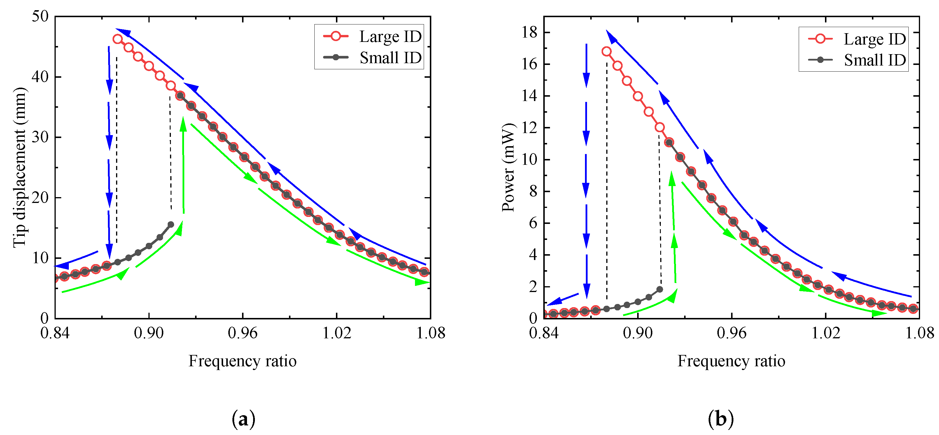
4.4.5. Effects of the Initial Excitation Condition

To clarify the influences of the initial excitation condition on the output responses of the proposed NES-Galfenol coupling system, the excitation acceleration amplitude, the external resistance, the NES damping, and the NES stiffness are respectively set as a 0 = 3.5 m/s2, R L = 10 Ohm, c 2 = 0.4 N·s/m, and k 2 = 10 5 N/m3. Two initial excitation conditions, i.e., the small and large initial excitation displacements, are selected for analysis. The tip displacement and harvested power of the coupled system with the mentioned two initial excitation conditions are presented in Figure 11. It is noted that the symbol ID in the figure represents the initial displacement of the discussed coupling system. The green and blue arrows represent the direction of the forward or reverse sweep frequency, respectively.
As observed in Figure 11, the changing curves of the vibration displacement and harvested power both exhibit jumping phenomena with the change of the excitation frequency ratio. In the case of forward sweep frequency analysis with a small initial displacement, the response of the coupled system increases gradually when the excitation frequency ratio is less than 0.920. Then it jumps from the lower branch to the upper branch while the excitation frequency ratio reaches 0.920, and finally gradually decreases when the excitation frequency ratio is larger than 0.920. In the case of reverse sweep frequency analysis with the large initial displacement, as the excitation frequency ratio decreases, the response of the coupled system grows gradually until the excitation frequency ratio is greater than 0.873. Then it decreases gradually for the excitation frequency ratio less than 0.873. When the excitation frequency ratio is equal to 0.873, the output performance jumps from the upper branch to the lower branch. This indicates that 0.920 and 0.873 are, respectively, the jumping thresholds of the output responses for the small initial condition and the large initial condition. Comparing the output performances of the two discussed cases, the output responses for the large ID are dramatically greater than those for the small ID when the excitation frequency ratio is in the jumping range. The jumping range can be called the softening region for the output responses. In this region, two steady-state solutions of the output performances for the coupled system can be obtained. Consequently, the wider the range of jump intervals, the better the output performance of the proposed NES-Galfenol coupling system.
To further clarify the effect of initial conditions on the output responses, the time history curve and phase portrait curve for the tip displacement are illustrated in Figure 12. The results plotted in Figure 12 are obtained by the external excitation frequency ratio, which is respectively set at 0.920 and 0.988. As can be seen from Figure 11, the two adopted excitation frequency ratios are respectively located in and outside the jumping region. Inspecting Figure 12a,c, we found that with the excitation frequency ratio inside the jumping region, there are indeed two steady-state solutions for the vibration responses. For the case of the excitation frequency ratio equal to 0.988, Figure 12b,d show that the steady-state vibration responses for the different initial conditions are in good agreement. It means that the initial conditions no longer affect the vibration response when the excitation frequency ratio is outside the jumping range. In general, when the excitation frequency ratio is located in the jumping range, two stable vibration responses will be found for various initial conditions. When the excitation frequency is beyond the jumping region, only one stable vibration response can be observed for different initial conditions.

5. Conclusions

In recent years, Galfenol, a novel magnetostrictive material, has increasingly been utilized in the field of vibration energy harvesting. NES, commonly used for vibration reduction, has garnered interest from researchers in energy harvesting because of its simple structure, wide working frequency band, and high robustness. Inspecting the previous works, researchers mainly devote themselves to introducing the NES or geometric nonlinearity into piezoelectric energy harvesting systems to obtain better output performances. This work proposes the NES-Galfenol coupling system by combining the advantages of NES and Galfenol materials. The proposed model can achieve the multifunctional goal of suppressing the vibration of the main structure and protecting the safety of the cantilever energy harvesting system while capturing energy. Based on the inverse magnetostrictive effect, Faraday electromagnetic induction effect of Galfenol material, and Hamilton variational principle, the electromechanically coupled distributed parameter governing equations of the proposed coupling system are formulated. It is noted that the geometric nonlinear characteristics of cantilever beams and stiffness nonlinear characteristics of NES are considered in the deriving process. According to the Galerkin discretization method, the reduced-order equations are deduced. The numerical solutions of the proposed NES-Galfenol coupling system are calculated by the Runge-Kutta method. A comparative analysis was conducted on the effects of geometric nonlinearity and NES on the output performances of the cantilever Galfenol energy harvesting system. Moreover, the influences of the excitation acceleration amplitude, excitation frequency ratio, external load resistance, NES damping and stiffness, and the initial excitation condition on the output performances of the proposed coupling system are conducted. The main conclusions drawn from this work are as follows:
(1)
The numerical calculation solutions of the proposed coupling system reveal that the addition of an NES can effectively reduce the vibration behaviors of the cantilever Galfenol energy harvesting system. After considering the geometric nonlinearity of the cantilever beam, the jumping phenomenon will occur relative to the linear system.
(2)
For any fixed external load resistance, excitation acceleration amplitude, NES damping, or NES nonlinear stiffness, the corresponding optimal range of the excitation frequency ratio, around 0.96, could be identified to maximize the harvested power.
(3)
When the external excitation acceleration, NES damping, and nonlinear stiffness exceed a certain threshold, the system output responses will exhibit a jumping phenomenon, namely the nonlinear softening phenomenon. In the nonlinear softening range, two branching curves exist, corresponding to the responses of small and large initial conditions, respectively. In the non-softening range, there is only one branching curve. This means that the output response of the coupled system is independent of the initial conditions when the excitation is outside the jumping region.
(4)
In summary, to achieve better energy harvesting characteristics, the external resistance should be taken as small (such as R L < 10 Oom) and the external excitation amplitude should be larger (such as a 0 > 2.8 m/s2). The NES damping should be taken as a smaller or larger value (such as c 2 = 0.1 N· s/m or c 2 > 0.4 N· s/m), and the stiffness of the NES should be as large as possible (such as k 2 > 106 N/m3). Then the appearance of the nonlinear softening phenomenon will occur and effectively expand the vibration energy-capturing frequency bandwidth of the proposed coupling system.
In addition, it is particularly pointed out that the correct selection of calculation methods will significantly affect the computational efficiency and accuracy of the coupled model. Zhang et al. [66] proposed a novel stochastic homotopy method to discuss the structure-static features with random variables distributed arbitrarily. It is concluded that this proposed new method has excellent accuracy and stability. In this work, through the numerical parameter analysis, the intrinsical characteristics of the influence of some parameters on the output response of the coupled system can be preliminarily obtained. However, the specific optimal parameter values cannot be directly determined to achieve the best harvesting performance. Excitedly, with the development of computer technology and big data technology, the optimization analysis can be effectively trained through machine learning-based and artificial neural network-based algorithms (DL and ANN) [67,68]. This means that in view of the DL and ANN method, the specified optimal parameters of coupled system can be confirmed by effectively training after the dynamic governing equation of the NES-Galfenol coupled system is determined. This will greatly improve the optimization analysis efficiency of the dual nonlinear coupling model proposed in this work, which will be the research direction of our team in the future. Similarly, the DL and ANN methods can provide technical support for parameter optimization analysis of nonlinear dynamic systems in other fields. Therefore, the DL and ANN methods deserve more attention and discussion for parameter optimization analysis in the future.

Author Contributions

Author Contributions: Conceptualization, L.W.; Methodology, C.L.; Software, C.L. and L.W.; Validation, C.L.; Investigation, C.L.; Data curation, C.L. and W.L.; Writing—original draft, C.L.; Writing—review & editing, C.L. and L.W.; Visualization, Z.Y. and X.N.; Supervision, Z.Y. and X.N. All authors have read and agreed to the published version of the manuscript.

Funding

This study is supported by the National Natural Science Foundation of China (Grant No.: 52178458), Natural Science Foundation of Chongqing Science and Technology Commission (Grant No.: CSTB2022NSCQ-MSX0469), Science and Technology Research Project of Chongqing Education Commission (Grant No.: KJQN202101521), Research Project of Chongqing Doctoral “Through Train” of China (Grant No.: CSTB2022BSXM-JCX0164), Research support project of Chongqing University of Science and Technology (Grant No.:ckrc2020011), China Postdoctoral Science Foundation (Grant No.: 2022M720021), Chongqing Natural Science Foundation General Project (CSTB2022NSCQ-MSX0518), Chongqing Technological Innovation and Application Development Project (CSTB2022TIAD-KPX0144), Chongqing Construction Science and Technology Plan Project: Chengkezi 2023 No.1-1, and Natural Science Foundation of Chongqing of China (No.: CSTB2023NSCQ-LZX0051).

Data Availability Statement

The original contributions presented in the study are included in the article, further inquiries can be directed to the corresponding author.

Conflicts of Interest

The authors declare that they have no known competing financial interests or personal relationships that could have appeared to influence the work.

References

  1. Alavi, A.H.; Hasni, H.; Lajnef, N.; Chatti, K.; Faridazar, F. An intelligent structural damage detection approach based on self powered wireless sensor data. Automat. Constr. 2016, 62, 24–44. [Google Scholar] [CrossRef]
  2. Clemente, C.S.; Mahgoub, A.; Davino, D.; Visone, C. Multiphysics circuit of a magnetostrictive energy harvesting device. J. Intel. Mat. Syst. Str. 2017, 28, 2317–2330. [Google Scholar] [CrossRef]
  3. Wang, L.Z.; Tan, T.; Yan, Z.M.; Yan, Z.T. Tapered galloping energy harvester for power enhancement and vibration reduction. J. Intel. Mat. Syst. Str. 2019, 30, 2853–2869. [Google Scholar] [CrossRef]
  4. Dragunov, V.P.; Ostertak, D.I.; Sinitskiy, R.E. New modifications of a Bennet doubler circuit-based electrostatic vibrational energy harvester. Sens. Actuat. A-Phys. 2020, 302, 111812. [Google Scholar] [CrossRef]
  5. Tan, Y.; Dong, Y.; Wang, X. Review of MEMS Electromagnetic Vibration Energy Harvester. J. Microelectromech. Syst. 2017, 26, 1–16. [Google Scholar] [CrossRef]
  6. Budhathoki, S.; Sapkota, A.; Law, K.M.; Nepal, B.; Ranjit, S.; Kc, S.; Mewes, T.; Hauser, A.J. Low Gilbert damping and linewidth in magnetostrictive FeGa thin films. J. Magn. Magn. Mater. 2020, 496, 165906. [Google Scholar] [CrossRef]
  7. Moradian, K.; Sheikholeslami, T.F.; Raghebi, M. Investigation of a spherical pendulum electromagnetic generator for harvesting energy from environmental vibrations and optimization using response surface methodology. Energ. Convers. Manag. 2022, 266, 115825. [Google Scholar] [CrossRef]
  8. Jin, Y.; Xiao, S.; Zhang, Y. Enhancement of tristable energy harvesting using stochastic resonance. J. Stat. Mech. Theory Exp. 2018, 23, 123–211. [Google Scholar] [CrossRef]
  9. Yang, T.; Cao, Q. Novel multi-stable energy harvester by exploring the benefits of geometric nonlinearity. J. Stat. Mech. Theory Exp. 2019, 7, 033405. [Google Scholar] [CrossRef]
  10. Wang, W.; Cao, J.; Wei, Z.H.; Litak, G. Approximate Fokker-Planck-Kolmo-gorovequation analysis for asymmetric multistable energy harvesters excited by white noise. J. Stat. Mech. Theory Exp. 2021, 3, 023407. [Google Scholar] [CrossRef]
  11. Chand, R.R.; Tyagi, A. Investigation of the Effects of the Piezoelectric Patch Thickness and Tapering on the Nonlinearity of a Parabolic Converging Width Vibration Energy Harvester. J. Vib. Eng. Technol. 2021, 10, 1–18. [Google Scholar] [CrossRef]
  12. Ghouli, Z.; Litak, Z. Effect of High-Frequency Excitation on a Bistable Energy Harvesting System. J. Vib. Eng. Technol. 2023, 11, 99–106. [Google Scholar] [CrossRef]
  13. Lin, C.H.; Lin, Y.Z. Analysis of nonlinear piezomagnetism for magnetostrictive terfenol-D composites. J. Magn. Magn. Mater. 2021, 540, 168490. [Google Scholar] [CrossRef]
  14. Nakajima, K.; Tanaka, S.; Mori, K.; Kurita, H.; Narita, F. Effects of Heat Treatment and Cr Content on the Microstructures, Magnetostriction, and Energy Harvesting Performance of Cr-Doped-Fe-Co Alloys. Adv. Eng. Mater. 2021, 24, 2101036. [Google Scholar] [CrossRef]
  15. Wang, L.Z.; Lian, C.L.; Shu, D.L.; Yan, Z.T.; Nie, X.C. Analytical solution and optimal design for the output performance of Galfenol cantilever energy harvester considering electromechanical coupling effect. Sci. Rep. 2023, 13, 12857. [Google Scholar] [CrossRef] [PubMed]
  16. Yang, Z.; Tan, Y.; Zu, J. A multi-impact frequency up-converted magnetostrictive transducer for harvesting energy from finger tapping. Int. J. Mech. Sci. 2017, 126, 235–241. [Google Scholar] [CrossRef]
  17. Wu, J.; Hu, Z.; Gao, X.; Cheng, M.; Zhao, X.; Su, W.; Li, X.; Wang, Z.; Zhou, Z.; Dong, S.; et al. Electrode shape dependence of the barbell-shaped magneto-mechano-electric energy harvester for low-frequency applications. Sens. Actuat. A-Phys. 2019, 297, 111535. [Google Scholar] [CrossRef]
  18. Yoo, J.H.; Flatau, A.B. A bending-mode galfenol electric power harvester. J. Intell. Mater. Syst. Struct. 2012, 23, 647–654. [Google Scholar] [CrossRef]
  19. Atulasimha, J.; Flatau, A.B. A review of magnetostrictive iron-gallium alloys. Smart. Mater. Struct. 2011, 20, 043001. [Google Scholar] [CrossRef]
  20. Davino, D.; Giustiniani, A.; Visone, C.; Adly, A.A. Energy Harvesting Tests With Galfenol at Variable Magneto-Mechanical Conditions. IEEE Trans. Magn. 2012, 48, 3096–3309. [Google Scholar] [CrossRef]
  21. Clark, A.E.; Hathaway, K.B.; Wun-Fogle, M.; Restorff, J.B.; Lograsso, T.A.; Keppens, V.M.; Petculescu, G.; Taylor, R.A. Extraordinary magnetoelasticity and lattice softening in bcc Fe-Ga alloys. J. Appl. Phys. 2003, 93, 8621–8623. [Google Scholar] [CrossRef]
  22. Javed, A.; Morley, N.A.; Gibbs, M.R.J. Structure, magnetic and magnetostrictive properties of as-deposited Fe-Ga thin films. J. Magn. Magn. Mater. 2009, 321, 2877–2882. [Google Scholar] [CrossRef]
  23. Cao, S.; Zheng, J.; Guo, Y.; Li, Q.; Sang, J.; Wang, B.; Yan, R. Dynamic Characteristics of Galfenol Cantilever Energy Harvester. IEEE Trans. Magn. 2015, 51, 1–4. [Google Scholar] [CrossRef]
  24. Cao, S.Y.; Sun, S.S.; Zheng, J.J.; Wang, B.; Wan, L.L.; Pan, R.Z.; Zhao, R.; Zhang, C.G. Modeling and analysis of Galfenol cantilever vibration energy harvester with nonlinear magnetic force. AIP Adv. 2018, 8, 056718. [Google Scholar] [CrossRef]
  25. Clemente, C.S.; Davino, D.; Loschiavo, V.P. Analysis of a Magnetostrictive Harvester With a Fully Coupled Nonlinear FEM Modeling. IEEE Trans. Magn. 2021, 57, 4001201. [Google Scholar] [CrossRef]
  26. Jin, S.; Meng, A.; Li, M.; Xu, Z.; Wu, S.; Chen, Y. Modeling and Analysis of Wave Energy Harvester with Symmetrically Distributed Galfenol Cantilever Beams. Materials 2023, 16, 5585. [Google Scholar] [CrossRef] [PubMed]
  27. Vakakis, A.F.; Manevitch, L.I.; Gendelman, O.; Bergman, L. Dynamics of linear discrete systems connected to local essentially nonlinear attachments. J. Sound. Vib. 2003, 264, 559–577. [Google Scholar] [CrossRef]
  28. Panagopoulos, P.N.; Vakakis, A.F.; Tsakirtzis, S. Transient resonant interactions of linear chains with essentially nonlinear end attachments leading to passive energy pumping. Int. J. Solids. Struct. 2004, 41, 6505–6528. [Google Scholar] [CrossRef]
  29. Vakakis, A.F. Inducing passive nonlinear energy sinks in vibrating systems. J. Vib. Acoust. 2001, 123, 324–332. [Google Scholar] [CrossRef]
  30. Gendelman, O.V.; Manevitch, L.I.; Vakakis, A.F.; Closkey, R.M. Energy pumping in nonlinear mechanical oscillators: Part I-Dynamics of the underlying Hamiltonian systems. J. Appl. Mech. 2001, 68, 34–41. [Google Scholar] [CrossRef]
  31. Georgiades, F.; Vakakis, A.F. Dynamics of a linear beam with an attached local nonlinear energy sink. Commun. Nonlinear. Sci. 2007, 12, 643–651. [Google Scholar] [CrossRef]
  32. Gendelman, O.V.; Sapsis, T.; Vakakis, A.F.; Bergman, L.A. Enhanced passive targeted energy transfer in strongly nonlinear mechanical oscillators. J. Sound. Vib. 2011, 330, 1–8. [Google Scholar] [CrossRef]
  33. Kani, M.; Khadem, S.E.; Pashaei, M.H.; Dardel, M. Vibration control of a nonlinear beam with a nonlinear energy sink. Nonlinear Dynam. 2016, 83, 1–22. [Google Scholar] [CrossRef]
  34. Parseh, M.; Dardel, M.; Ghasemi, M.H.; Pashaei, M.H. Steady state dynamics of a non-linear beam coupled to a non-linear energy sink. Int. J. Nonlin. Mech. 2016, 79, 48–65. [Google Scholar] [CrossRef]
  35. Ahmadabadi, Z.N.; Khadem, S.E. Nonlinear vibration control and energy harvesting of a beam using a nonlinear energy sink and a piezoelectric device. J. Sound. Vib. 2014, 333, 4444–4457. [Google Scholar] [CrossRef]
  36. Kremer, D.; Liu, K. A nonlinear energy sink with an energy harvester: Transient responses. J. Sound. Vib. 2014, 333, 4859–4880. [Google Scholar] [CrossRef]
  37. Kremer, D.; Liu, K. A nonlinear energy sink with an energy harvester: Harmonically forced responses. J. Sound. Vib. 2017, 410, 287–302. [Google Scholar] [CrossRef]
  38. Xiong, L.; Tang, L.; Liu, K.; Mace, B.R. Broadband piezoelectric vibration energy harvesting using a nonlinear energy sink. J. Phys. D Appl. Phys. 2018, 51, 185502. [Google Scholar] [CrossRef]
  39. Tian, W.; Li, Y.M.; Yang, Z.C.; Li, P.; Zhao, T. Suppression of nonlinear aeroelastic responses for a cantilevered trapezoidal plate in hypersonic airflow using an energy harvester enhanced nonlinear energy sink. Int. J. Mech. Sci. 2020, 172, 105417. [Google Scholar] [CrossRef]
  40. Fang, Z.W.; Zhang, Y.W.; Li, X.; Ding, H.; Chen, L.Q. Integration of a nonlinear energy sink and a giant magnetostrictive energy harvester. J. Sound. Vib. 2017, 391, 35–49. [Google Scholar] [CrossRef]
  41. Wang, Z.J.; Zang, J.; Zhang, Y.W. Method for Controlling Vibration and Harvesting Energy by Spacecraft: Theory and Experiment. AIAA J. 2022, 60, 6097–6115. [Google Scholar] [CrossRef]
  42. Xu, K.F.; Zhang, Y.W.; Niu, M.Q.; Zang, J.; Xue, J.; Chen, L.Q. An improved nonlinear energy sink with electromagnetic damping and energy harvesting. Int. J. Appl. Mech. 2022, 14, 2250055. [Google Scholar] [CrossRef]
  43. Zhang, Y.W.; Gao, C.Q.; Zhang, Z.; Zang, J. Dynamic Analysis of Vibration Reduction and Energy Harvesting Using a Composite Cantilever Beam with Galfenol and a Nonlinear Energy Sink. Int. J. Mech. Sci. 2021, 13, 2150089. [Google Scholar] [CrossRef]
  44. Xue, J.R.; Zhang, Y.W.; Niu, M.Q.; Chen, L.Q. Harvesting electricity from random vibrations via a nonlinear energy sink. J. Vib. Control 2023, 29, 5398–5412. [Google Scholar] [CrossRef]
  45. Xu, K.F.; Zhang, Y.W.; Zang, J.; Niu, M.Q.; Chen, L.Q. Integration of vibration control and energy harvesting for whole-spacecraft: Experiments and theory. Mech. Syst. Signal. Process. 2021, 161, 107956. [Google Scholar] [CrossRef]
  46. Zhang, Y.W.; Su, C.; Ni, Z.Y.; Zang, J.; Chen, L.Q. A multifunctional lattice sandwich structure with energy harvesting and nonlinear vibration control. Compos. Struct. 2019, 221, 110875. [Google Scholar] [CrossRef]
  47. Li, J.; He, X.; Yang, X.; Liu, Y. A consistent geometrically nonlinear model of cantilevered piezoelectric vibration energy harvesters. J. Sound. Vib. 2020, 486, 115614. [Google Scholar] [CrossRef]
  48. Tan, T.; Yan, Z.M.; Lei, H.; Sun, W.P. Geometric nonlinear distributed parameter model for cantilever beam piezoelectric energy harvesters and structural dimension analysis for galloping mode. J. Intell. Mater. Syst. Struct. 2017, 28, 3066–3078. [Google Scholar] [CrossRef]
  49. Shooshtari, A.; Hoseini, S.M.; Mahmoodi, S.N.; Kalhori, H. Analytical solution for nonlinear free vibrations of viscoelastic microcantilevers covered with a piezoelectric layer. Smart. Mater. Struct. 2012, 21, 075015. [Google Scholar] [CrossRef]
  50. Li, H.S.; Sun, H.X.; Song, B.Y.; Zhang, D.; Shang, X.C.; Liu, D.H. Nonlinear dynamic response of an L-shaped beam-mass piezoelectric energy harvester. J. Sound. Vib. 2021, 499, 116004. [Google Scholar] [CrossRef]
  51. Nie, X.C.; Tan, T.; Yan, Z.M.; Yan, Z.T.; Hajj, M.R. Broadband and high-efficient L-shaped piezoelectric energy harvester based on internal resonance. Int. J. Mech. Sci. 2019, 159, 287–305. [Google Scholar] [CrossRef]
  52. Nie, X.C.; Tan, T.; Yan, Z.M.; Yan, Z.T.; Zhang, W.M. Ultra-wideband piezoelectric energy harvester based on Stockbridge damper and its application in smart grid. Appl. Energ. 2020, 267, 114898. [Google Scholar] [CrossRef]
  53. Nie, X.C.; Gao, X.; Wang, L.Z.; Tan, T.; Yan, Z.T.; Yan, Z.M.; Liu, X. Nonlinear analysis of the internal resonance response of an L-shaped beam structure considering quadratic and cubic nonlinearity. J. Stat. Mech. Theory Exp. 2022, 2, 023204. [Google Scholar] [CrossRef]
  54. Nie, X.C.; Tan, T.; Yan, Z.M.; Yan, Z.T.; Wang, L.Z. Revised method of multiple scales for 1:2 internal resonance piezoelectric vibration energy harvester considering the coupled frequency. Commun. Nonlinear Sci. 2023, 118, 107018. [Google Scholar] [CrossRef]
  55. Han, Q.K.; Li, X.L.; Chu, F.L. Skidding behavior of cylindrical roller bearings under time-variable load conditions. Int. J. Mech. Sci. 2018, 135, 203–214. [Google Scholar] [CrossRef]
  56. Han, Q.K.; Chu, F.L. Nonlinear dynamic model for skidding behavior of angular contact ball bearings. J. Sound. Vib. 2015, 354, 219–235. [Google Scholar] [CrossRef]
  57. Wang, H.; Han, Q.K.; Zhou, D. Nonlinear dynamic modeling of rotor system supported by angular contact ball bearings. Mech. Syst. Signal. Process. 2017, 85, 16–40. [Google Scholar] [CrossRef]
  58. Liu, W.R.; Bai, X.; Yang, H.; Bao, R.X.; Liu, J.Q. Tendon driven bistable origami flexible gripper for high-speed adaptive grasping. IEEE Robot. Autom. Lett. 2024, 9, 5417–5424. [Google Scholar] [CrossRef]
  59. Clemente, C.; Davino, D. Modeling and characterization of a kinetic energy harvesting device based on galfenol. Materials 2019, 12, 3199. [Google Scholar] [CrossRef] [PubMed]
  60. Erturk, A.; Inman, D.J. Piezoelectric Energy Harvesting-Base Excitation Problem for Cantilevered Structures and Correction of the Lumped-Parameter Electromechanical Model; John Wiley and Sons: Hoboken, NJ, USA, 2011; pp. 19–48. [Google Scholar] [CrossRef]
  61. Erturk, A.; Inman, D. An experimentally validated bimorph cantilever model for piezoelectric energy harvesting from base excitations. Smart Mater. Struct. 2009, 18, 025009. [Google Scholar] [CrossRef]
  62. Erturk, A.; Hoffmann, J.; Inman, D.J. A piezomagnetoelastic structure for broadband vibration energy harvesting. Appl. Phys. Lett. 2009, 94, 254102. [Google Scholar] [CrossRef]
  63. Bibo, A.; Abdelkefi, A.; Daqaq, M.F. Modeling and characterization of a piezoelectric energy harvester under combined aerodynamic and base excitations. J. Vin. Acoust. 2015, 137, 031017. [Google Scholar] [CrossRef]
  64. Khazaee, M.; Rezaniakolaei, A.; Rosendahl, L. An experimental study to determine damping of piezoelectric harvesters using transient analysis of unified electromechanical voltage equation. Energ. Convers. Manag. 2021, 227, 113567. [Google Scholar] [CrossRef]
  65. Cao, S.; Sang, J.; Zheng, J.; Wang, B. Electromechanical coupling dynamic model of galfenol cantilever energy harvester. Proc. CSEE 2015, 35, 5623–5631. (In Chinese) [Google Scholar]
  66. Zhang, H.; Xiang, X.; Huang, B.; Wu, Z.F.; Chen, H. Static homotopy response analysis of structure with random variables of arbitrary distributions by minimizing stochastic residual error. Comput. Struct. 2023, 288, 107153. [Google Scholar] [CrossRef]
  67. Du, H.; Du, S.; Li, W. Probabilistic time series forecasting with deep non-linear state space models. CAAI Trans. Intell. Technol. 2023, 8, 3–13. [Google Scholar] [CrossRef]
  68. Wang, G.; Hao, Z.H.; Li, H.S.; Zhang, B. An activated variable parameter gradient-based neural network for time-variant constrained quadratic programming and its applications. CAAI Trans. Intell. Technol. 2023, 8, 670–679. [Google Scholar] [CrossRef]
Figure 1. Schematic representation of the NES-Galfenol coupled system.
Buildings 14 01482 g001
Figure 2. Comparison of the harvested power calculated by this work, Cao et al. [65], and Wang et al. [15].
Buildings 14 01482 g002
Figure 3. The (a) tip displacement (b) harvesting power with the external excitation frequency ratio for different coupled systems.
Buildings 14 01482 g003
Figure 4. The (a) modified frequency and (b) damping with the external load resistance for the coupled system.
Buildings 14 01482 g004
Figure 5. The (a) tip displacement and (b) harvested power with the excitation frequency ratio for different external load resistance.
Buildings 14 01482 g005
Figure 6. The (a) tip displacement and (b) harvested power with the excitation frequency ratio for different amplitudes of the excitation acceleration.
Buildings 14 01482 g006
Figure 7. The (a) tip displacement and (b) harvested power with the amplitudes of the excitation acceleration for different external load resistance.
Buildings 14 01482 g007
Figure 8. The (a) tip displacement and (b) harvested power with the amplitudes of the excitation acceleration for different external load resistance.
Buildings 14 01482 g008
Figure 9. The (a) tip displacement and (b) harvested power with the excitation frequency ratio for different NES dampings.
Buildings 14 01482 g009
Figure 10. The (a) tip displacement and (b) harvested power with the excitation frequency ratio for different NES stiffnesses.
Buildings 14 01482 g010
Figure 11. The (a) tip displacement and (b) harvested power with the excitation frequency ratio for different initial excitation conditions. The green and blue arrows represent the forward and reverse sweep frequency direction, respectively.
Buildings 14 01482 g011
Figure 12. Time history curve and phase portrait for the tip displacement when external excitation frequency ratios are respectively set at 0.920 and 0.988. (a) β = 0.920 . (b) β = 0.988 . (c) β = 0.920 . (d) β = 0.988 .
Buildings 14 01482 g012
Table 1. Physical and geometric properties of the NES-Galfenol coupled system.
ParameterDescriptionValue
LLength of the aluminum layer and Galfenol layer(mm)130
b s , b m Width of the aluminum layer and Galfenol layer (mm)20
h s Thickness of the aluminum layer and (mm) 0.7
h m Thickness of the Galfenol layer (mm) 0.3
E s Young’s Modulus of the aluminum layer (GN/m2)68
E g Young’s Modulus of the Galfenol layer (GN/m2)70
ρ s Density of the aluminum layer (kg/m3)2700
ρ g Density of the Galfenol layer (kg/m3)7496
ξ Mechanical damping ratio of the first modal 0.014
MMass of the tip lumped mass (g)70
μ magnetic permeability(H/m) 920 π × 10 7
d 0 Piezomagnetic coefficient (T/Gpa)34
H b bias magnetic field strength (kA/m) 3.58
Nnumber of the coil1000
R C Internal resistance of the coil (Ohm) 36.4
M 2 Mass of the NES (g)4
c 2 damping of the NES (N·s/m) 0.4
k 2 elastic stiffness of the NES (N/m3) 10 5
Disclaimer/Publisher’s Note: The statements, opinions and data contained in all publications are solely those of the individual author(s) and contributor(s) and not of MDPI and/or the editor(s). MDPI and/or the editor(s) disclaim responsibility for any injury to people or property resulting from any ideas, methods, instructions or products referred to in the content.

