
Experimental Study on the Strength and Damage Characteristics of Cement–Fly Ash–Slag–Gangue Cemented Backfill


Abstract
1. Introduction
2. Materials and Methods
2.1. Materials
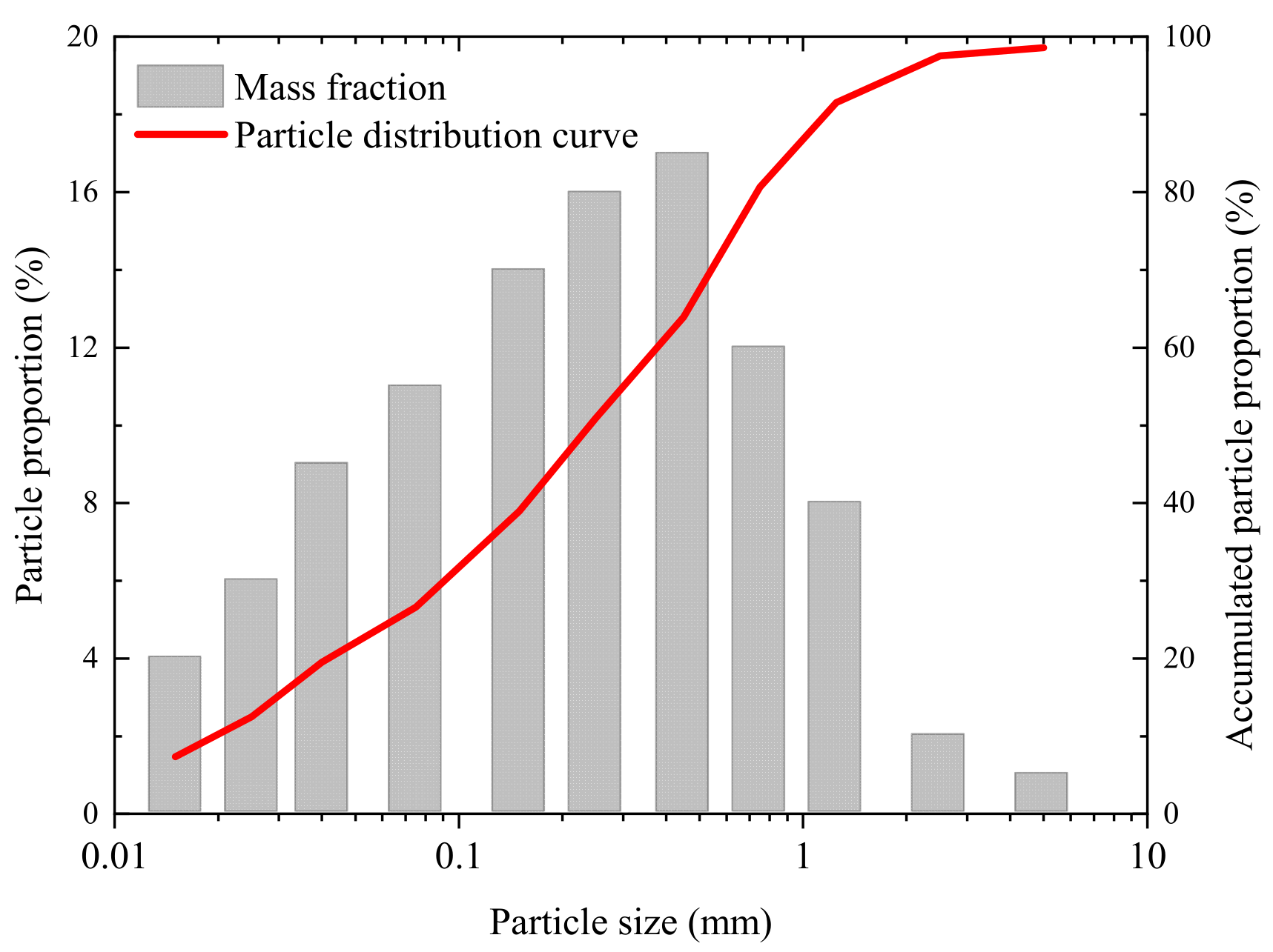
2.1.1. Coal Gangue
2.1.2. Cementitious Agent
2.1.3. Mixing Water
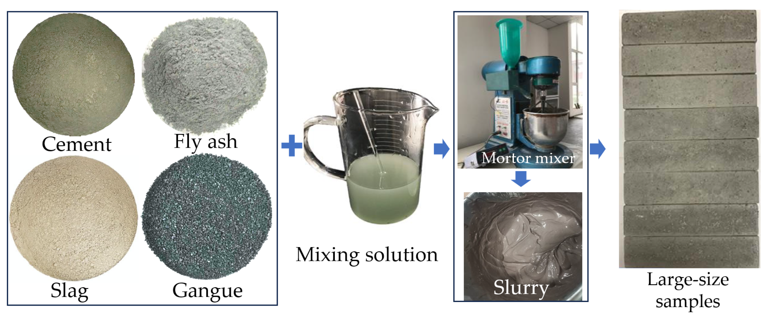
2.2. Specimen Preparation
2.3. Methods
3. Results
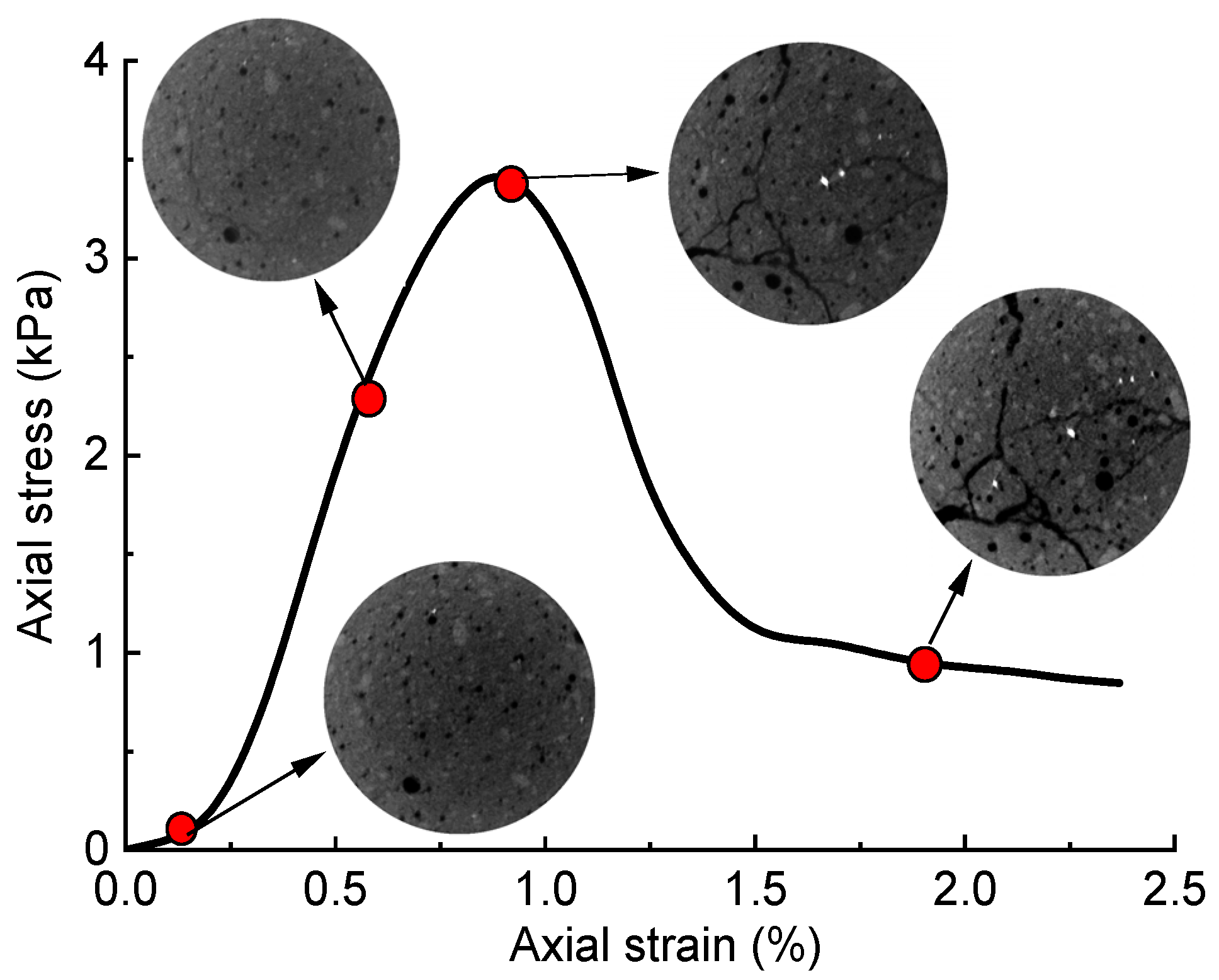
3.1. Stress–Strain (σa–εa) Curve and Failure Characteristics
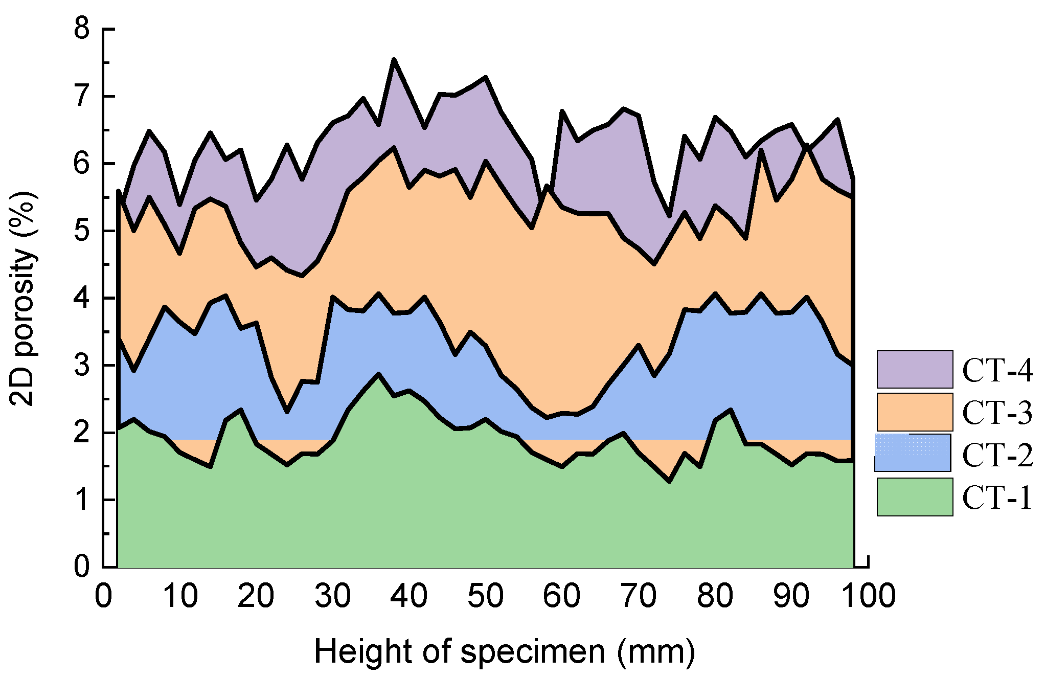
3.2. 2D Distribution Characteristics of Cracks
3.3. 3D Crack Evolution Characteristics
4. Discussion
5. Conclusions
- (1)
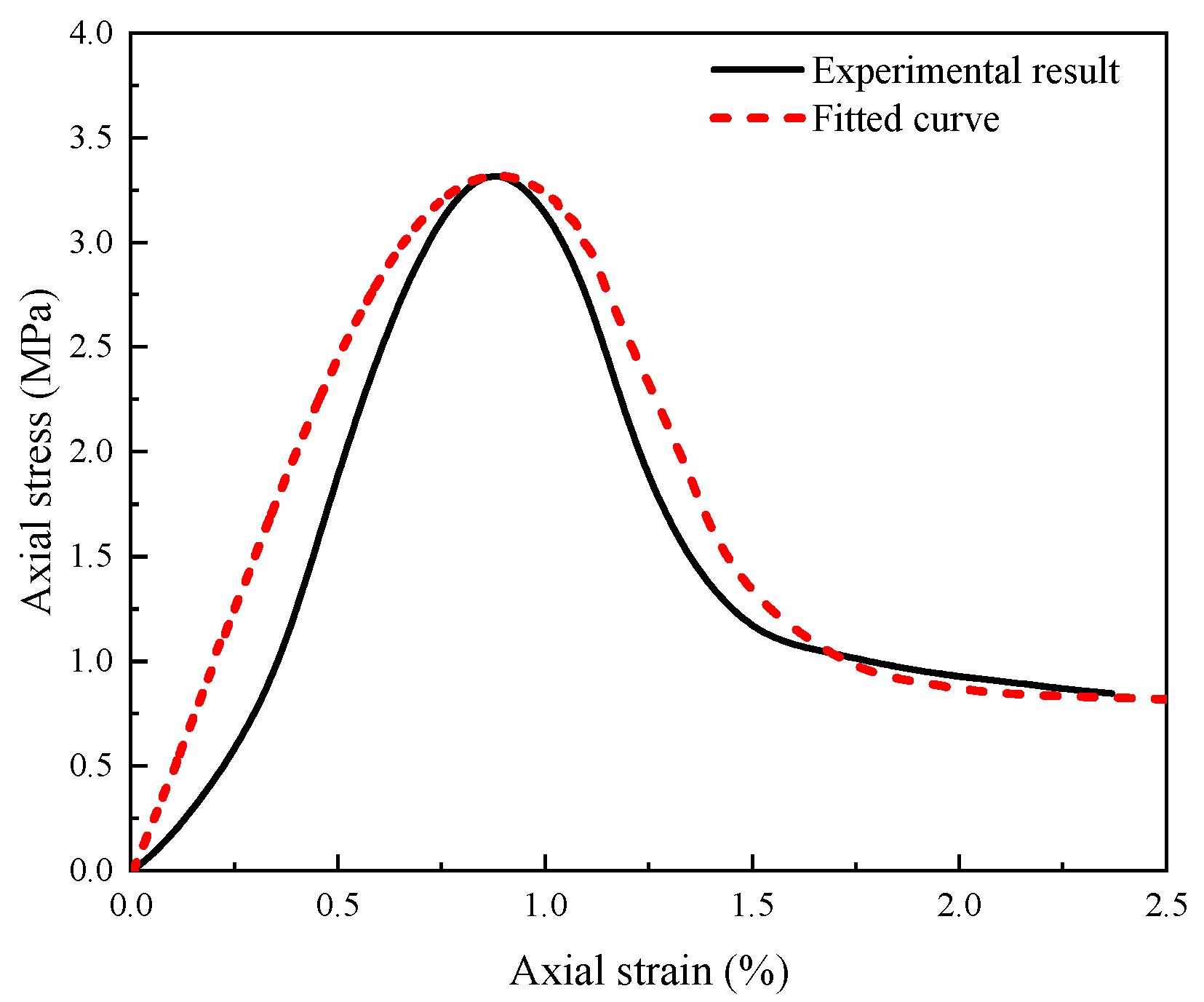
- When subjected to uniaxial loading, the σa–εa curve of CFSG cemented backfill displayed strain-softening characteristics. During the loading process, the specimens underwent four stages, namely compaction, elastic deformation, yielding, and residual deformation. The specimen exhibited an unconfined compressive strength of 3.44 MPa and a failure strain of 0.95%.
- (2)
- The 2D porosity at various heights of the specimens significantly increased with the rise in axial strain of CFSG cemented backfill. Furthermore, the dispersion of 2D porosity expanded with strain, suggesting that the heterogeneous distribution of internal cracks in the specimens was exacerbated during the compression deformation process.
- (3)
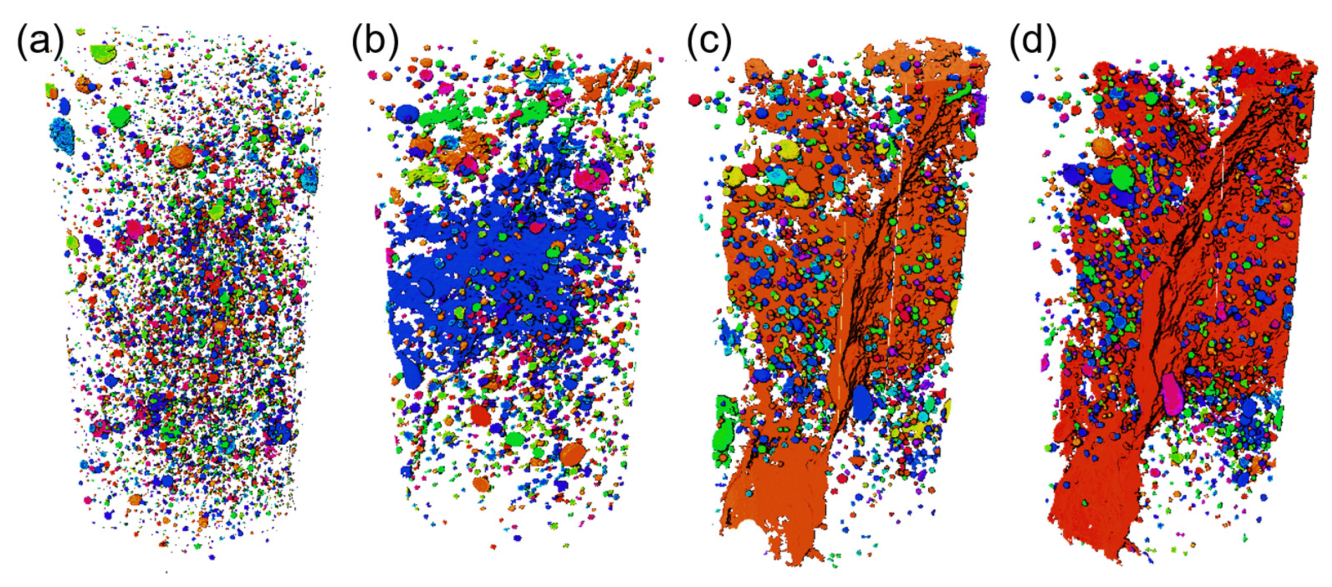
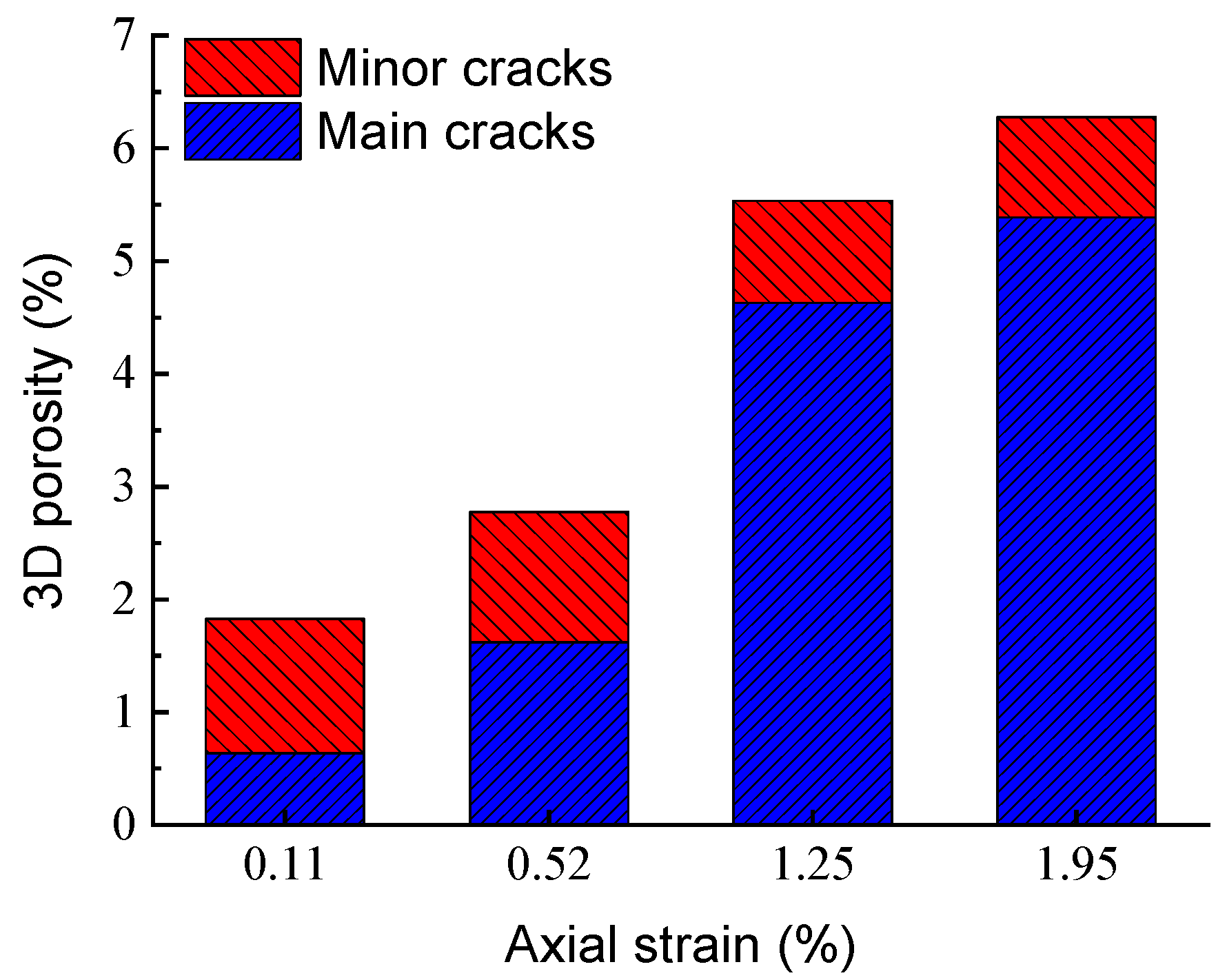
- Throughout the process of compression, 3D digital models effectively illustrated the dynamic progression of fracture surfaces emerging from the interior outward in the specimen. The volume and 3D porosity of cracks showed a gradual increase during the elastic deformation stage, followed by a rapid escalation during the yielding and residual deformation stages. Additionally, the proportion of main cracks experienced a significant rise throughout the compression process.
- (4)
- The development of microscopic fractures is the underlying cause of damage and deterioration in CFSG cemented backfill. The damage variable, derived from the volume of 3D cracks, exhibited an exponential growth pattern in response to strain. The change pattern of the damage variable suggests that the structural damage in the backfill material primarily transpired during the transition from the elastic deformation to yielding deformation stages, eventually reaching a stable state in the residual deformation stage.
- (5)
- The damage evolution model, based on real-time CT scanning, accurately depicts the stress–strain relationship during uniaxial compression of the CFSG cemented backfill. Therefore, understanding the cracking patterns can provide valuable insights for predicting structural damage and designing more resilient backfill materials for various mine applications.
Author Contributions
Funding
Data Availability Statement
Acknowledgments
Conflicts of Interest
References
- Wang, D.; Shi, C.; Farzadnia, N.; Shi, Z.G.; Jia, H.F.; Ou, Z.H. A review on use of limestone powder incement-based materials: Mechanism, hydration and microstructures. Constr. Build. Mater. 2018, 181, 659–672. [Google Scholar] [CrossRef]
- Xue, G.L.; Yilmaz, E.; Song, W.D.; Cao, S. Mechanical, flexural and microstructural properties of cement-tailingsmatrix composites: Effects of fiber type and dosage. Compos. Part B Eng. 2019, 172, 131–142. [Google Scholar] [CrossRef]
- Walske, M.L.; McWilliam, H.; Doherty, J.; Fourie, A. Influence of cur-ing temperature and stress conditions on mechanical properties of cementing paste backfill. Can. Geotech. J. 2016, 53, 148–161. [Google Scholar] [CrossRef]
- Heikal, M.; Ali, M.A.; Ghernaout, D.; Elboughdiri, N.; Ghernaout, B.; Bendary, H.I. Prolonging the Durability of Maritime Constructions through a Sustainable and Salt-Resistant Cement Composite. Materials 2023, 16, 6876. [Google Scholar] [CrossRef]
- Ye, G.; Liu, X.; De Schutter, G.; Poppe, A.M.; Taerwe, L. Influence of limestone powder used as filler in SCCon hydration and microstructure of cement pastes. Cem. Concr. Res. 2007, 29, 94–102. [Google Scholar] [CrossRef]
- Heikal, M.; ·Ali, M.A.; ·Ibrahim, S.M.; ·Bendary, H.I. Sustainable composite cement prepared by two different types of iron slag. J. Mater. Cycles Waste 2024, 26, 331–345. [Google Scholar] [CrossRef]
- Zhao, K.; Li, W.; Ding, H.; Zeng, P.; Xiang, W.; Zhang, M.; Liu, Z.; Li, Y. Experimental study on themechanical and acoustic characteristics of cemented backfillwith unclassified tailings at different curing ages under uniaxia lcompression. Sustainability 2023, 15, 7177. [Google Scholar] [CrossRef]
- Koohestani, B.; Belem, T.; Koubaa, A.; Bussière, B. Experimental investigation into the compressive strength development of cemented paste backfill containing Nano-silica. Cem. Concr. Compos. 2016, 72, 180–189. [Google Scholar] [CrossRef]
- Qiu, J.-P.; Yang, L.; Xing, J.; Sun, X.-G. Analytical Solution for Determining the Required Strength of Mine Backfill Based on its Damage Constitutive Model. Soil Mech. Found. Eng. 2018, 54, 371–376. [Google Scholar] [CrossRef]
- Hu, J.; Ren, Q.; Jiang, Q.; Gao, R.; Zhang, L.; Luo, Z. Strength Characteristics and the Reaction Mechanism of Stone Powder Cement Tailings Backfill. Adv. Mater. Sci. Eng. 2018, 2018, 8651239. [Google Scholar] [CrossRef]
- An, R.; Zhang, X.; Wang, Y.; Chen, C.; Chen, X. Dynamic evolution of cracks in slag-modified soil under uniaxial loading using real-time X-ray computed tomography. J. Mater. Civ. Eng. 2023, 35, 14491. [Google Scholar] [CrossRef]
- Jabłońska, B.; Kityk, A.V.; Busch, M.; Huber, P. The structural and surface properties of natural and modified coal gangue. J. Environ. Manag. 2017, 190, 80–90. [Google Scholar] [CrossRef]
- Zhou, X.; Zhang, Y.; Ha, Q. Real-time computerized tomography (CT) experiments on limestone damage evolution during unloading. Theor. Appl. Fract. Mech. 2008, 50, 49–56. [Google Scholar] [CrossRef]
- Yuan, Z.; Gao, L.; Chen, H.; Song, S. Study on Settlement ofSelf-Compacting Solidified Soil inFoundation Pit Backfilling Based onGA-BP Neural Network Model. Buildings 2023, 13, 2014. [Google Scholar] [CrossRef]
- Wang, Y.; Li, X.; Wu, Y.F.; Lin, C.; Zhang, B. Experimental study on meso-damage cracking characteristics of RSA by CT test. Environ. Earth Sci. 2015, 73, 5545–5558. [Google Scholar] [CrossRef]
- Liu, K.; Zhang, X.; Chen, Y. Extraction of coal and gangue geometric features with multifractaldetrending fluctuation analysis. Appl. Sci. 2018, 8, 463. [Google Scholar] [CrossRef]
- Querol, X.; Izquierdo, M.; Monfort, E.; Alvarez, E.; Font, O.; Moreno, T.; Alastuey, A.; Zhuang, X.; Lu, W.; Wang, Y. Environmental characterization of burnt coal gangue banks at Yangquan, Shanxi Province, China. Int. J. Coal Geol. 2008, 75, 93–104. [Google Scholar] [CrossRef]
- Yang, J.; Yang, B.; Yu, M. Pressure Study on Pipe Transportation Associated with Cemented Coal Gangue Fly-Ash Backfill Slurry. Appl. Sci. 2019, 9, 512. [Google Scholar] [CrossRef]
- Li, J.; Huang, Y.; Chen, Z.; Zhang, J.; Jiang, H.; Zhang, Y. Characterizations of macroscopic deformation and particle crushing of crushed gangue particle material under cyclic loading: In solid backfilling coal mining. Powder Technol. 2019, 343, 159–169. [Google Scholar] [CrossRef]
- Yilmaz, E.; Belem, T.; Benzaazoua, M.; Kesimal, A.; Ercikdi, B. Evaluation of the strength properties of deslimed tailings paste backfill. Miner. Resour. Eng. 2007, 12, 129–144. [Google Scholar]
- Zhou, C.; Liu, G.; Wu, S.; Lam, P.K.S. The environmental characteristics of usage of coal gangue in bricking-making: A case study at Huainan, China. Chemosphere 2014, 95, 274–280. [Google Scholar] [CrossRef]
- Li, Y.; Yao, Y.; Liu, X.; Sun, H.; Ni, W. Improvement on pozzolanic reactivity of coal gangue by integrated thermal and chemical activation. Fuel 2013, 109, 527–533. [Google Scholar] [CrossRef]
- Bian, Z.; Dong, J.; Lei, S.; Leng, H.; Mu, S.; Wang, H. The impact of disposal and treatment of coal mining wastes on environment and farmland. Environ. Geol. 2009, 58, 625–634. [Google Scholar] [CrossRef]
- Wang, J.; Qin, Q.; Hu, S.; Wu, K. A concrete material with waste coal gangue and fly ash used for farmland drainage in high groundwater level areas. J. Clean. Prod. 2016, 112, 631–638. [Google Scholar] [CrossRef]
- Wu, Y.; Wang, D.; Wang, L.; Shang, Z.; Zhu, C.; Wei, J.; Yuan, A.; Zhang, H.; Zeng, F. An analysis of the meso-structural damage evolution of coal using X-ray CT and a gray-scale level co-occurrence matrix method. Int. J. Rock Mech. Min. Sci. 2022, 152, 105062. [Google Scholar] [CrossRef]
- Wang, C.W.X. In situ X-ray computed tomography (ct) investigation of crack damage evolution for cemented paste backfill with marble waste block admixture under uniaxial deformation. Arab. J. Geosci. 2020, 13, 1018. [Google Scholar] [CrossRef]
- An, R.; Wang, Y.X.; Zhang, X.; Chen, C.; Liu, X.; Cai, S. Quantitative characterization of drying-induced cracks and permeabilityof granite residual soil using micron-sized x-ray computed tomography. Sci. Total Environ. 2023, 876, 163213. [Google Scholar] [CrossRef]
- Li, Y.; Cui, H.; Zhang, P.; Wang, D.; Wei, J. Three-dimensional visualization and quantitative characterization of coal fracture dynamic evolution under uniaxial and triaxial compression based on μCT scanning. Fuel 2020, 262, 116568. [Google Scholar] [CrossRef]
- Sun, X.; Li, X.; Zheng, B.; He, J.; Mao, T. Study on the progressive fracturing in soil and rock mixture under uniaxial compression conditions by CT scanning. Eng. Geol. 2020, 279, 105884. [Google Scholar] [CrossRef]
- Sun, W.; Wu, A.; Hou, K.; Yang, Y.; Liu, L.; Wen, Y. Real-time observation of meso-fracture process in backfill body during mine subsidence using X-ray CT under uniaxial compressive conditions. Constr. Build. Mater. 2016, 113, 153–162. [Google Scholar] [CrossRef]
- Duan, Y.; Li, X.; Zheng, B.; He, J.; Hao, J. Cracking Evolution and Failure Characteristics of Longmaxi Shale Under Uniaxial Compression Using Real-Time Computed Tomography Scanning. Rock Mech. Rock Eng. 2019, 52, 3003–3015. [Google Scholar] [CrossRef]
- Li, Y.; Xue, L.; Wu, X. Study on acoustic emission and X-ray computed-tomography characteristics of shale samples under uniaxial compression tests. Environ. Earth Sci. 2019, 78, 173. [Google Scholar] [CrossRef]
- Wang, Y.; Li, C.; Hu, Y. 3D image visualization of meso-structural changes in a bimsoil under uniaxial compression using X-ray computed tomography (CT). Eng. Geol. 2019, 248, 61–69. [Google Scholar] [CrossRef]
- Song, Y.; Cao, J.; Ding, W.; Song, Z.; Liu, H.; Huang, S.; Zhu, W. Influence of peat soil environment on mechanical properties of cement-soil and its mechanism. Sustainability 2023, 15, 4580. [Google Scholar] [CrossRef]
- Wang, J.; Xing, M.; Yang, X.; Jiao, H.; Chen, F.; Yang, L.; Yu, J.; Fu, Y. Review on the Influence andControl of Sulfur-Containing Tailingson the Strength of Cemented Backfillin Metal Mines. Buildings 2023, 13, 51. [Google Scholar] [CrossRef]
- Meng, Q.; Wu, K.; Zhou, H.; Qin, Q.; Wang, C. Mesoscopic damage evolution of coral reef limestone based on real-time CT scanning. Eng. Geol. 2022, 307, 106781. [Google Scholar] [CrossRef]
- Li, X.; Lu, Y.D.; Zhang, X.Z.; Lu, Y.C.; Yang, Y.H. Pore-fissure identification and characterization of paleosol based on X-ray computed tomography. Bull. Soil Water Conserv. 2018, 38, 224–230+239. [Google Scholar]
- Zhao, Y.; Ling, X.; Gong, W.; Li, P.; Li, G.; Wang, L. Mechanical properties of fiber-reinforced soil under triaxial compression and parameter determination based on the Duncan-Chang model. Appl. Sci. 2020, 10, 9043. [Google Scholar] [CrossRef]
- Fleury, M.P.; Kamakura, G.K.; Pitombo, C.S.; Cunha, A.L.B.N.; Ferreira, E.B.; Lins da Silva, J. Assessing and predicting geogridreduction factors after damageinduced by dropping recycledaggregates. Sustainability 2023, 15, 9942. [Google Scholar] [CrossRef]
- Xie, S.; Lin, H.; Chen, Y.; Yong, R.; Xiong, W.; Du, S. A damage constitutive model for shear behavior of joints based on determination of the yield point. Int. J. Rock Mech. Min. Sci. 2020, 128, 104269. [Google Scholar] [CrossRef]


| Raw Materials | Gangue | Cement | Fly Ash | Water | Water-Reducing Agent |
|---|---|---|---|---|---|
| Value | 29.40 | 41.54 | 21.01 | 20.53 | 2.71 |
| Scanning Time | Axial Force (kN) | Axial Displacement (mm) | Stress (MPa) | Strain (%) | Loading Time (min) |
|---|---|---|---|---|---|
| 1 | 0.092 | 0.051 | 0.05 | 0.052 | 0.5 |
| 2 | 4.212 | 0.245 | 2.12 | 0.252 | 2.25 |
| 3 | 6.792 | 1.052 | 3.44 | 0.952 | 4.55 |
| 4 | 1.875 | 1.898 | 0.95 | 1.955 | 7.83 |
| Scanning Point | Deformation Stage | Average Crack Area/mm2 | Average 2D Porosity/% | Variance/% |
|---|---|---|---|---|
| CT-1 | elastic | 0.384 | 1.94 | 9.72 |
| CT-2 | elastic | 0.635 | 3.23 | 24.55 |
| CT-3 | plastic | 1.025 | 5.21 | 38.94 |
| CT-4 | plastic | 1.253 | 6.38 | 40.42 |
Disclaimer/Publisher’s Note: The statements, opinions and data contained in all publications are solely those of the individual author(s) and contributor(s) and not of MDPI and/or the editor(s). MDPI and/or the editor(s) disclaim responsibility for any injury to people or property resulting from any ideas, methods, instructions or products referred to in the content. |
© 2024 by the authors. Licensee MDPI, Basel, Switzerland. This article is an open access article distributed under the terms and conditions of the Creative Commons Attribution (CC BY) license (https://creativecommons.org/licenses/by/4.0/).
Share and Cite
Song, B.; Li, H.; An, R.; Zhang, X.; Zhou, Z. Experimental Study on the Strength and Damage Characteristics of Cement–Fly Ash–Slag–Gangue Cemented Backfill. Buildings 2024, 14, 1411. https://doi.org/10.3390/buildings14051411
Song B, Li H, An R, Zhang X, Zhou Z. Experimental Study on the Strength and Damage Characteristics of Cement–Fly Ash–Slag–Gangue Cemented Backfill. Buildings. 2024; 14(5):1411. https://doi.org/10.3390/buildings14051411
Chicago/Turabian StyleSong, Baofeng, Heyu Li, Ran An, Xianwei Zhang, and Zefeng Zhou. 2024. "Experimental Study on the Strength and Damage Characteristics of Cement–Fly Ash–Slag–Gangue Cemented Backfill" Buildings 14, no. 5: 1411. https://doi.org/10.3390/buildings14051411
APA StyleSong, B., Li, H., An, R., Zhang, X., & Zhou, Z. (2024). Experimental Study on the Strength and Damage Characteristics of Cement–Fly Ash–Slag–Gangue Cemented Backfill. Buildings, 14(5), 1411. https://doi.org/10.3390/buildings14051411