Article

A BIM-Based Bar Bending Schedule Generation Algorithm with Enhanced Accuracy

1
Department of Architectural Engineering, Kyung Hee University, Yongin-si 17104, Republic of Korea
2
SK Ecoplant Co., Ltd., Jongno-gu, Seoul 03143, Republic of Korea
3
Department of R&D, Earth Turbine Co., Ltd., Dong-gu, Daegu 41057, Republic of Korea
*
Author to whom correspondence should be addressed.
Buildings 2024, 14(5), 1207; https://doi.org/10.3390/buildings14051207
Submission received: 28 March 2024 / Revised: 16 April 2024 / Accepted: 18 April 2024 / Published: 24 April 2024
(This article belongs to the Special Issue BIM-Based Construction Management: Trends and Prospects)

Abstract

:
Rebar quantity estimation is pivotal for determining the cost of construction projects and is essential for bidding purposes. A bar bending schedule plays a crucial role by providing rebar information and bending instructions, facilitating efficient procurement. Traditional methods, which rely on manually extracting data from 2D (two-dimensional) drawings, are error-prone and hinder construction productivity. This study utilized a special length approach to yield optimal rebar consumption, resulting in a total rebar order of 19,582.427 t and minimizing rebar waste to 0.77%. Additionally, this method saved 3000.22 t of rebar compared to traditional methods, using only stock lengths. To enhance the accuracy and efficiency, a 3D (three-dimensional) model was developed in a Building Information Modeling (BIM) environment to prepare a Bar Bending Schedule (BBS) automatically, integrated with an Application Programming Interface (API) for data entry to eliminate manual errors. The efficacy of the proposed algorithm was confirmed by comparing the rebar quantities it generated with those obtained from optimization calculations. The results demonstrated a mean absolute error of 0.017 and a mean absolute percentage error of 1.13%, validating the algorithm’s precision. Furthermore, this method reduced the manpower required for BBS preparation by 33.33%, highlighting its potential to revolutionize construction workflow efficiency and accuracy.

1. Introduction

Cost estimation is a crucial step in assessing project expenses and making informed decisions prior to the commencement of the construction stage. Rebar cost constitutes a significant portion of the overall project cost in reinforced concrete structures, with estimates ranging from 16% to 20% [1,2]. Estimating rebar quantity requires meticulous calculation since it can lead to greater rebar consumption than required for the project, resulting in increased material waste and additional costs [3]. The quantity of rebar is established by the Bar Bending Schedule (BBS), which is provided by the structural designer or acquired from the steel mill [4]. Preparing the BBS requires comprehensive data to accurately determine the specifications of the rebar needed, including the length, quantity, and shape of each rebar. It also calculates the overall weight of all rebars required for a building’s structure [5].
One factor that influences the efficiency of the BBS is the building code provision for rebar detailing, such as regulations for lap splices, development length, hook lengths, bar spacing, and concrete cover. The building codes used are varied depending on the location or country where the project occurs. For instance, in the United States, the guidelines for rebar detailing are provided by ACI [6], in the United Kingdom, the guidelines are provided by BSI [7] and Eurocode [8], while KDS [9] is utilized in the Republic of Korea, and JSCE [10] in Japan. In addition, bend deduction is crucial to obtain the exact rebar length required for a specific rebar shape [3,11]. The rebar tends to elongate more than its length when it is bent. An excess length of rebar is yielded unless the bend deduction is considered for cutting the rebar. Hence, the building codes and bend deduction are crucial for improving the precision of the BBS and the estimation of rebar quantities.
Structural design and analysis are conducted after the completion of architectural design, along with the preparation of drawings and reports [12], which is time-consuming and labor-intensive. In the conventional method of BBS preparation, the estimator must check every drawing meticulously to determine rebar quantities, ensuring not to omit or double-count items [13]. Waste in construction materials typically occurs during the procurement phase, material handling phase, and design phase [3,14]. Although safety factors are considered in the structural design, the designer may increase the quantity or length of rebars as additional safety measures [3]. Even though excess rebar quantity is estimated to be more than what is required in the design stage, a reliable and accurate BBS can minimize rebar waste [15]. Therefore, it is essential to adopt advanced technologies to enhance the accuracy of the BBS and to optimize the estimation process.
Building Information Modeling (BIM) has gained significant traction in Architecture, Engineering, and Construction (AEC) due to its capabilities in the coordination, visualization, and simulation of building projects [13,16]. BIM-based software applications, such as Revit 2024 can retrieve data from the model for the quantity take-off to estimate cost [16]. BIM models store dimensional data within the 3D model itself and measurements and material quantities can be extracted from the model, reducing the time spent on take-offs by up to 80% compared to traditional methods [13]. BIM also provides consistent updates of data information to the changes made to the model and enables the rebar arrangement automatically, generating the required rebar quantity. To ensure the required length and quantity of rebars for BBS, BIM can be implemented at the design stage once the structural analysis is completed. However, the BIM model cannot provide all the data requirements for quantity estimation, necessitating manual data input to the model.
The Application Program Interface (API) has increased in popularity in recent years due to the facilities it offers for BIM applications. API in BIM software (Revit 2024) operates by providing a set of tools, functions, and methods that allow developers to interact with the software through programming languages such as Visual C# or Visual Basic.NET (VB.NET) [17]. APIs can be employed to import data and update the model automatically or exchange information between the BIM and other software systems. This capability is crucial in ensuring the accuracy of material estimation in BIM applications [16,18]. For instance, Wang and Lu [19] employed Revit API for the automation of the BIM model creation by linking with a database of the components using C# programming language and Revit 2018 API, ensuring the precision and reliability of design projects. Moreover, APIs facilitate automating iterative tasks in the modeling process. Han et al. [20] leveraged a Revit secondary development application, developed through API, to automate the repetitive tasks involved in modeling duct systems, enhancing the efficiency of the BIM process, and notably, reducing the modeling time.
Multiple research projects have been conducted on rebar waste optimization on columns [21,22], beams [12,23], and diaphragm walls [24], which are the main structural members of the construction industry. Among them, diaphragm walls consume an enormous amount of rebar, as well as require diverse types of rebar for different purposes in fabrication, including links, stiffeners, spacers, fixing rebars, suspension hooks, starter bars, etc. It is also essential to optimize rebar waste and usage in diaphragm walls since they are constructed in large infrastructures such as bridges, tunnels, and subway stations. Therefore, the diaphragm wall is a suitable case subject for the BBS generation algorithm. Once the proposed algorithm is verified in the diaphragm wall’s BBS, it can be applied to other structural elements, contributing to its practical implementation in the ACE industry to save rebar waste and cost.

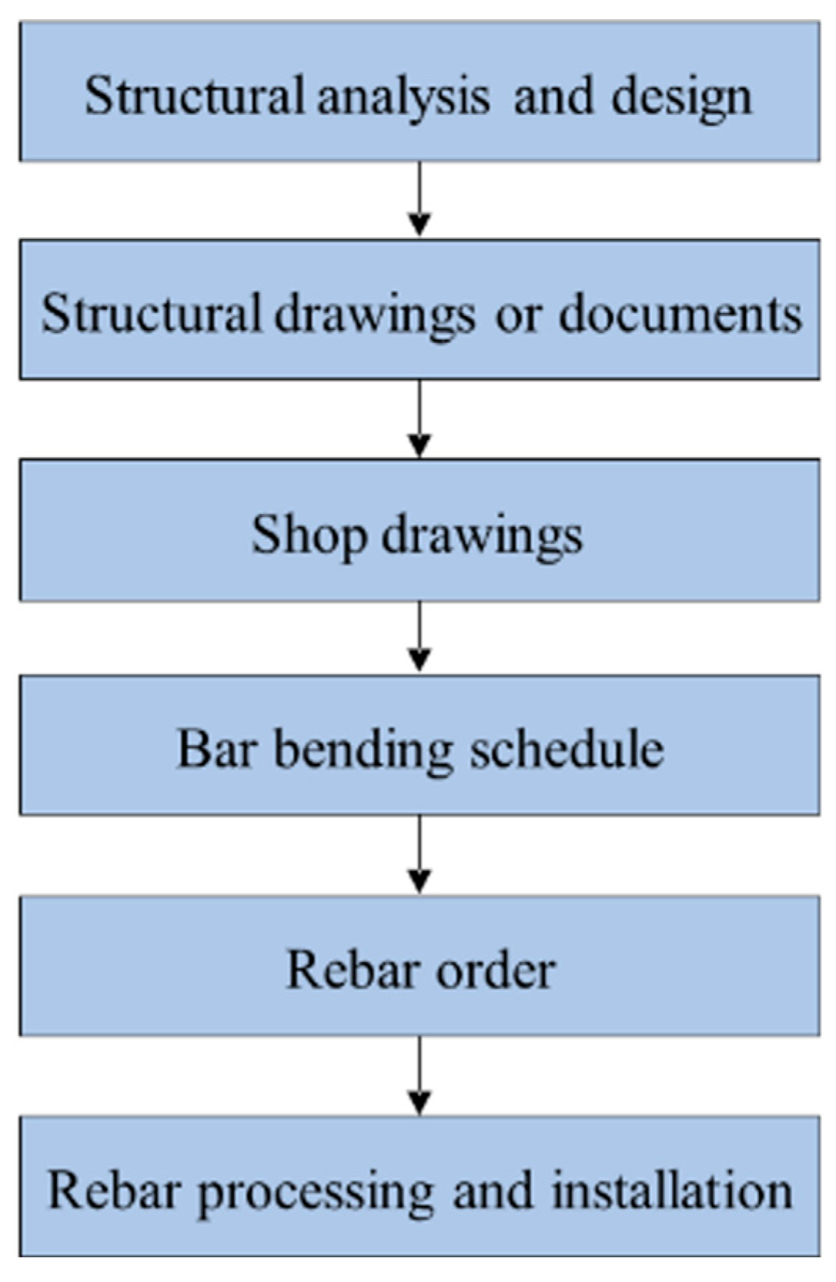
1.1. Rebar Procurement

Before enhancing the efficiency of a BBS, it is necessary to understand the existing process of rebar procurement. Rebar procurement comprises various critical steps. As depicted in Figure 1, after the completion of structural analysis and design, 2D structural drawings and documents are created, followed by shop drawings. These project shop drawings are analyzed to prepare a BBS which determines the required rebar quantities for a particular project. The BBS needs to be meticulously prepared to avoid wastage and unnecessary additional costs [25]. Estimating rebar quantity and cost is also vital for bidding projects [12]. The next step is to order the required rebars, ensuring that the ordered rebar quantity matches the calculated demand accurately to prevent shortages or surplus [26], minimizing the occurrence of waste. Once the rebars have been ordered, the rebar processing and installation can be conducted.
A BBS is essential for rebar procurement as it specifies the required quantity of rebar for cost estimation and provides instructions for fabricating rebar shapes. The subsequent step, often referred to as rebar work, involves preparing the rebar for use in a construction project, which includes cutting, bending, and storing the rebar pieces according to the project requirements. Efficient coordination is essential in the construction phase to ensure that rebars are correctly and safely installed. The entire process of rebar procurement requires meticulous scheduling and coordination to avoid delivery delays, requiring collaboration between various organizations, such as suppliers, logistics, project teams, and onsite construction teams.

1.2. Related Literature

The primary reason for enhancing the accuracy of the BBS is to prevent the misuse of rebars and reduce material waste and cost in construction projects. Nigussie and Chandrasekar [3] conducted a questionnaire survey regarding the factors that influence rebar wastage on sites. One factor involves not optimizing the use of stock rebars supplied by manufacturers. In practice, the bar benders cut the rebar longer than the given length to accommodate for any mistakes or uncertainties in the construction process, creating unusable short pieces and leading to unnecessary rebar wastage and material cost.
To minimize rebar waste from unusable stock length rebars, Zheng et al. [1] developed rebar-cutting patterns that complied with the target waste limit and were integrated with cost optimization. Nadoushani et al. [21] enhanced lap splice position patterns in stock lengths by allowing adjustable lap splice positions in columns and shear walls. The studies by Zubaidy [27], Nanagiri and Singh [28] utilized integer linear programming approaches to reduce cutting waste by optimizing rebar lengths available in the market. Similarly, Khondoker [29] employed mixed-integer programming, integrated with BIM, to refine cutting patterns for column rebars, generating an optimal consumption of stock length rebar. However, these methods were unable to reduce rebar wastage below the typical range of 3–5% [11,30], as their optimization was limited by the lap splice position requirements enforced by building codes [24]. Using stock-length rebars reflecting those regulations results in limited flexibility and potential material waste. Furthermore, it is difficult to follow these regulations in practice and lap splices in columns are placed on top of the floor slab to ease the construction process [31]. Therefore, rebars are often cut depending on the floor height rather than following the precise regulations, leading to additional rebar waste. The research conducted by Widjaja et al. [31] also explored the possibility of adjusting the locations of lap splices within structural members, observing that these adjustments can maintain the same level of structural strength and stability as the areas specified by the building codes.
Recent studies [12,24] utilized special length rebars to reduce rebar waste in beams and diaphragm walls. Widjaja and Kim [12] minimized rebar usage and cutting waste in beam members by a two-stage optimization algorithm using special lengths and achieved a 0.93% waste rate. The study by Rachmawati et al. [24] also resulted in near-zero rebar cutting waste by 0.77% in minimizing cutting waste in diaphragm wall rebars by a three-step heuristic algorithm, considering the special lengths and the flexibility of lap splice position. It has been sufficiently proved that special length prioritization over stock length offers a significant reduction in rebar waste. These studies used a BBS, retrieved from the BIM model as the data source, however, these studies did not mention the detailed process of the BBS preparation. This gap is critical since the optimization algorithms rely on the rebar information, especially bar lengths and number of bars, derived from the BBS. A detailed BBS preparation process ensures accurate waste calculation and facilitates the practical implementation of their findings in the construction industry.
In previous studies [32,33], the application of the API has been pivotal in the development of plugins and new user interfaces within Autodesk Revit, using programming languages such as C# and Python. Wang and Hu [32] focused on the automatic generation of rebar parametric models to enhance the modeling efficiency and accuracy for reinforced concrete columns, while Li et al. [33] developed a user interface for handling variable cross-section columns through Revit API. Additionally, studies such as those presented in [16,18] introduced a BIM-based quantity takeoff through API integration. Taghaddos et al. [18] estimated the volume and weight of different structural steel elements and piping by integrating Navisworks and API. Similarly, Sherafat et al. [16] applied API in multiple BIM applications, including Revit, Tekla, and Navisworks, to facilitate the accurate extraction of rebar quantities, demonstrating the capability to transfer models across different software platforms efficiently. Our study utilized only the Revit software (2024 version) platform by employing API for data mapping to automate the generation of a BBS, thereby minimizing manual input errors and streamlining the rebar procurement.

1.3. Research Objectives

As shown in Figure 1, the current practice of preparing a BBS relies on extracting information from 2D computer-aided design (CAD), such as AutoCAD drawings or paper-based shop drawings [16,34], which often leads to wrong interoperation and deficits of wrong input via manual tasks, consequently, resulting in miscalculations of exact rebar quantities. Rachmawati et al. [24] achieved Near-Zero Rebar Cutting Waste (N0RCW) for diaphragm walls using a three-step optimization algorithm, applied to rebar information extracted from the BIM model (BBS). However, the study lacked clarity on the process of preparing the rebar data within the BIM model, potentially limiting the generalizability of their findings, as well as leading to inaccuracies that can arise due to the suboptimal rebar combinations.
To address this, the proposed workflow incorporates several key stages, as depicted in Figure 2:
  • Structural design and analysis results which establish the structural requirements for reinforcement.
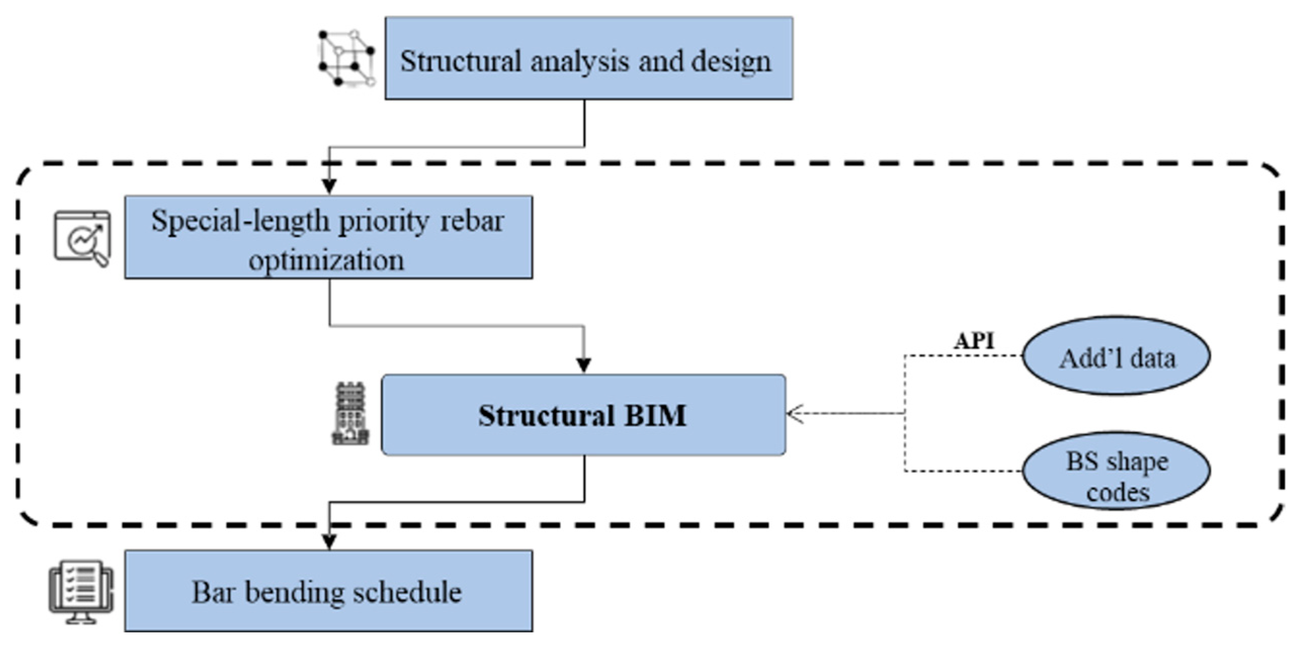
  • An enhanced BIM-based BBS generation algorithm, integrated with a special length prioritization strategy, considering optimization before model creation. This optimization-first approach minimizes data transitions, thereby reducing error propagation and ensuring consistency between the BBS and subsequent rebar procurement.
  • A structural 3D model was created incorporating the optimized rebar information.
  • The BBS is prepared with enhanced accuracy by utilizing the Revit API within the BIM environment, additional information such as BS shape codes [35] (which influence bend deductions and rebar usage) can be linked. This enables the automatic generation of highly accurate BBS data, including precise rebar quantities.
Consequently, the proposed approach is further expected to reduce the time and quantity of manpower required compared to the manually prepared method, in addition to the enhanced accuracy. This research serves as a pioneering effort in automating BBS generation which considers the strategic use of special-length rebar for improved efficiency.

2. Materials and Methods

Figure 3 illustrates the development of the descriptive algorithm in this study to automatically generate a BBS by leveraging special-length rebar optimization and BIM. The figure is divided into two parts, with the right side detailing the information collected at each step.
Part 1 outlines the process of special-length-priority rebar optimization:
  • The initial step involves preparing the main dataset from structural design and analysis or in some cases, structural drawings.
  • The data set encompasses details about the building’s structural framework, including dimensions, locations, and connections of structural members, as well as rebar information such as bar size, bend diameter, bar spacing, the quantity of rebar, and the concrete cover of each element.
  • The prepared information is cross-verified with the regulations of the relevant building codes to ensure compliance with structural integrity.
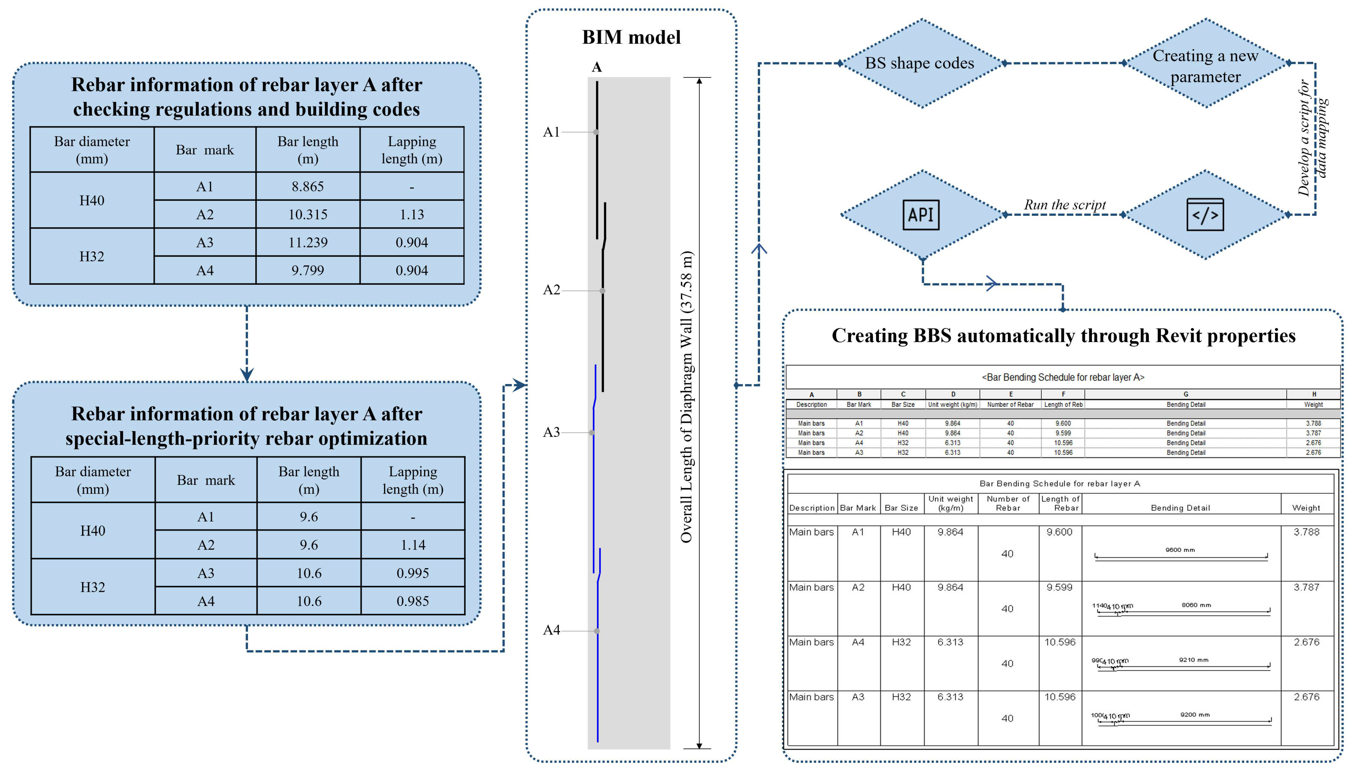
  • The rebars were optimized into special lengths to enhance rebar utilization and minimize cutting waste, generating special lengths and amounts of rebars.
Part 2 details the process of BBS preparation within a BIM model.
  • A detailed 3D structural BIM model is created in Autodesk Revit, with rebars meticulously added to each element, paying special attention to lapping areas, anchorage lengths, and bends.
  • The rebar arrangements are thoroughly analyzed, and each rebar is categorized by type, bar mark, and rebar shape.
  • Consequently, each identified rebar shape is assigned a BS shape code, which calculates the exact length of the rebar, accounting for bend deductions.
  • As the BIM model does not inherently provide all the necessary data for calculating rebar quantities, additional data, such as rebar unit weight, is linked to the BIM model using the Revit 2024 API, facilitated by a custom Python script based on Python 3.1.2.
  • Once the BIM model was completed with all necessary details, a BBS was generated automatically through managing Revit properties. The generated BBS displays rebar specifications, including bar type, bar mark, bar size, number of rebars, bar length, bar shape with segment dimensions, and bar weight.
The algorithm’s effectiveness was verified in a case study to automate a BBS, and the generated rebar quantities were compared to the optimization results for error analysis.

2.1. Special-Length-Priority Rebar Optimization for Diaphragm Wall Rebars

2.1.1. Optimization of Main Rebars

The diaphragm wall is typically reinforced with different diameter rebars throughout the entire depth with smaller diameter rebars as the wall becomes deeper. Before model creation, all rebars, particularly the continuously arranged rebars of the same diameter within each layer, were optimized for special lengths. This optimization focused on the main rebars due to their continuous arrangement and significant impact on material usage. Equations (1)–(3) were adapted from the study presented in [24] for special length optimization.
L t o t a l = i = 1 r L r e b a r _ i
n r e b a r = L t o t a l L r e f
L s p e c i a l = L t o t a l n r e b a r
where L t o t a l is the total length of the same diameter wall rebars; L r e b a r _ i is the length of rebar i; and r is the summation’s upper boundary, corresponding to the total count of rebar included in the overall length computation; n r e b a r is the revised quantity of required rebars and L r e f is the optimal reference length (maximum rebar length available on the market); and L s p e c i a l is the special length.
Equation (1) calculates the total length of the same diameter rebars in each layer. Equation (2) determines the revised quantity of the required rebars in the total length by dividing the total length by the optimal reference length. In the Republic of Korea, for example, 12 m is regarded as the maximum market length. Special lengths were calculated in Equation (3), by dividing the total length by a revised quantity required rebar.

2.1.2. Optimization of Remaining Rebars

To achieve optimal rebar usage and the least cutting waste, the remaining rebars were also grouped in special length cutting patterns. This was performed by using the minimization function in Equation (4), adopted from the study presented in [30]. Equations (5)–(9) are the constraints for special length order requirements. l i in Equation (5) represents the cutting pattern of rebars of the same diameter ( r 1 + r 2 + + r n ). Equation (6) ensures that the number of cutting patterns ‘i’ is a whole number and greater than zero. According to Equation (7), the special length must not be shorter than the minimum length ( L m i n ) and not longer than the maximum length ( L m a x ). The total ordered rebar quantity must surpass the minimum rebar quantity for a special length order, as shown in Equation (8). Furthermore, Equation (9) indicates that the loss rate produced must remain below the designated target loss rate. As outlined by Lee et al. [30], a special length can be ordered within a range of 6 m to 12 m, with a minimum order of 50 t of rebar in the Republic of Korea.
M i n i m i z e   f X i = i = 1 N L s p i n i l i n i L s p i n i
l i L s p i ,   l i = r 1 + r 2 + + r n
0   <   n i , i = 1 , 2 , 3 , , N
L m i n   L s p i L m a x
Q s p Q t o t a l
ε ε t
where L s p i is the special-length cutting pattern; l i is the length of the cutting pattern i obtained by combining different rebar lengths; n i represents the number of rebar combinations sharing the same cutting pattern i; L m i n is the minimum length required for the special length orders; L m a x is the maximum length required for the special length orders; Q s p is the minimum rebar quantity required for special length orders; Q t o t a l represents the total quantity of rebar purchased; ε is the rebar loss rate of the special length cutting pattern; and ε t is the target loss rate, which is set to be below 1%.

2.2. Revit API Application

Revit API is a set of tools and functions provided by Autodesk Revit for BIM. It can be used for automating repetitive tasks, checking errors automatically, extracting data, inserting additional data, and integrating with other applications. Revit API can be managed through programming using several programming languages such as VB.NET, C#, and Python languages. To perform a particular task, the script or program can be developed using an environment such as Visual Studio or Revit Add-Ins which interact with the software through API. It is necessary to ensure that the Autodesk Revit Program directory contains two DLLs (Dynamic Link Libraries)—RevitAPI.dll and RevitAPIUI.dll [36]. The initial part encompasses techniques for interacting with Revit’s application, documents, elements, and parameters at the database level, while the latter part covers the interfaces used for altering and personalizing the Revit user interface.
Rachmawati et al. [24] performed rebar quantity take-off in the Revit model by inserting the required data of rebar unit weights into the model manually. This method requires more time and is error-prone if the project data is complicated. In this study, the external unit weight data required for quantity calculation was linked to the model through Revit API, in which the data was assigned to the respective rebar elements, eliminating the manual input and reducing the time required.

3. Case Application

3.1. Case Study Overview

Diaphragm walls, serving as crucial structural components, utilize the prefabricated rebar cages, incorporating various elements like main rebars, links, spacers, stiffeners, and additional rebars for hanging and lifting. This approach, due to the extensive rebar usage and intricate detailing, stands as a good example of comprehensive BBS preparation. The case study diaphragm wall is part of an interchange station, comprising 293 primary wall panels. Each panel measures 6 m in length, 1 m in thickness, and 37.58 m in overall depth. Three-floor levels are connected to the diaphragm wall. High-strength steel rebars, with a tensile grade of 500 MPa (denoted as ‘H’), were consistently employed for the entire reinforcement. The rebar cage itself utilized six distinct rebar diameters: H40, H32, H25, H20, H16, and H13. Table 1 summarizes the main characteristics of the primary wall panel.
The primary wall employed two identical rebar cages, each built from four sections. Within each cage, EX-links and C-links provided lateral restraint for the main vertical rebars, as demonstrated in Figure 4a. The starter bars facilitated the anchorage of the floor’s reinforcement to the cages. Other additional rebars, such as stiffeners, fixing rebars, and spacers, strengthened the cage and prevented it from deformation. As shown in Figure 4b, the main vertical rebars were organized into layers A, B, D, and E. Notably, layers A and D spanned throughout the entire rebar cage, while layers B and E terminated at the second cage section. Unique rebar marks distinguished the individual rebars, for instance, ‘A1’ indicated the rebar in layer A of the first cage. H40 and H32 diameter rebars were utilized as the main rebars: H40 in the first, second, and third cages (A1, A2, B1, B2, D1, D2, D3, E1, E2), while H32 was utilized in the third and fourth cages (A3, A4, D3a, D4).

3.2. Application of the Proposed Algorithm

Initially, the rebar specifications of the case study were checked with building code regulations for the rebar diameter, rebar cover, and lapping length to prepare the primary data source for the optimization process. For further details, the primary rebar data is presented in Table A1.

3.2.1. Special-Length-Priority Optimization

Subsequently, special-length-priority optimization was applied to the main rebars by using Equations (1)–(3). This optimization targeted the rebars of identical diameter rebars, continuously arranged in one layer, as mentioned in Section 2.1.1. For instance, rebar layer D, comprising five rebars of two distinct diameters, includes H40 rebars (D1, D2, D3), and H32 rebars (D3a, D4). According to Equation (1), the total length of the H40 rebars in layer D was calculated to be 19,180 mm. Following this, Equation (2) was used to determine the revised quantity of rebar by dividing the total length by the optimal reference length of 12 m. The special length for layer D was generated when the total length was divided by the revised number of rebars. This process of total length calculation was performed for the remaining rebar layers A, B, and E. The results of these calculations for the main rebar optimization are summarized in Table 2.
After substituting the main rebars with special lengths, cutting pattern optimization was performed on the remaining rebars according to Equations (4)–(9). Specifically, the application Cutting Optimization Pro [38] was used to automate the selection of optimal cutting patterns for rebar combinations, as outlined in Equation (5). For instance, considering the H13 rebars, a total of 3440 C-links, each measuring 1.214 m, were entered into the ‘Cutting Optimization Pro’ interface. The application then automatically calculated the cutting patterns, required quantities, and trim loss, based on the special lengths provided. A rebar length of 11 m, which is the standard length in the market but considered a special length in this study due to its 0.1 m increments, proved to be the most efficient, producing the least waste for C-links. The generated special lengths from rebar combinations of the remaining rebars are summarized in Table 3.
Once special length optimization was performed on both the main rebars and the remaining rebars of the diaphragm wall, a comprehensive analysis was conducted across 293 panels of the diaphragm wall. The findings, detailed in Table 4, indicate a range of optimized special lengths tailored to reduce rebar waste. Special lengths of 10.3 m, 9.6 m, 9.3 m, and 8.2 m were obtained for the H40 rebars; 12 m, 10.6 m, and 8.6 m for H32; 10.6 m for H25; 9.6 m for H20; 8.2 m for the H16 rebars; and 11 m for the H13 rebars, respectively. Each rebar quantity of these special lengths surpassed 50 t, thereby meeting the minimum order quantity, as well as complying with the constraints for special length order requirements, Equations (5)–(9). Despite H25 yielding the highest waste rate of 2.09%, it did not surpass the common estimated rate of 3 to 5% [30]. Additionally, the overall waste rate of the diaphragm wall was 0.77%, achieving N0RCW.
The effectiveness of the special length priority optimization was evaluated through a comparison between its findings and those obtained using the original method, which ordered rebars in standard stock lengths. This comparative analysis focused on differences in rebar usage and cutting waste, as depicted in Table 5. Initially, the original method required 22,582.65 t of rebars ordered in stock lengths. However, after implementing the optimization, the total ordered weight was reduced to 19,582.43 t. This optimization strategy, which prioritized the use of special lengths, resulted in a significant reduction of 3000.22 t of rebar, corresponding to a 13.3% decrease in rebar usage.

3.2.2. BBS Preparation in Revit

A 3D structural model of the diaphragm wall panel was created in Revit Autodesk 2024, incorporating the optimized special lengths determined for the main rebars. While the remaining rebars were also optimized for the special length cutting patterns, their individual lengths were detailed within the model, based on the primary rebar data as shown in Table A1. All the rebars were well-defined with corresponding rebar types, bar marks, and shapes, and were further enhanced by incorporating BS shape code formulas into the rebar shape parameter to facilitate bend deduction.
The BBS in this study encompassed crucial information including the description (type of rebar), bar mark, bar diameter, unit weight, number of rebars, bar length, bending instruction, and rebar weight. Notably, the conventional method entails the preparation of BBS through Revit properties after completing the structural model with a detailed rebar arrangement. This approach necessitates the manual input of individual unit weight values of each rebar diameter. In this study, the unit weight was assigned to each rebar type using Revit API. A Revit add-in, Revit Python Shell, was selected as an environment to run the script for data mapping. Initially, a new ‘type’ parameter was created in Revit to enable data mapping within the script. The developed script is written in pseudocode as shown in Algorithm 1 below.
Algorithm 1. Pseudocode
1:
//Import necessary libraries for Revit API interaction
2:
IMPORT clr
3:
ADD reference to R‘evitAPI’
4:
ADD reference to R‘evitAPIUI’
5:
IMPORT necessary classes from Autodesk.Revit.DB such as FilteredElementCollector, ElementType, Transaction, UnitUtils, and ForgeTypeId
6:
//Define a mapping of rebar types to their unit weights in kilograms per meter
7:
DEFINE unit_weight_mapping with keys and values as their respective weights
8:
//Access the currently open Revit document (model)
9:
SET doc to the active document in Revit
10:
//Start a transaction to allow modifications to the model
11:
START a transaction in the document with the name U‘pdate Rebar Unit Weights’
12:
TRY
13:
    //Collect all element types within the document
14:
    SET element_types to a collection of all ElementType objects in the document
15:
    FOR EACH element_type IN element_types
16:
    //Check if the element type’s name matches any in the unit weight mapping
17:
     IF element_type’s name is in unit_weight_mapping
18:
                       PRINT “Found rebar type: “ followed by the element type’s name
19:
         //Convert the unit weight from the mapping to Revit’s internal units
20:
         CONVERT unit weight from kilograms per meter to internal units using UnitUtils.ConvertToInternalUnits
21:
         //Attempt to find the U‘nit weight’ parameter for the element type
22:
         SET param to the U‘nit weight’ parameter of the element type
23:
         IF param is not None
24:
             //Update the parameter value to the converted unit weight
25:
             SET param’s value to the converted unit weight
26:
             PRINT “Set unit weight for “ followed by element type’s name to the converted unit weight in internal units
27:
         //Commit the transaction to save changes to the model
28:
         COMMIT the transaction
29:
         EXCEPT if an error occurs
30:
         //Roll back the transaction to undo changes
31:
         ROLL BACK the transaction
32:
         PRINT the error message
The Python script shown above was explained as follows:
(1)
The script begins by importing the required libraries and setting up references to Revit API to enable access to Revit’s functions and data.
(2)
A dictionary is defined as ‘unit_weight_mapping’, where the keys represent the names of rebar types, and the values are their corresponding unit weights in kg/m.
(3)
The script accesses the currently opened Revit document, which will be modified.
(4)
A transaction is started to allow modifications to the Revit model, ensuring data integrity and allowing undo/redo actions. This repeats the process of selecting a rebar type in the model and maps with the corresponding unit weight in data input. If a rebar type is found, the script proceeds to convert its unit weight from kg/m to Revit’s internal unit system using a conversion function since Revit stores data in its internal units rather than standard metric or imperial units.
(5)
The ‘try…except’ block is used for error handling to avoid corrupting the model if an error happens.
(6)
The transaction is committed to save all changes to the model if all the operations in the try box are achieved. The rollback operation is executed to undo any changes made during the transaction if any error happens during the process.
(7)
The script prints an error message if an exception is found, providing feedback.
Following the script execution in Revit Python Shell, the created ‘Unit weight’ parameter within the Revit model received an automatic assignment of the corresponding data input. This enabled the subsequent, automatic generation of a BBS, leveraging Revit properties. The comprehensive process of the proposed BBS preparation is illustrated in Figure 5 for rebar layer A. Aligned with the descriptive algorithm (Figure 3), the collected rebar information was checked with regulations to ensure structural stability, followed by special-length-priority optimization. Subsequently, a 3D-BIM model was built, including the detailed rebar arrangement in Revit. The analysis of rebar shapes and the application of BS shape codes were conducted, enabling the determination of the precise cutting lengths for each rebar. To facilitate the calculation and inclusion of rebar weight within the BBS, Revit API was employed to integrate rebar unit weight data. This necessitated the creation of a new parameter dedicated to unit weight within Revit. A custom script was then developed to select the required rebar types within and model and assign the given data to the newly created parameter. Script execution granted access to the Revit API, leading to the automatic input of rebar-type unit weights. Consequently, a BBS was generated automatically through Revit properties.

3.3. Analysis of Mean Absolute Error (MAE) and Mean Absolute Percentage Error (MAPE)

It was essential to verify that the proposed method enhances the accuracy of the BBS. MAE measures the average magnitude of errors in a set of observations, and it is calculated as the average of the absolute differences between the predicted values and the observed values as in Equation (10) [39]. The higher the MAE value, the larger the errors in observations. The rebar weights of the main rebars of special-length-priority optimization and the remaining rebars were compared to the rebar weights generated from the BIM model for the analysis of MAE. Furthermore, MAPE, which shows the percentage of error was also calculated in Equation (11) [40].
M A E = 1 n i = 1 n x i x
M A P E = 1 n i = 1 n x i x x i
where n is the number of observations; x i is the actual value; x is the predicted value; x i x is the absolute error of each observation.
Table 6 depicts the difference between the predicted value of rebar weights from optimization and the actual value generated in Revit. MAE was calculated as 0.017, dividing the total difference by 43 rebar types. MAPE was calculated at 1.13%, derived by dividing the aggregate percentage discrepancy by the number of rebar types. These results demonstrate the algorithm’s accuracy in estimating rebar weights within Revit.

3.4. Time Analysis between the Manual and Proposed Method

The conventional method employed in the prior study presented in [24] necessitated the manual input of rebar unit weight data into the Revit model for weight calculations. This inherently time-consuming process was compared to the proposed method in terms of time efficiency. Table 7 presents a comparison of the required data input times. This case study, involving 43 different rebars and 6 rebar diameters, highlighted the efficiency of the proposed method. While manual input took a reasonable two minutes, the script-based approach using Revit API achieved data mapping in just one second. This efficiency gain becomes more significant for larger projects with numerous rebars and diameters, where the manual input time could escalate dramatically. In addition, the proposed method eliminates human error risks, ensuring accuracy.

3.5. Manpower Analysis between the Manual and Proposed Method

The conventional method for creating a BBS requires an engineer to develop a structural design, an individual to translate the design into detailed 2D drawings, and another individual to meticulously extract rebar information from the drawings for BBS generation. This method relies on multiple individuals as the project becomes larger, and manual data entry and interpretation of drawings lead to discrepancies and inaccuracies in the final BBS. The fragmented process of each individual also limits collaboration and communication between the design and BBS preparation.
Meanwhile, a BIM model can be created directly from the structural design information, integrating modeling and BBS generation within a single environment, and the need for drawings and manual rebar data collection is eliminated. The BIM model provides a direct link between design and rebar data, reducing errors due to manual data input and misinterpretation. The use of Revit API also assists in rebar quantity calculation and the final BBS is generated automatically, including rebar lengths, quantities, and rebar shape sketches with dimensions. Table 8 represents the manpower analysis between the conventional and the proposed method of the case study diaphragm wall. The BIM-based method eliminated the need for structural drawing preparation, minimizing the manpower by 33.33%.

4. Discussion

This research focused on the automatic generation of a BBS from the structural model, ensuring accurate rebar cutting lengths. The modeling was performed in a BIM environment, Autodesk Revit, where rebars were manually arranged and lap splices were detailed. To obtain the precise rebar length, BS shape codes were applied as the length calculation formulas within rebar parameters, resulting in shorter rebar lengths compared to their original lengths due to rebar elongation from bending. In addition, unit weights of rebar were linked to the corresponding rebar diameters within the model, ensuring data accuracy for rebar quantity (weight) calculation. Consequently, a BBS including the rebar diameter, number of rebar, quantity (weight), and bending instructions, was generated automatically from the model through Revit properties.
A prior study [24] optimized cutting waste in diaphragm wall rebars considering special lengths and achieved a significant waste rate of 0.77%. The optimization was based on rebar data extracted from a BIM model, which was manually created. Subsequently, the model was updated with generated optimization results for data consistency. The manual modeling of rebar arrangement is a time-consuming process depending on the project’s scope and is prone to human errors such as the misplacement of rebars and incorrect rebar diameters and spacings, therefore, meticulousness is required to avoid the miscalculation of rebar quantities and weights. Moreover, manual updates and changes to the model become impractical for large-scale projects with extensive rebar usage. This challenge was addressed by applying special length rebar optimization to the dataset before modeling, significantly reducing the time spent on model updates.
The accuracy of the proposed BIM-based BBS generation algorithm was verified by calculating the MAE and MAPE, based on the comparison between the predicted and actual values. In this context, the actual values were the rebar quantities for each rebar type as listed in the generated BBS, while the predicted values were the quantities derived from optimizing the rebar lengths and considering BS shape codes to ensure a consistent basis for comparison. The process yielded an MAE of 0.017 and a MAPE of 1.13%, indicating high accuracy. In addition, the special-length-priority optimization resulted in 13.3% savings in ordered rebar weight, compared to the original ordered rebar in stock lengths. Although the proposed algorithm reduced rebar consumption and delivered reliable BBS, its reliance on manual modeling introduces potential for errors, particularly in detecting rebar clashes in complex reinforcement models.
Rebar arrangement in BIM models can be automated in Revit by integrating with Revit API through custom scripting in programming languages, or by visual programming with Dynamo. Recent studies [32,33] utilized API to facilitate the automated creation of parametric rebar models in Revit, significantly improving the efficiency and precision of modeling. Meanwhile, Liu et al. [41] explored BIM-based clash-free rebar design using Dynamo. Automating rebar arrangement significantly reduces the time required for manual rebar adjustments and increases productivity. By defining precise rules and parameters for rebar arrangements, the risk of human error is eliminated. Furthermore, the model can be automatically updated if any change is made to the script. Therefore, the proposed algorithm can be integrated with the automation of rebar arrangements in further studies to enhance overall quality and efficiency.

5. Conclusions

The automatic BBS generation algorithm developed in this study aims to improve the accuracy of rebar quantities, weights, and cutting lengths, ensuring the optimal utilization of rebar materials. The diaphragm wall, selected as a case study, presents complex reinforcement requirements due to its various rebar types compared to other structural components. This complexity makes it an ideal case study model for demonstrating the efficacy of the BBS preparation process.
The process began by extracting rebar Information from structural shop drawings, with the main rebars of diaphragm walls being optimized to special lengths to minimize cutting waste. Subsequently, the remaining rebars were arranged into special length cutting patterns based on their rebar diameters. A 3D structural model was then constructed in Autodesk Revit 2024 using these optimized rebars. This methodical approach of prioritizing optimization before modeling not only ensures optimal rebar lengths but also notably reduces the risk of data transfer errors. The BIM model was further enhanced by integrating shape codes for precise rebar measurements and assigning unit weights to corresponding rebar diameters using Revit API, which streamlined data accumulation and consistency. The selection of BBS contents was managed through the Revit properties interface, culminating in the automatic generation of a BBS which detailed rebar weights. The accuracy of rebar weights was validated through the calculation of MAE and MAPE.
Notable findings of this study can be observed as follows:
  • After implementing special-length-priority optimization, the required rebar weight for 293 panels of diaphragm wall was 19,431.98 t, while the ordered rebar weight in special lengths was 19,582.43 t, representing a waste of 150.45 t or a 0.77% waste rate.
  • Compared to the original method using stock lengths, which required 22,582.65 t, the optimized method saved 3000.22 t of rebar, cutting down consumption by 13.3%.
  • The rebar weights generated by the BIM model’s automatically created BBS were found to be highly accurate when compared to the anticipated rebar weights from the special-length-priority optimization, with an MAE of 0.017 and a MAPE of 1.13% (98.87% accuracy).
The implementation of the proposed algorithm, in practice, can significantly streamline the process of BBS preparation, facilitating initial cost estimation and rebar ordering, and serving as a practical guide for rebar installation. However, this study acknowledges the limitations related to detailed manual rebar modeling, which is time-intensive and demands significant BIM software, in this case, Revit 2024 expertise. Rebar modeling can be automated using APIs and customized plugins by developing systematic scripts in programming languages.
Future studies should aim to integrate the proposed algorithm with advanced rebar arrangement automation tools, such as Dynamo or Revit plugins. These tools could facilitate more complex and efficient rebar arrangements, offering a more accurate and adaptable approach to rebar modeling. The insights provided by this study highlight the benefits of using special lengths and the detailed process of automatic BBS preparation within a BIM model, including the application of shape codes and data integration through Revit API. Adopting the proposed algorithm can simplify the quantity take-off of rebars and cost estimation for rebar orders, thereby improving overall rebar procurement in construction projects.

Author Contributions

Conceptualization, S.K.; Methodology, K.K.; Software, L.P.K.; Validation, L.P.K. and D.D.W.; Formal analysis, L.P.K. and D.D.W.; Investigation, L.P.K. and D.D.W.; Resources, K.K. and S.K.; Data curation, L.P.K.; Writing—Original draft, L.P.K. and D.D.W.; Writing—Review and editing, L.P.K., D.D.W. and S.K.; Supervision, S.K.; Project administration, K.K.; Funding acquisition, S.K. All authors have read and agreed to the published version of the manuscript.

Funding

This study was supported by the National Research Foundation of Korea (NRF) grants, funded by the government of the Republic of Korea (MOE) (No. 2022R1A2C2005276).

Data Availability Statement

The data supporting the findings of this study are available from the corresponding authors upon reasonable request. The data are not publicly available due to privacy.

Conflicts of Interest

Author Kee-Hoon Kwon was employed by the company SK Ecoplant Co., Ltd. Author Sunkuk Kim was employed by the company Earth Turbine Co., Ltd. The remaining authors declare that the research was conducted in the absence of any commercial or financial relationships that could be construed as a potential conflict of interest.

Abbreviations

2DTwo-dimensional
3DThree-dimensional
ACIAmerican Concrete Institute
AECArchitectural, Engineering, and Construction
APIApplication Program Interface
BBSBar Bending Schedule
BIMBuilding Information Modeling
BSIBritish Standard Institute
JSCEJapan Society of Civil Engineers
KDSKorea Design Standards
MAEMean Absolute Error
MAPEMean Absolute Percentage Error
N0RCWNear-zero Rebar Cutting Waste
Notations
l i Length of cutting pattern i (m)
L m a x Maximum length required for the special length order (m)
L m i n Minimum length required for the special length order (m)
L r e b a r _ i Length of rebar i (m)
L r e f Optimal reference length (m)
L s p e c i a l Special length (m)
L s p i Special length cutting pattern (m)
L t o t a l Total length of the same diameter wall rebars (m)
n r e b a r Revised quantity of required rebars
Q s p Minimum rebar quantity for the special length order (ton)
Q t o t a l Total purchased rebar quantity (ton)
rSummation’s upper boundary
ε t Target loss rate (%)
ε Rebar loss rate of the special length cutting pattern (%)

Appendix A

Table A1. Primary rebar data of the case study diaphragm wall.
Main Rebars
Serial No.DescriptionBar MarkSizeNo. of
Rebars
Length of
Rebar
Weight (Ton)
1Main BarsD2H40409.7603.851
2B2408.5353.368
3E2408.5353.368
4A2409.1853.624
5A1408.8653.498
6B1408.8653.498
7D1408.8653.498
8E1408.8653.498
9D3403.4251.351
10A3H324010.3352.610
11A4408.8952.246
12D4408.8952.246
13D3a406.3351.600
Remaining Rebars
Serial No.DescriptionBar MarkSizeNo. of
Rebars
Length of
Rebar
Weight (Ton)
1Suspension HookU1H40162.5180.397
2SpacerS1582.4501.402
3Hanging BarH1122.4500.290
4Add’l Lifting BarH3122.4500.290
5Coupler BarsP2c42.1600.085
6P2d42.1600.085
7P2e42.1600.085
8P1c282.0520.567
9P1d282.0520.567
10P1e242.0520.486
11Lifting RebarH2161.8000.284
12Coupler BarsG2c21.5200.030
13G2f41.5200.060
14G1c81.4120.111
15G1f281.4120.390
16Coupler BarsP4cH3241.5700.040
17P3c281.4830.262
18Add’l Vertical BarsC2H25408.7411.348
19C1405.1910.800
20StiffenerL3441.8200.309
21Coupler BarsP6c41.2250.019
22P5c281.1580.125
23EX-LinkL1H209724.76611.442
24Add’l Vertical BarsF1404.3200.427
25Fixing RebarFR1162.4500.097
26Coupler BarsG7b480.7000.083
27G8b60.7000.010
28Dowel BarsSW1H161521.3620.327
29SW2761.3620.164
30C-LinkL2H1334401.2144.343

References

  1. Zheng, C.; Yi, C.; Lu, M. Integrated optimization of rebar detailing design and installation planning for waste reduction and productivity improvement. Autom. Constr. 2019, 101, 32–47. [Google Scholar] [CrossRef]
  2. Economy of Construction, Reinforcement Steel, Homepage: CRSI, Concrete Reinforcing Steel Institute. Available online: https://www.crsi.org/reinforced-concrete-benefits/economy-of-construction/ (accessed on 15 April 2024).
  3. Nigussie, T.; Chandrasekar, M.K. Influence of rebar practice in the total cost of building construction projects: The case of Hawassa City, Ethiopia. Int. J. Eng. Sci. Technol. 2020, 12, 54–65. [Google Scholar] [CrossRef]
  4. Mallya, A.G.; Reja, V.K.; Varghese, K. Impact of reinforcement design on rebar productivity. In Proceedings of the 40th Inter-national Symposium on Automation and Robotics in Construction, Chennai, India, 3–9 July 2023. [Google Scholar] [CrossRef]
  5. Yuliana, C.; Kartadipura, R.H.; Mutiara, N.S.; Harti, S. Analysis of minimizing iron material waste for construction work in wetlands with bar bending schedule method. Int. J. Civ. Eng. 2023, 10, 1–9. [Google Scholar] [CrossRef]
  6. ACI Committee 318. Building Code Requirements for Structural Concrete (ACI 318-19) and Commentary (ACI 318R-19); American Concrete Institute: Farmington Hills, MI, USA, 2019. [Google Scholar]
  7. BS 8110:1997; Structural Use of Concrete-Part 1, Code of Practice for Design and Construction. British Standards Institution: London, UK, 1997.
  8. Eurocode 2: Design of Concrete Structures: Part 1-1: General Rules and Rules for Buildings; British Standards Institution (BSI): London, UK; European Committee for Standardization (CEN): Bruxelles, Belgium, 2004.
  9. KDS 14 20 52; Concrete Structure-Joint Design Criteria, 18. Ministry of Land, Infrastructure, and Transportation: Sejong, Republic of Korea, 2021.
  10. Standard No.15 469; Standard Specifications for Concrete Structures–2007 “Design” in JSCE Guidelines for Con-Crete. Japan Society of Civil Engineers: Tokyo, Japan, 2010.
  11. Kwon, K. A Study on the Development of Optimization Algorithms for Near Zero Cutting Wastes of Reinforcement Steel Bars. Ph.D. Thesis, Kyung Hee University, Yongin, Republic of Korea, 2023. [Google Scholar]
  12. Widjaja, D.D.; Kim, S. Reducing rebar cutting waste and rebar usage of beams: A two-stage optimization algorithm. Buildings 2023, 13, 2279. [Google Scholar] [CrossRef]
  13. Olsen, D.; Taylor, J.M. Quantity take-off using building information modeling (BIM), and its limiting factors. Procedia Eng. 2017, 196, 1098–1105. [Google Scholar] [CrossRef]
  14. Surve, R.B.; Kulkarni, S.S. Construction waste reduction—A case study. Int. J. Eng. Res. Technol. 2013, 2, 870–875. [Google Scholar]
  15. Afshar, A.; Amiri, H.; Eshtehardian, E. An Improved Linear Programming Model For One-Dimensional Cutting Stock Problem. In Proceedings of the First International Conference on Construction in Developing Countries (ICCIDC-I), Advancing and Integrating Construction Education, Research & Practice, Karachi, Pakistan, 4–5 August 2008. [Google Scholar]
  16. Sherafat, B.; Taghaddos, H.; Shafaghat, E. Enhanced automated quantity take-off in building information modeling. Sci. Iran. A Civ. Eng. 2021, 29, 1024–1037. [Google Scholar]
  17. Biehl, M. RESTful API Design: Best Practices in API Design with REST (API-University Series Book 3); Kindle Edition; CreateSpace Independent Publishing Platform: North Charleston, SC, USA, 2016. [Google Scholar]
  18. Taghaddos, H.; Mashayekhi, A.; Sherafat, B. Automation of construction quantity take-off: Using building information mod-eling (BIM). In Proceedings of the Construction Research Congress 2016, San Juan, Puerto Rico, 31 May–2 June 2016. [Google Scholar] [CrossRef]
  19. Wang, D.; Lu, H. Development of a BIM Platform for the Design of Single-Story Steel Structure Factories. Buildings 2024, 14, 747. [Google Scholar] [CrossRef]
  20. Han, F.; Wang, K.; Kong, D.; Du, F.; Zhu, Z. Research on automatic generation algorithm of duct system based on secondary development of Revit. In Proceedings of the Fourth International Conference on Artificial Intelligence and Electrome-chanical Automation (AIEA), Nanjing, China, 19 October 2023; Proceedings; Volume 12709. [Google Scholar]
  21. Nadoushani, Z.S.M.; Hannad, A.W.; Xiao, J.; Akbarnezhad, A. Minimizing cutting wastes of reinforcing steel bars through optimizing lap splicing within reinforced concrete elements. Constr. Build. Mater. 2018, 185, 600–608. [Google Scholar] [CrossRef]
  22. Nadoushani, Z.S.; Hammad, A.W.A.; Akbarnezhad, A.A. Framework for Optimizing Lap Splice Positions within Concrete Elements to Minimize Cutting Waste of Steel Bars. In Proceedings of the 33rd International Symposium on Automation and Robotics in Construction (ISARC), Auburn, AL, USA, 18–21 July 2016. [Google Scholar]
  23. Porwal, A.; Hewage, K.N. Building information modeling based analysis to minimize the waste rate of structural reinforcement. J. Constr. Eng. Manag. 2012, 138, 943–954. [Google Scholar] [CrossRef]
  24. Rachmawati, T.S.N.; Lwun, P.K.; Lim, J.; Lee, J.; Kim, S. Optimization of lap splice positions for near-zero rebar cutting waste in diaphragm walls using special-length-priority algorithms. J. Asian Archit. Build. Eng. 2023, 1–18. [Google Scholar] [CrossRef]
  25. Naveen, P. Implementation of Central Bar Bending Yard: A Case Study on 6 × 660 MW Sasan UMPP. J. Inst. Eng. (India) Ser. A 2014, 95, 259–268. [Google Scholar] [CrossRef]
  26. Yun, S.; Kim, S. Rebar Fabrication Process in Both Field Processing and Factory Processing for Adopting Lean Construction. Archit. Res. 2013, 15, 167–174. [Google Scholar] [CrossRef]
  27. Zubaidy, D.S.; Dawood, S.Q.; Khalaf, I.D. Optimal Utilization of Rebar Stock for Cutting Processes in Housing Project. Int. J. Adv. Res. Sci. Eng. Technol. 2016, 3, 189–193. [Google Scholar] [CrossRef]
  28. Nanagiri, Y.V.; Singh, R.K. Reduction of Wastage of Rebar by Using BIM and Linear Programming. Int. J. Technol. 2015, 5, 329. [Google Scholar] [CrossRef]
  29. Khondoker, M.T.H. Automated reinforcement trim waste optimization in RC frame structures using building information modeling and mixed integer linear programming. Autom. Constr. 2021, 124, 103599. [Google Scholar] [CrossRef]
  30. Lee, D.; Son, S.; Kim, D.; Kim, S. Special-Length-Priority Algorithm to Minimize Reinforcing Bar-Cutting Waste for Sustainable Construction. Sustainability 2020, 12, 5950. [Google Scholar] [CrossRef]
  31. Widjaja, D.D.; Rachmawati, T.S.N.; Kwon, K.; Kim, S. Investigating Structural Stability and Constructability of Buildings Relative to the Lap Splice Position of Reinforcing Bars. J. Korea Inst. Build. Constr. 2023, 23, 315–326. [Google Scholar] [CrossRef]
  32. Wang, D.; Hu, Y. Research on the Intelligent Construction of the Rebar Project Based on BIM. Appl. Sci. 2022, 12, 5596. [Google Scholar] [CrossRef]
  33. Li, S.; Shi, Y.; Hu, J.; Li, S.; Li, H.; Chen, A.; Xie, W. Application of BIM to Rebar Modeling of a Variable Section Column. Buildings 2023, 13, 1234. [Google Scholar] [CrossRef]
  34. Sattineni, A.; Bradford, R. Estimating with BIM: A survey of US construction companies. In Proceedings of the 28th ISARC, Seoul, Republisc of Korea, 29 June–2 July 2011; pp. 564–569. [Google Scholar] [CrossRef]
  35. BS 8666; Scheduling, Dimensioning, Cutting and Bending of Steel Reinforcement for Concrete. Specification. British Standards Institution: London, UK, 2020.
  36. Autodesk, Revit API Developers Guide. Available online: https://help.autodesk.com/view/RVT/2024/ENU/?guid=Revit_API_Revit_API_Developers_Guide_html (accessed on 5 February 2024).
  37. Widjaja, D.D.; Khant, L.P.; Kim, S.; Kim, K.Y. Optimization of Rebar Usage and Sustainability Based on Special-Length Priority: A Case Study of Mechanical Couplers in Diaphragm Walls. Sustainability 2024, 16, 1213. [Google Scholar] [CrossRef]
  38. Cutting Optimization Pro Home Page. Available online: https://optimalprograms.com/cutting-optimization/ (accessed on 5 February 2024).
  39. Mean Absolute Error (MAE) Formula, Statistics How To. Available online: https://www.statisticshowto.com/absolute-error/ (accessed on 5 February 2024).
  40. Mean Absolute Percentage Error (MAPE) Formula, Statistics How To. Available online: https://www.statisticshowto.com/mean-absolute-percentage-error-mape/ (accessed on 5 February 2024).
  41. Liu, J.; Liu, P.; Feng, L.; Wu, W.; Li, D.; Chen, Y.F. Automated clash resolution for reinforcement steel design in concrete frames via Q-Learning and building information modeling. Autom. Constr. 2020, 112, 103062. [Google Scholar] [CrossRef]
Figure 1. Process of rebar procurement.
Buildings 14 01207 g001
Figure 2. The proposed method of preparing a BBS.
Buildings 14 01207 g002
Figure 3. Development of an automatic BIM-based BBS preparation.
Buildings 14 01207 g003
Figure 4. Diaphragm wall rebar arrangement, (a) main rebar arrangement, (b) rebar arrangement at longitudinal section (Adapted from Widjaja et al. [37]).
Buildings 14 01207 g004
Figure 5. The process of BBS preparation for rebar layer A.
Buildings 14 01207 g005
Table 1. Main characteristics of the primary wall panel.
DescriptionContents
Length 6 m
Thickness 1 m
Overall depth 37.58 m
Depth of floor slab1200 mm
Top concrete cover100 mm
Bottom concrete cover200 mm
Rebar strength SHD500
Rebar diametersH40, H32, H25, H20, H16, H13
Concrete strength24 MPa
Length of ordered rebar, lorder (m)6 ≤ lorder ≤ 12
Table 2. Results of special-length-priority optimization on main rebars.
Optimized RebarsRebar Diameter (mm)Ltotal (mm)nrebarCalculated Length (m)Lspecial (m)
A1, A2H4019,18029.5909.6
A3, A4H3221,038210.51910.6
B1, B2H4018,53029.2659.3
E1, E2H4018,53029.2659.3
D1, D2, D3H4024,31038.1038.2
D3a, D4H3217,03828.5198.6
Table 3. Cutting pattern optimization on remaining rebars.
Diameter (mm)Special Length (m)Number of RebarTotal Weight (ton)Ordered Weight (ton)Waste Rate (%)
H4010.3515.1295.1821.01%
H321240.3020.3030.41%
H2510.6652.6002.6552.08%
H209.651312.05912.1640.86%
H168.2380.4910.4920.34%
H13113834.3434.3820.87%
Total 24.71124.9631.01%
Table 4. Summary of special-length-priority optimization on diaphragm wall rebars.
Diameter (mm)Special Length (m)Number of RebarTotal Weight (ton)Ordered Weight (ton)Waste Rate (%)
H4010.314,9431502.7971518.1971.01%
H409.623,4402217.3252219.6370.10%
H409.346,8804284.3614300.5460.38%
H408.235,1602810.3842843.9101.18%
H3212117288.48688.7860.34%
H3210.623,4401556.5671568.5530.76%
H328.623,4401260.6141272.6000.94%
H2510.619,045761.800778.0342.09%
H209.6150,3093533.2873564.1270.87%
H168.211,134143.863144.2520.27%
H1311112,2191272.4991283.7850.88%
Total 19,431.98319,582.4270.77%
Table 5. Examination of rebar quantities and waste rates comparing original and ordered rebar weights.
DescriptionH40H32H25H20H16H13Total
Original ordered weight (O) (ton)12,208.003551.44867.244394.37161.11400.4922,582.65
New ordered weight (N) (ton)10,882.292929.94778.033564.13144.251283.7919,582.43
Cutting waste (O-N) (ton)1325.71621.5089.21830.2416.85116.713000.22
Loss rate (O-N)/O (%)10.9%17.5%10.3%18.9%10.5%8.3%13.3%
Table 6. Difference between rebar weights of rebar optimization and the proposed method.
No.Bar MarkPredicted Value ( x i )Actual Value by
Proposed Method ( x )
x i x x i x x i
1.A13.7883.78800%
2.A23.7883.7870.0010.03%
3.E13.6693.66900%
4.B13.6693.66900%
5.E23.6693.66700.05%
6.B23.6693.6670.0020.05%
7.D13.2353.23500%
8.D33.2353.2330.0020.06%
9.D23.2353.2330.0020.06%
10.U10.3970.4080.0112.77%
11.S11.4021.40200%
12.H30.290.2900%
13.H10.290.2900%
14.P2e0.0850.0840.0011.18%
15.P2d0.0850.0840.0011.18%
16.P2c0.0850.0840.0011.18%
17.P1e0.4860.4950.0091.85%
18.P1d0.5670.5780.0111.94%
19.P1c0.5670.5780.0111.94%
20.H20.2840.28400%
21.G2f0.060.0590.0011.67%
22.G2c0.030.0290.0013.33%
23.G1f0.390.4010.0112.82%
24.G1c0.1110.1150.0043.60%
25.A42.6772.6760.0010.04%
26.A32.6772.6760.0010.04%
27.D42.1722.1710.0010.05%
28.D3a2.1722.1710.0010.05%
29.P4c0.040.0390.0012.50%
30.P3c0.2620.2680.0062.29%
31.C21.3481.3470.0010.07%
32.C10.80.800%
33.L30.3090.3040.0051.62%
34.P6c0.0190.01900%
35.P5c0.1250.1280.0032.40%
36.L111.44211.050.3923.43%
37.F10.4270.42700%
38.FR10.0970.09700%
39.G8b0.010.0100%
40.G7b0.0830.0790.0044.82%
41.SW20.1640.1650.0010.61%
42.SW10.3270.3310.0041.22%
43.L24.3434.0970.2465.66%
Σ 0.73648.51%
Table 7. Time analysis of manual input and the proposed method.
Degree of ProjectManual InputData Mapping Using Revit API
Current case study with 6 rebar diameters in one panel
Larger projects with various rebar diameters in the entire construction
◎: Excellent; ○: Good; △: Moderate.
Table 8. Manpower analysis of the conventional and the proposed method based on the case study.
DescriptionRequired Manpower
Structural DesignStructural DrawingsBBS Creation
Conventional BBS preparation111
BIM-based BBS preparation1-1
Disclaimer/Publisher’s Note: The statements, opinions and data contained in all publications are solely those of the individual author(s) and contributor(s) and not of MDPI and/or the editor(s). MDPI and/or the editor(s) disclaim responsibility for any injury to people or property resulting from any ideas, methods, instructions or products referred to in the content.

