Abstract
In recent years, with the development of building technology, the Chinese construction industry has begun to gradually promote the prefabricated buildings to save on construction costs. Among them, composite slabs, as essential components of prefabricated buildings, have been widely used by designers mainly in favor of their low cost. However, is it possible to further reduce the cost without affecting the quality? Researchers think so if the operation cycle of support from the bottom of composite slabs can accelerate and the mechanical properties of their bottom plate can be optimized. To prove this hypothesis, researchers proposed a new type of prestressed concrete composite slab with removable rectangular steel-tube lattice girders (referred to as CDB composite slabs), whose bottom plate consists of a temporary structure composed of a prestressed concrete prefabricated plate and removable rectangular steel-tube lattice girders. Through static bending performance tests on three prefabricated bottom plates and one composite slab, researchers measured corresponding load-displacement curves, load-strain curves, crack development, and distribution, etc. The test results show that the top chord rectangular steel tubes connected to the bottom plate concrete through web reinforcement bars significantly improve the rigidity, crack resistance, and load-bearing capacity of the bottom plate and possess better ductility and out-of-plane stability. The number of supports at the bottom of the bottom plate is effectively reduced, with the maximum unsupported span reaching 4.8 m. Beyond 4.8 m, only one additional support is needed, and the maximum support span can be up to 9.0 m, which provides space for cost reduction. The cooperative load-bearing performance of the prefabricated bottom plate and the post-cast composite layer concrete is good. The top chord rectangular steel tubes are easy to dismantle and can be reused, which reduces the steel consumption by about 24% compared to that used for the same size of ordinary steel-tube lattice-girder concrete composite slabs. It can greatly decrease the cost. In conclusion, the results have shown that the new method researchers proposed here is practically applicable and also provides great space to save on financial costs.
1. Introduction
In recent years, with the advancement of building technology, building developers not only made requirements for building structure safety and construction safety, but they also began to emphasize saving on economic costs. Against this backdrop, prefabricated building in China is developing rapidly. Concrete composite slabs, as an essential structural component of prefabricated buildings, have a high frequency of use in prefabricated buildings. In order to meet the mechanical requirements of concrete composite slabs under different conditions, researchers have developed various forms of composite slabs, such as prestressed concrete flat slabs [1], prestressed concrete hollow slabs [2], concrete composite slabs with a precast ribbed panel [3], prestressed concrete double-tee [4], and concrete composite slabs with lattice girders [5].
Prestressed concrete flat slabs, utilizing prestressing technology, effectively address the issue of cracking. However, due to their thin bottom plates, insufficient rigidity, and the difficult-to-control camber during construction, further design improvements are necessary [6].
Compared to prestressed concrete flat slabs, prestressed concrete hollow slabs have sufficient rigidity for thicker prefabricated bottom plates. However, prestressed concrete hollow slabs have shortcomings such as requiring a larger shelf length, the thickness of the composite layer accounting for a smaller proportion after pouring, and the effect of the composite layer not being obvious. These shortcomings make it difficult for the application of prestressed concrete hollow slabs to become popular in civil construction [7].
Concrete composite slabs with a precast ribbed panel exhibit excellent crack resistance and a high load-bearing capacity. However, the high structural height of their prefabricated bottom plates, their complex manufacturing processes, and high labor costs seriously restrict the improvement in production efficiency [8].
Prestressed concrete double-tee: This is mainly applicable to the large-span frame structure. It mainly has the disadvantages of a large shelf length, large thickness of precast base plate, easy cracking of concrete during transportation and lifting, and on-site construction needs to set up a temporary support every 1∼1.5 m [9].
In order to solve the aforementioned issues with composite slabs currently used domestically, this paper introduces a new type of prestressed concrete composite slab with removable rectangular steel-tube lattice girders. This design features easily installable and removable upper-chord rectangular steel tubes that not only enhance flexural rigidity during construction but also effectively reduce or eliminate the need for support at the bottom of the slab. Consequently, this reduces structural self-weight, lowers costs, saves materials, and is environmentally friendly. Additionally, it is effectively applicable to large-span structures and holds practical significance for the development of prefabricated construction.
2. General Analysis
The prestressed concrete composite slab with removable rectangular steel-tube lattice girders is a kind of prefabricated structural component. The three-dimensional diagram of the prefabricated bottom-plate specimen is shown in Figure 1. During construction, the prefabricated bottom plate serves as a permanent framework, bearing the structural self-weight and construction loads. In the usage phase, the prefabricated bottom plate and the subsequently poured composite layer work together to meet the structural design requirements for floor slabs [10]. Compared to prefabricated plates, the prestressed concrete composite slab with removable rectangular steel-tube lattice girders has a greater overall rigidity, stronger load-bearing capacity, better crack resistance, better seismic performance, and requires fewer supports at the bottom, with support spacing reaching up to 4.8 m [11]. In contrast to cast-in-place slabs, it reduces the amount of steel used by about 40%, making it more economical and environmentally friendly and aligns with the new trends in China’s construction industry. The removable rectangular steel tubes increase its short-term rigidity during the construction phase and then reduce the internal force of the prefabricated bottom plate to realize support-free or lower support large-span constructions.
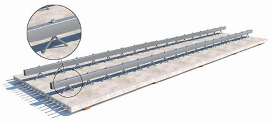
Figure 1.
A 3D graph of a precast prestressed concrete slab with removable rectangular steel-tube lattice girders.
3. Structural Arrangement
The prestressed concrete composite slab with removable rectangular steel-tube lattice girders (hereafter referred to as a CDB composite slab) has a removable rectangular steel-tube bracket which primarily consists of upper-chord rectangular steel tubes, web reinforcement bars, and connecting bolts. Before the prefabricated bottom plates were poured, the bolt holes in the web reinforcement were then aligned with the bolt holes in the steel tubes, and the bolts were quickly installed and tightened. These steel tube brackets were then lifted at the corresponding position of the bottom plate, and the lifting height was adjusted so that the bottom of the web reinforcement is 25 cm deep into the bottom plate, and then they were waited for the pouring.
Depending on the span, two types of supports are used: planar steel-tube brackets and spatial steel-tube brackets, as shown in Table 1, and its structural schematic diagram is shown in Figure 2.

Table 1.
Form of steel lattice girders.
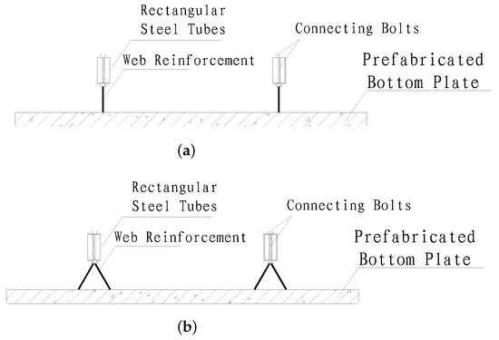
Figure 2.
Lattice girders with removable rectangular steel tubes: (a) planar steel-tube brackets; (b) spatial steel-tube brackets.
The CDB composite slab adopts a 40 mm thick prefabricated bottom plate, with 6 mm diameter distribution rebars arranged along the width of the plate, and 5 mm or 7 mm diameter prestressed steel arranged according to the span along the length of the plate. The use of removable rectangular steel tubes enhances the rigidity and crack resistance of the prefabricated bottom plate during construction. Since the web reinforcement bars connect the upper-chord rectangular steel tubes with the bottom-plate concrete, they primarily transmit forces and provide some shear resistance after composite action, but they have little effect on the bending capacity of the composite slab [12]. Therefore, for CDB prefabricated bottom plates with a span of not more than 6.3 m, the number of web reinforcement bars is reduced, and the lower-chord rebars are removed, using planar steel tube brackets. For large-span CDB prefabricated bottom plates exceeding 6.3 m, spatial steel-tube brackets are used. The upper-chord rectangular steel tubes are connected to the web reinforcement bars with bolts. The composite-layer concrete is poured up to the lower surface of the rectangular steel tubes, and the upper-chord rectangular steel tubes can be removed only after the composite layer concrete strength reaches 100% of the cubic compressive strength, followed by concrete filling and flattening of the bolt holes on the lower surface of the rectangular steel tubes. Due to the short time from production to on-site pouring of concrete for the prefabricated bottom plate and the use of galvanized process for the upper chord rectangular steel tubes, there is no reduction in effective cross-sectional area due to rust.
4. Static Test Program
4.1. Specimen Design and Fabrication
In accordance with the “Technical Code for Precast Concrete Structures” JGJ 1-2014 [13], the experiment was designed to include three prefabricated bottom plates and one composite slab. The parameters of each specimen are presented in Table 2. The arrangement of the reinforcement bars in the prefabricated bottom plates, exemplifying a span of 4800 mm and a width of 1200 mm, is shown in Figure 3.
Table 2.
Parameters of specimens.
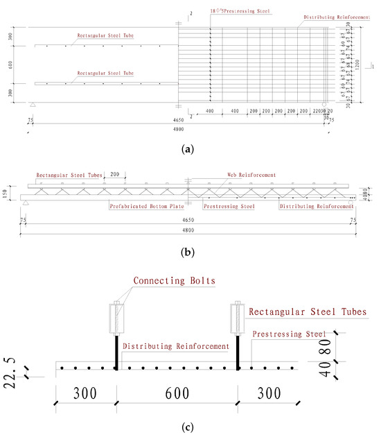
Figure 3.
Dimensions and details of 4800 mm specimens: (a) plane reinforcement diagram of prefabricated bottom plate; (b) 1-1cross-section drawn; (c) 2-2 cross-section drawn.
The specimens CDBP4812 and CHBP4812, with a size of 4800 mm × 1200 mm, include a 40 mm prefabricated bottom plate and an 80 mm composite layer; the specimens CDBP9012 and CDBK9012, with a size of 9000 mm × 1200 mm, include a 40 mm prefabricated bottom plate and a 210 mm composite layer. The prefabricated bottom plate’s transverse distribution reinforcement uses 6 mm diameter HPB300 bars; in order to prevent excessive shear at the ends of the plates, at least three densified rebars of the same specification are arranged within 100 mm of the plate ends. The prestressing steel of the test specimen adopts spiral-ribbed prestressing steel wire, with a controlled tensile stress of 0.6 fptk. The bottom plate uses C40 concrete, and the composite layer uses C30 concrete.
Two removable rectangular steel tube brackets are set on the upper part of each prefabricated bottom plate at a distance of 600 mm, using Q235B steel measuring 60 mm × 40 mm × 3 mm. The prefabricated bottom plates CDBP4812 and CDBP9012 use HPB300 reinforcement bars with diameters of 10 mm and 14 mm in the web, respectively, forming planar steel-tube brackets with the upper chord rectangular steel tubes; CDBK9012 uses 14 mm diameter HPB300 bars in the web, forming a spatial steel-tube bracket with the upper-chord tubes. The upper-chord rectangular steel tubes and the web reinforcement bars are connected by 4.8 grade bolts, and the distance between adjacent bending points of the web reinforcement bars is 200 mm. The centers of the upper-chord rectangular steel tubes of the prefabricated bottom plate with spans of 4800 mm and 9000 mm are 150 mm and 280 mm away from the bottom edge of the plate, respectively.
The platform is cleaned before the fabrication of specimens. Then, according to the design requirements to lay a height of 40 mm for the vertical steel mold, which was continuously laid on the pre-tensioning bed, the center interval was a 100 mm wide gap. To prevent the specimens from being difficult to release, the steel mold was sprayed with mold release agent and dried immediately after laying. Prestressing steel was laid while the release agent was drying, and the prestressing steel was tensioned using automatic screw tensioners to achieve the designed prestressing values. In the process of binding the steel-tube brackets, pads with a height of 20 mm were placed under the prestressing steel wire to ensure the thickness of the protective layer of the prestressing steel. Strain gauges were affixed in designated positions according to the experimental plan before casting the concrete, and the leads were extended outside the mold. The top surface of the bottom plate was kept naturally rough after the concrete was cast. During the casting process of both the bottom plate and the composite layer, test blocks were reserved and cured under the same conditions as the specimens. After the concrete strength of the bottom plates reached 75% of the design strength, the prestressing steel was released, and the concrete continued to be cured.
4.2. Mechanical Properties of Concrete and Steel
Prior to the commencement of the experiments, tests were conducted to assess the actual strength of the reserved concrete cubic specimens, rebar, and steel materials. The results of are presented in Table 3 and Table 4, respectively.
Table 3.
The conversion results of concrete strength.
Table 4.
The conversion results of steel strength.
4.3. Loading Program
The original purpose of this experiment was to test whether the mechanical properties of the prestressed concrete composite slab with removable rectangular steel-tube lattice girders meet the requirements of mechanical properties that can be lifted and transported during the construction process and poured into floor slabs. The experiment was selected based on a thorough review of the specifications and the papers for the static bending experiment of these plates. For this reason, the static bending experiment was designed with reference to previous static tests and with the resources available in the laboratory. The ‘Code of Practice for Quality Acceptance of Concrete Structural Engineering Construction’ [14] identifies this loading method as the most effective for demonstrating the mechanical properties of these slabs.
The experiment employed uniformly distributed static loading on concrete blocks, each weighing 90 kg. To avoid stress concentration on the rectangular steel tubes by the load blocks, they were distributed at specific intervals. When the height of the stacked load blocks exceeded that of the upper-chord rectangular steel tubes, the load blocks were arranged evenly. During the experiment, specimens CDBP4812, CHBP4812, CDBP9012, and CDBK9012 were simply supported at both ends, while CDBP9012 and CDBK9012 had an additional support added at the mid-span. In order to avoid stress concentration at the supports, padding was added above and below the rollers, and fine sand was placed between the rollers and padding to ensure uniform and secure contact. The length of both ends of the rest was 75 mm [15].
Before loading, the specimens underwent preloading, with each load level being 20% of the cracking load and each load level maintained for 15 min. This phase primarily checked the stability of the supports and ensured that the instruments and loading equipment were in a normal condition, including zeroing the instruments. After preloading, formal loading commenced. For specimen CDBP4812, each load level was 0.61 ; for specimens CDBP9012 and CDBK90129, each load level was 0.65 .
According to the “Standard for Test Methods of Concrete Structures” GB/T 50152-2012 [16] and considering the structural features of the CDB prefabricated bottom plates, loading was ceased when specimens exhibited any of the following indicators, which are deemed to have reached the limit of their bearing capacity: the width of cracks at the location of the main tension reinforcement reached 1.50 mm; breakage of the tension reinforcement in the specimens; the bending deflection reached 1/50 of the span; the bending or instability of the steel tube supports; and the crushing of concrete in the compression zone of the specimens.
4.4. Measurement Point Arrangement
The arrangement of displacement and strain measurement points for specimens CDBP4812 and CHBP4812 is shown in Figure 4. The arrangement for specimens CDBP9012 and CDBK9012 is shown in Figure 5.
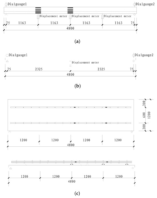
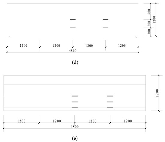
Figure 4.
Displacement and strain measuring points of CDBP4812 and CHBP4812: (a) displacement and plate side strain measurement points of CHBP4812; (b) displacement measurement points of CDBP4812; (c) strain measurement points of rectangular steel tubes and web reinforcement bars of CDBP4812; (d) strain measurement points of bottom of plates; (e) strain measurement points of prestressing steel.
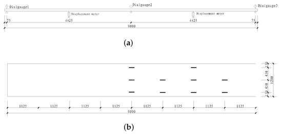
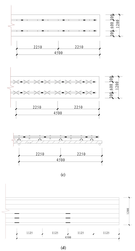
Figure 5.
Displacement and strain measuring points of CDBP9012 and CDBK9012: (a) displacement measurement points of CDBP9012 and CDBK9012; (b) strain measurement points of bottom plates; (c) strain measurement points of rectangular steel tubes and web reinforcement bars; (d) strain measurement points of prestressing steel.
4.5. Experimental Phenomena
4.5.1. Prefabricated Bottom-Plate Specimens
For the prefabricated specimen CDBP4812, the initial reverse camber was 15 mm. When the external load reached 2.45 , the reverse camber basically disappeared, and the bottom plate was laid down in a horizontal position. Prior to the load reaching 6.13 , no visible cracks appeared in the concrete at the bottom of the plate. The deflection increased slowly with each level of loading, and the change in rigidity was not obvious. When the load was increased to 6.74 , four through-cracks with a width of 0.2 mm uniformly appeared in the midspan of the underside of the bottom plate, extending upward along the side of the plate to 1/3–2/3 of its height. When the load was increased to 10.42 , the number of bottom cracks increased, with the cracks extending upward along the side of the bottom plate to 1/2–3/4 of its height. Punching shear failure occurred between the B-side web reinforcement bar and the concrete, and the upper-chord rectangular steel tubes buckled (Figure 6a,b), leading to the cessation of loading. The distribution of cracks at the bottom of specimen CDBP4812 is shown in Figure 7. During the loading process, no brittle fracture occurred in the prestressing steel, and there was no out-of-plane instability in the upper-chord rectangular steel tubes or the web reinforcement bars.
Figure 6.
Failure characteristics of specimen CDBP4812: (a) buckling damage at upper chord of rectangular steel tubes of specimen CDBP4812; (b) damage caused by punching shear of specimen CDBP4812.
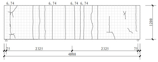
Figure 7.
Distribution of cracks at the bottom of specimen CDBP4812.
For specimen CDBP9012, the initial reverse camber was 8 mm. When the external load reached 1.96 , the reverse bow basically disappeared, and the bottom plate became horizontal. Prior to the load reaching 4.58 , no visible cracks appeared in the concrete at the bottom of the plate, the deflection increased little at each loading level, and the change in rigidity was not obvious. When the load was applied to 5.23 , a through-crack with a width of 0.1 mm appeared on the underside of the base plate, extending upward along the side of the plate to 1/3–2/3 of its height. When the load was increased to 8.50 , multiple through-cracks appeared at the bottom of the plate, with the cracks extending upward to 1/2–3/4 of the plate’s height. Delamination damage occurred in the reinforcement of the web reinforcement bars on the A-side (Figure 8a,b), leading to the cessation of loading. The distribution of cracks at the bottom of specimen CDBP9012 is shown in Figure 9. During the loading process, no brittle fracture occurred in the prestressing steel, and there was no out-of-plane instability in the upper chord rectangular steel tubes or the web reinforcement bars.
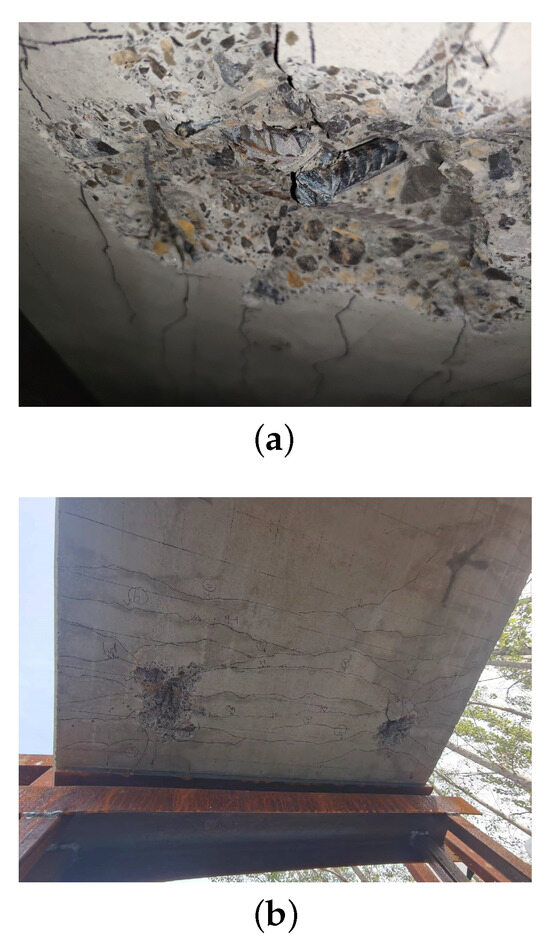
Figure 8.
Failure characteristics of specimen CDBP9012: (a) delamination damage of web bars of specimen CDBP9012; (b) damage done by punching shear of specimen CDBP9012.
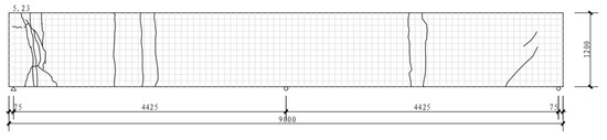
Figure 9.
Distribution of cracks at the bottom of specimen CDBP9012.
For specimen CDBK9012, the initial reverse camber was 53 mm. When the external load reached 4.58 , the reverse camber basically disappeared, and the bottom plate became horizontal. When the load was applied to 11.11 , a through-crack with a width of 0.1 mm appeared on the upper surface of the middle support of the specimen (Figure 10a). When the load was increased to 13.73 , two through-cracks appeared on the underside of the specimen, extending upward along the side of the base plate to 1/2–3/4 of its height. When the load increased to 17.32 , multiple through-cracks appeared at the bottom of the plate, with the cracks extending upward to 1/2–3/4 of the plate’s height, and the web reinforcement bars buckled (Figure 10b), leading to the cessation of loading. The distribution of cracks at the bottom of specimen CDBK9012 is shown in Figure 11. During the loading process, no brittle fracture occurred in the prestressing steel, and there was no out-of-plane instability in the upper chord rectangular steel tubes or the web reinforcement bars.
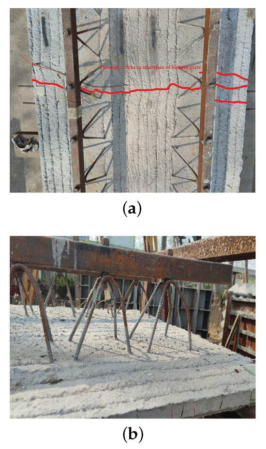
Figure 10.
Failure characteristics of specimen CDBK9012: (a) upper surface crack at span middle of specimen CDBK9012; (b) web buckling of specimen CDBK9012.
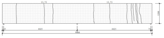
Figure 11.
Distribution of cracks at the bottom of specimen CDBK9012.
The two specimens, CDBP9012 and CDBK9012, have the same dimensions, but the crack distributions are different due to their different structural failure conditions. As mentioned above, the end of loading of sample CDBP9012 was signaled by the delamination damage of the web reinforcement on the A side. During the loading process, the weld joint connecting the web reinforcement to the A side of the bottom plate became loose, resulting in reduced rigidity and the appearance of cracks in the center of the A side. Upon completion of the loading process, the weld joint that connected the web reinforcement on side A of the bottom plate fractured, the rigidity of side A of the bottom plate was drastically reduced, and the concrete in the area of side A crumbled. So the crack distribution clearly indicates that the cracks are predominantly concentrated on side A (the left side). The end of the loading of sample CDBK9012 was signaled by the flexure of the web reinforcement on the B side. During the loading process, no structural fracture yielding occurred, and the rigidity of the whole structure remained almost unchanged, and the cracks were normally distributed on the plate. Upon completion of the loading process, the web reinforcement on the B side (right side) of the bottom plate buckled, which reduced the rigidity of that side and caused cracks to concentrate there.
4.5.2. Composite Slab Specimens
For specimen CHBP4812, the upper-chord rectangular steel tubes were removed when the strength of the composite-layer concrete reached 100%. When the load was increased to 5.51 , six through-cracks appeared at the midspan of the plate bottom, with a width of up to 0.15 mm. As loading progressed, the number of cracks increased, becoming deeper and wider. The through-cracks extended upward along the side of the plate to the junction between the bottom plate and the composite layer, with some cracks continuing to extend into the upper part of the composite layer after extending along the junction by 2–6 cm (Figure 12a). The distribution of cracks at the bottom of specimen CHBP4812 is shown in Figure 13. During the loading process, no brittle fractures occurred in the prestressing steel.
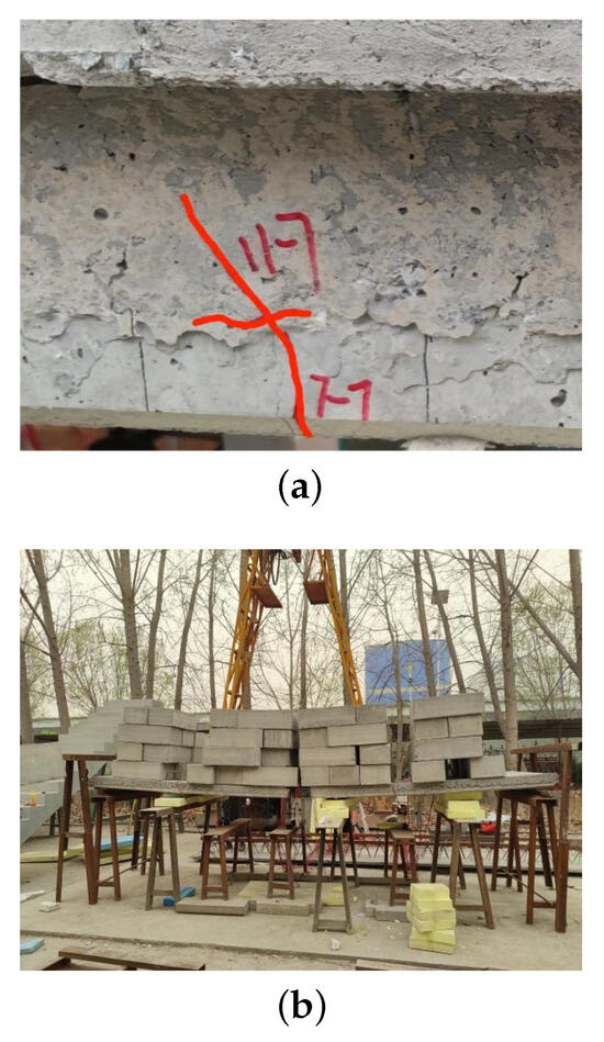
Figure 12.
Failure characteristics of specimen CHBP4812: (a) side cracks of specimen CHBP4812; (b) specimen CHBP4812’s deflection exceeds the limit.
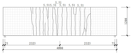
Figure 13.
Distribution of cracks at the bottom of specimen CHBP4812.
5. Results
5.1. Load-Displacement Curve
5.1.1. Prefabricated Bottom-Plate Specimens
The load-displacement curves for the three precast bottom-plate specimens are shown in Figure 14. Prior to cracking, the load-displacement relationship of the precast bottom-plate specimens was essentially linear, indicating that the specimens were in the elastic phase [17]. This phase extended from the initial loading until cracking of the concrete took place at the bottom of the plates, along with each increase in load, there is a slight decrease in rigidity and nearly identical displacements. The curves for specimens CDBP9012 and CDBK9012 demonstrate that the spatial web rebar steel tubes can provide sufficient supports in large-span precast bottom plates. In other words, these tubes can effectively enhance their resistance to tensile and punching shear forces, which then ensures the flexural rigidity, crack resistance, and load-bearing capacity of the precast bottom plates at a high level. After cracking happened, the specimens entered the elasto-plastic phase, where the slope of the load-displacement curve significantly decreased, indicating that the rigidity rapidly deteriorated, and the rate of displacement accelerated [18]. These results have shown that cracking prevention of the bottom plate is a prerequisite for CDB composite plates to achieve the span with no or minimal support across various span ranges.
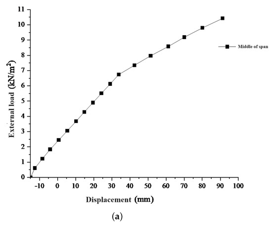
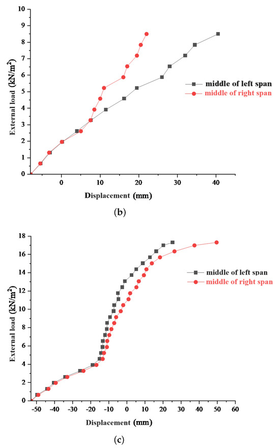
Figure 14.
Loading-displacement curves of prefabricated bottom–plate specimens: (a) load–displacement curve of specimen CDBP4812; (b) load–displacement curve of specimen CDBP9012; (c) load–displacement curve of specimen CDBK9012.
The load-displacement curve of six concrete composite slabs with steel lattice girders is displayed in Figure 15 [6]. Basic information of the load-displacement curve of six concrete composite slabs with steel lattice girders is shown in Table 5. These slabs are similar in size to CDBP4812, enabling a direct and accurate comparison. First of all, comparing the maximum load bearing capacity, CDBP4812 has a maximum load bearing capacity of 10.42 , which is significantly higher than GGDB2’s capacity of 5.56 . Second, comparing the displacements, it is evident that the maximum displacement of CDBP4812 is similar to that of GGDB1 and GGDB2. Finally, comparing the slopes, the loading/displacement values of CDBP4812 are significantly higher than any of the concrete composite slabs with steel lattice girders in Figure 15, and therefore, the rigidity properties of CDBP4812 are higher than these slabs. In terms of a parametric comparison, CDBP4812 has a high load bearing capacity and rigidity, and its mechanical properties can surpass those of the majority of concrete composite slabs used in current engineering applications.
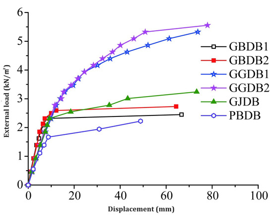
Figure 15.
The load-displacement curve of six concrete composite slabs with steel lattice girders [6].
Table 5.
Basic information of the load-displacement curve of six concrete composite slabs with steel lattice girders.
The cracking load and cracking deflection of the prefabricated bottom-plate specimens are shown in Table 6. According to Table 6, the use of removable steel–tube lattice girders for prefabricated base plates not only effectively improves flexural rigidity and load-bearing capacity but also significantly reduces the need for bottom supports, which saves steel approximately 24% [5], as compared to conventional composite plates. For specimen CDBP9012, the insufficient application of pre-stress during the tensioning of the prestressing steel resulted in a cracking load significantly lower than the construction load. Small-span prefabricated bottom plates utilizing planar steel-tube lattice girders still maintain good rigidity, stability, and load-bearing capacity despite the reduced usage of web reinforcement bars.
Table 6.
Cracking loadings and deflections of prefabricated bottom-plate specimens.
In Table 6, there is a negative value of 4.674. That is, “The final deflection of specimen CDBK9012 at the end of loading is −4.674 mm, in other words, it is 4.674 mm upward reverse camber”. This occurred because of the large initial reverse camber of specimen CDBK9012. The mid-span support significantly increases the vertical rigidity of the bottom plate and reduces deflection due to external loads. This resulted in the fact that when the loaded load yielded the web reinforcement on the B side of specimen CDBK9012, the reverse camber on the A side was not eliminated, and a reverse camber of 4.674 mm remained. The excessive prestress design caused the large reverse camber. The control of the prestress degree will not be discussed further in this text but will be thoroughly examined in future studies.
5.1.2. Composite Slab Specimens
The load–displacement of the composite plate specimens is shown in Figure 16. There are obvious elastic and elasto-plastic phases in the loading process of the composite plate specimens [17,18]. Table 7 presents the cracking load and deflection of the CDB composite plate specimens. The maximum unsupported span of these composite plate specimens can reach up to 4.8 m, which is larger than the support spacing for typical composite plates. This effectively reduces the number of supports while achieving a cracking load greater than 3.5 and deflection less than l/200, meeting the design requirements for general office and residential buildings [19].
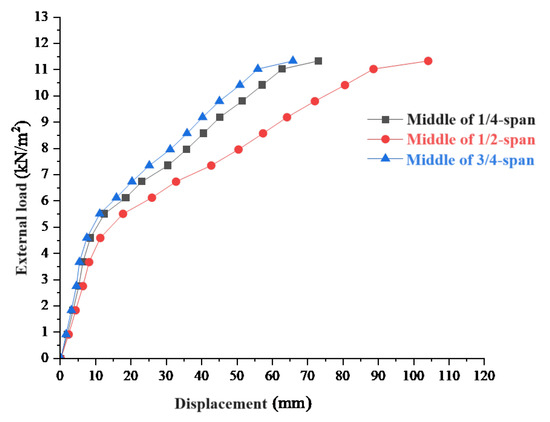
Figure 16.
Loading–displacement curves of composite slab specimens.
Table 7.
Cracking loadings and deflections of composite slab specimens.
5.2. Load–Strain Relationship of Concrete
The strain variation curves of concrete at the top and bottom of the span middle for each prefabricated bottom-plate specimen are shown in Figure 17. Prior to cracking, the strain curve of the concrete is approximately linear, indicating that the concrete is in an elastic phase. After cracking, the slope of the concrete strain curve decreases, and the increase in concrete strain is greater than the increase in load, indicating that the concrete is in an elasto-plastic phase. Comparing CDBP9012 and CDBK9012, the strain variation curve of CDBK9012 is significantly better than that of CDBP9012.
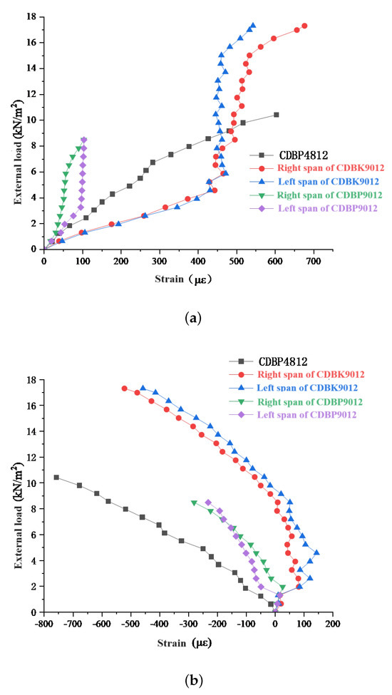
Figure 17.
Loading–concrete strain curves of prefabricated bottom-plate specimens: (a) loading-concrete strain curves of bottom surfaces of the bottom plates; (b) loading-concrete strain curves of top surfaces of the bottom plates.
The variation curves of concrete strain at the span middle slab side of the composite slab specimens are shown in Figure 18. The horizontal axis represents the longitudinal strain of the concrete at each measuring point across the section, while the vertical axis represents the section height, with 0 mm indicating the bottom of the plate and 120 mm indicating the top of the plate. It can be observed that during the elastic phase, the strain of the concrete along the side of the plate distributes linearly with the section height, indicating that the composite plate’s stress conforms to the assumption of plane sections [6,17].
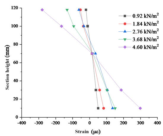
Figure 18.
Variation curves of concrete strain at the span middle slab side of CHBP4812.
The strain variation curves on the top and lower surfaces of the rectangular steel tubes at the span middle of the prefabricated bottom plates are shown in Figure 19. From Figure 19, it is evident that in the elastic phase, the strain on the top and lower surfaces of the rectangular steel tubes changes linearly with the increase in load. After the bottom plate cracks, some of the concrete ceases to function, and the stress transfer is undertaken by the upper chord rectangular steel tubes. As the load increases, the strain curve gradually flattens, the rate of strain change accelerates, and the stress distribution in the specimen is redistributed. Notably, for the CDBP4812 specimen towards the end of loading, local buckling occurs in the rectangular steel tubes, with a relatively significant change in strain observed. The upper-chord rectangular steel tubes provide sufficient longitudinal rigidity during the loading process.
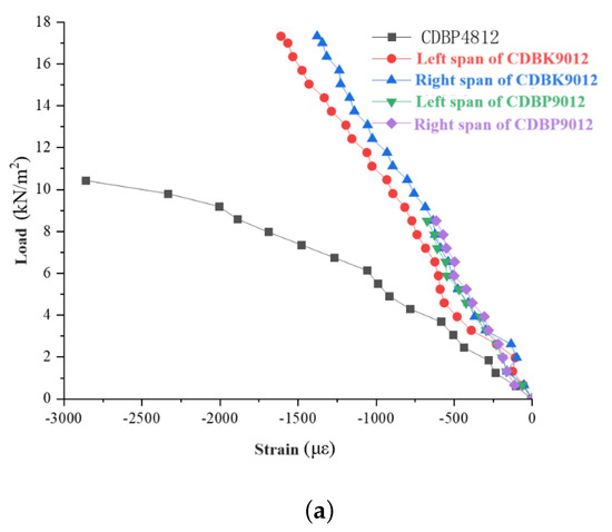
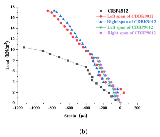
Figure 19.
Loading–steel strain curves of steel tube: (a) top surface of steel tube; (b) lower surface of steel tube.
The strain variation curves of the web reinforcement bars at the edge, 1/4 span, and 1/2 span positions of the prefabricated bottom-plate specimens are shown in Figure 20. The strain variation curves of the web reinforcement bars in the other specimens are similar to those in the CDBK9012 specimen, which is used here as an example. It demonstrates that the web reinforcement bars exhibit an alternating distribution of tension and compression and did not yield under construction loads. The web reinforcement bars connect the upper-chord rectangular steel tubes to the bottom-plate concrete and provide certain lateral rigidity, with no instability observed during the experiment.
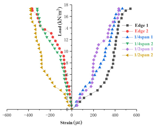
Figure 20.
Loading-web strain curves of CDBK9012.
6. Conclusions
In this paper, researchers propose a new type of prestressed concrete composite slab with removable rectangular steel-tube lattice girders, whose bottom plate consists of a temporary structure composed of prestressed concrete prefabricated plates and removable rectangular steel-tube frames. Researchers fabricated three different prestressed concrete bottom plates and prestressed concrete composite slabs and conducted static load tests on these four experimental samples. The analysis of the results led to the following conclusions:
- (1)
- The upper-chord rectangular steel tubes, connected to the bottom-plate concrete by the web reinforcing bars, work together effectively, enhancing the bending rigidity, crack resistance, and load-bearing capacity during the construction phase. This significantly reduces the number of supports needed, with a maximum unsupported span of up to 4.8 m, and provides a certain safety reserve.
- (2)
- The CDB composite slabs, utilizing removable upper-chord rectangular steel tubes, are characterized by their ease of installation, convenience in disassembly, and reusability. Compared to composite slabs of the same size, the steel usage is reduced by about 24%, with larger spans yielding more significant economic benefits, demonstrating good economic performance. Mechanical properties of the CDB composite slabs can surpass those of the majority of concrete composite slabs used in current engineering applications.
- (3)
- After the post-cast composite layer concrete reaches the specified strength and the upper-chord rectangular steel pipes are removed, the cracking load of the composite slab still exceeds 3.5 , and the deflection is less than l/200, meeting the design requirements for general office and residential buildings. Moreover, the cooperative work between the upper and lower layers is effective, consistent with the assumption of a plane section.
- (4)
- The CDB composite slabs exhibit reverse cambering before loading. To fully leverage the mechanical properties of the CDB composite slabs, subsequent research could focus on this aspect, discussing how to determine the magnitude of prestress under different loading conditions.
Author Contributions
Investigation, J.L. and S.S.; Writing—original draft, G.B. and H.J.; Writing—review and editing, J.L. and S.S.; Visualization, X.L. All authors have read and agreed to the published version of the manuscript.
Funding
This research received no external funding.
Data Availability Statement
Data are contained within the article.
Conflicts of Interest
The authors declare no conflicts of interest.
References
- Zhang, J.S.; Nie, H.H.; Yang, Y.L.; Yao, Y. Research and application of pre-stressed concrete composite slabs. Appl. Mech. Mater. 2012, 166, 131–139. [Google Scholar] [CrossRef]
- Lee, Y.J.; Kim, H.G.; Kim, M.J.; Kim, D.H.; Kim, K.H. Shear performance for prestressed concrete hollow core slabs. Appl. Sci. 2020, 10, 1636. [Google Scholar] [CrossRef]
- Zhang, J.; Yao, Y.; Zhou, X.; Yang, Y.; Wang, Y. Failure mode and ultimate bearing capacity of precast ribbed panels used for concrete composite slabs. Adv. Struct. Eng. 2013, 16, 2005–2017. [Google Scholar] [CrossRef]
- Nasser, G.D.; Tadros, M.; Sevenker, A.; Nasser, D. The legacy and future of an American icon: The precast, prestressed concrete double tee. PCI J. 2015, 60, 49–68. [Google Scholar] [CrossRef]
- Kurobane, Y.; Ogawa, K.; Sakae, K. Behavior and design of composite lattice girders with concrete slabs. In Tubular Structures; Routledge: London, UK, 2021; pp. 69–76. [Google Scholar]
- Liu, W.; Cui, S.; Liu, C.; Shi, L. Experimental and theoretical study on bending behavior of prestressed concrete composite slabs with steel trusses. J. Build. Struct. 2021, 42, 95–106. [Google Scholar]
- liu, B. Experimental and Numerical Study of Concrete Composite Hollow Core Slab with Precast Prestressed Concrete Ribbed Panel. Ph.D. Thesis, Hunan University, Changsha, China, 2016. [Google Scholar]
- Zhao, G.; Zhao, L.; Li, W.; Zhang, X.; Wang, X. Experimental and design key problems study on bending behavior of prestressed concrete composite slab with concrete rib. Jianzhu Jiegou Xuebao/J. Build. Struct. 2023, 44, 171–182. [Google Scholar]
- Wang, X.; Na, Z.; Zhao, G.; Han, W. Progress in structural performance research and engineering application of prestressed concrete double T plates. Ind. Constr. 2023, 53, 12–20. [Google Scholar] [CrossRef]
- Shen, P.; Liang, X. Design of Concrete Structures; Higher Education Press: Beijing, China, 2007; pp. 75–85. [Google Scholar]
- Wenzheng, L.; Shiqi, C. Experimental study and parametric analysis on flexural properties of bilateral prestressed composite concrete slabs with steel trusses. Ind. Constr. 2021, 51, 32–39+31. [Google Scholar] [CrossRef]
- Huizu, Z.; Shizhong, L.; Zhilong, C. Stress analysis for a post-tensioned thin precast slab with removable truss of steel bars. Build. Struct. 2021, 51, 1187–1191. [Google Scholar]
- JGJ 1-2014; Technical Specification for Precast Concrete Structures. Chinese Standards: Beijing, China, 2014; p. 24.
- Li, D. Code of Practice for Quality Acceptance of Concrete Structural Engineering Construction; General Administration of Quality Supervision, Inspection and Quarantine of China: Bejing, China, 2015. [Google Scholar]
- Shun, W. Study on Mechanical Behaviors of Prestressed Concrete Composite Slab with Grouted-Round-Steel Tube Truss. Ph.D. Thesis, Shandong Jianzhu University, Jinan, China, 2019. [Google Scholar]
- GB/T 50152-2012; Standard for Test Method of Concrete Structures. China Architecture and Building Press: Beijing, China, 2012.
- Cheng, X.; Zejin, S.; Changcheng, W.; Zhongyi, Z. Stress Field Simulation Based on Log Curves and the Theory of Elastic Thin Plate. J. Southwest Pet. Univ. (Sci. Technol. Ed.) 2015, 37, 76. [Google Scholar]
- Chepurnenko, A.; Saibel, A.; Yazyev, B. Determination of the Breaking Load for Concrete Slabs Based on the Deformation Theory of Plasticity. Procedia Eng. 2016, 150, 1694–1700. [Google Scholar] [CrossRef][Green Version]
- Hetao, H.; Mingyuan, F.; Canxing, Q. Experimental and theoretical study on flexural behavior of prestressed concrete composite slab with steel rib. J. Build. Struct. 2018, 39, 103–110. [Google Scholar]


Disclaimer/Publisher’s Note: The statements, opinions and data contained in all publications are solely those of the individual author(s) and contributor(s) and not of MDPI and/or the editor(s). MDPI and/or the editor(s) disclaim responsibility for any injury to people or property resulting from any ideas, methods, instructions or products referred to in the content. |
© 2024 by the authors. Licensee MDPI, Basel, Switzerland. This article is an open access article distributed under the terms and conditions of the Creative Commons Attribution (CC BY) license (https://creativecommons.org/licenses/by/4.0/).