Abstract
An ordinary double steel plate–concrete composite wall (ODSC wall) is composed of core concrete, the faceplates, and shear connectors such as studs, etc. Based on an ODSC wall, a new type of stiffened double steel plate–concrete composite wall (SDSC wall) is conceived by incorporating additional stiffeners and tie plates on the internal surface, which aims to improve the local stability of the faceplates. In the authors’ previous study, a series of axial compression tests were conducted on the SDSC walls. The SDSC walls in the test showed better mechanical performance, as the presence of stiffeners changed the buckling deformation mode and significantly improved the corresponding local buckling stress and ultimate strength. In this paper, a comprehensive summary of the prior research on SDSC walls is provided, and the effect of the constructive parameters on the local stability is discussed. The results reveal that the modified formula of the critical stress can degrade to the Euler formula when the stiffener-to-stud spacing ratio (i.e., a/B ratio) approaches infinity. What is more, the analysis model is also applicable for DSC walls with enclosed side plates, and the proposed formula can predict the buckling stress of the SDSC walls with different a/B ratios. In addition, according to the analysis of the numerical simulation, a design approach for SDSC walls to prevent local buckling is provided, which is applicable in practical engineering applications.
1. Introduction
The double steel plate–concrete (DSC) composite structure mainly consists of outer faceplates, inner filled concrete, and connectors, as shown in Figure 1. The entire faceplate replaces the traditional load-bearing steel bars that are dispersed in concrete and can withstand the in-plane tensile and compressive stresses. The filled core concrete bears the main pressure and can provide unilateral constraint for the faceplate, thereby improving the local stability of the DSC structures [1]. The connectors between the outer faceplates and the core concrete can transfer the shear force at the interface and play a role in resisting pull-out [2]. In addition, the existence of the outer faceplates can not only effectively alleviate the problems of concrete cracking and steel corrosion, it can also be used as a permanent formwork, which is convenient for modular construction. In this scenario, the DSC composite structure has been widely used in ultra-high-rise buildings [3], immersed tube tunnels [4], nuclear power engineering [5], and harbor projects [6], as shown in Figure 2. Although the DSC composite structure possesses a lot of merits, it should be noted that some deficiencies can be found in its practical application. One of the major deficiencies is the local buckling of the faceplates, as the out-of-plane deformation of the steel plate between the two rows of connectors cannot be restrained by the inner in-filled concrete. As a consequence, local buckling will occur once the compressive stress of the faceplate reaches the critical buckling stress and then diminish the bearing capacity of the DSC structure.
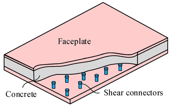
Figure 1.
Basic composition of ordinary DCS structures.
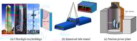
Figure 2.
Applications of DCS structures.
To avoid the detrimental effect of buckling on the structural performance and to effectively utilize the materials, several experimental studies have been carried out to study the local buckling in DSC structures. In 1990, based on the energy method, Davies et al. [7] derived a formula for calculating the local buckling stress of a steel plate, considering a relatively weak constraint on one side. The research findings show that the critical buckling stress of the plate can be obtained by the Euler formula, which treats the plate as a column, with one edge simply supported and the other edge fixed and taking the effective length factor K to equal 0.7. In 1991, Wright et al. [8,9,10] carried out an axial compression test focused on DSC walls with bolted connectors and derived a buckling stress formula for steel plates based on the principle of virtual work. In 1995, Uy et al. [11,12] carried out an experimental and theoretical study on the stability of the profiled steel plates in DSC structures. The critical buckling stress of the profiled steel plate under varied boundary conditions was obtained by the finite strip method. In 1996, Roberts et al. [13] carried out an experimental study on DSC slabs with long studs. The research findings show that the critical buckling stress of the plate can be obtained by treating the plate as a column with two fixed edges and taking the effective length factor K to equal 0.5 in the Euler formula. In 2013, Yang Yue et al. [14] completed a series of axial compression tests on DSC walls with a B/t ratio (the ratio between the stud spacing and the steel plate thickness) ranging from 37.5 to 75. It was found in the research that the critical buckling stress of the plate can be obtained by treating the plate as a column with two edges that are simply supported and taking the effective length factor K to equal 1.0 in the Euler formula. In 2014, Zhang et al. [15] performed finite element simulations and carried out relevant parametric analyses on the DSC structures in the literature [16] and gave suggestions on the buckling behavior and the value of the critical B/t ratio of the steel plates. In 2019, Yan et al. [17,18] created a new DSC wall with J-hook connectors and proposed a formula for calculating the critical stress, in which the effective length factor K was suggested to take the value of 0.825.
Although the above studies have proposed a variety of formulas, all of them improve the local stability by encrypting connectors, which cannot truly change the buckling modes of the plate between the adjacent rows of connectors. Consequently, a thoroughly buckling strip can also lead to rapid overall instability, which seriously deteriorates the mechanical performance. To improve the mechanical performance of the ODSC walls, the longitudinal stiffeners and tie plates were proposed to be incorporated at the inner faceplates by the authors [19,20], as shown in Figure 3. Furthermore, based on ODSC walls, a new type of SDSC walls with longitudinal stiffeners is proposed by the authors, as shown in Figure 4. The research findings indicate that the presence of stiffeners and tie plates changes the buckling mode, as demonstrated in Figure 5. The strip buckling mode was transformed into an element buckling mode. In this condition, the local buckling will be delayed or even avoided. Furthermore, as the presence of the post-buckling strength of the faceplates, the ultimate strength of the SDSC wall will be clearly improved.
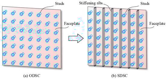
Figure 3.
Basic composition of SDCS structures.
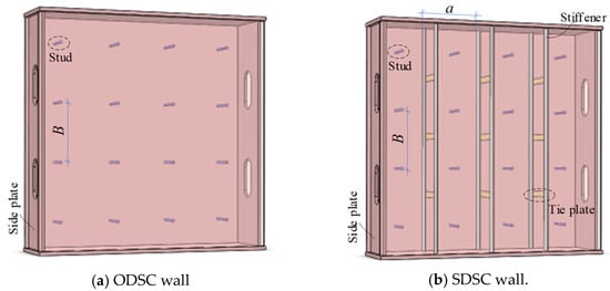
Figure 4.
Schematic diagram of two DSC walls.
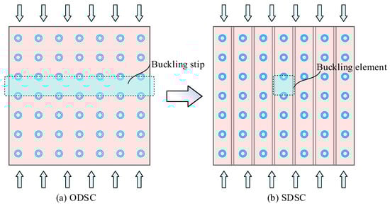
Figure 5.
Buckling modes of two DCS structures.
It is worth mentioning that the above measure has been shown in the literature [19,20] to significantly improve the stability of the surface steel plate, and the corresponding analytical method in the literature can also provide a more accurate estimation for the buckling stress of the faceplate, which is a good guide for the selection of the distance-to-thickness ratio. However, some aspects of previous studies are still in need of further research: (1) The degradation of the stiffened buckling model needs to be researched. When the stiffener-to-stud spacing ratio (i.e., geometric parameter, a/B ratio) approaches infinity, the analytical model should be approximately degraded to the traditional Euler column model. (2) The sample of the test is relatively small, and the authors only discussed the case of the a/B ratio equaling 1 and 2. When varying the a/B ratios, it is necessary to study whether the modified formula is still applicable. (3) Although the design suggestions for the critical B/t ratio were given, the design suggestions for other key parameters such as the geometric dimensions of studs, stiffeners, and tie plates were not given, which means that the proposed method cannot directly guide the structural design.
To offer a comprehensive design method that is applicable to practical scenarios for SDSC structures, this paper delves into the comparison between the Euler formula and a modified theoretical formula, discussing its degradation characteristics. Furthermore, the paper validates the efficacy and precision of the modified formula across various a/B ratios by referencing prior experimental data and finite element analyses. Moreover, recommendations regarding geometric parameters such as studs, stiffeners, and tie plates are suggested based on numerical simulations. Ultimately, a comprehensive design methodology for SDSC walls is outlined.
2. Degradation of the Modified Model
A substantial body of experimental programs have been conducted to explore the buckling behavior of ODSC walls, and it is concluded that the ratio of stud spacing to faceplate thickness (B/t ratio) is a critical parameter affecting the buckling stability of the faceplates. However, for the SDCS walls, because the arrangement of the connectors has changed, the buckling mode of the faceplate has changed as well. So, in the authors’ previous study [19,20], the constraint effect of the stiffeners was considered in the modified model, and a bidirectional compression formula (Equations (1) and (2)) was proposed to predict the local buckling stress. It should be noted that the buckling stress (i.e., σcr) of the SDSC walls is a function of the B/t and a/B (shape parameter, the ratio of stiffener spacing to stud spacing) ratios. In other words, the local stability of SDSC walls is not only influenced by the B/t ratio but also by the shape parameters (a/B), which relate to the zone that is enclosed by studs and stiffeners.
where Es denotes the elastic modulus of the steel, t denotes the thickness of the faceplate, and k″ is the general buckling coefficient, which can be obtained by Equation (2). B is the vertical spacing of the studs, a represents the stiffener spacing, and ν is the Poisson ratio of the faceplate; the steel is 0.3.
Figure 6a and Figure 6b show the buckling modes of the SDSC walls with a/B = 1 and 2, respectively. With the increase in the stiffener spacing (i.e., a), the constraint effect of the stiffener for the plate element is gradually weakened. So, when the stiffeners of the SDSC walls are set at infinity, as shown in Figure 6c, it is similar to the ODSC walls without the stiffeners, which indicates that the constraint effect of the stiffeners can be ignored. In this case, the modified buckling model should degrade into the Euler column model with simple supports. As shown in Figure 7c, the stress state of the plate element is approximate to the unidirectional compression column.
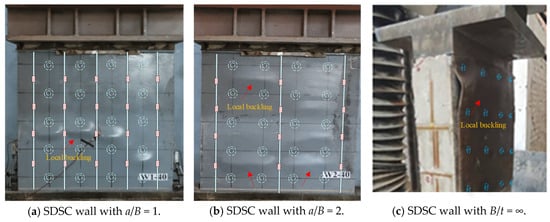
Figure 6.
SDSC walls with different a/B ratios.
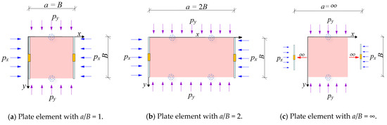
Figure 7.
Changes in the analysis models with different a/B ratios.
Compared to the Euler column formula Equation (3), the critical stress from the modified model has a special buckling coefficient k″. The values of the buckling coefficients k″ with different shape parameters a/B are listed in Table 1. As can be seen in Table 1, it is evident that as the shape parameters’ a/B ratio increases, the buckling coefficient gradually decreases and approaches 1. Ultimately, the modified formula of Equation (1) degrades into Equation (5), which is similar to the Euler formula with two edges that are simply supported (i.e., the effective length factor K = 1.0).
where K is the effective length factor for the hinged–hinged boundary condition, K = 1.0.

Table 1.
Relationship between general buckling coefficient k″ and a/B.
Comparing the theoretical curves of the Euler formula (i.e., Equation (3)) and the modified formula with a/B = ∞ (i.e., Equation (5)), as shown in Figure 8, it can be observed that the two curves almost overlap, and the buckling stresses obtained from the modified thin plate model is slightly higher than those from the Euler column model. The difference is due to the constraint effect between adjacent plate strips in the thin plates.
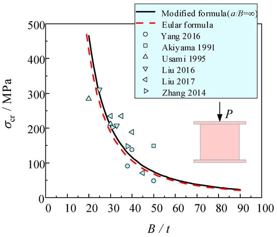
Figure 8.
Comparison of the experimental data with the theoretical curves [14,16,21,22,23,24].
Several experimental buckling stresses of the ODSC walls [14,16,21,22,23,24] are marked in Figure 8. Comparing the experimental data with the curves of the Euler model and the modified model, it is evident that the experimental values are approximately in accordance with the two theoretical curves. Therefore, when the stiffening ribs’ spacing a is much larger than the studs’ spacing B, the critical stress formula considering the constraint effects can almost degrade to the Euler formula with two edges being simply supported.
3. The Applicability of the Modified Model
The previous experiments conducted by the authors revealed that when the a/B ratio is equal to 1 and 2, the biaxial compression model considering the constraint of stiffeners can accurately predict the critical buckling stress of the faceplate. However, for other stiffener arrangements (i.e., varied a/B ratios), the accuracy and effectiveness of this modified method should be discussed specifically. Figure 9 shows an ODSC wall designed by other scholars. Although there is no special stiffener and tie plate to improve the local stability of the faceplate, the side plate of the ODSC wall can also play a similar constraining role as the stiffener, meaning that a steel plate element that is enclosed by stiffeners and studs will be formed accidentally. As the stiffeners’ spacing a is much larger than the studs’ spacing B, the shape parameter will increase, and then, the theoretical value of the local buckling stress will change accordingly.
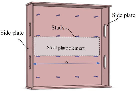
Figure 9.
The analyzed element of the ODSC walls.
More than 50 specimens of the DSC walls [14,15,16,17,18,19,20,21,22,23,24,25,26] that have been developed to study local buckling have been discussed in this section. Among these specimens, the shape parameters of the steel plate element range from 1.9 to 20, and the range of the B/t ratios is 15 to 100. The value of the buckling stress σcr-cal is calculated by a modified formula (Equation (1)), which considers the constraint effects of the stiffeners or side plates. In order to verify the accuracy and effectiveness of the modified model for SDSC walls with different shape parameters a/B, the calculated results σcr-cal are compared with the test buckling stress σcr-test in these studies. It should be noted that when the faceplates achieve the yield stress prior to the buckling stress, the yield stress will be taken as the buckling stress. Subsequently, the relationship of the two values is illustrated in Figure 10.
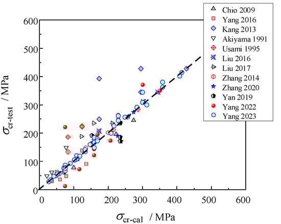
Figure 10.
Comparison between the theoretical values and the test values [14,15,16,17,18,19,20,21,22,23,24,25,26].
As shown in the figure, despite significant deviations being observed in individual experimental data points, the majority of test points are situated on both sides of the 45-degree reference line. This indicates that the modified model exhibits high accuracy and reliability in predicting the local buckling stress of the SDSC walls. Consequently, this study asserts that the proposed theoretical model can serve as an effective tool for guiding the local stability design of SDSC walls.
4. Numerical Simulation and Parameter Analysis
This section will employ ABAQUS 6.14 to conduct finite element (FE) analysis of the SDSC walls. The analysis will comprehensively consider the influences of material properties, geometric characteristics, contact nonlinearity, and initial geometric defects. Through comparison with experimental results, the reliability of the FE models will be validated. Subsequently, utilizing a simulation model, an in-depth exploration will be undertaken to discuss the impact of the geometric dimensions of studs, stiffeners, and tie plates on the local buckling of the SDSC walls. Ultimately, the goal is to provide practical design recommendations that are aimed at preventing buckling in engineering applications.
4.1. Finite Element Models
According to Yang’s suggestion [19,20], the stiffeners are recommended to be arranged along the pressure direction between every two columns of the studs (i.e., a/B =1). So, this part will take the SDSC wall specimens of WA-40, WA-50, and WA-60 as examples, which are reported by Yang et al. [19] and designed with a B/t ratio of 40, 50, and 60, respectively. The shape parameters of these specimens are all set as a/B = 1 (i.e., the stiffener spacing is equal to the stud spacing). Other main parameters of the SDSC walls are listed in Table 2. The basic composition of the FE model of the SDSC walls is shown in Figure 11. For the FE models, the core concrete of the SDSC walls is simulated using 8-node solid elements (C3D8R). The faceplates, side plates, stiffeners, and tie plates are all modeled using 4-node shell elements (S4R). Considering both the stability of results and computational efficiency, a mesh size of 30 mm is deemed appropriate by several trial calculations. In order to simplify the calculation, spring elements are adopted to simulate the behavior of the studs. The mechanical behavior of concrete, steel plates, shear connectors, stiffeners, and tie plates are set based on the author’s previous work [19]. Finally, the ultimate load and buckling stress of the specimens are compared in Figure 12.
Table 2.
Main parameters of the SDSC walls.
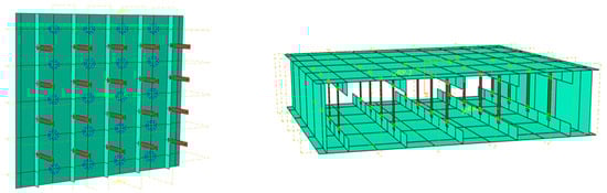
Figure 11.
The basic composition of the FE model of the SDSC walls.
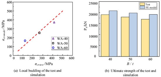
Figure 12.
Local buckling stress and ultimate strength in WA series in test and simulation.
Here, Ec is the modulus of the concrete, Ac represents the cross-sectional area of the core concrete, and fcu and fc are the cubic compressive strength and the axial compressive strength of the concrete, respectively.
As shown in Figure 12a, the points are all near to the reference line, which indicates that this numerical simulation can effectively capture the stress state of the faceplates’ welded stiffeners, and the FE models can effectively predicate the critical stress of the compression faceplates. According to the finite element analysis results, it is evident that the ultimate load-bearing capacities of the three specimens are not significantly different. This is consistent with the findings of Montuori et al. regarding the constitutive behavior of concrete [27,28]. However, as the load eccentricity and the nonuniform distribution of the compression are neglected in FE models, the ultimate strengths of the FE specimens are slightly higher than those of the tested specimens, which is illustrated in Figure 12b. As the primary focus of this experiment is on the local buckling of the faceplates, this numerical simulation method can meet the precision requirements of the study, and a further parameter analysis of SDSC walls can be conducted using this modeling approach.
4.2. Parameter Analysis
In order to simplify the design and widen the application of these SDSC walls in engineering, an appropriate and convenient rule should be proposed to obtain the geometric dimensions of these connectors, such as studs, stiffeners, and tie plates. Therefore, based on the specimens of WA-40, WA-50, and WA-60, a further parameter analysis of the SDSC walls is conducted to study the impact of the connectors on the bucking behavior of the faceplates.
4.2.1. The Influence of the Studs
Taking the specimens of WA-40, WA-50, and WA-60 as examples, as shown in Figure 13, six FE models have been developed which keep the length of the studs as a constant and just change the studs’ diameter (dstud). The relationship between the diameter of the studs and the thickness of the faceplates is shown in Table 3.
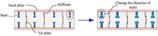
Figure 13.
Changing the diameters of the studs.
Table 3.
The ratios of the stud diameter to the plate thickness (dstud/t).
Through finite element analysis, the relationship between the buckling stress and the dstud/t ratios can be obtained. As shown in Figure 14, it can be observed that when the dstud/t ratio is smaller than 1.67, with the increase in the diameter, the buckling stress of the faceplate increases slowly. When the ratio is greater than 1.67, the buckling stress of the faceplate tends to stabilize. It is indicated that the stud diameter has little influence on the local buckling stress. Due to the constraint of stiffeners and tie plates, the out-plane stiffness of the faceplate is enhanced sufficiently. Therefore, the diameter of the studs has a relatively small impact on the local stability of the SDSC walls.
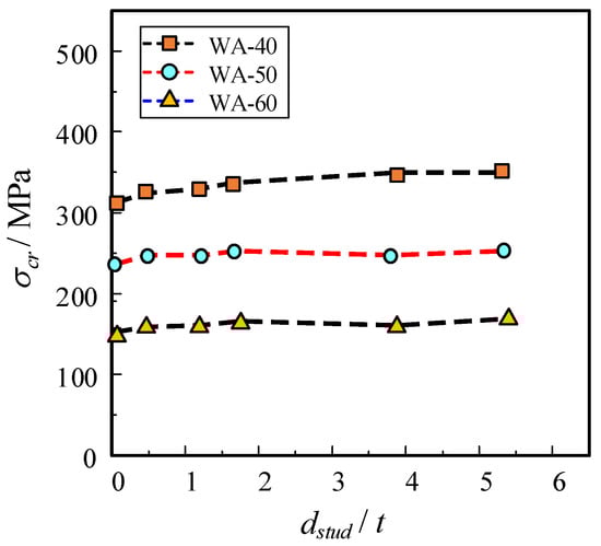
Figure 14.
The relationship between the buckling stress and the dstud/t ratio.
4.2.2. The Influence of the Stiffeners
Based on the specimens of WA-40, WA-50, and WA-60, as shown in Figure 15, a series of FE models have been developed which keep the height of the stiffeners (hstiff) as a constant and just change the thickness of the stiffeners (tstiff). The relationship between the thickness of the stiffeners and the faceplates is shown in Table 4.
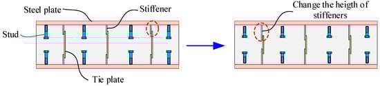
Figure 15.
Changing the thickness of the tie plates.
Table 4.
The ratios of the stiffening thickness to the plate thickness (tstiff/t).
As shown in Figure 16, it is evident that with the increase in the tstiff/t ratio, the local buckling stress of the faceplate gradually increases. Due to the increased thickness of the stiffeners, their restraining ability on the faceplate is enhanced. Therefore, within a certain range, increasing the steel plate thickness will effectively raise the buckling stress. As observed from Figure 16, the change in buckling stress shows a tendency to slow down when the tstiff/t ratio exceeds 0.5. The reason is that the restraining capacity of the stiffening ribs is close to the upper limit at this stage, so the curve of the buckling stress gradually increases with the increase in the stiffener thickness.
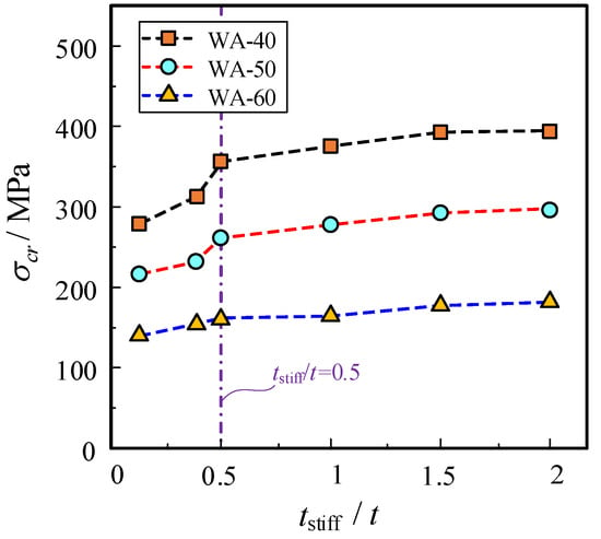
Figure 16.
The relationship between the buckling stress and the tstiff/t ratio.
In addition, the height of the stiffener can affect the out-of-plane deformation ability of the faceplate. Therefore, this section will focus on changing the height of the stiffener (hstiff), which varies from 10 mm to 60 mm, as shown in Figure 17, then, the relationship curve between the buckling stress and stiffener height is obtained.
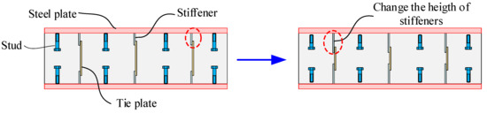
Figure 17.
Changing the height of the stiffeners.
From the Figure 18, it can be observed that the width of the stiffeners has a minor influence on the local buckling stress of the faceplate. This is because when the tie plates are welded on the opposite stiffeners, the out-of-plane flexural stiffness of the faceplate is enhanced significantly. Thus, the local buckling behavior of the SDSC walls is not sensitive to the height of the stiffener changing. Consequently, the local buckling stress of the faceplates remains essentially unchanged.
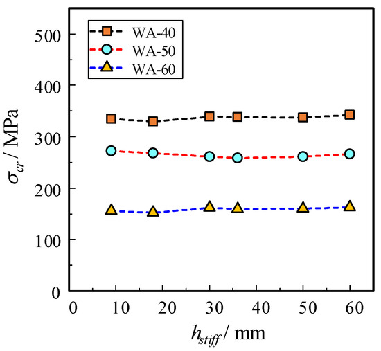
Figure 18.
The relationship between the buckling stress and the stiffener height (hstiff).
Furthermore, during the numerical analysis, an unprecedented failure phenomenon was observed. Taking WA-50 as an example, the differences in the failure are shown in Figure 19 and Figure 20. When the heights of the stiffeners were 18 mm and 30 mm, respectively, the out-of-plane deformations of their faceplates were nearly identical at the early stage of loading. However, in the later stages of loading, significant differences in the failure modes were observed on the two finite element specimens. As shown in Figure 20b, for the specimen with 18 mm stiffeners, the faceplate and the corresponding stiffener exhibited simultaneous buckling. Due to the insufficient height of the stiffeners, the overall stiffness of the stiffeners and the steel plate was inadequate. So, at the later stages of loading, the steel plate and the stiffeners buckled simultaneously.
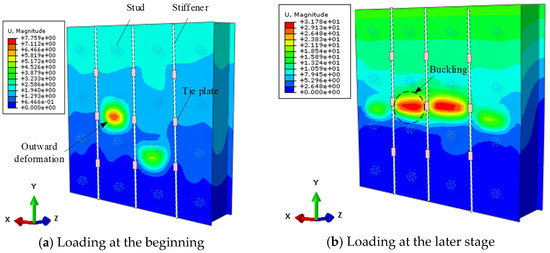
Figure 19.
The buckling mode of the WA-50 with hstiff = 30 mm.
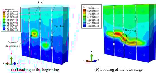
Figure 20.
The buckling mode of the WA-50 with hstiff = 18 mm.
4.2.3. The Influence of the Tie Plates
For the convenience of construction, it is recommended that the stiffeners and tie plates have the same thickness. In this section, numerical analysis is conducted by just varying the width of the tie plates, which is shown in Figure 21. The width of the tie plates (ltie) range from 0.3 mm to 240 mm.
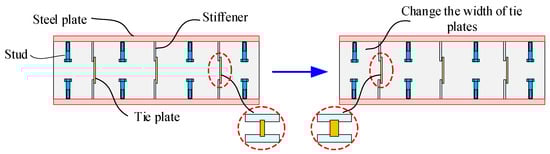
Figure 21.
Changing the width of the tie plates.
As illustrated in Figure 22, when the ratio of the width (ltie) to the thickness (ttie) of the tie plates is smaller than 10, the buckling stress showed an upward trend with the increase in the tie plates’ width. The reason is that the out-of-plane deformation of stiffeners can be confined more effectively with the increase in the width. At this time, the stiffener could act as a fixed boundary, which will clearly increase the local stability of the faceplate. However, there is an upper limit for this constraining effect. When ltie/ttie is higher than 10, the widths of the tie plates will not have a significant impact on the buckling stress.
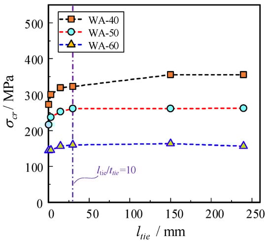
Figure 22.
The buckling stress of the SDSC wall with different thicknesses of the tie plates.
4.3. Constructive Design of Connectors
Due to the limited impact of the stud diameter on the local buckling, it can be concluded that the geometric dimensions of the studs are not a critical parameter. According to the Chinese codes (JGJ-T38-2015 and JGJ99-98-2015), it is recommended that the diameter of the studs does not exceed 1.5 times the thickness of the faceplate, and the length of the studs should be more than 8 times their diameter.
Considering the additional constraining effect of the tie plate, and to save steel material and reduce construction costs, it is suggested that the thickness of the stiffener should not be less than 0.5 times the thickness of the faceplate. Although the width of stiffeners has little effect on the local buckling stress of compressed steel plates, a simultaneous buckling of the faceplate and the corresponding stiffener can be observed during the loading process. To prevent the buckling of the stiffeners due to insufficient stiffness, according to the Chinese codes (JGJ-T38-2015), it is recommended that the stiffness ratio (ψ) of the faceplates and the stiffeners should meet the requirements of Equations (5) and (6). In addition, the following formulas can be used to calculate the width of the stiffeners:
where Le denotes the width of the steel plate element, which can be taken as the spacing of the stiffeners.
For the convenience of the design and construction, it is recommended that the thickness of the tie plate should not be less than the thickness of the stiffener. As the curve of the buckling stress tends to stabilize when ltie/ttie is higher than 10, the width-to-thickness ratio of the tie plate should be no less than 10.
5. Design Procedure
Through the FE analysis, it is observed that the geometric dimensions of connectors can influence the buckling behavior of the faceplate. The appropriate parameters of the connectors not only conserve steel material and reduce welding, they also ensure the accuracy and effectiveness of the modified theoretical model. Therefore, during the design procedures of the SDSC walls, it is essential to first determine the geometric parameters of the connectors and then establish the critical parameters through the modified theoretical model. As illustrated in Figure 23, assuming that the thickness (t) and yield strength (fy) of the faceplate are known, the local stability design of the SDSC wall involves the following two stages:
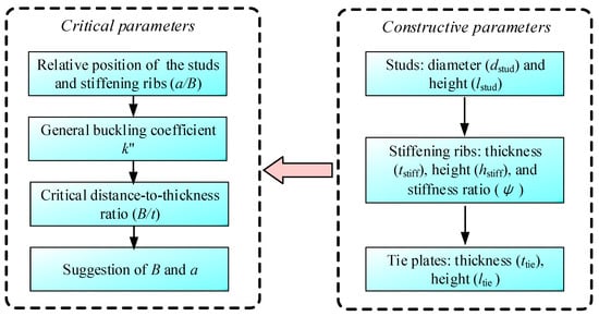
Figure 23.
The design process for the local buckling resistance of the SDSC walls.
(1) Constructive parameters. As the thickness of the steel plate is known, the stud diameter and length can be determined accordingly. Then, based on the numerical analysis results and the requirement for the stiffness ratio (ψ < 1), the thickness and width of the stiffeners can be calculated. Finally, following the recommendations of the tie plate mentioned above, the length and height of the tie plate can be obtained.
(2) Critical parameters. Firstly, choose the appropriate arrangement of the stiffener based on the requirements and obtain the shape parameters (a/B). Then, obtain the general buckling coefficient (k″). To ensure that the yielding of the steel plate occurs prior to local buckling, the critical B/t ratio can be derived by Equations (1) and (2), which will obtain the studs’ spacing and stiffener spacing.
6. Conclusions
In this study, a design method for the local buckling resistance of SDSC walls was thoroughly discussed. Based on the theoretical formula and the experimental data, the characteristics, including the degradation, efficacy, and applicability, respectively, were verified. Based on the numerical parametric studies, some recommendations for the geometric parameters, including studs, stiffeners, and tie plates, are proposed to guide the design of the SDSC walls. The major conclusions can be drawn as follows:
(1) The modified thin plate compression model, which takes into account the constraining effect of the stiffeners, shows its unique advantage, as it can degrade to the Euler column model when the stiffener-to-stud spacing (a/B ratio) approaches infinity. Due to the restraint effect between the continuous plate strips, the curve of the modified formula is slightly higher than the Euler curve.
(2) The analysis model is also applicable for DSC walls with enclosed side plates, for which the enclosed side plates act as stiffeners and restrain the lateral deformation of the steel plate. The effectiveness of the proposed formula is validated by the data in the available literature, and the formula exhibits a strong predictive accuracy with respect to SDSC walls with different geometric parameters.
(3) The simulation results show that the stud diameter has a smaller impact on the stability of the steel plate, and the increase in the stiffeners’ thickness can improve the constraining effect on the faceplate. The stiffness ratio between the stiffener and faceplate should be specifically designed to avoid the joint buckling of the stiffener and the faceplate. The tie plates directly affect the restraining ability of the stiffeners on the faceplates. As the height of the tie plates increases, the buckling stress first increases rapidly and then gradually stabilizes.
Author Contributions
B.W.: Conceptualization, Writing—review & editing, Formal analysis, Methodology, Visualization, Project administration, Funding acquisition. J.-N.W.: Data curation, Formal analysis, Writing—original draft, Writing—review & editing. Y.L.: Methodology, Conceptualization, Supervision. W.-Y.Z.: Writing—review & editing. D.Z.: Formal analysis, Visualization, Writing—review & editing. S.-H.W.: Data curation, Writing—review & editing. All authors have read and agreed to the published version of the manuscript.
Funding
This work was supported by the National Natural Science Foundation of China (Grant Nos. 51878018 and 51878379), the Fundamental Research Funds for the Central Universities (Grant No. YWF-22-L-630 and YWF-21-BJ-J-1131), and the Startup Foundation for Doctoral Research (Grant No. DC2300001260).
Data Availability Statement
Data is contained within the article.
Acknowledgments
Thanks for the work of Wu, J.-N.; Lu, Y.; Zhang, W.-Y.; Zhang, D.; Wang, S.-H.
Conflicts of Interest
The authors declare no conflict of interest.
References
- Narayanan, R.; Lee, I.L. Double skin composite construction for submerged tube tunnels. In Composite Construction in Steel and Concrete II; ASCE: Reston, VA, USA, 1992. [Google Scholar]
- Tan, F. Research on the External Shear Resistance Performance of Steel Plate Composite Walls in Nuclear Facilities. Ph.D. Thesis, Harbin Institute of Technology, Harbin, China, 2015. (In Chinese). [Google Scholar]
- Nie, J.G.; Hu, H.S.; Fan, J.S.; Tao, M.X.; Li, S.Y.; Liu, F.J. Experimental study on seismic behavior of high-strength concrete filled double-steel-plate composite walls. J. Constr. Steel Res. 2013, 88, 206–219. [Google Scholar] [CrossRef]
- Song, S.Y.; Nie, J.G.; Xu, G.P.; Tang, L.; Guo, Y.T. Development and application of double steel plate and concrete composite structure in immersed tube tunnel. J. Civ. Eng. 2019, 4, 109–120. (In Chinese) [Google Scholar]
- Takeuchi, M.; Nkawa, M.; Matsuo, I.; Hara, K.; Usami, S. Study on a concrete filled structure for nuclear power plants. Nucl. Eng. Des. 1998, 179, 209–223. [Google Scholar] [CrossRef]
- Yan, J.B.; Zhang, W. Numerical analysis on steel-concrete-steel sandwich plates by damage plasticity model: From materials to structures. Constr. Build. Mater. 2017, 149, 801–815. [Google Scholar] [CrossRef]
- Davies, J.M.; Hakmi, M.R. Local Buckling of Profiled Sandwich Plates. In Proceedings of the IABSE Symposium-Mixed Structures including New Materials, Brussels, Belgium, 5–7 September 1990; pp. 533–538. [Google Scholar]
- Wright, H.D. Buckling of plates in contact with a rigid medium. Struct. Eng. 1993, 71, 209–215. [Google Scholar]
- Wright, H.D. Local stability of filled and encased steel sections. J. Struct. Eng. 1995, 121, 1382–1388. [Google Scholar] [CrossRef]
- Wright, H.D.; Oduyemi, T.O.S.; Evans, H.R. The experimental behaviour of double skin composite elements. J. Constr. Steel Res. 1991, 19, 97–110. [Google Scholar] [CrossRef]
- Uy, B.; Bradford, M.A. Local buckling of thin steel plates in composite construction: Experimental and theoretical study. Proc. ICE Struct. Build. 1995, 110, 426–440. [Google Scholar] [CrossRef]
- Uy, B.; Bradford, M.A. Elastic local buckling of steel plates in composite steel-concrete members. Eng. Struct. 1996, 18, 193–200. [Google Scholar] [CrossRef]
- Roberts, T.M.; Edwards, D.N.; Narayanan, R. Testing and analysis of steel-concrete-steel sandwich beams. J. Constr. Steel Res. 1996, 38, 257–279. [Google Scholar] [CrossRef]
- Yang, Y.; Liu, J.B.; Fan, J.S. Buckling behavior of double-skin composite walls: An experimental and modeling study. J. Constr. Steel Res. 2016, 121, 126–135. [Google Scholar] [CrossRef]
- Zhang, K.; Varma, A.H.; Malushte, S.R.; Gallocher, S. Effect of shear connectors on local buckling and composite action in steel concrete composite walls. Nucl. Eng. Des. 2014, 269, 231–239. [Google Scholar] [CrossRef]
- Zhang, K.; Seo, J.; Varma, A.H. Steel-Plate Composite Walls: Local Buckling and Design for Axial Compression. J. Struct. Eng. 2020, 146, 15. [Google Scholar] [CrossRef]
- Yan, J.B.; Yan, Y.Y.; Wang, T.; Li, Z.X. Seismic behaviours of SCS sandwich shear walls using J-hook connectors. Thin Walled Struct. 2019, 144, 106308. [Google Scholar] [CrossRef]
- Yan, J.B.; Wang, Z.; Luo, Y.B.; Wang, T. Compressive behaviours of novel SCS sandwich composite walls with normal weight concrete. Thin Walled Struct. 2019, 141, 119–132. [Google Scholar] [CrossRef]
- Yang, Y.; Wu, B.; Xu, L.Y.; Zhang, D.; Wang, S.H. Study on axial compression performance of double steel plate-concrete composite walls with stiffening ribs and tie plates. Eng. Struct. 2023, 274, 115182. [Google Scholar] [CrossRef]
- Yang, Y.; Wu, B.; Xu, L.Y.; Yao, Y.P.; Zhang, D.; Zhao, C. Experimental study on the buckling behavior of double steel plate concrete composite slabs with stiffening ribs and tie plates. Eng. Struct. 2022, 255, 113895. [Google Scholar] [CrossRef]
- Akiyama, H.; Sekimoto, H. A compression and shear loading tests of concrete filled steel bearing wall. In Proceedings of the Transaction of 11th Structural Mechanism Reactor Technology (SMiRT-11), Tokyo, Japan, 18–23 August 1991; pp. 323–328. [Google Scholar]
- Usami, S.; Akiyama, H.; Narikawa, M.; Hara, K.; Takeuchi, M.; Sasaki, N. Study on a concrete filled steel structure for nuclear power plants (part 2). Compressive loading tests on wall members. In Proceedings of the Transactions of the 13th International Conference on Structural Mechanics in Reactor Technology, Porto Alegre, Brazil, 13–18 August 1995; Volume 4. [Google Scholar]
- Liu, Y.B.; Yang, Q.N.; Liu, J.B.; Liao, Y.X. Experimental study on the axial compression performance of double steel plate concrete shear walls. J. Sichuan Univ. 2016, 48, 83–90. (In Chinese) [Google Scholar]
- Liu, Y.B.; Wang, S.; Liu, J.B.; Niu, Q. Experimental study on local buckling performance of double steel plate concrete composite walls. J. Hohai Univ. Nat. Sci. Ed. 2017, 45, 317–323. (In Chinese) [Google Scholar]
- Choi, B.J.; Han, H.S. An experiment on compressive profile of the unstiffened steel plate-concrete structures under compression loading. Steel Compos. Struct. 2009, 9, 519–534. [Google Scholar] [CrossRef]
- Kang, C.K.; Choi, D.J.; Park, H.Y.; Park, H.Y. Compressive characteristics of steel plate-concrete structures using eco-oriented cement concrete. In Proceedings of the Transaction of the 22nd Structural Mechanics in Reactor Technology (SMiRT-22), San Francisco, CA, USA, 18–23 August 2013; North Carolina State University: Raleigh, NC, USA, 2013; pp. 5227–5236. [Google Scholar]
- Montuori, R.; Piluso, V.; Tisi, A. Comparative analysis and critical issues of the main constitutive laws for concrete elements confined with FRP. Compos. Part B Eng. 2012, 43, 3219–3230. [Google Scholar] [CrossRef]
- Montuori, R.; Piluso, V.; Tisi, A. Ultimate behaviour of FRP wrapped sections under axial force and bending: Influence of stress-strain confinement model. Compos. Part B Eng. 2013, 54, 85–96. [Google Scholar] [CrossRef]
Disclaimer/Publisher’s Note: The statements, opinions and data contained in all publications are solely those of the individual author(s) and contributor(s) and not of MDPI and/or the editor(s). MDPI and/or the editor(s) disclaim responsibility for any injury to people or property resulting from any ideas, methods, instructions or products referred to in the content. |
© 2024 by the authors. Licensee MDPI, Basel, Switzerland. This article is an open access article distributed under the terms and conditions of the Creative Commons Attribution (CC BY) license (https://creativecommons.org/licenses/by/4.0/).