Article

A New Macro-Element for Predicting the Behavior of Masonry Structures under In-Plane Cyclic Loading

Univ. Grenoble Alpes, CNRS, Grenoble INP, 3SR, 38000 Grenoble, France
*
Author to whom correspondence should be addressed.
Buildings 2024, 14(3), 768; https://doi.org/10.3390/buildings14030768
Submission received: 23 January 2024 / Revised: 6 March 2024 / Accepted: 10 March 2024 / Published: 12 March 2024
(This article belongs to the Section Building Structures)

Abstract

:
A new macro model for the finite element modeling of unreinforced masonry (URM) exhibiting in-plane nonlinear cyclic behavior is proposed. The ultimate objective is to predict the seismic response of multi-story URM buildings. The macro model enables the modeling of URM shear walls with a limited number of degrees of freedom (DOF) at low computation times. The macro model consists of a deformable elastic frame supported by diagonal struts with nonlinear behavior aiming to capture all dissipative phenomena occurring during seismic events. The nonlinear constitutive behavior of diagonal struts is inspired by models documented in the literature, ensuring a robust foundation for the proposed approach. This paper first provides a comprehensive review of the principal models currently available for URM analysis. It then articulates the rationale behind the development of this new numerical model, aiming to address the limitations encountered in existing methodologies and to offer a simple and fast tool for predicting the seismic behavior of URM buildings. Afterward, the new model is presented and tested with the simulations of two experimental campaigns performed on different URM walls. The comparison between experimental and numerical results shows that with a limited number of DOF and parameters, it is possible to obtain a prediction of the experimental results with satisfying accuracy.

1. Introduction

Unreinforced masonry is one of the most common forms of construction, especially in developing countries. It consists of individual masonry units made of bricks, stones, or concrete blocks connected by mortar joints. Masonry blocks and mortar joints generally have different mechanical properties, making masonry a heterogeneous and anisotropic material with complex constitutive behavior at the macroscopic level [1,2]. For this reason, the numerical modeling of masonry is a difficult task even under simple loading conditions. The difficulty increases for the modeling of a complete building under seismic loading.
The choice of a modeling strategy depends on the expected results. Indeed, a micro model—a term that refers to models in which the masonry elementary components (mortar, blocks, interfaces...) are modeled [3]—aims to reproduce the different physical phenomena occurring in the elementary components of the masonry. The counterpart to the accuracy of the results is a significant computation time. Therefore, the use of such models is irrelevant to the nonlinear transient dynamic analysis of a complete masonry structure.
Macro models have been developed to address this issue; they model masonry using elements that represent the size of a portion of masonry. Among these models, the equivalent strut model (ESM) [4,5,6,7] stands out for its efficiency and effectiveness. It simplifies the modeling process by using a minimal DOF number, relying on a series of diagonal struts to represent the masonry. This approach offers significant advantages, including rapid computation and the ability to closely align with experimental force/displacement data. However, ESM only applies to masonry-filled structures.
An alternative approach is a unified method (UM), which aims to model masonry with a very limited number of degrees of freedom [8,9]. The method consists of modeling a masonry wall, irrespective of the presence of openings, with a horizontal spring to simulate the wall’s shear behavior, and two vertical springs on either side to simulate tension/compression responses. These two vertical springs have elastic behavior, while the horizontal spring is used to model all the dissipative phenomena experienced by the wall under cyclic in-plane loads. The major advantage of this model is its computational efficiency due to the reduced DOF number. Nonetheless, this simplification comes as a drawback, particularly in accurately predicting the behavior of walls with openings, as the model’s shear strength only considers the strength of the piers [9].
To overcome this issue, it is necessary to have a model that explicitly incorporates the openings in the mesh creation process. A prevalent method for this is the pier/spandrel partitioning, commonly known as the equivalent frame model (EFM) [10]. This approach is recommended by international standards, like the Eurocode 8 [11] or FEMA 356 [12]. It consists of assessing a wall’s response to horizontal in-plane forces and, from this, distinguishing the elements that behave differently: the piers (vertical elements that bear both vertical loads and seismic forces), the spandrels (horizontal elements connecting piers, significantly influencing pier behavior by altering their boundary conditions), and rigid panels (areas assumed to remain undamaged). The POR method [13,14,15] was one of the first methods using this kind of identification. This method considers the spandrels as purely elastic and defines piers with an elastic–plastic behavior. Despite its computational efficiency, this method may inaccurately estimate the structure’s lateral strength [16]. Various modeling strategies have evolved, offering nuanced approaches to simulate the complex interactions within masonry elements: (a) the simplified analysis of masonry (SAM) uses beams with elastic–plastic behavior to model the different elements [17,18]; (b) the composite spring method (CSM) uses either elastic or plastic beams with plastic hinges at their extremity [19,20,21]; (c) the macro-frame element (MFE) approach models panels as rectangular elements defined with eight nodes for detailed simulation [22,23]; (d) the double-modified multiple vertical-line-element method (DM-MVLEM) [9], a derivative of the multiple vertical-line-element method (MVLEM) that is used for reinforced concrete structures [24,25], represents piers with multiple vertical elements to capture the flexural behavior accurately, using horizontal springs for shear behavior; (e) the multi-pier (MP) [7] approach models masonry structures by utilizing vertical trusses to represent piers and horizontal trusses for spandrels. The vertical and horizontal elements of the trusses are used to simulate the rigidity and flexural behavior of the masonry. The diagonal braces are used to model the inelastic behavior for traction/compression and shear loading conditions. The difficulty with all these models is that there is no absolute definition for the identification of the different elements and their mechanical properties. This can lead to potential inaccuracies [26]. Consequently, the user needs a deep understanding and a high level of expertise to make relevant hypotheses that allow an adequate identification.
Another macro-element is frequently encountered in the literature for masonry walls’ in-plane behavior: the rigid body spring model (RBSM) [2,27,28,29]. In this model, each rigid element is interconnected through a combination of two normal springs and one tangential spring. These springs are characterized by their inelastic behavior. Even though this kind of model has demonstrated impressive outcomes, its implementation poses challenges since the springs constitutive law relies on a representative equivalent volume and requires a complex identification of parameters. Thus, its definition is more laborious than for the other models.
The rigid macro-element model (RMEM) proposed by Calió et al. [30], and found in several other studies [31,32,33], does not present such a complex definition of elements. In the RMEM, masonry is modeled with rigid frames, interconnected by normal springs that simulate the masonry’s tension/compression dynamics, and tangential springs for possible sliding modeling. It is advised to have at least two normal springs and one tangential spring per side, but it is possible to have more. To accurately model the shear behavior within these frames, diagonal springs are employed, with one spring per diagonal. The nonlinear constitutive behavior of diagonal springs is chosen in order to reflect the macroscopic responses of masonry to various stresses, thereby providing a nuanced and precise representation of masonry behavior. The properties of this macro-element do not depend on the position of the modeled masonry portion in the structure and the brickwork; they are simply defined by their mechanical properties. This straightforward approach, however, encounters challenges when integrating structural components other than masonry. Indeed, the RMEM employs discrete elements connecting the macro elements, whereas the additional elements are usually modeled using finite element beams; the combination of both models is challenging. Pantó and Rossi [34] developed the RMEM using finite elements only. In the latter version of the model, there is an increase in DOF per macro-element from the original 4 to 28. This modification, while enhancing the model’s detail, introduces a significant increase in complexity.
In response to the limitations identified in existing macro-element approaches within the literature, the deformable frame model (DFM) is proposed. It is inspired by the RMEM [30,34] and consists of a frame with internal diagonal struts. It is designed for the ease of mesh generation and the straightforward inclusion of architectural features such as openings. As for the RMEM, its mechanical properties are directly correlated with those of the modeled masonry and do not rely on any representative equivalent volume. Moreover, it is based on finite elements to enable easy integration of non-masonry structural elements, such as timber lintels, concrete frames, or horizontal seismic bands. Unlike the RMEM developed for finite elements [34], the frame of the DFM is deformable under vertical and horizontal loads. This approach is similar to those of the methodologies employed by the UM [8] and the multi-pier [7] and it eliminates the need for interface springs to simulate vertical and horizontal rigidity. Yet, unlike the UM and the multi-pier approach, the frame is made of struts and not beams. The diagonal struts are used to accurately capture the shear behavior of masonry, like for the RMEM, making them the sole components that exhibit inelastic behavior. To optimally represent dissipative phenomena with a limited DOF number, the DFM utilizes constitutive laws initially proposed for the ESM [5]. This approach ensures a faithful representation of masonry’s inelastic behavior during seismic events, optimizing both accuracy and computational efficiency.
In the following sections, the DFM is defined for simulating masonry subjected to in-plane loads. The DFM enables the modeling of three-dimensional structures, with the underlying assumption that nonlinear dissipative phenomena within the walls are solely due to in-plane loads. The different components of the macro-element are described alongside the methodology for identifying their constitutive properties. Subsequently, the incorporation of additional structural elements is tackled. These elements broaden the scope of the DFM, allowing it to model structures that are not purely composed of URM. Finally, the DFM is validated through simulations of two cyclic tests from existing literature, comparing the numerical outcomes with experimental data. The first test demonstrates the ability of the DFM to predict the shear behavior of masonry piers while the second test demonstrates its ability to predict the shear behavior of a wall with openings. These demonstrations highlight the DFM’s robustness and versatility in modeling complex URM walls under cyclic loading conditions.

2. The DFM for In-Plane Loads

Figure 1 shows the modeling of an in-plane-loaded URM wall with the DFM. The model can represent either a section or the full extent of a URM wall. It is defined with four nodes, one at each vertex, having 2 DOF for a total of 8 DOF. As shown in Figure 1, each node is interconnected with three struts: a horizontal strut, a vertical strut, and a diagonal strut.
Masonry damage under horizontal cyclic loading is assumed to be a consequence of its shear behavior. Consequently, within this context, only the pair of identical diagonal struts exhibit nonlinear constitutive behavior. All other elements of the DFM have linear elastic behavior.

2.1. Stiffness of the Struts

The stiffness of each strut can be identified thanks to the virtual work principle by establishing an equivalence between a homogeneous and isotropic 2D medium and the macro-element. An example is shown in Figure 2, and details of the calculations are given in Appendix A. The masonry element of height h m , width l m , and thickness t m is under a uniformly distributed vertical force ( F v ) that leads to a vertical displacement ( u v ) at the top of the wall. The 2D homogeneous and isotropic medium has a Young’s modulus ( E m ) and a shear modulus ( G m ). It is initially modeled with only one macro-element whose vertical, horizontal, and diagonal struts have stiffnesses of K v , K h , and K d , respectively. For the example in Figure 2, the equivalence leads to the following:
  • Homogeneous and isotropic medium (Figure 2a):
    F v ̲ · u v ̲ = σ = : ε = d V = E · l m · t m u v 2 2 h m
  • DFM (Figure 2b):
    F v ̲ · u v ̲ = 2 · 0.5 · K v · u v · u v + 0.5 · K d · u d · u v
    = K v u v 2 + K d cos 2 ( θ ) · u v 2
Equations (1) and (2) allow determining the vertical strut stiffness.
K v = E m · l m · t m 2 · h m K d · cos 2 ( θ )
The stiffness of the horizontal and diagonal struts can be similarly obtained:
K h = E m · h m · t m 2 · l m K d · sin 2 ( θ )
K d = G m · l m · t m 2 · h m · sin 2 ( θ )
The stiffness of both horizontal and vertical struts within the DFM is intricately associated with the stiffness of the diagonal struts. This interdependency is crucial, as it can result in negative stiffness values if the properties of the macro-element fail to meet specific criteria. To address this, it is essential to consider the relationship between the shear modulus, G m , the Young modulus, E m , and the Poisson’s ratio, ν m , of the masonry that is expressed as G m = E m / ( 2 ( 1 + ν m ) ) . As a consequence, the slenderness of the DFM has to follow the following:
1 2 ( 1 + ν m ) h m / l m 2 ( 1 + ν m )

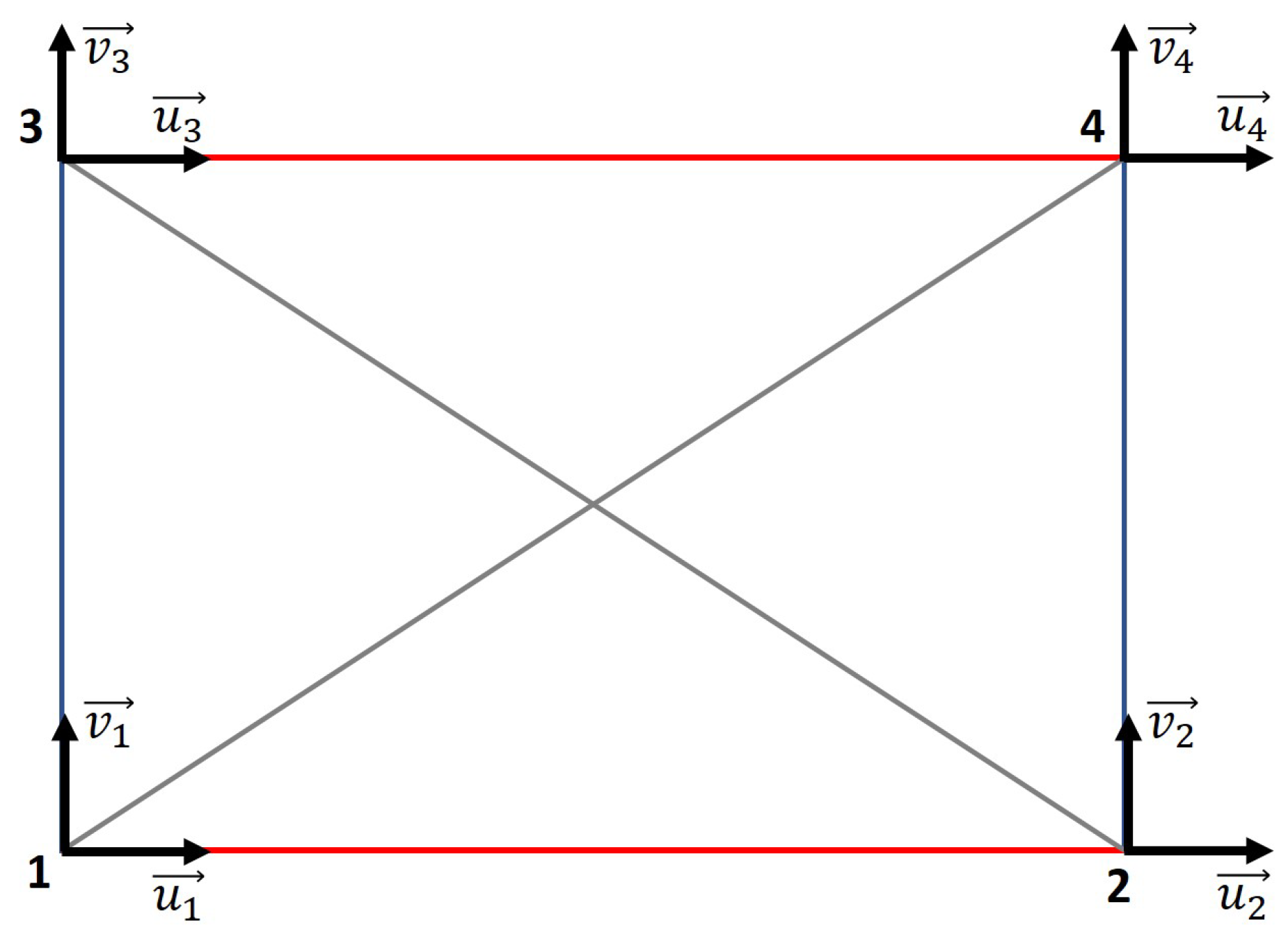
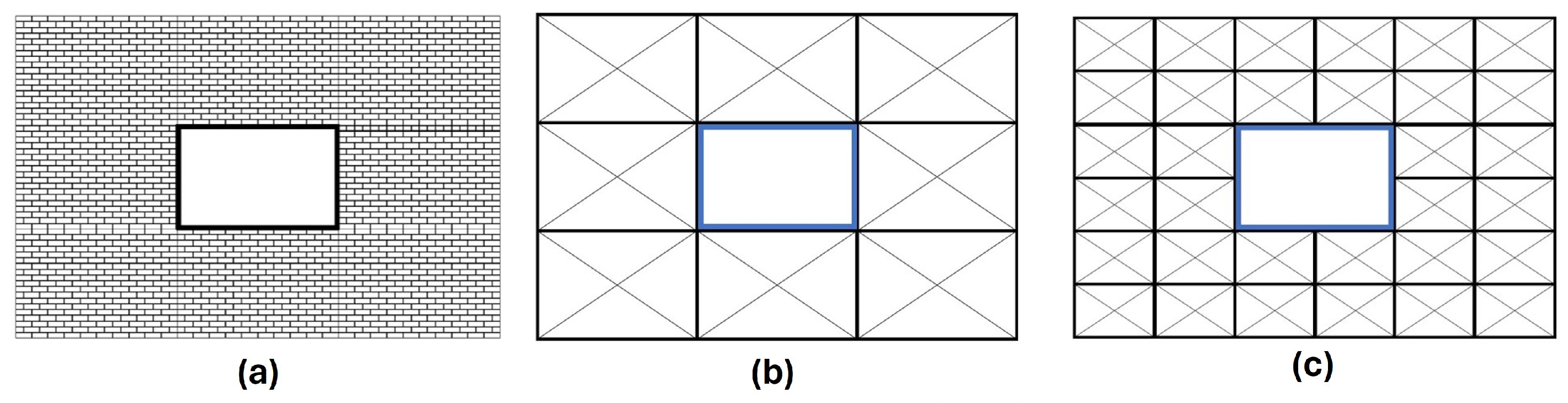
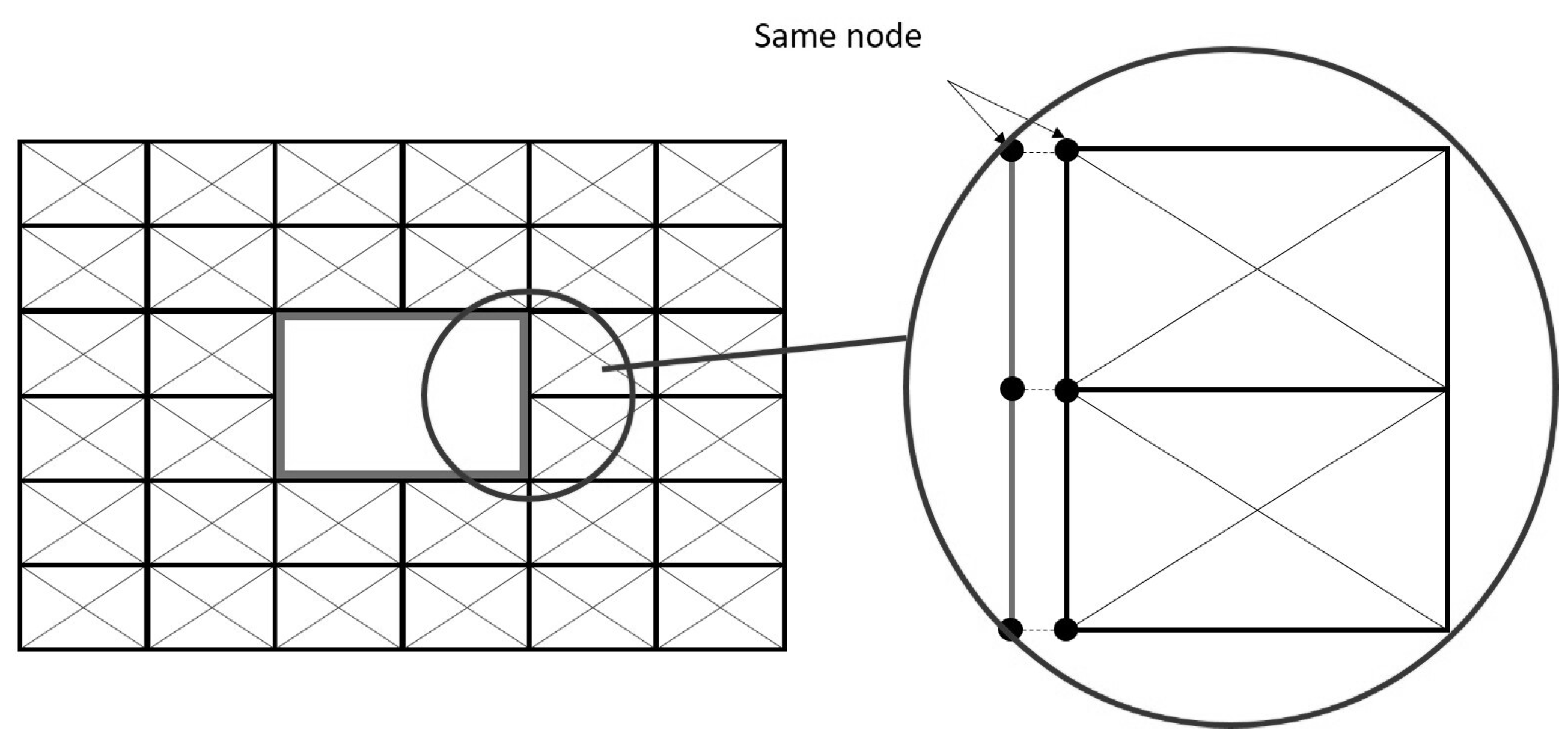
2.2. Macro-Element Discretization

The masonry under consideration can be modeled with more than one macro-element, leading to situations where the neighboring DFM elements share nodes. A smaller number of macro-elements allows reducing the computation time; however, this approach may lead to an inaccurate prediction of the behavior of the wall. An example of a 2 × 2 macro-element configuration is proposed in Figure 3. In this example, the macro-elements have the same size, but they can also have different sizes. The stiffness of a strut adjacent to two macro-elements is the result of the contributions from both. In Figure 3, one can see the horizontal strut located at the centers of the gray rectangle borders’ macro-elements i and j. The stiffness is, thus, given by the following equation:
K h = E m · h i n f · t m 2 · l i K d , i sin 2 ( θ i ) K d , j sin 2 ( θ j )
In the same way, the stiffness of the vertical strut shared by macro-elements j and k is as follows:
K v = E m · l i n f . t m 2 . h j K d , j cos 2 ( θ j ) K d , k cos 2 ( θ k )
In these equations, θ i is the angle of the diagonal strut with the vertical in the macro-element, i; K d , i is the stiffness of the diagonal struts of the macro-element, i; h i n f = 0.5 ( h i + h j ) is the height of the horizontal strut area of influence; l i n f = 0.5 ( l j + l k ) is the width of the vertical strut area of influence.

2.3. Shear Strength of the DFM
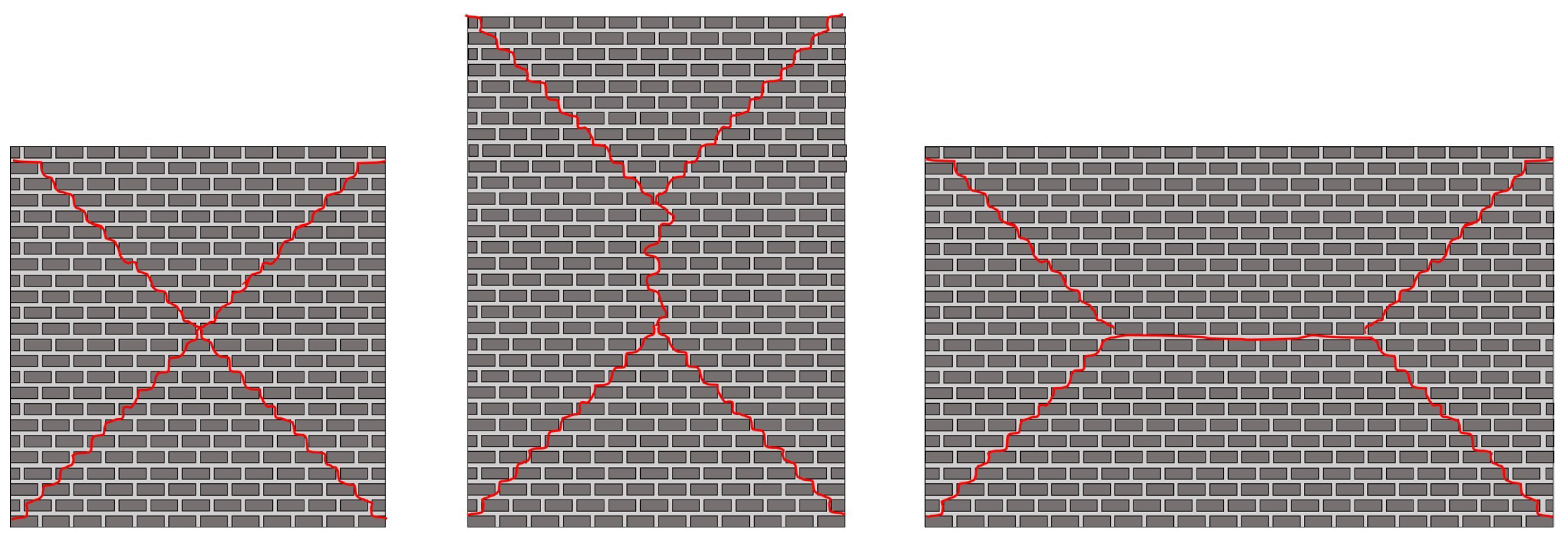
There are three main modes of failure for a masonry pier subjected to shear: rocking, diagonal cracking, and shear-sliding. The maximum strength of the DFM identical diagonal struts is defined by two of them: the diagonal cracking with the formula proposed by Turnšek and Čačovič [35] (Equation (9)) and the shear/sliding with the Mohr–Coulomb’s law modified by Mann and Muller [36] (Equation (10)). Since the macro-element can rotate, it is possible to capture the rocking behavior without defining a maximum shear stress for it.
  • Diagonal cracking:
    f v , 1 = f t b σ v f t + 1
  • Shear/sliding:
    f v , 2 = c ¯ + μ ¯ · σ v
In Equation (9), f t is the tensile strength of the masonry, and σ v is the vertical stress applied to the masonry. The parameter, b, allows accounting for the slenderness of the URM wall and is defined by Equation (11). In this equation, h e l e m and l e l e m are, respectively, the height and the width of the macro-element of the considered diagonal strut.
b = h e l e m / l e l e m with the limits 1 b 1.5
Parameters c ¯ and μ ¯ in Equation (10) are refined adjustments for the cohesion and the friction coefficient, respectively. These modifications were proposed by Mann and Muller [36] to enhance the correlation between the calculated shear strength and the values measured experimentally. They are defined by Equations (12) and (13), where H b is the brick’s height and L b is its length.
c ¯ = c 1 + 2 · μ H b L b
μ ¯ = μ 1 + 2 · μ H b L b
The maximum strength of the diagonal strut, F u , is defined by considering the two definitions of the shear stress given by Equations (9) and (10) and the shape of the DFM element, as shown in Equation (14). In this equation, θ e l e m is the inclination of the diagonal strut with respect to the vertical direction. It is important to note that this determination of the diagonal strut’s maximum strength is conducted at the meso scale, rather than at the macro scale.
F u = l e l e m · t m sin ( θ e l e m ) min ( f v , i )

2.4. Inelastic Behavior of the DFM

The diagonal struts allow accounting for the inelastic behavior of the macro-element under in-plane loading. Figure 4 shows the hysteresis behavior under alternate shear loading; it is inspired by the model proposed by Panagiotakos and Fardis [5], originally developed for the ESM. It allows reproducing the inelastic behavior of the masonry under cyclic shear loading with few parameters, compared to other similar models. The envelope curve is bilinear (shown as a bold line in Figure 4). The plateau at force, F u , corresponds to the effect of failure. The decrease in the ultimate force at α F u ( α < 1) is a consequence of the cyclic loading.
The unloading–loading path is the one proposed by Panagiotakos and Fardis [5], and the only empirical parameters are α , β , γ , initially defined with positive values. β and γ are used to control the shape of the hysteresis loop; they are necessary to reproduce the dissipative phenomena noticed during a cyclic test. The first complete unloading–reloading is represented by the path BC-CD-DE and the second complete unloading–reloading by the path FG-GH-HI or FG-GH-HI’ in the case of the cycle. The latter refers to a complete cycle when the wall has been damaged in both directions of solicitation; the gray bold line corresponds to failure at force α · F u . In order to better understand the loading–reloading behavior, the two different paths are explained.

2.4.1. Damage in One Direction

In the path represented by branches BC-CD (Figure 4), the ultimate force (resp. ultimate displacement) of the modeled masonry portion F u (resp. du) is reached in only one direction. This does not necessarily mean that the wall has been loaded in only one direction. The unloading path in this case is as follows:
1.
From point B, the unloading occurs with initial stiffness, K d . This behavior occurs until the force β · F u is reached at point C in Figure 4.
2.
After point C, the stiffness decreases, corresponding to the opening of the cracks produced by the solicitation in this direction. Since the modeled masonry portion has not been damaged in the other excitation direction, the point targeted by the constitutive law is the point of ordinate - β · F u on the envelope curve; see point D in Figure 4. After this point, the DFM follows the behavior of the envelope curve.

2.4.2. Damage in Both Directions

It is represented by the path FG-GH-HI (or FG-GH-HI’). In this case, the ultimate force of the modeled masonry portion, F u , has been reached in both directions. The maximum displacement reached in the opposite direction is denoted as d m a x . For the path described in Figure 4, d m a x = d B . The unloading path in this case is as follows:
1.
From point F, the unloading takes place with the initial stiffness, K d , as from point B. The branch FG is described exactly as the branch BC.
2.
After reaching point G, the following branch is not defined like the branch CD. Since the modeled masonry portion has already been damaged in the opposite direction, some cracks remain open due to the reloading. Thus, two phenomena occur on the branch GH: the closing of cracks in one direction and the reopening of cracks in the other direction. Note d β F u = γ · ( d m a x d u ) is the displacement at force β · F u in the other direction.
3.
Depending on the mode of failure that occurs, the last part of the curve is defined differently.
  • At point H, the masonry exhibits damaged stiffness until the ultimate force, F u , is recovered. Therefore, point I in Figure 4 is different from point B. After point I, one follows the envelope curve again. This type of behavior occurs if the failure is along a bed joint.
  • If the failure is along the wall portion diagonally, the masonry has softening behavior due to cyclic damage. The ultimate force at displacement d m a x is no longer F u , but α F u with α < 1. The value α F ( d m a x ) is chosen as the new maximum of the envelop curve as shown in Figure 4 with the branch HI’. After point I’, the new definition of the envelope curve is followed.

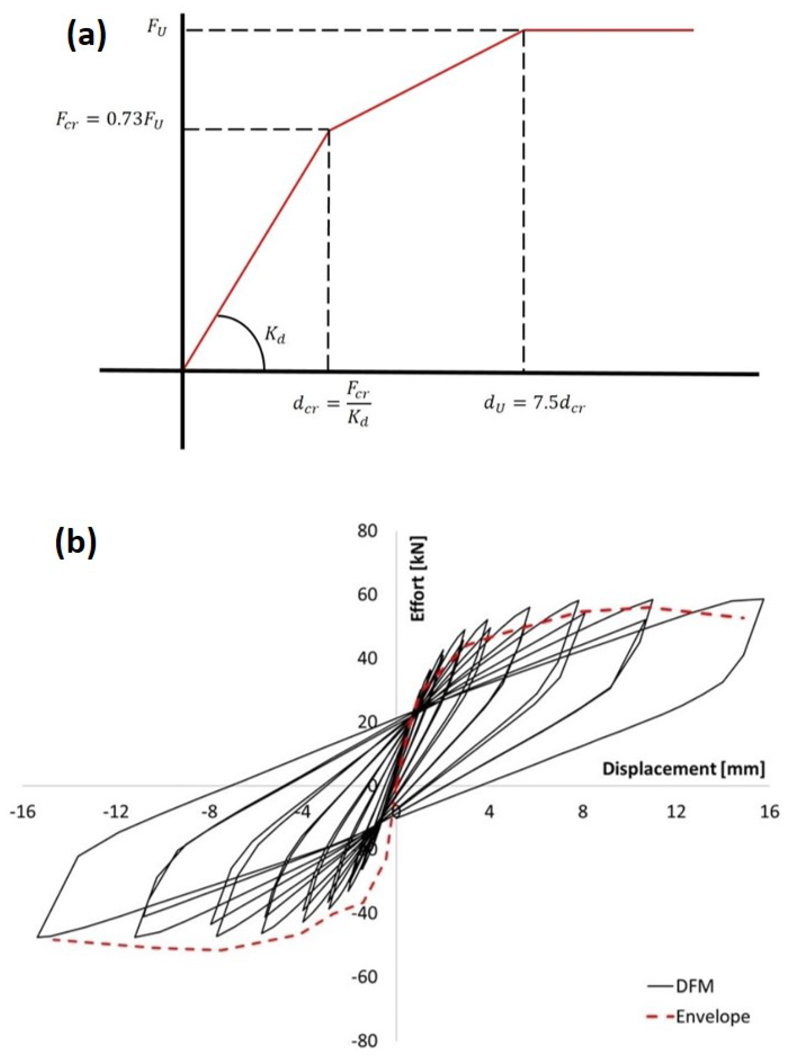
2.5. Parameters of the Hysteresis Constitutive Model

Panagiotakos and Fardis [5] did not provide any definition for the parameters defining the hysteresis. In order to predict the cyclic behavior of masonry structures without the help of experimental cyclic tests, formulas for α , β , and γ are proposed. These empiric formulas are defined to approximate values determined by fitting experimental curves on walls without openings. It is supposed that the values of the parameters are the same in the two directions of loading.
The parameter α is used to reproduce the softening behavior of masonry associated with cyclic loading. The deterioration of the properties of the wall depends on its slenderness and the vertical load. Since the strength of masonry associated with diagonal failure increases with the vertical loading, it is assumed that the cyclic damage is inversely proportional to the vertical loading. Finally, Decret [37] identified the parameter α with Equation (15).
α = 0.9 + b d i a g 1 1 + σ v / f t
The parameter ( b d i a g ) in Equation (15) is similar to the parameter (b) used to define the maximum strength of the diagonal element in Equation (9). However, its definition is slightly different, as shown by Equations (16) and (17). The parameter ( b d i a g ) is inspired by the crack patterns of diagonal cracks, which depend on the slenderness of the walls, as shown in Figure 5, and the definition of the parameter (b) in the literature, which differs for masonry piers and spandrels [35]. The crack pattern affects the cyclic behavior of the wall.
  • if h e l e m > l e l e m
    1 b d i a g = h e l e m / l e l e m 1.5
  • if h e l e m < l e l e m
    1 b d i a g = l e l e m / h e l e m 1.5
Parameters β and γ define the stiffness variation of the wall during the unloading–reloading stages and the global shape of the hysteresis loop. They only depend on the slenderness of the wall. Decret [37] identified the dependence of parameters β and γ on the slenderness with Equations (18) and (19).
β = 0.2 b d i a g 2 + ( 1 b d i a g ) 2
γ = 0.4 + 2 ( 1 b d i a g )

3. Wall with an Opening

The presence of an opening in the wall is accounted for thanks to the discretization. An example of masonry wall modeling using DFM, including an opening reinforced by a frame, is shown in Figure 6 with different mesh sizes.
The DFM can only be used to model masonry wall portions. For the modeling of additional elements in a structure, such as reinforcements, the macro-elements have to be connected to additional elements around openings (Figure 6). Elastic beam elements are used to model the frame, as represented in Figure 7. The beams share the same nodes as the DFM macro-elements.
There are a few special features for modeling lintels. Since the nodes of the beam coincide with the nodes of the macro-elements, the lengths of the lintels have to match the sizes of the macro-elements on the frontier. That constraint may have an important impact on the mesh size and on the computation time. Therefore, it is suggested to create the DFM mesh first and to adjust the size of the beam elements to the created mesh. The impact of this choice of modeling is shown in a case study in Section 4.2.

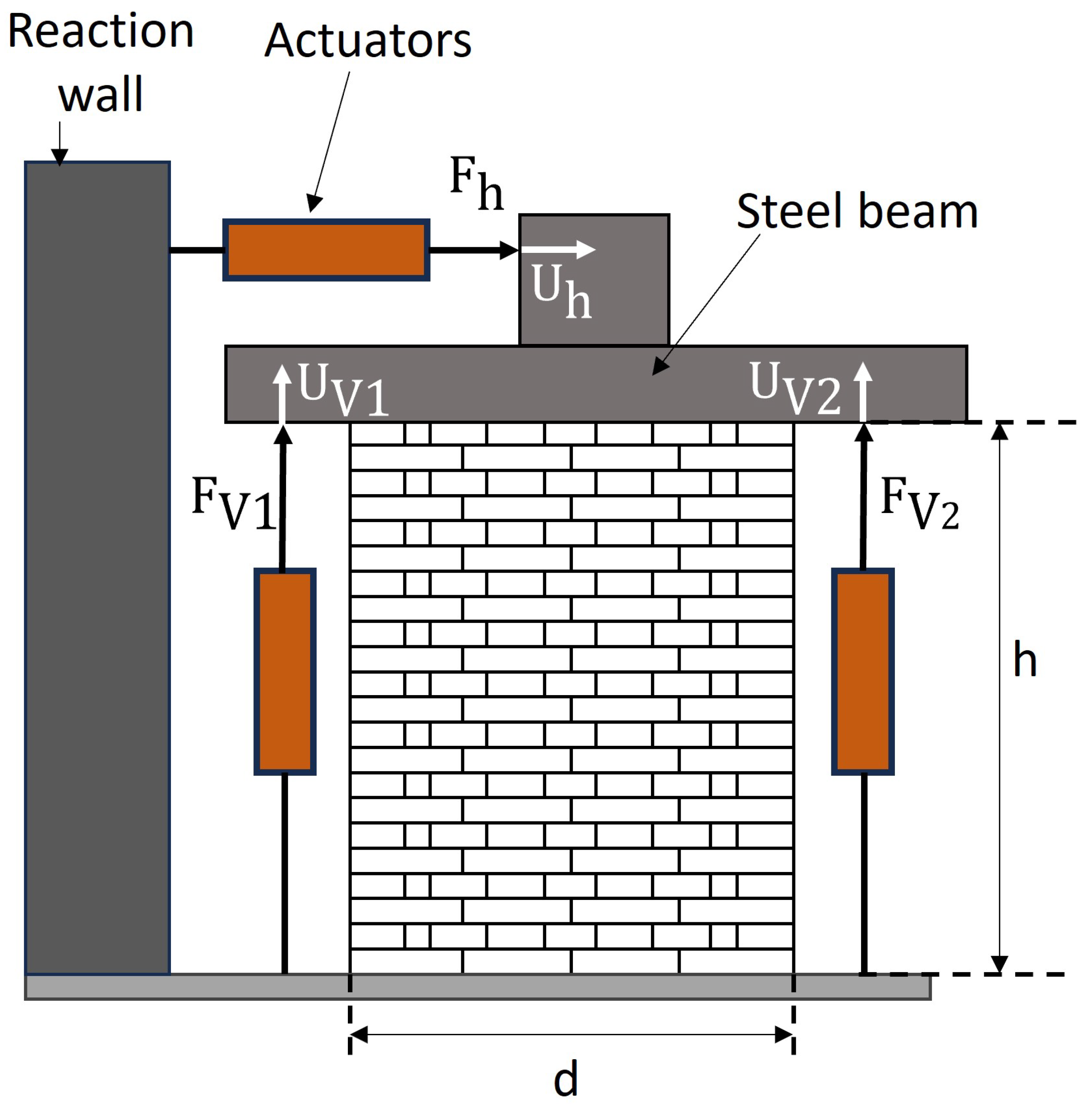
4. Validation of the Macro-Element Model
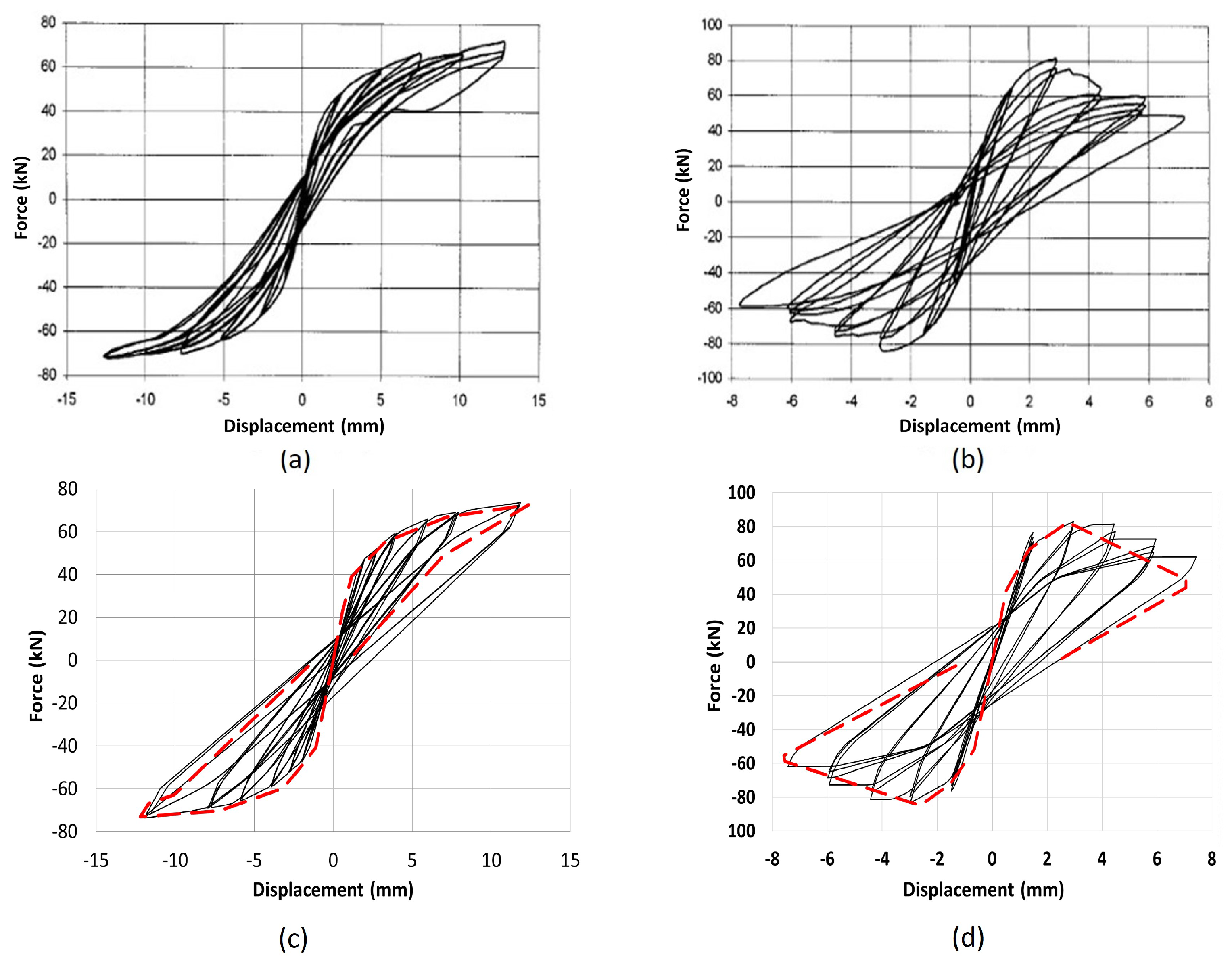
The DFM is used to model two different experimental campaigns. The first experiments by Anthoine et al. [38] have already been used to validate various numerical models [27,39,40]. They consist of three cyclic tests on two different walls without opening, made of Italian bricks. The second experimental campaign by Reyes et al. [41,42] consists of cyclic tests performed on two wide walls, made of rammed earth and adobe. These latter walls have two openings and lintels. The two numerical models were implemented in ATL4S, a finite element toolbox for Matlab [43].

4.1. URM Piers

The test results presented by Anthoine et al. [38] aim to study the in-plane behaviors of two different pier walls with the same width and thickness but different slendernesses (Figure 8). The smallest wall is 100 × 135 × 25 cm3 (L × H × T) in size and the highest one is 100 × 200 × 25 cm3. The heights of the two walls were chosen to exhibit two different failure patterns: a flexural/rocking failure for the high wall and a diagonal shear failure for the small one; 5.5 × 12 × 25 cm3 bricks arranged in English bond were used for both walls.
The experimental setting was designed to prevent the rotation of the wall so that the test would reproduce—as closely as possible—the conditions of pure shear. For this reason, the assumption of a doubly restrained wall was made. The shear loading was produced by an imposed cyclic displacement at the top of the wall. Two cycles of the same amplitude were performed. If a noticeable loss of strength was observed during these two cycles, a third cycle was performed. In addition to the cyclic displacement, a vertical compressive stress of σ v 1 = 0.6 MPa was applied to the walls.
The mechanical properties of the masonry are shown in Table 1. The parameters α , β , and γ , defining the hysteresis of the diagonal struts, are determined with Equations (15)–(19). Their values are given in Table 2. The value of α varies, depending on the position of the macro-element as the vertical stress σ v changes.
The experimental results of the high and small walls are shown in Figure 9a,b respectively. As expected by Anthoine et al. [38], the two walls exhibit quite different cyclic behaviors and have different modes of failure. The high wall exhibits large displacements without significant strength loss and with limited energy dissipation. This is typical of rocking failure where only small cracks occur, leading to limited energy dissipation. In contrast, the small wall exhibits significant strength loss and much higher energy dissipation. This is due to diagonal crack failure.
The responses of the high and small walls as predicted with the DFM are shown in Figure 9c,d, respectively. The quality of numerical results can be evaluated regarding the ability of the model to predict both the envelope curve and the hysteresis behavior. Whether it be for the small wall or the high wall, the macro model succeeds in predicting well the envelope curve and the post-failure part. The major difference occurs for small displacements for the small wall, where the model slightly overestimates the strength in the positive direction and underestimates its initial rigidity. That observation can be explained by the inability of the model to predict an asymmetrical cyclic response for the masonry.
The DFM also succeeds in predicting cyclic behavior with quite good accuracy. For the high wall, the experimental curve exhibits a behavior with a pinching at the highest cycle that is not well reproduced with the model. Yet, the model can well reproduce the rest of the loops and provide a good prediction of the plastic deformation. The small wall has more cracks during the test and the model does not provide a good prediction of the dissipated energy for small displacements. This can be explained by the use of a bilinear envelope curve that does not consider a softening behavior after the occurrence of cracks. However, once the ultimate strength of the wall has been reached, the DFM succeeds in giving a good prediction of the hysteresis loop.

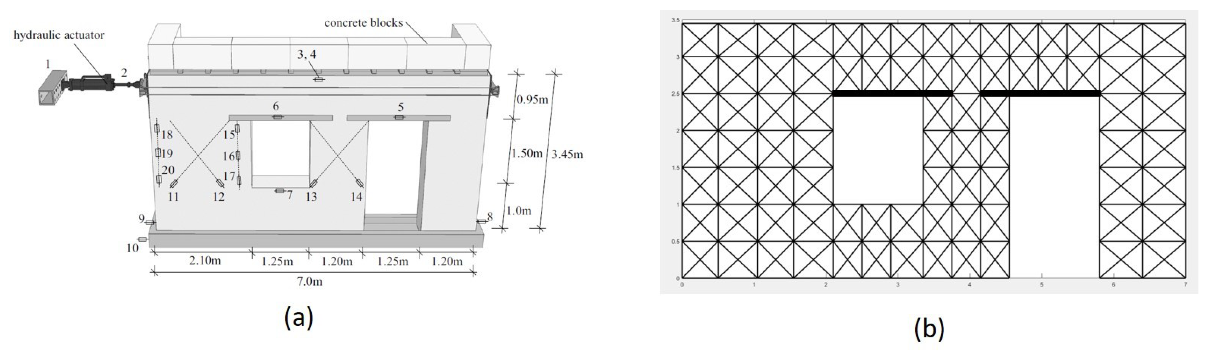
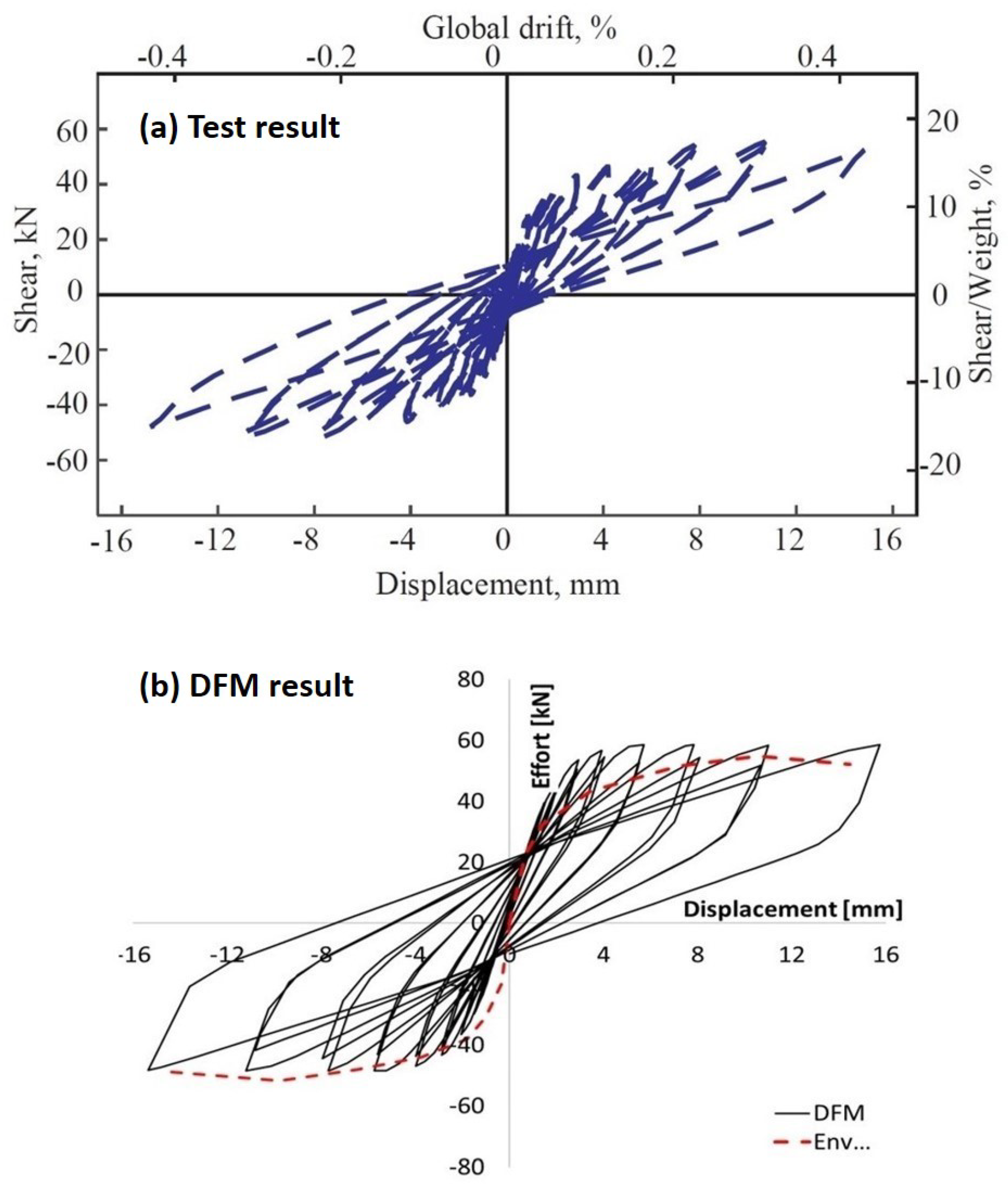
4.2. Wide Walls with Openings

The second validation test involves simulating a wall with openings, utilizing the experimental campaign conducted by Reyes et al. [41,42]. This experimental campaign, which is described in the two articles, encompasses a series of tests on URM and retrofitted walls. For the validation of the DFM, the focus is exclusively on the unreinforced adobe wall.
The tested wall is shown in Figure 10a. Its design is inspired by the typical architecture of heritage earthen structures in Colombia. On each side of the wall, there is a short buttress to account for the influence of the perpendicular walls (not shown in Figure 10a). On the wall, concrete blocks are used to exert a total vertical force of 51.86 kN. The wall’s foundation is made with a reinforced concrete beam that is connected to the laboratory reaction floor with post-tensioning anchors. Since nothing blocks the top of the wall vertically, it is modeled as a cantilever wall. The displacement is applied through a hydraulic jack on one side of the wall, connected to a system capable of pushing and pulling the wall. The first displacement has a value of 0.2 mm and is increased every cycle by a factor of 1.4 until reaching the value of 15.8 mm.
Table 3 shows the mechanical properties of the adobe wall. Most parameters have been determined using the data from Reyes et al. [41,42]. The elastic properties of the adobe wall are not reported in these articles. However, the elastic properties of the rammed earth wall are reported. The cyclic tests of the two walls show that both walls have similar initial stiffness. Therefore, the elastic modulus and Poisson’s ratio of the rammed earth wall in Reyes et al. [42] are assumed to be the elastic properties of the adobe wall. The cross-section of the lintels is determined based on the figures in the two articles.
The thick beam elements in Figure 10b represent the lintels above the openings. They are not centered on the opening because of a modeling choice: it has been decided to reduce the size of the lintel to the closest element node. As a consequence, the modeled lintel is always of the same size or smaller than the real one.
The experimental results obtained for the adobe wall are shown in Figure 11a and the force/displacement curve obtained with DFM is shown in Figure 11b, where the red dashed line is the envelope curve of the experimental results. The model underestimates the initial stiffness of the adobe wall in the pulling direction, but the difference remains low. Regarding the maximal strength of the wall, it is overestimated by 20% in the pushing direction, but it was well estimated in the pulling direction. The reason behind this overestimation of the maximal strength of the wall in the pushing direction is related to the use of a bilinear curve for the shear behavior of the DFM. This choice results in excessively high stiffness for small displacements and, thus, overly high strength for the wall.
To improve the results of the DFM, it is possible to use a trilinear behavior for the diagonal struts, as the displacement and the force at the occurrence of the cracks and the ultimate state are given by Reyes et al. [41]. The new envelope curve for the diagonal elements is given in Figure 12a with the values of the parameters. With such an envelope curve, the diagonal strut has a hysteresis behavior as soon as its deformation is higher than the displacement, d c r , defined in Figure 12a. Figure 12b shows the result of the model with this enhancement. As expected, the envelope curve is better predicted by taking a trilinear curve for the diagonal elements. The error now is approximately 15%, which is satisfactory knowing that there are uncertainties linked to the material properties. However, the behavior in the pulling direction is less accurate than the trilinear behavior. This limitation stems from the application of a symmetric constitutive law, which fails to account for the asymmetric behaviors intrinsic to an actual wall, including its tendency to experience rocking.
The average values for the parameters defining the hysteresis are calculated with Equations (15)–(19). Since the DFM macro-elements modeling the walls do not have the same vertical load or the same shape, the values vary from one element to another. The average values for α , β , and γ are 0.87, 0.4, and 0.1, respectively.
As stated above, the lintels in the model do not have the same lengths as the real ones for a mesh size purpose. Since the mesh is coarse, the lintels in the model can be quite smaller compared to the real ones. To evaluate the influence of this simplification on the results, three different meshes are compared (Figure 13). The first case is the one used above (intermediate lintel lengths). The second case corresponds to an extension of the lintel to the closest node (long lintels). The last case involves the modeling of the lintel only above the opening and not in the masonry (short lintels).
The push-over curves of the three cases are shown in Figure 14. This figure shows that the modeling of the lintels has a slight influence on the push-over behavior of the walls. In order to correctly reproduce the experimental results, the choice was made to model the lintels thanks to elastic beam elements in addition to the masonry with DFM elements. Since the lintels have elastic behavior, this does not add a noticeable extra computational time.

5. Conclusions

In this paper, the DFM, a new finite element macro model used to predict the in-plane nonlinear cyclic behavior of URM, is proposed. The DFM is structured as a frame made of horizontal and vertical elastic struts. Within it, diagonal struts are used to simulate all the dissipative phenomena that occur during in-plane cyclic loads. The DFM’s behavior is defined with only 8 DOF—namely the vertical and horizontal displacements at each vertex).
The modeling of a masonry structure with the DFM is straightforward. It is not necessary to identify specific components within the wall (piers and spandrels), as the presence of openings is directly accommodated through the model’s meshing technique. Additionally, the incorporation of extra features, such as reinforcements, is effortless. They are integrated using the same nodes employed for the DFM. This method ensures that the addition of extra elements necessitates a small increase in the number of degrees of freedom (DOF), maintaining the model’s simplicity and computational efficiency. Although this modeling strategy may result in the additional elements not being represented to their full extent as they exist in reality, the impact on the overall behavior of the wall is minimal.
The calibration of the DFM involves a modest number of parameters: two for assessing the rigidity of the elements and seven for determining their ultimate strength. This requirement can be further simplified into five parameters for ultimate strength when adopting Mohr–Coulomb’s constitutive behavior for maximum stress, as opposed to the approach proposed by Mann and Muller [36]. All the parameters can be determined through basic experiments, simplifying the calibration process of the DFM. Furthermore, there is no need for a homogenization strategy or the identification of phenomenological parameters to adjust the behavior of the modeled masonry. This convenience sets the model apart from others in the literature. Such an efficient approach allows the model to accurately predict the in-plane cyclic behavior of masonry walls.
The DFM has been integrated into ATL4S, an FE toolbox developed for Matlab, and used to model the experimental campaigns conducted by Anthoine et al. [38] and Reyes et al. [41]. In these two series of tests, masonry walls were subjected to in-plane cyclic loading until failure. Anthoine et al.’s tests [38] were performed on URM piers and Reyes et al.’s tests [41] on wide masonry walls with openings. For the modeling of these tests, both the material and geometrical properties of the masonry walls were taken prior to the simulations from the articles describing the experimental campaigns. The comparison between the results of the numerical model and the experimental data shows the ability of the model to accurately predict the initial stiffness and the maximum shear strength of the walls. Remarkably, the model achieved a commendable approximation of the walls’ hysteretic behavior using merely three parameters. The evidence provided by these two modelings positions the DFM as a trustworthy and easy-to-implement model for the prediction of the seismic response of a masonry structure.

Author Contributions

Methodology, D.D., Y.M., Y.S., F.V.-C. and L.D.; Software, D.D.; Validation, D.D.; Investigation, D.D.; Writing—original draft, D.D.; Writing—review & editing, Y.M., Y.S., F.V.-C. and L.D.; Supervision, Y.M., Y.S., F.V.-C. and L.D.; Funding acquisition, L.D. All authors have read and agreed to the published version of the manuscript.

Funding

This research received support from univ. Grenoble Alpes to fund the PhD grant of the first author.

Data Availability Statement

The data presented in this study are available in the article.

Conflicts of Interest

The authors declare no conflict of interest.

Nomenclature

List of abbreviations
CSMcomposite spring method
DFMdeformable frame model
DM-MVLEMdouble-modified multiple vertical-line-element method
DOFdegrees of freedom
EFMequivalent frame model
ESMequivalent strut model
MFEmacro-frame element
MPmulti-pier
MVLEMmultiple vertical-line-element method
RBSMrigid body spring model
REMrigid element model
RMEMrigid macro-element model
SAMsimplified analysis of masonry
UMunified method
URMunreinforced masonry
List of symbols
bparameter accounting for the element slenderness
bdiagnew definition of the parameter b used for the DFM
cmasonry cohesion
c ¯ masonry cohesion as proposed by Mann and Muller
dmaxmaximum displacement reached in the opposite direction by the DFM diagonal strut
dudisplacement at the ultimate strength of the DFM diagonal strut
Emmasonry Young modulus
ftmasonry tensile strength
Fuultimate strength of the DFM diagonal strut
Fvvertical force applied on the macro-element
fv,1masonry shear strength for the diagonal cracking failure
fv,2masonry shear strength for shear-sliding failure
Gmmasonry shear modulus
Hbbrick height
helemmacro-element height
hinfheight of the area of influence of a horizontal strut
hmheight of the considered masonry part
KdDFM diagonal strut initial stiffness
Kd,iinitial stiffness of the diagonal strut i
KhDFM horizontal strut in-plane stiffness
KvDFM vertical strut in-plane stiffness
Lbbrick length
lelemDFM width
linfwidth of the area of influence of a vertical strut
lmwidth of the considered masonry part
tmthickness of the considered masonry part
udlongitudinal elongation of the diagonal strut
uvvertical displacement of the top nodes of the DFM
α parameter accounting for the cyclic damage in the masonry
β parameter accounting for the cyclic shear behavior of masonry
γ parameter accounting for plasticity in the hysteretic behavior
ε = strain tensor
θ e l e m angle of the macro-element diagonal strut with the horizontal axis
σ v vertical stress applied on the macro-element
σ = Stress tensor
ν m masonry Poisson’s ratio
ν l lintel Poisson’s ratio
μ coefficient of friction of masonry
μ ¯ coefficient of friction of masonry as proposed by Mann and Muller
ρ m masonry density
ρ l lintel density

Appendix A. Definition of the Rigidity of the Struts

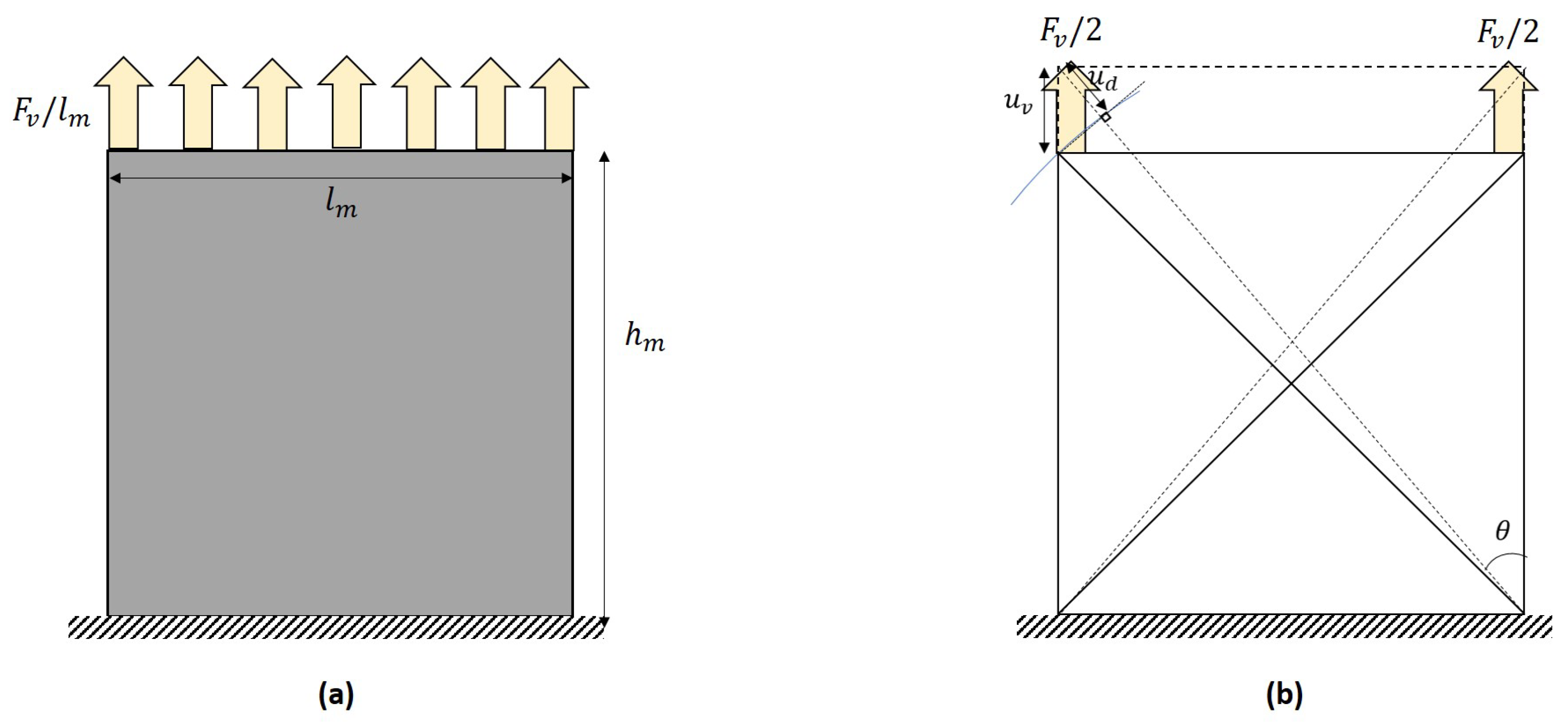
Appendix A.1. Vertical Loading

To determine the rigidity of the different struts of the DFM, consider the modeling of a wall of height ( h m ), width ( l m ), and thickness ( t m ) with a DFM element and an isotropic 2D medium, as shown in Figure 2. It is subject to a uniformly distributed vertical force ( F v ) that leads to a uniform displacement ( u v ) at the head of the wall. The wall has a Young modulus ( E m ) and a shear modulus ( G m ).
The rigidity of the DFM elements is determined by considering an equivalency of internal virtual work between the two situations.
The internal virtual work for the 2D medium is determined by the internal strain energy with the following equation:
W i n t = 1 2 σ = · ε = d V
In this equation, σ = is the stress tensor for the wall and ε = is the strain tensor. For the 2D medium with the current loading, the internal strain energy is as follows:
W i n t = 1 2 σ = · ε = d V = 1 2 σ ε V
where σ is stress, ε is strain, and V is the volume of the wall. Since the wall material is considered linearly elastic, the Hooke’s law is as follows:
σ = E m · ε
The strain due to the displacement, u v , is considered uniformly distributed along the height of the wall; therefore, we have the following:
ε = Δ h h = u v h m
Putting it all together, the internal virtual work can be calculated as follows:
W i n t = 1 2 E m · ε 2 · h m · t m · l m = 1 2 l m · t m · u v 2 h m
Consider the DFM element as shown in Figure 2b. The internal work for the element is determined by considering the elastic energy stored in all the struts in the configuration shown in the figure.
W i n t = 2 × W i n t , v + W i n t , d
In this equation, W i n t , v is the energy stored in a vertical strut, and W i n t , v is the energy stored in a diagonal strut. The deformation of the vertical strut is u v and the deformation of the diagonal strut is u d . The energy in the vertical and the diagonal strut can be written, respectively, as follows:
W i n t , v = 0.5 · F v · u v = 0.5 · K v · u v · u v = 0.5 · K v · u v 2
W i n t , d = 0.5 · F d · u d = 0.5 · K d · u d · u d = 0.5 · K d · u d 2
It is possible to determine the displacement, u d , in the function of u v as shown in Figure A1. Using the right-angled triangle is possible because of the assumption of small displacements.
Figure A1. Zoom in of a node of the DFM to see the connection between u v and u d .
Buildings 14 00768 g0a1
The value of u d knowing u v is u d = u v · cos θ with θ defined in Figure A1.
Therefore, the internal stored energy can be written as follows:
W i n t = 2 W i n t , v + W i n t , d = K v · u v 2 + K d · u d 2 = K v · u v 2 + K d · cos 2 θ · u v 2
The equivalence between the two models is expressed by the following equation, which is equivalent to Equation (3).
1 2 · E m · l m · t m · u v 2 h m = K v · u v 2 + K d · cos 2 θ · u v 2
The same strategy can be followed to find Equation (4).

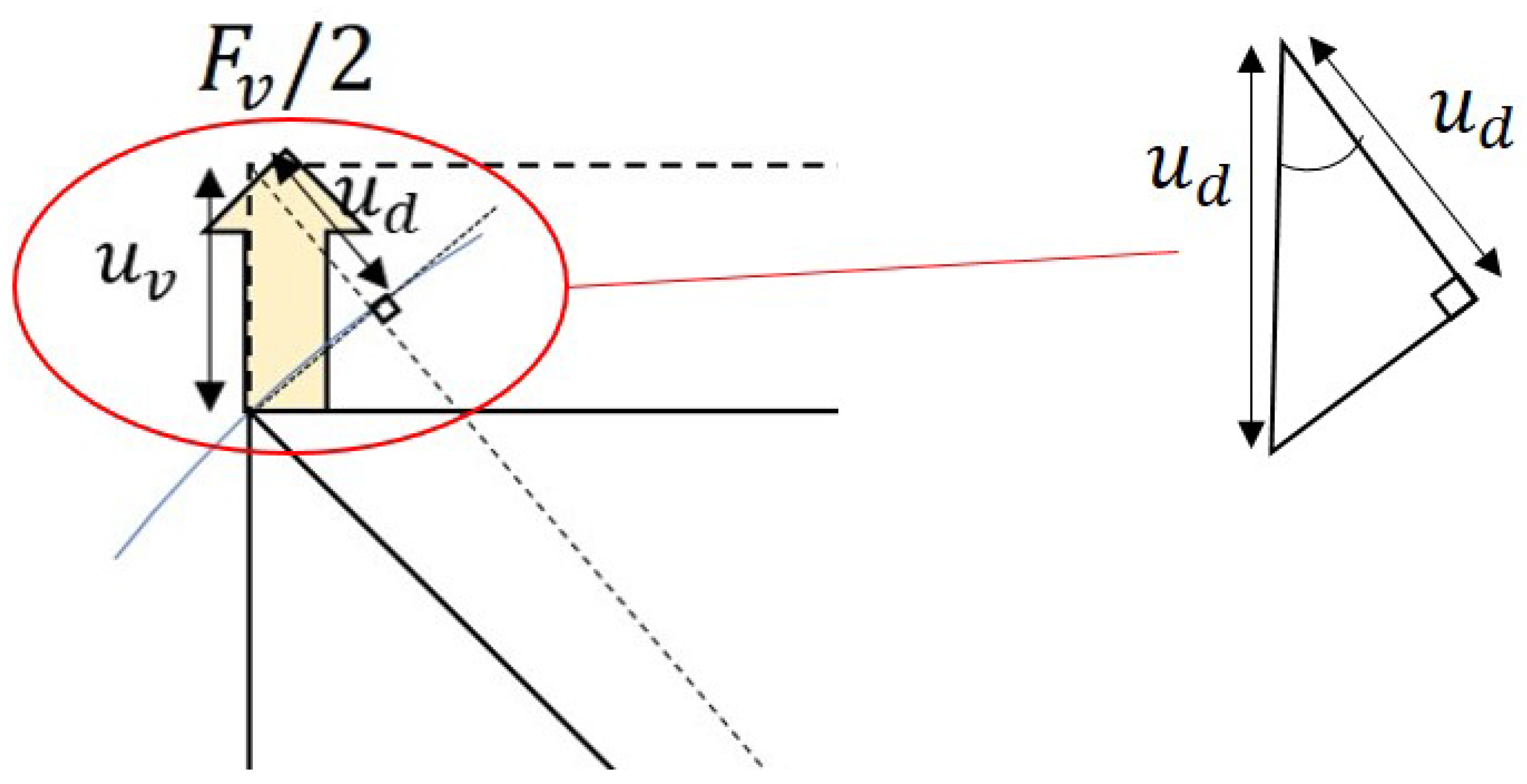
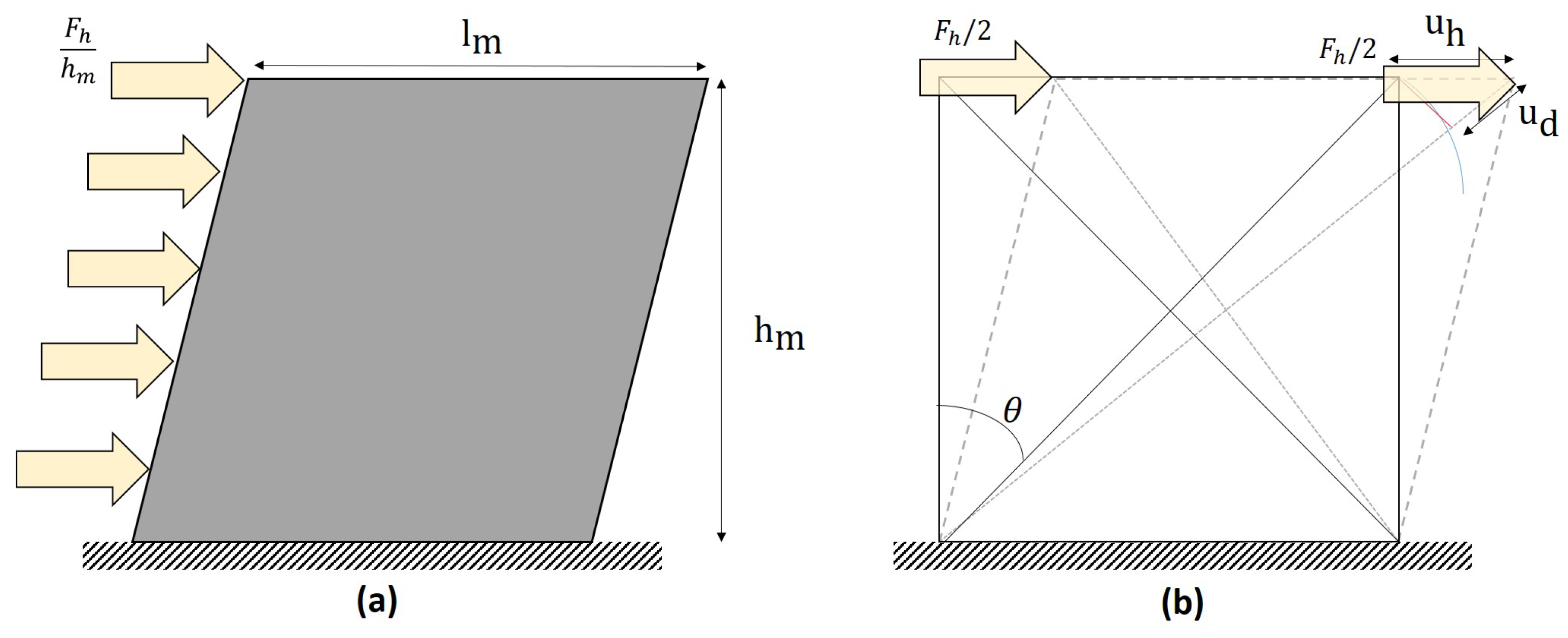
Appendix A.2. Shear Loading

The case of shear loading is shown in Figure A2 for the homogeneous and isotropic 2D medium and the DFM under shear loading.
Figure A2. Masonry element under shear loading modeled with (a) a homogeneous and isotropic medium; (b) the DFM (the deformed configuration is dashed).
Buildings 14 00768 g0a2
For the homogeneous and isotropic 2D medium, the internal energy is expressed by the following equation:
W i n t = 1 2 σ = · ε = d V = 1 2 G m · t m · l m · u h 2 h m
For the DFM, only the diagonal struts are deformed under shear load. This results in the following equation:
W i n t = 2 0.5 · F d ̲ · u d ̲ = 2 0.5 · K d u d · u h = K d · u h 2 · sin 2 ( θ )
The equivalence between the two models is expressed by the following equation, which is another way of writing Equation (5).
1 2 G m · t m · l m · u h 2 h m = K d · u h 2 · sin 2 ( θ )

References

  1. Zucchini, A.; Lourenço, P. A micro-mechanical model for the homogenisation of masonry. Int. J. Solids Struct. 2002, 39, 3233–3255. [Google Scholar] [CrossRef]
  2. Casolo, S. Modelling in-plane micro-structure of masonry walls by rigid elements. Int. J. Solids Struct. 2004, 41, 3625–3641. [Google Scholar] [CrossRef]
  3. Gambarotta, L.; Lagomarsino, S. Damage models for the seismic response of brick masonry shear walls. Part I: The mortar joint model and its applications. Earthq. Eng. Struct. Dyn. 1997, 26, 423–439. [Google Scholar] [CrossRef]
  4. Crisafulli, F.J. Seismic Behaviour of Reinforced Concrete Structures with Masonry Infills. Ph.D. Thesis, University of Canterbury, Christchurch, New Zealand, 1997. [Google Scholar]
  5. Panagiotakos, T.; Fardis, M. Seismic response of infilled RC frames structures. In Proceedings of the 11th World Conference on Earthquake Engineering, Acapulco, Mexico, 23–28 June 1996. Number 225. [Google Scholar]
  6. Combescure, D. Modélisation du Comportement Sous Chargement Sismique des Structures de Bâtiment Comportant des Murs de Remplissage en Maçonnerie. Ph.D. Thesis, Châtenay-Malabry, Paris, France, 1996. [Google Scholar]
  7. Pirsaheb, H.; Moradi, M.J.; Milani, G. A Multi-Pier MP procedure for the non-linear analysis of in-plane loaded masonry walls. Eng. Struct. 2020, 212, 110534. [Google Scholar] [CrossRef]
  8. Xu, H.; Gentilini, C.; Yu, Z.; Wu, H.; Zhao, S. A unified model for the seismic analysis of brick masonry structures. Constr. Build. Mater. 2018, 184, 733–751. [Google Scholar] [CrossRef]
  9. Shabani, A.; Kioumarsi, M. A novel macroelement for seismic analysis of unreinforced masonry buildings based on MVLEM in OpenSees. J. Build. Eng. 2022, 49, 104019. [Google Scholar] [CrossRef]
  10. Lagomarsino, S.; Penna, A.; Galasco, A.; Cattari, S. TREMURI program: An equivalent frame model for the nonlinear seismic analysis of masonry buildings. Eng. Struct. 2013, 56, 1787–1799. [Google Scholar] [CrossRef]
  11. EN1998-1; Eurocode 8: Design of Structures for Earthquake Resistance-Part 1: General Rules, Seismic Actions and Rules for Buildings. Technical Report; European Committee for Standardization: Brussels, Belgium, 2004.
  12. FEMA. Prestandard and Commentary for the Seismic Rehabilitation of Buildings (FEMA 356); Technical Report; Federal Emergency Management Agency: Washington, DC, USA, 2000. [Google Scholar]
  13. Tomazevic, M.; Weiss, P. A rational, experimentally based method for the verification of earthquake resistance of masonry buildings. Proceedings of Fourth US National Conference on Earthquake Engineering, Palm Springs, CA, USA, 20–24 May 1990; Volume 2, pp. 349–359. [Google Scholar]
  14. Tomazevic, M. The Computer Program POR, Report ZRMK; Technical Report; Institute for Testing and Research in Materials and Structures: Ljubljiana, Slovenia, 2016. [Google Scholar]
  15. POR2000. Structural and Seismic Calculation and Analysis of Masonry Structures. Newsoft. 2023. Available online: https://www.newsoft-eng.it/software/por-2000 (accessed on 10 February 2024).
  16. Braga, F.; Liberatore, D.; Spera, G. A computer program for the seismic analysis of complex masonry buildings. In Proceedings of the Computer Methods in Structural Masonry-4: Fourth International Symposium; CRC Press: Boca Raton, FL, USA, 1998; Volume 4, p. 309. [Google Scholar]
  17. Magenes, G.; Della Fontana, A. Simplified non-linear seismic analysis of masonry buildings. Proc. Br. Mason. Soc. 1998, 8, 190–195. [Google Scholar]
  18. Magenes, G. A method for pushover analysis in seismic assessment of masonry buildings. In Proceedings of the 12th World Conference on Earthquake Engineering, Auckland, New Zealand, 30 January–4 February 2000; Volume 42. [Google Scholar]
  19. Pasticier, L.; Amadio, C.; Fragiacomo, M. Non-linear seismic analysis and vulnerability evaluation of a masonry building by means of the SAP2000 V. 10 code. Earthq. Eng. Struct. Dyn. 2008, 37, 467–485. [Google Scholar] [CrossRef]
  20. Salonikios, T.; Karakostas, C.; Lekidis, V.; Anthoine, A. Comparative inelastic pushover analysis of masonry frames. Eng. Struct. 2003, 25, 1515–1523. [Google Scholar] [CrossRef]
  21. Rinaldin, G.; Amadio, C.; Macorini, L. A macro-model with nonlinear springs for seismic analysis of URM buildings. Earthq. Eng. Struct. Dyn. 2016, 45, 2261–2281. [Google Scholar] [CrossRef]
  22. Gambarotta, L.; Lagomarsino, S. Sulla risposta dinamica di pareti in muratura. In Atti del Convegno Nazionale “La Meccanica delle Murature tra Teoria e Progetto”; Pitagora Editrice: Messina, Italy, 1996; pp. 18–20. [Google Scholar]
  23. Gambarotta, L.; Lagomarsino, S. Computational models for the seismic response of damaging structures. In Proceedings of the US-Italian Workshop on Seismic Evaluation and Retrofit, New York, NY, USA, 12–13 December 1996; p. 45. [Google Scholar]
  24. Kolozvari, K.; Orakcal, K.; Wallace, J.W. New opensees models for simulating nonlinear flexural and coupled shear-flexural behavior of RC walls and columns. Comput. Struct. 2018, 196, 246–262. [Google Scholar] [CrossRef]
  25. Esmaeiltabar, P.; Vaseghi, J.; Khosravi, H. Nonlinear macro modeling of slender reinforced concrete shear walls. Struct. Concr. 2019, 20, 899–910. [Google Scholar] [CrossRef]
  26. Quagliarini, E.; Maracchini, G.; Clementi, F. Uses and limits of the Equivalent Frame Model on existing unreinforced masonry buildings for assessing their seismic risk: A review. J. Build. Eng. 2017, 10, 166–182. [Google Scholar] [CrossRef]
  27. Casolo, S.; Pena, F. Rigid element model for in-plane dynamics of masonry walls considering hysteretic behaviour and damage. Earthq. Eng. Struct. Dyn. 2007, 36, 1029–1048. [Google Scholar] [CrossRef]
  28. Casolo, S.; Pena, F. Modelling micro-structure aspects of masonry walls by a simplified approach. WIT Trans. Built Environ. 2003, 66, 10. [Google Scholar]
  29. Casolo, S. Macroscale modelling of microstructure damage evolution by a rigid body and spring model. J. Mech. Mater. Struct. 2009, 4, 551–570. [Google Scholar] [CrossRef]
  30. Caliò, I.; Marletta, M.; Pantò, B. A simplified model for the evaluation of the seismic behaviour of masonry buildings. In Proceedings of the 10th International Conference on Civil, Structural and Environmental Engineering Computing, Rome, Italy, 30 August–2 September 2005; Civil-Comp Press: Stirlingshire, UK, 2005; Volume 195. [Google Scholar]
  31. Pantò, B.; Raka, E.; Cannizzaro, F.; Camata, G.; Caddemi, S.; Spacone, E.; Caliò, I. Numerical macro-modeling of unreinforced masonry structures: A critical appraisal. In Proceedings of the Fifteenth International Conference on Civil, Structural and Environmental Engineering Computing, Prague, Czech Republic, 1–4 September 2015; Civil-Comp Press: Stirlingshire, UK, 2015. [Google Scholar]
  32. Caliò, I.; Pantò, B. A macro-element modelling approach of Infilled Frame Structures. Comput. Struct. 2014, 143, 91–107. [Google Scholar] [CrossRef]
  33. Pantò, B.; Caliò, I.; Lourenço, P.B. A 3D discrete macro-element for modelling the out-of-plane behaviour of infilled frame structures. Eng. Struct. 2018, 175, 371–385. [Google Scholar] [CrossRef]
  34. Pantò, B.; Rossi, P.P. A new macromodel for the assessment of the seismic response of infilled RC frames. Earthq. Eng. Struct. Dyn. 2019, 48, 792–817. [Google Scholar] [CrossRef]
  35. Turnšek, V.; Čačovič, F. Some experimental results on the strength of brick masonry walls. In Proceedings of the 2nd International Brick Masonry Conference, Stoke-on-Trent, UK, 12–15 April 1970; pp. 149–156. [Google Scholar]
  36. Mann, W.; Müller, H. Failure of Shear-Stressed Masonry: An Enlarged Theory, Tests and Application to Shear Walls. Proc. Br. Ceram. Soc. 1982, 30, 223–235. [Google Scholar]
  37. Decret, D. Numerical Model for the Assessment of the Seismic Vulnerability of Traditional Masonry Structures with Seismic Bands. Ph.D. Thesis, Université Grenoble Alpes, Grenoble, France, 2021. [Google Scholar]
  38. Anthoine, A.; Magonette, G.; Magenes, G. Shear-compression testing and analysis of brick masonry walls. In Proceedings of the 10th European Conference on Earthquake Engineering, Vienna, Austria, 28 August–2 September 1994; Volume 3, pp. 1657–1662. [Google Scholar]
  39. Gambarotta, L.; Lagomarsino, S. Damage models for the seismic response of brick masonry shear walls. Part II: The continuum model and its applications. Earthq. Eng. Struct. Dyn. 1997, 26, 441–462. [Google Scholar] [CrossRef]
  40. Caliò, I.; Marletta, M.; Pantò, B. A new discrete element model for the evaluation of the seismic behaviour of unreinforced masonry buildings. Eng. Struct. 2012, 40, 327–338. [Google Scholar] [CrossRef]
  41. Reyes, J.C.; Yamin, L.E.; Hassan, W.M.; Sandoval, J.D.; Gonzalez, C.D.; Galvis, F.A. Shear behavior of adobe and rammed earth walls of heritage structures. Eng. Struct. 2018, 174, 526–537. [Google Scholar] [CrossRef]
  42. Reyes, J.C.; Smith-Pardo, J.P.; Yamin, L.E.; Galvis, F.A.; Sandoval, J.D.; Gonzalez, C.D.; Correal, J.F. In-plane seismic behavior of full-scale earthen walls with openings retrofitted with timber elements and vertical tensors. Bull. Earthq. Eng. 2019, 17, 4193–4215. [Google Scholar] [CrossRef]
  43. Grange, S. ATL4S, a Tool and Language for Simplified Structural Solution Strategy; Technical Report; GEOMAS INSA-Lyon: Villeurbanne, France, 2016. [Google Scholar]
  44. Petrovčič, S.; Kilar, V. Seismic failure mode interaction for the equivalent frame modeling of unreinforced masonry structures. Eng. Struct. 2013, 54, 9–22. [Google Scholar] [CrossRef]
  45. Magenes, G.; Calvi, G.M. In-plane seismic response of brick masonry walls. Earthq. Eng. Struct. Dyn. 1997, 26, 1091–1112. [Google Scholar] [CrossRef]
  46. Sandoval Triana, J.D. Estudio Experimental y Modelación del Comportamiento de Estructuras en Adobe. Master’s Thesis, Uniandes, Bogotá, Colombia, 2018. [Google Scholar]
Figure 1. DFM’s schematic representation for in-plane analysis.
Buildings 14 00768 g001
Figure 2. Masonry element under a vertical load modeled with (a) homogeneous and isotropic medium; (b) the DFM (the deformed configuration is dashed).
Buildings 14 00768 g002
Figure 3. Modeling of a wall with four macro-elements.
Buildings 14 00768 g003
Figure 4. Force/displacement constitutive behavior of diagonal struts.
Buildings 14 00768 g004
Figure 5. Diagonal crack patterns of masonry walls with different slendernesses.
Buildings 14 00768 g005
Figure 6. (a) Masonry wall with an opening and a wood frame; (b) coarser possible mesh for DFM; (c) finer mesh using DFM.
Buildings 14 00768 g006
Figure 7. Wall with a reinforced opening with zoom on the reinforcement.
Buildings 14 00768 g007
Figure 8. Schematic view of the testing set-up by Anthoine et al. [38].
Buildings 14 00768 g008
Figure 9. Force/displacement curves for the tests by Anthoine et al. [38]: (a) experimental results for the high wall; (b) experimental results for the small wall; (c) DFM numerical results for the high wall; (d) DFM numerical results for the small wall. The dashed red lines are the experimental envelope curves.
Buildings 14 00768 g009
Figure 10. (a) Scheme of the walls tested by Reyes [42]; (b) the wall as it is modeled in ATL4S [43].
Buildings 14 00768 g010
Figure 11. (a) Experimental cyclic response of the adobe wall [41]; (b) numerical cyclic response. The red dashed line is the envelope of the experimental curve, the continuous line is the DFM result.
Buildings 14 00768 g011
Figure 12. (a) Trilinear force/displacement law for the diagonal struts; (b) results with the trilinear model. The red dashed line is the envelope of the experimental curve. The continuous line is the DFM result.
Buildings 14 00768 g012
Figure 13. (a) Used lintels modeling for Figure 10, Figure 11 and Figure 12; (b) modeling with long lintels; (c) modeling with short lintels.
Buildings 14 00768 g013
Figure 14. Push-over curves of the three cases in Figure 13.
Buildings 14 00768 g014
Table 1. Mechanical properties of the two URM piers.
Stiffness
Young modulus a E m 2.1 GPa
Shear modulus a G m 420 MPa
Shear strength
Tensile strength b f t 0.345 MPa
Cohesion cc0.23 MPa
Coefficient of friction c μ 0.43
Masonry density a ρ m 1750 kg·m−3
Brick length c L b 120 mm
Brick height c H b 55 mm
a From Gambarota and Lagomarsino [39]. b The tensile strength is taken as 1.5 times the cohesion, as suggested by Petrovčič et al. [44]. c From Magenes and Calvi [45].
Table 2. Calculated values of the parameters of the hysteresis.
α β γ
High wall0.9885–0.990.820.6
Small wall0.9438–0.94460.530.3
Table 3. Mechanical properties for the unreinforced adobe walls with openings.
Stiffness
Young modulus b E m 200 MPa
Poisson’s ratio b ν m 0.15
Shear Strength
Tensile strength a f t 27.5 kPa
Cohesion ac15 kPa
Friction coefficient a μ 0.86
Masonry density a ρ m 1850 kg·m−3
Properties of Lintels
Young modulus c E l 9 GPa
Poisson’s ratio c ν l 0.2
Section b A l 15 × 15 cm2
Lintel density c ρ l 700 kg·m−3
a From tests performed on adobe prisms and the mortar by Reyes et al. [42]. b From the data given by Reyes et al. [41,42]. c From Sandoval et al. [46], who worked on this experimental campaign.
Disclaimer/Publisher’s Note: The statements, opinions and data contained in all publications are solely those of the individual author(s) and contributor(s) and not of MDPI and/or the editor(s). MDPI and/or the editor(s) disclaim responsibility for any injury to people or property resulting from any ideas, methods, instructions or products referred to in the content.

