Article

Optimization Analysis of Partition Wall Support Scheme of Multi-Arch Tunnel

1
China Communications Second High Way Engineering Bureau Co., Ltd., Xi’an 710119, China
2
Shaanxi Key Laboratory of Geotechnical and Underground Space Engineering, Xi’an 710055, China
3
School of Civil Engineering, Xi’an University of Architecture and Technology, Xi’an 710055, China
4
China Railway 20th Bureau Group Co., Ltd., Xi’an 710016, China
*
Author to whom correspondence should be addressed.
Buildings 2024, 14(2), 490; https://doi.org/10.3390/buildings14020490
Submission received: 18 November 2023 / Revised: 28 January 2024 / Accepted: 6 February 2024 / Published: 9 February 2024
(This article belongs to the Special Issue Safety and Optimization of Building Structures)

Abstract

:
With the fast progress of infrastructure projects, super-large cross-section projects are constantly emerging, and, therefore, engineering challenges and problems are increasing. Taking the triple-arch tunnel project in the turn-back line section of Santunbei Station in Urumqi Metro Line 1# as a case study, this research applied numerical simulation software Midas GTS/NX 2022 for the analysis of tunnel force and deformation in triple-arch cross-sections under different support forms of partition wall. Following the optimization of the support design of the mixed partition wall to a single straight wall, the following analytical results were obtained: surface settlement was decreased by 21.15% at the original cross-section; maximum values of principal stress and displacement of partition wall were decreased by 6.73 and 10.64%, respectively; and corresponding values for initial support structure were decreased by 21.47% and 54.74%, respectively. Meanwhile, combined with comparative analysis of engineering measurement and numerical simulation results, surface settlement and vault deformation were found to be similar to the optimized simulation results, which not only verified the reliability of simulation results but also ensured the safe and smooth construction of the project, greatly improving construction efficiency and saving construction time and cost.

1. Introduction

With the rapid expansion of urban railways, the construction of subway tunnels has progressively revealed the evolution features of enormous burial depth, large sections, and big spans [1,2,3,4,5]. The increase in the number of large-section tunnels has also created some engineering challenges, such as surrounding rock deformation [6,7,8], support structure instability [9,10,11], and lining cracking [12,13,14], which have seriously threatened project construction and operation safety. Especially because of the complex structure, large span, and cumbersome working procedures, multi-arch tunnels are prone to large surrounding rock distortion and supporting structure instability. To guarantee the construction and operation safety of multi-arch tunnels, many researchers have investigated practical engineering problems using numerical calculations, theoretical analyses, laboratory tests, site monitoring, and other research methods [15,16,17,18,19]. To ensure the building process security of large-span shallow-buried tunnels, Jin et al. (2015) investigated the best excavation process and restriction technology for pilot tunnels by combining numerical simulations with field monitoring [20]. Finally, the experimentally obtained data from the real tunnel were applied to illustrate how effective the models were. Song et al. (2020) took the engineering background of a section of Santunbei Turning Line of Urumqi Metro Line 1# as the case study and analyzed the effect of the tunnel construction method on the surrounding rock and supporting structure cracking and instability failure mode [21]. Chen et al. (2019) investigated the asymmetric mechanical properties of deep-buried carbonaceous phyllites and their effects on the asymmetrical mechanical behaviors of supporting structures in actual engineering [22]. According to actual field data along with the obtained numerical simulation results, it could be deduced that surrounding rock asymmetrical distortions and secondary lining cracking were caused by the combined effect of layered soft stone and shear action along the foliation. Yang et al. (2019) performed large-scale model tests and numerical modeling to explore deformation convergence and tunnel surrounding rock breakdown features in deep-buried mixture strata [23]. They found that surrounding rock deformation consisted of the following two components: immediate and persistent creep deformations. In the meantime, the findings of numerical modeling revealed that the damage rule of the tunnel’s surrounding rock was governed by both stress and lithological characteristics, which was extremely consistent with experimental results. Liu et al. (2020) took the Badaling Great Wall station in Beijing as the research object, selected a typical monitoring section in the super-span transition section of the tunnel, and methodically monitored deformation and stress between surrounding rock and supporting structures [24]. Their findings revealed that deformations and stresses between the surrounding rock and tunnel lining were directly related to construction processes, geophysical conditions, and super-span tunnel positions. Considering the excavation compensation method (ECM), He et al. (2023) revealed model experiments to investigate the control effects of various anchor cable support approaches in the initial support phase of a large-span tunnel. Their findings indicated that the negative Poisson’s ratio (NPR) of the anchor cable support was better suited to the initial support phase of super-large-span tunnels compared to traditional anchor cable support. Timely implementation of stress compensation was found to be essential in effectively controlling the surrounding rock’s potential instability or failure [25].
Excavation and support methods have been found to significantly affect surrounding rock deformation and stability. An appropriate excavation and support method is of utmost significance to surrounding rock stability and construction safety [21,26,27,28,29,30]. Wang et al. (2019) developed a highly durable support method for confined concrete (CC) arches and applied numerical calculations and laboratory experiments to investigate limiting bearing capacity and inner force distributions [31]. On the basis of the aforementioned results, an experimental test was performed in Liangjia Mine and it was found that CC arch support was more suitable for controlling surrounding rock deformation than the U-shaped steel arch support. In view of the control problem of the surrounding rock of the large section chamber under the 1200 m deep goaf, Xie et al. (2019) developed a comprehensive control method employing a powerful anchor bolt (cable) support, thick reinforced concrete wall pouring, and full section pressure-regulating grouting behind the wall and determined supporting mechanisms according to chamber’s surrounding rock stress relief [32]. Project practice revealed that the surrounding rock deformation peak was only 50 mm 4 years after construction completion, indicating that the developed method had realized long-term valid control with no refurbishment after a large section chamber supporting under 1200 m depth goaf. Chen et al. (2019) conducted a case study on the big deformation mechanism and supporting methods of the Maoxian tunnel in Sichuan Province, China, located in the center of the region, and found that severe deformation occurred in broken phyllite under high-ground stresses [33]. Large deformations occurred due to the combined action of high geo-stress and low self-stability of carbonaceous phyllite, and single and double initial support schemes were sequentially applied to limit squeezing deformation. Their findings revealed that a single initial support scheme could not guarantee the tunnel’s long-term safety, while a double initial support scheme effectively limited substantial deformation and rheological effects due to broken phyllite under high-geo-stress conditions. Li et al. (2021) developed a microseismic (MS) monitoring system and performed numerical modeling using the discrete element technique (DEM) for the evaluation of rock mass stability under high-geo-stress underground powerhouse caverns undergoing excavation [34]. Bian et al. (2023) studied the excavation unloading effect and determined the mechanical behavior of rock excavation [35]. Their research introduced an excavation compensation method formulated from a mechanical perspective. An excavation equivalent stress compensation test method was developed for the validation of the significant role of compensation stress in the prevention of rock cracking, reduction in tensile stress areas in the arch, increase in peak bearing capacity, and improvement in plastic deformation capacity. To solve the problems of field construction, He et al. (2023) took the Beishan No. 2 Tunnel as the case study and developed a fine 3D numerical model along with an on-site monitoring scheme for the tunnel. Using indoor tests and on-site monitoring, the mechanical responses of shallow super-large-span tunnels were explored, and construction scheme optimization results were systematically described by numerical simulation [36].
Recently, tunnel construction has entered a rapid development era, which has resulted in more complicated large-span and large-section tunnel construction processes and force states of support structures. Tunnel stability under various middle partition wall support schemes is yet to be completely understood. To solve the concentrated stress problem at the abrupt section of curved and straight walls in Urumqi Metro Line 1#, the mixed-support scheme of straight and curved walls in the original design scheme was optimized to a single straight wall. This research applied Midas GTS/NX software for the simulation and investigation of ground settlement, middle partition wall, and support structure under various schemes of partition wall support and summarized the forces and deformation features of the tunnel with different characteristic sections in construction. Meanwhile, by combining numerical modeling and on-site monitoring results under a single-wall support scheme, the settlement of the surface and tunnel vault were analyzed. Surface settlement simulated and measured deformation peaks of the triple-arch tunnel were 7.81 and 4.85 mm, respectively. The corresponding values of the main hole vault’s settlement were 8.60 mm and 10.63 mm, respectively, which guaranteed tunnel construction safety. Furthermore, numerical simulation variation law was found to be basically consistent with field monitoring, which further verified the validity of the selected partition wall support project. Numerical simulation results have been well employed in the actual project, improving construction efficiency and decreasing construction costs. Research results had a certain guiding significance for multi-arch tunnel design optimization and construction safety.

2. Project Description

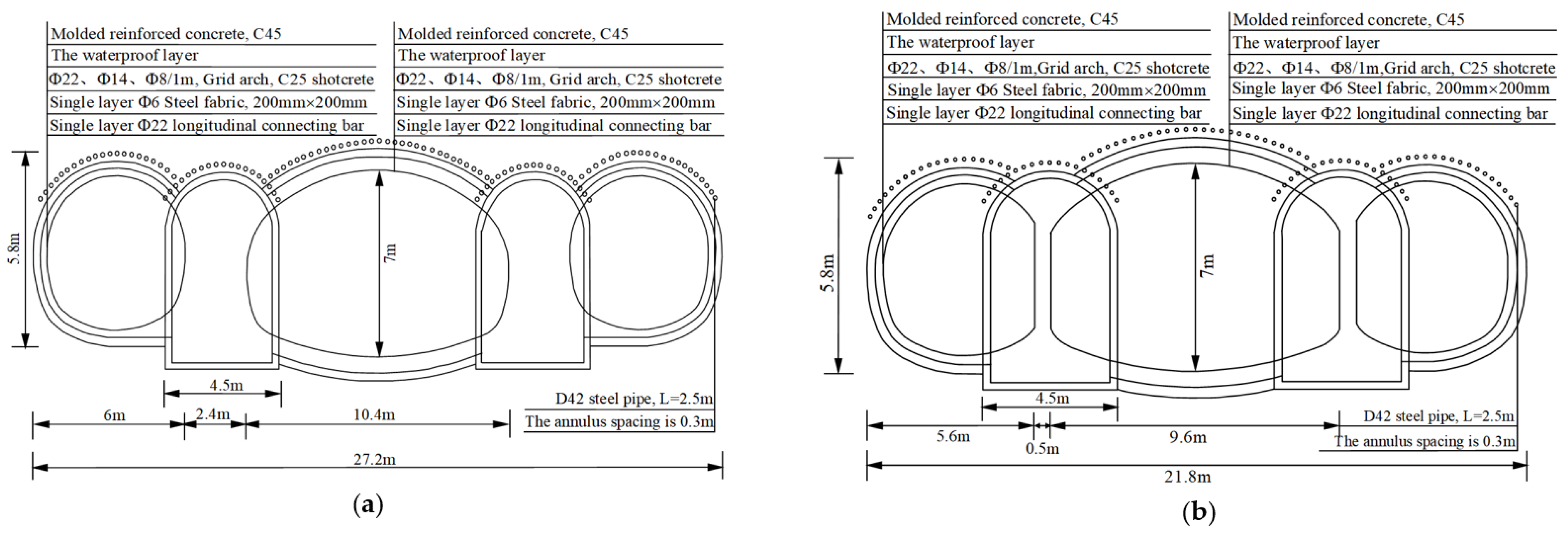
2.1. Tunnel Overview

The tunnel mileage of the turn-back line section of Santunbei Station in Urumqi Metro Line 1# is CDK0+129.75~CDK0+211.98, with 82.23 m length and a maximum excavation area of 178.00 m2, which belongs to super-large-span-section tunnel. The tunnel has a four-line triple-arch cross-section, including the main hole, side hole, and guide hole. The side hole and main hole heights are 5.8 and 7 m, respectively. Furthermore, the tunnel partition wall is in a mixed-support form of straight and curved walls. The curved wall section length is 42.43 m, and the guide hole, side hole, and main hole spans are 4.5, 6, and 10.4 m, respectively. The straight-wall section’s length is 39.80 m, and the guide hole, side hole, and main hole spans are 4.5, 5.6, and 9.6 m, respectively. Different support structure cross-sections are illustrated in Figure 1.

2.2. Geological Overview

The tunnel site is mainly situated in a denuded hilly area with high topographic relief, and the vault buried depth is in the range of 11~23 m. Overlying soil layers are Triassic miscellaneous fill, strongly–moderately weathered sandstone, strongly–moderately weathered mudstone, and moderately weathered conglomerate, with locally distributed silty clay. The thickness of various lithological strata, which are interbedded with each other, is uneven. The tunnel site and stratigraphic section are presented in Figure 2.
Based on geotechnical investigation data of Metro Line 1# tunnel site area and laboratory geotechnical experiment results, the physical and mechanical parameters of various strata are summarized in Table 1.

2.3. Analysis of Engineering Issues

The tunnel partition wall was a mixed-support form of straight and curved walls, and concentrated stress occurred at the partition wall’s abrupt section. This was the main reason that caused the cracking of the supporting structure and led to the reduced integrity and bearing capacity of the partition wall. Meanwhile, mixed-support scheme construction was more complicated than single straight wall, which was not conducive to engineering construction. Furthermore, construction period extension can easily cause engineering safety problems. Hence, the partition wall support scheme should not only meet the tunnel’s stability and safety during construction but also guarantee the tunnel project’s construction efficiency. According to the above engineering issues, this research optimized mixed partition wall support form in the original design scheme into a single straight wall, as shown in Figure 3c. Hence, the surface settlement, the deformation and force characteristics of the partition wall, and the initial support structure under the two support schemes were analyzed and discussed via modeling.

3. Numerical Simulation

The 3D numerical model was constructed using Midas GTS/NX numerical calculation software. This simulation explored the deformation distribution laws of the surface, middle partition wall, and initial support structure in each construction stage of the triple-arch tunnel, which obtained the comparative results that used a mixed partition wall and a single straight-wall support scheme, respectively.

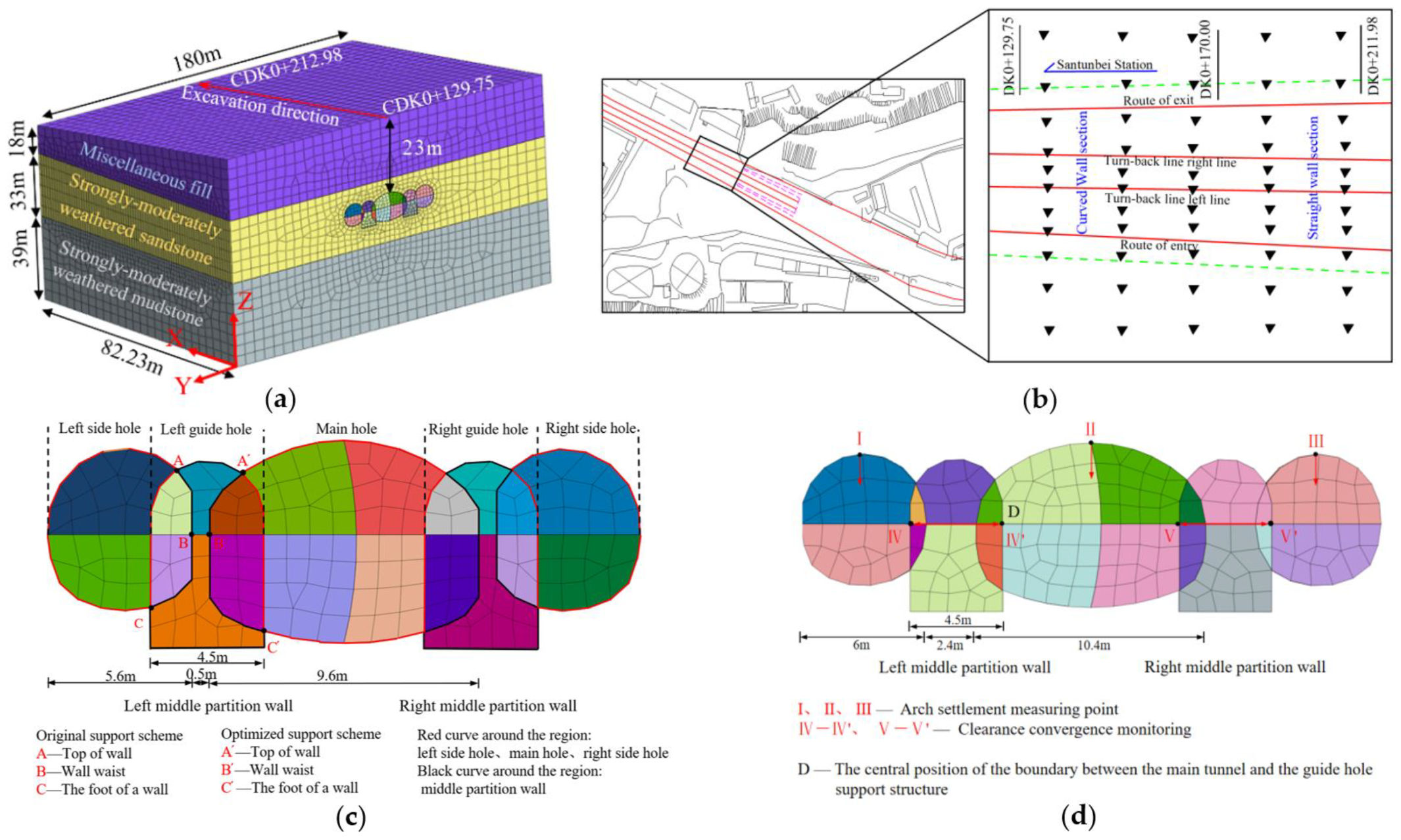
3.1. Model and Parameters

The tunnel excavation influence range was properly considered to guarantee the reliability and effectiveness of the numerical calculation result. According to the “Code for Design of Railway Tunnels”, the model length was 180.0 m along the Y direction, 82.23 m along the X direction, and 100 m along the Z direction, and the overburden value was 11~23 m. The model was fixed in both vertical and horizontal directions at the bottom, which prevented excessive displacement during the simulation. Furthermore, vertical boundaries were constrained along a horizontal direction to prevent any potential distortion of the results [37]. The mesh size of the tunnel and initial support structure was 1.0 m, and that of the surrounding rock was 4.0 m. Hence, the mesh number was 164,335, and the node number was 904,520. At the same time, the friction behavior of the two interfaces was simulated by setting interface element node coupling in the model to reflect the interaction between the surrounding rock and partition wall and ensure the consistency and coordination of the stress and deformation of the surrounding rock and the partition wall. The load was mainly considered as surrounding rock weight. Figure 3a shows a triple-arch tunnel model. To understand the dynamics of surrounding rock, supporting structures, and buildings around the site, the monitoring information should be analyzed in real time, predicted, and fed back to realize information construction. In excavation and support processes, the stress and deformation of the stratum and support structure were strictly monitored to guarantee tunnel construction safety. Surface settlement, partition wall, and measuring points for surrounding rock deformation are illustrated in Figure 3b–d.
According to geotechnical data and laboratory geotechnical experiment results and considering the “Code for Design of Composite Structures”, model material parameters were determined, as summarized in Table 2. Strata were modeled using entity units with the Mohr–Column model; the initial support was modeled using plate elements with elastic behavior, and the middle wall was modeled using entity units with elastic behavior [3].

3.2. Construction Scheme

Considering the tunnel construction stability, the side and guide holes were excavated through the step method, and the main hole was excavated using the controlled rock deformation (CRD) method. Firstly, bilateral guide holes were excavated, and the distance between the palm surfaces of the two guide holes was 30 m. Then, side holes were excavated for a certain distance, and the distance between the palm surfaces of the two side holes was 15 m. Finally, the main hole was excavated, and the spacing between the palm surfaces of adjacent steps in each hole was 5 m. Specific construction processes were as follows: ① excavation of the right guide hole; ② excavation of the left guide hole; ③ construction of the right middle partition wall; ④ construction of the left middle partition wall; ⑤ excavation of the right side hole; ⑥ construction of the right hole’s initial support structure; ⑦ excavation of the left side hole; ⑧ construction of the left hole’s initial support structure; ⑨ excavation of the main hole; ⑩ construction of the main hole’s initial support structure, as illustrated in Figure 4.

3.3. Analysis of Simulation Results

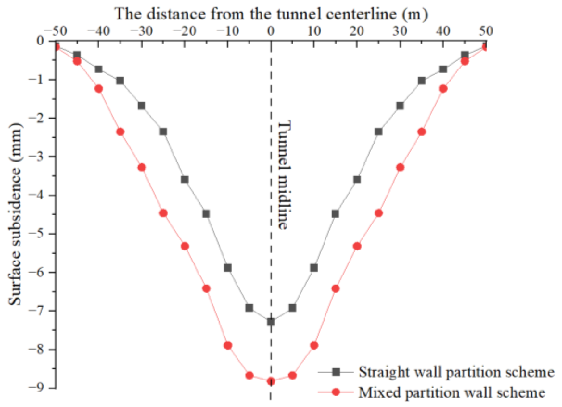
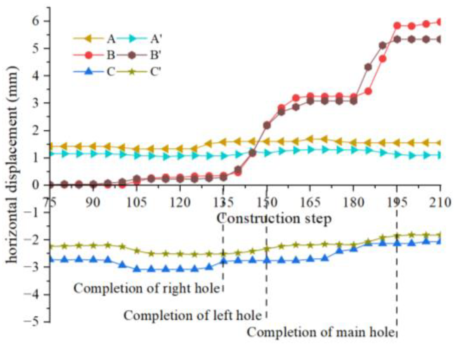
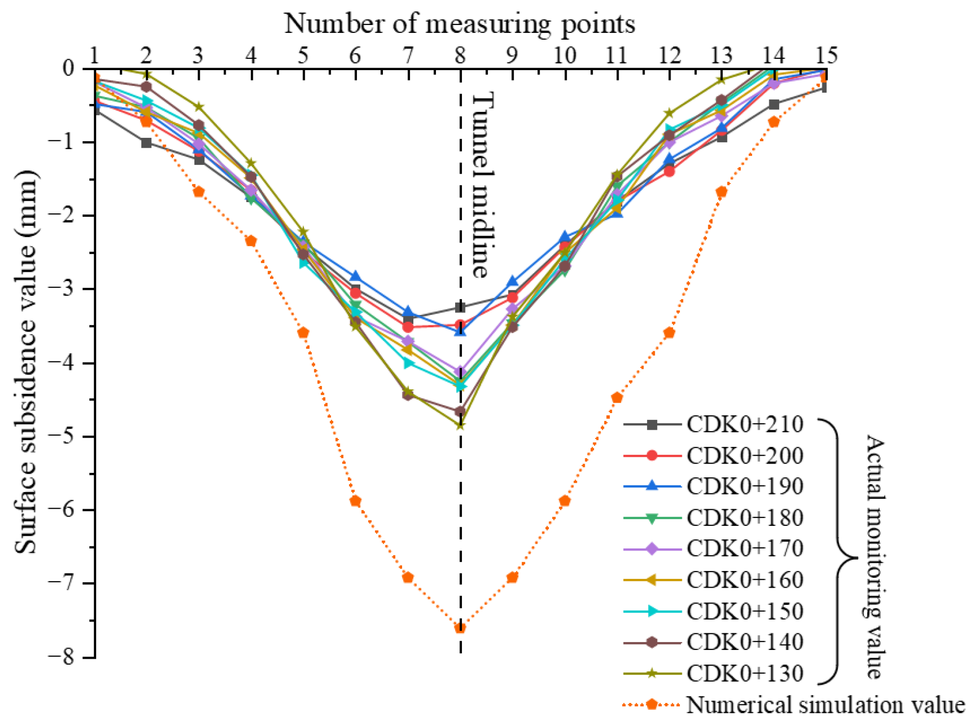
3.3.1. Ground Settlement

Figure 5 shows stratum overall settlement deformation under two support schemes (“+” and “−“ represent positive and negative shifts to the “Z-axis”, respectively).
Overall, stratum deformation under two support schemes showed obvious symmetrical distribution properties after the excavation was accomplished. However, the peak stratum deformation under the mixed-support scheme was larger, and the maximum settlement occurred at the main hole’s vault in a variable cross-section position (CDK0+180), with a maximum value of 8.82 mm. The reason for this was that excavation disturbance caused stress concentration at variable cross-section position, and the forces and deformations of the surrounding rock and supporting structure were larger. With stress transfer, the overlying soil layer settlement and deformation were increased. Under the influence of stratum distribution difference, the maximum stratum settlement occurred at the CDK0+130 section under a single straight-wall support form, with the deformation peak reducing by 13.77%.
Variable cross-section position (CDK0+180) settlement results under two support schemes were found based on the stratum settlement measurement points shown in Figure 3b, and deformation differences were further compared and analyzed, as illustrated in Figure 6. It was found that due to the unloading disturbance caused by excavation, stratum settlement deformation was the largest in the middle of the excavation area, and deformation was steadily diminished as the distance of the measuring point from the tunnel midline was increased. Ground settlement under two support modes was symmetrically distributed along the tunnel’s midline, and disturbance response areas on both sides were distributed within 50 m from the main hole’s axis. Combined with the tunnel excavation process analysis, the upper soil began to settle and accumulate due to the guide hole’s excavation disturbance. With the middle wall implemented and acting as a support for the upper soil, ground settlement was gradually stabilized. The ground settlement value of this stage under the two schemes accounted for 39.75 and 40.18% of the total settlement, respectively. Based on the partition wall’s supporting effect, ground settlement in the side hole’s construction stage slowly increased, and cumulative deformation increment decreased. The peak value of ground settlement in this stage was increased by 10.35% and 8.49% of the total settlement, respectively. The overlying soil disturbance was significantly increased during the main hole’s construction, and the ground settlement accumulated rapidly, especially at the main hole’s arch top. After the construction was completed, the maximum ground settlements under the two support schemes were 8.82 and 7.28 mm, respectively. Maximum settlement under the optimized support scheme was 21.15% lower than that of the original scheme. The obtained results showed that the single straight-wall support structure not only ensured the stratum’s stability but also simplified the construction process, which was conducive to safe and rapid construction.

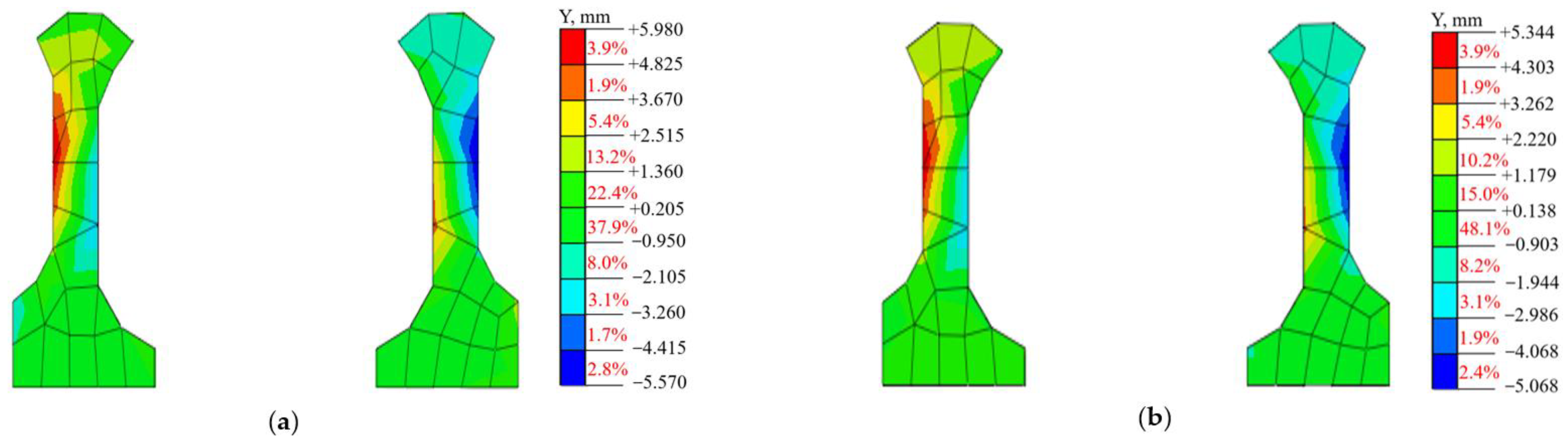
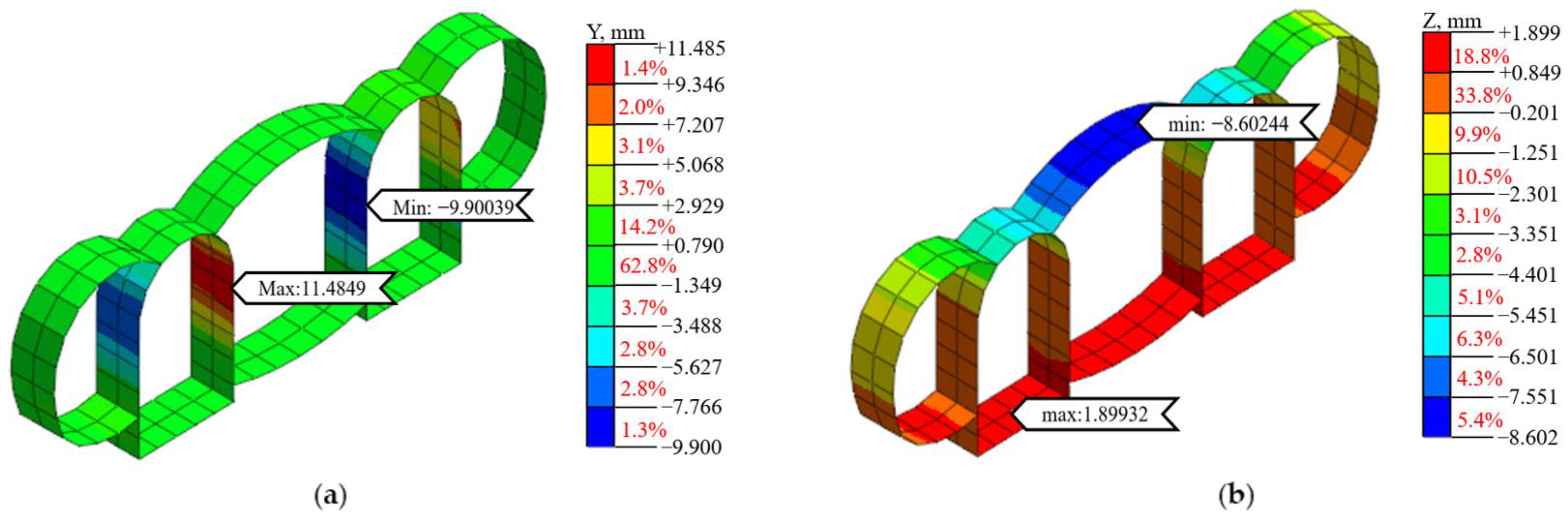
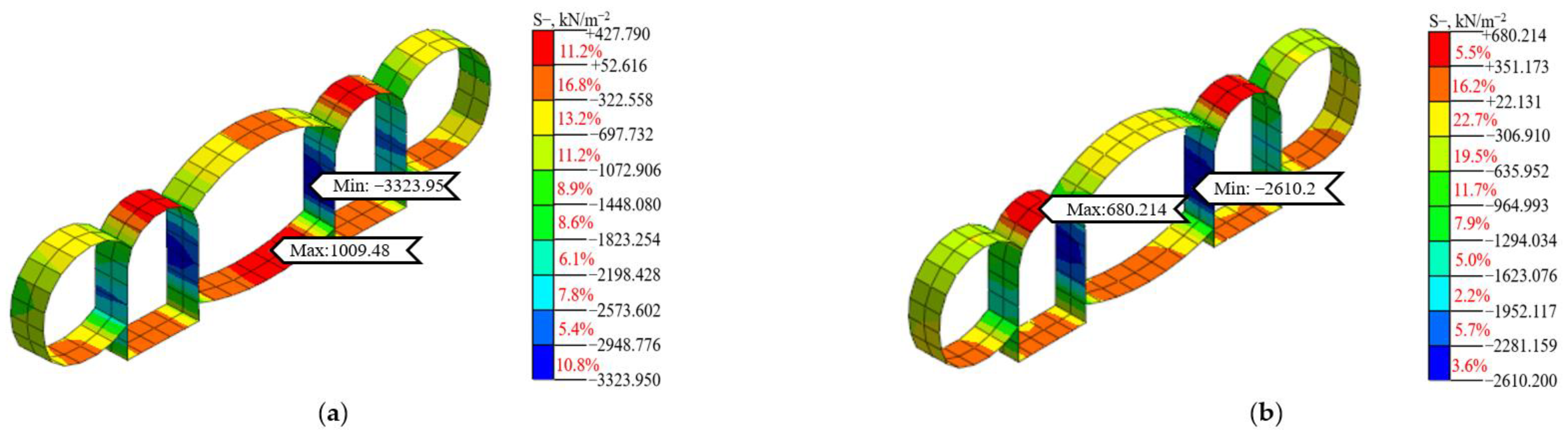
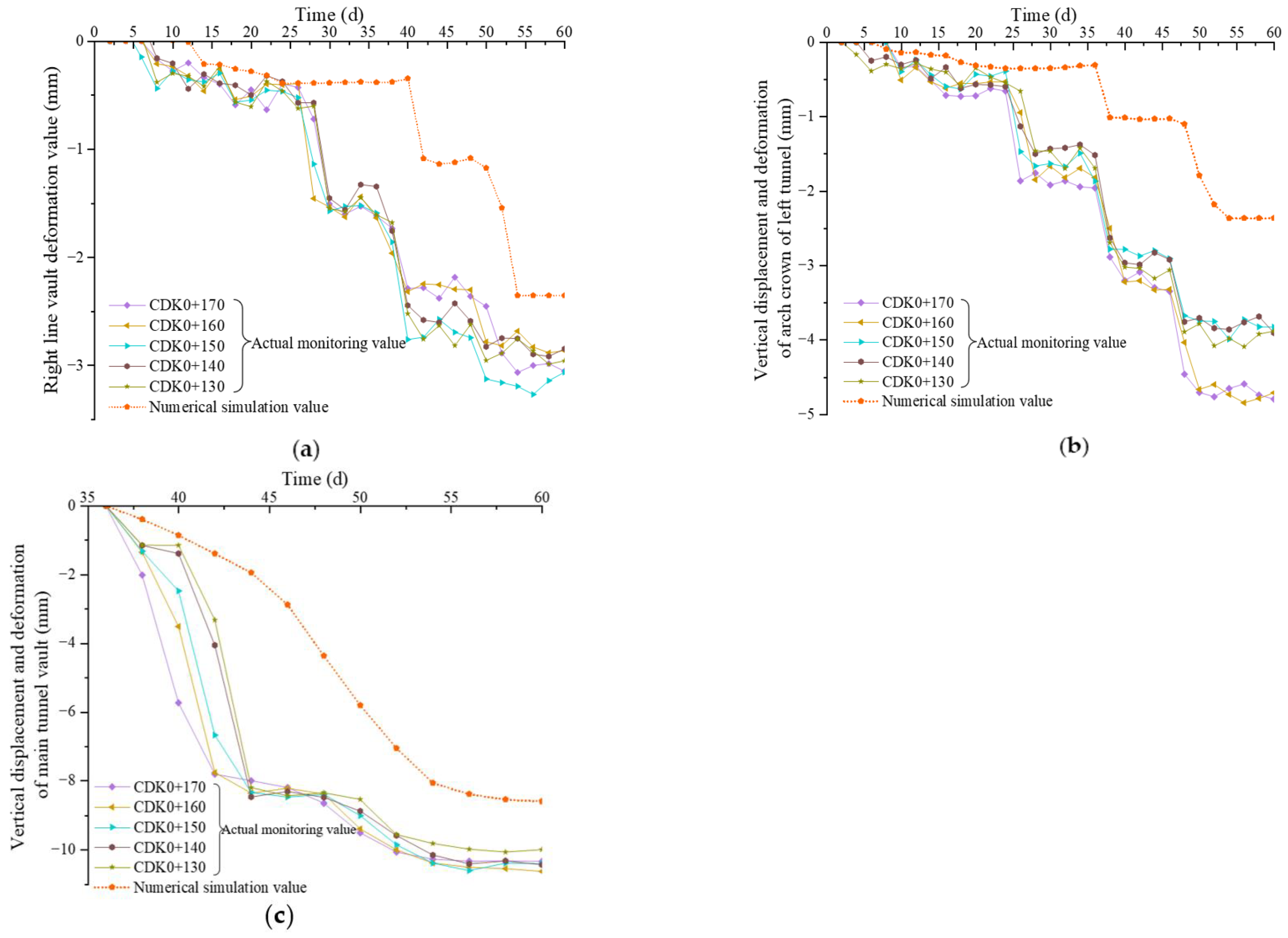
3.3.2. Middle Partition Wall’s Deformation and Force

(1) Deformation analysis
The partition wall’s overall horizontal displacement deformation under the two support schemes is shown in Figure 7 (“+” and “−“ represent positive and negative shifts to the “Y-axis”, respectively). The partition wall’s displacement peak under the mixed-support scheme was larger, which occurred at CDK0+156 section wall’s waist with a maximum value of 5.98 mm. The partition wall’s maximum displacement also occurred at the CDK0+156 section under a single straight-wall support scheme, with a displacement peak reducing by 10.64%. Based on geological investigation data, it was found that the stratum was loose at the CDK0+156 section location with lower stability and strength, and the partition wall played a supporting role and bore greater pressure due to excavation disturbance, continuously increasing the partition wall’s displacement.
The middle partition wall is a unique supporting component in multi-arch tunnels, and its displacement is intimately related to the tunnel’s stability. Based on the partition wall’s overall displacement distribution characteristics, the CDK0+156 section was selected for the key analysis. Figure 8 illustrates the partition wall’s displacement under two support schemes. It was found that the partition wall’s support structure played a supporting role in surrounding rock after the tunnel excavation and mainly bore vertical load, resulting in smaller horizontal displacements at the partition wall top and corner and larger in the wall’s waist adjacent to the side hole. Meanwhile, the left partition wall’s displacement was higher than that of the right partition wall due to the stratum distribution difference.
To further derive partition wall displacement variation law during construction, the left partition wall’s displacement results at the section were sorted out according to the measuring points illustrated in Figure 3c, and the results are shown in Figure 9. It was found that before the excavation of the two side holes, the partition wall had already borne the overlying soil layer vertical load, producing a small horizontal displacement. When the right hole was excavated (the 95th construction step), the partition wall’s horizontal displacement was gradually increased due to the biased pressure caused by unbalanced horizontal thrust. At this stage, the partition wall’s maximum displacement under two support schemes was increased by 0.36 and 0.28 mm, respectively. When the left hole was excavated (the 135th construction step), soil removal on the partition wall’s left side caused the partition wall’s stress to release so that the partition wall generally moved to the left side, and the horizontal displacement deformation rate at the wall’s waist was the largest. With the initial support structure implemented and playing a supporting role, the displacement deformation rate at the wall’s waist gradually decreased and tended to be stabilized. At this stage, the partition wall’s maximum horizontal displacements under two support schemes were increased by 2.97 and 2.85 mm, respectively. When the main hole was excavated (the 180th construction step), the pressure generated by the upper soil layer on the partition wall increased so that the displacement deformation rate at the wall’s waist was continuously increasing. By using the initial support structure as a support, the wall’s waist displacement deformation rate gradually decreased and tended to be stabilized. At this stage, the partition wall’s maximum horizontal displacements under two support schemes were increased by 2.65 and 2.21 mm, respectively. The results showed that the partition wall’s horizontal displacement supported by the single straight wall was smaller than that of the mixed-support scheme.
(2) Force analysis
The partition wall’s overall primary stress distributions under two support schemes are illustrated in Figure 10. After the construction was completed, the partition walls under two support schemes were mainly subjected to vertical pressure. However, the wall under the mixed-support scheme was subjected to greater pressure; stress peak occurred at variable cross-section (CDK0+180) waists with the maximum value of 965.35 kPa. The reason was that the cross-section spanning from the curved wall to the straight wall presented a sudden change in form, which caused the generation of the partition wall’s stress. Under the effect of stratum settlement difference, the partition wall’s maximum stress occurred at the CDK0+130 section under a single straight-wall support form with a maximum stress reduction of 6.73%.
Previous deformation analyses have shown that the mixed-support scheme had stress concentration at the abrupt section of the partition wall. This was the primary reason for the support structure cracking and the deterioration of the bearing capacity and integrity of the partition wall. After single straight-wall support scheme optimization, the overall force of the partition wall was uniform, which could not only effectively solve the stress-concentration problem but also improve construction efficiency. It helped ensure tunnel construction stability and safety.

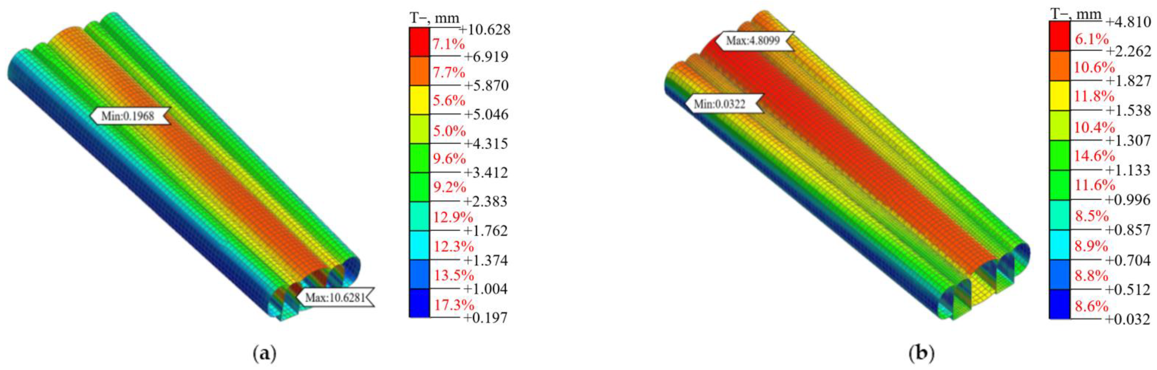
3.3.3. Initial Support Structure Deformation and Force

(1) Deformation analysis
The initial support structure’s overall deformations under two support schemes are illustrated in Figure 11. The initial support structures under the two support schemes showed large deformation distribution characteristics in the main hole and small deformation distribution characteristics in the two side holes after the excavation was completed. However, the deformation under the mixed-support scheme was larger, and the maximum deformation occurred in the CDK0+210 section, with a maximum value of 10.63 mm. Due to stratum settlement and partition wall support form differences, the maximum deformation occurred at the CDK0+130 section under a single straight-wall support scheme, with the deformation peak reducing by 54.74%.
The initial support structure is critical to strengthen and protect the stability of the surrounding rock during the tunnel’s construction. Therefore, taking the section with the largest deformation as a typical section, the structural deformation was further analyzed from the transverse deformation and vertical deformation of the initial supporting structure. Since the initial support structure mainly bore the vertical load, the maximum lateral deformation occurred at the main hole–left guide holes’ junction, and the maximum vertical deformation took place at the main hole’s vault. However, the initial support structure’s maximum transverse deformation under the mixed-support scheme occurred at the CDK0+200 section, with a maximum value of 12.52 mm. The initial support structure’s maximum transverse deformation under the straight-wall support scheme occurred at the CDK0+210 section with a deformation peak reduction of 8.31%. The initial support structure maximum vertical deformation under a mixed-support scheme occurred at the CDK0+130 section with a maximum value of 9.59 mm. The initial support structure maximum vertical deformation under the straight-wall support scheme occurred at the CDK0+150 section, with a deformation peak reduction of 10.32%. The typical sections under the straight-wall support form are presented in Figure 12.
According to the transverse deformation distribution features, the initial support structure at the typical section shown in Figure 12a and the measuring points shown in Figure 3d are selected. The change processes of the initial support structure’s transverse deformation under two support schemes were compared and analyzed, as shown in Figure 13.
The horizontal convergence curve variation law of the guide hole’s initial support structure under two support schemes was basically consistent. After the guide hole excavation, the initial supporting structure was constructed in time to support the surrounding rock and bear load, which gradually increased the guide hole’s horizontal convergence deformation. With the partition wall’s construction and bearing effect, convergence deformation gradually became stabilized. At this stage, maximum horizontal convergences under two support schemes were increased by 0.97 and 0.67 mm, respectively. Since the partition wall had a perfect supporting effect on the surrounding rock, the excavation of the two side holes had little effect on the initial support structure, and its horizontal convergence deformation did not change. During main hole construction, side holes were greatly disturbed, which led to a continuous increase in deformation. With the main hole penetration, the initial support structure played a supporting role, which made the horizontal convergence deformation gradually stabilize. At this stage, the initial support structure’s maximum horizontal convergences under two support schemes were increased by 14.65 and 13.75 mm, respectively.
Based on the initial support structure’s vertical deformation distribution characteristics at the typical section, a maximum vertical deformation occurred at the main hole’s vault. Based on the measuring points shown in Figure 3d, the vertical deformation change processes under the two support schemes were further compared and analyzed, and the results are presented in Figure 14.
After the main hole’s excavation and before the initial support structure construction, the overlying soil produced a large vertical load on the vault, which continuously increased the main hole’s vault settlement deformation rate. The main hole’s vault settlement rate steadily decreased and tended to stabilize with the construction of the initial support structure and bearing effect. From the above horizontal convergence deformation curve, it was seen that the initial support structure’s deformation under a single straight-wall support scheme was smaller than under the mixed-support scheme. Furthermore, the support structure was greatly affected by the main hole’s excavation disturbance, so it was suggested to strengthen tunnel monitoring during the main hole construction;
(2) Force analysis
Initial support structure overall stress distributions under the two support schemes are illustrated in Figure 15 (“+” and “−“ are tensile and compressive stresses, respectively). Initial support structures under the two support schemes were mainly subjected to vertical compressive stress after the excavation was completed. According to concrete mechanical properties, the initial support structure satisfied the maximum tensile stress theory. However, the peak pressure under the mixed-support scheme was larger, and maximum pressure occurred at the CDK0+210 section, with a maximum value of 3323.95 kPa. Initial support structure maximum pressure occurred at CDK0+140 section under a single straight-wall support scheme, with a peak deformation reduction of 21.47%.
To further analyze the initial support structure stress distribution features under two support schemes, the typical section is illustrated in Figure 16. Since the initial support structure mainly bore the vertical load, maximum compressive stresses under the two support schemes occurred at the junction of the main and left guide holes. Maximum tensile stress under the mixed-support scheme occurred at the main hole’s vault, with a maximum value of 427.79 kPa. Maximum tensile stress appeared at the right guide hole’s vault under a single straight-wall support form, with a maximum value of 680.21 kPa.
Using the measuring points illustrated in Figure 3d, the variation laws of the initial support structure maximum principal stress with construction under two support schemes were further discussed and analyzed, and the obtained results are illustrated in Figure 17. When the left guide hole was excavated, the pressure generated by the upper soil on the initial support structure was increased. By using a support structure as a support, the principal stress curve gradually became stable. At this stage, initial support structure maximum compressive stresses under the two support schemes were increased by 551.52 and 538.91 kPa, respectively. When two side holes were excavated, the partition wall played a good supporting role; therefore, the surrounding rock pressure on the initial support structure was decreased, and the principal stress curve almost tended to be stabilized. When the main hole was excavated, pressure on the structure was gradually increased so that the principal stress curve change rate presented a linear growth trend. Using the initial supporting structure as a support, the curve was gradually stabilized. At this stage, maximum compressive stresses under two support schemes were increased by 2426.48 and 1875.45 kPa, respectively. The obtained results showed that initial support structure compressive stresses under the two support schemes were within the limited compressive strength range of concrete. However, the initial support structure compressive stress increment under the mixed-support scheme increased rapidly during the main hole’s construction, and the lining structure might be damaged. After a single straight-wall support form optimization, peak compressive stress was decreased, which could successfully control surrounding rock deformation and was conducive to safe construction.
In summary, compared with the mixed-support scheme, a single straight-wall support effectively avoided support structure stress concentration at variable cross-section (CDK0+180) and improved the partition wall force state and overlying soil layer stability. Among them, the maximum ground settlement under the single straight-wall support scheme was no longer in the variable cross-section (CDK0+180), in which the maximum deformation was reduced by 21.15%, greatly reducing the probability of tunnel instability. Under the single straight-wall support scheme, the maximum displacement and maximum principal stress of the partition wall were decreased by 10.64 and 6.73%, respectively, which ensured supporting structure safety and stability. The initial support structure values were 21.47 and 54.74%, respectively, which could perfectly control surrounding rock deformation. Furthermore, a single straight-wall support scheme could not only ensure construction safety but also simplify the construction process and greatly improve construction efficiency. Consequently, it is advised that a straight-wall support scheme is adopted for triple-arch tunnels.

4. Analysis of Field Data

According to the above findings, it could be concluded that the single-wall support scheme was superior to the mixed-wall support scheme. Field monitoring results were compared with numerical simulation results for a single straight-wall support scheme, which further verified the straight-wall support scheme’s feasibility and effectiveness so as to achieve information construction.

4.1. Ground Settlement

Considering the poor conditions of the overlying soil layer that belonged to Class V surrounding rock, the ground settlement could directly reflect the surrounding rock and supporting structure stability. Therefore, tunnel ground settlement monitoring was enhanced. To fully reflect ground settlement during tunnel excavation, nine monitoring sections were selected in CDK0+130~CDK0+210 interval, and the specific layout of measurement points is illustrated in Figure 3b. Figure 18 presents the measured results of ground settlement in nine monitoring sections. It was found that surface settlement was the largest at the center of the same section, and the settlement curve was almost distributed in the shape of “V”. Monitoring section showed a decreasing trend from CDK0+210 to CDK0+130, and the final settlement value of each monitoring section was different, which was mainly due to the effect of formation conditions. Tunnel ground settlement was the largest at monitoring section CDK0+130, with a maximum settlement of 4.85 mm. The maximum ground settlement in numerical simulation also occurred in the CDK0+130 section, with a maximum value of 7.81 mm. The ground settlement variation law in the numerical simulation was basically consistent with the field monitoring results with a 2.99 mm difference, which met the stability requirements of the tunnel overlying soil layer. Due to strata and supporting structure simplification in the simulation process, the obtained numerical value was different from the actual monitoring value. However, numerical simulation had a certain guiding effect on the actual construction, whose ground settlement has been effectively controlled to ensure project construction safety.

4.2. Tunnel Vault Settlement

To ensure the surrounding rock’s stability and construction safety, tunnel vault settlement was strictly monitored during the construction. Based on the stratigraphic information and simulation results, five monitoring sections were selected in the CDK0+130~CDK0+170 interval, and the specific layout of measurement points is presented in Figure 3d. Figure 19 illustrates tunnel vault settlement results in five monitoring sections.
From Figure 19a, it can be seen that when the left hole was excavated, the overlying soil layer pressure on the left hole increased, which made a large settlement in the left hole’s vault. The vault’s settlement gradually became stable with initial support structure construction, which played a supporting role. When the main hole was excavated, overlying soil layer pressure on the left hole continued to increase, which gradually increased the left hole vault’s settlement rate. The vault’s settlement gradually became stable with the initial support structure construction, which played a supporting role. The vault settlement variation law of the left hole in the numerical simulation was basically consistent with the field monitoring, and the maximum vault settlement of the monitored section occurred in the CDK0+150 with a maximum value of 3.27 mm, which was 0.92 mm larger than that in the typical section (CDK0+150) in numerical simulation.
From Figure 19b, it can be seen that when the right hole was excavated, the overlying soil layer pressure on the right hole increased, which produced a large settlement in the right hole’s vault. The vault settlement gradually became stable with the initial support structure construction, which played a supporting role. When the left hole was excavated, the right hole’s vault settlement was basically unchanged due to the supporting influence of the partition wall on the surrounding rock. When the main hole was excavated, the overlying soil layer pressure on the right hole continued to increase, gradually increasing the vault’s settlement, followed by stabilization with the initial support structure construction, which played a supporting role. The variation law of the right hole vault’s settlement in the numerical simulation was basically consistent with the field monitoring. The maximum vault settlement of the monitored section occurred at CDK0+160 with a maximum value of 4.85 mm, which was 2.48 mm larger than that of the typical section (CDK0+150) in numerical simulation.
Figure 19c shows that during the main hole’s excavation, the overlying soil layer pressure on the main hole was increased, which continuously increased the main hole vault’s settlement rate. The main hole vault’s settlement rate gradually decreased and then stabilized with the initial support structure construction, which played a supporting role. The variation law of the main hole vault’s settlement in numerical simulation was basically consistent with the field monitoring. The maximum vault settlement of the monitored section occurred in the CDK0+160 with a maximum value of 10.63 mm, which was 2.03 mm higher than that of the typical section (CDK0+150) in numerical simulation. The deformation peaks of both results were controlled within the risk range, which ensured confining pressure stability and tunnel construction safety. In conclusion, the vault settlement variation law in the numerical simulation was basically consistent with the findings of the field monitoring. The vault settlement difference in the right hole was the largest, with a value of 2.48 mm. The numerical simulation results of the vault settlement were generally smaller than the actual monitoring values. This was because various assumptions were ideal when using computer software for simulation, and the effect of the time factor was not considered in the tunnel excavation process. Previous analysis results have shown that numerical modeling results could not only reflect tunnel stress and deformation during the actual construction to a certain extent but also further validate the feasibility of the optimization strategy.

5. Conclusions

In this research, the triple-arch tunnel project in the turn-back line section of the Santunbei Station in Urumqi Metro Line 1# was adopted as the research object. To solve the concentrated stress problem at the variable section of the middle partition wall from the curved to the straight-wall section, this research optimized the mixed partition wall support form in the original design scheme into a single straight wall. By using numerical modeling and on-site monitoring, the distribution characteristics of ground settlement, deformation and force of partition wall and initial support structure under different partition support schemes were analyzed, and the following conclusions were drawn:
(1)
The peak stratum deformation value under the mixed-support scheme was the largest, which occurred at the main hole’s vault in a variable cross-section position (CDK0+180) with a maximum value of 8.82 mm. After optimizing a single straight-wall support form, the ground settlement at the CDK0+180 section was decreased by 21.15%, which ensured stratum stability;
(2)
The middle partition wall was mostly under compressive stress. The mixed-support scheme had stress concentration at the sudden change section, which was the main reason for support structure cracking as well as bearing capacity and the middle partition wall’s integrity deterioration. After optimizing the single straight-wall support form, the partition wall effectively supported the surrounding rock and ensured stability and safety during construction;
(3)
Compared with the mixed-support scheme, peak displacement and compressive stress under a single straight wall were decreased by 54.74 and 21.47%, respectively, which ensured support structure stability and effectively constrained surrounding rock cracking;
(4)
The triple-arch tunnel numerical model established in this study reflected the force and deformation in actual construction to a certain extent. Meanwhile, the numerical simulation results have been well applied to the actual project, improving construction efficiency and decreasing construction costs. It is suggested that such methods could be applied to invert the calculation parameters and construction schemes before other similar projects are constructed, which has a certain guiding significance for safe construction.
Finally, research results had certain guiding significance for the design optimization and safe construction of multi-arch tunnels. However, it is worth mentioning that the modeling process should fully respect engineering facts and consider as many aspects as possible. Meanwhile, based on the findings of this research, engineering personnel should also strictly abide by the construction scheme during design and construction processes to ensure project construction safety.

Author Contributions

Literature search, S.-Q.Y., X.-L.L., W.Z., S.-Y.F. and L.-B.L.; figures, X.-L.L., S.-Y.F. and L.-B.L.; study design, S.-Q.Y. and W.Z.; data collection, W.Z. and L.-B.L.; data analysis, X.-L.L. and S.-Y.F.; data interpretation, S.-Q.Y.; writing—review and editing, X.-L.L., S.-Y.F. and L.-B.L. All authors have read and agreed to the published version of the manuscript.

Funding

This research received no external funding.

Data Availability Statement

Datasets used in the current study are available from the author. They can be provided upon a reasonable request.

Conflicts of Interest

Author Shun-Qing Yang and Wei Zhang was employed by the company China Communications Second High Way Engineering Bureau Co., Ltd. The remaining authors declare that the research was conducted in the absence of any commercial or financial relationships.

References

  1. Song, Z.P.; Shi, G.L.; Zhao, B.Y.; Zhao, K.M.; Wang, J.B. Study of the stability of tunnel construction based on double-heading advance: Construction method. Adv. Mech. Eng. 2019, 12, 1–17. [Google Scholar] [CrossRef]
  2. Song, Z.P.; Mao, J.C.; Tian, X.X.; Zhang, Y.W.; Wang, J.B. Optimization analysis of controlled blasting for passing through houses at close range in super-large section tunnels. Shock Vib. 2019, 2019, 1941436. [Google Scholar] [CrossRef]
  3. Alsirawan, R.; Sheble, A.; Alnmr, A. Two-dimensional numerical analysis for TBM tunneling-induced structure settlement: A proposed modeling method and parametric study. Infrastructures 2023, 8, 88. [Google Scholar] [CrossRef]
  4. Song, Z.P.; Cheng, Y.; Tian, X.X.; Wang, J.B.; Yang, T.T. Mechanical properties of limestone from Maixi tunnel under hydro-mechanical coupling. Arab. J. Geosci. 2020, 13, 402. [Google Scholar] [CrossRef]
  5. Guo, A.P.; He, M.C.; Liu, S.Y.; Du, Z.F.; Lyu, Z.; Tao, Z.G. Negative Poisson’s ratio cable compensation support for 32 m super-large-span highway tunnel: A case study. Undergr. Space 2023, 14, 156–175. [Google Scholar] [CrossRef]
  6. Li, L.P.; Fan, H.Y.; Liu, H.L. Model test and numerical simulation research on the mechanical response law of lager span and small interval tunnels constructed by CD method. Tunn. Undergr. Space Technol. 2022, 132, 104947. [Google Scholar] [CrossRef]
  7. Tian, Y.; Qaytmas, A.M.; Lu, D.C.; Du, X.L. Stress path of the surrounding soil during tunnel excavation: An experimental study. Transp Geotech. 2023, 38, 100917. [Google Scholar] [CrossRef]
  8. Luo, M.R.; Zhang, C.Y.; Wang, B.; Zeng, Y.H. Discrete element-based regression analysis of initial ground stress and application to an extra-long tunnel in China. Bull. Eng. Geol. Environ. 2023, 82, 405. [Google Scholar] [CrossRef]
  9. Wang, J.B.; Zhou, P.Y.; Song, Z.P.; Li, S.H.; Zhang, Q. A new calculation method for tunneling-caused stratum settlement. KSCE J. Civ. Eng. 2022, 26, 2624–2640. [Google Scholar] [CrossRef]
  10. Thirukumaran, S.; Oliveira, D. Innovative design of slender rock pillar formed within large span road tunnels and cavern Y-junction in Hawkesbury Sandstone. Tunn. Undergr. Space Technol. 2023, 141, 105376. [Google Scholar] [CrossRef]
  11. Sun, Z.Y.; Zhang, D.L.; Fang, Q.; Wang, J.C.; Chu, Z.F.; Hou, Y.J. Analysis of interaction between tunnel support system and surrounding rock for underwater mined tunnels considering the combined effect of blasting damage and seepage pressure. Tunn. Undergr. Space Technol. 2023, 141, 105314. [Google Scholar] [CrossRef]
  12. Sui, Y.; Cheng, X.H.; Zhao, Z.Z.; Ma, W.B. Investigation of cracking mechanism of the first tunnel lining during double-arch tunnel construction. Tunn. Undergr. Space Technol. 2024, 14, 1–17. [Google Scholar] [CrossRef]
  13. Fan, S.Y.; Song, Z.P.; Li, X.; Zhang, Y.W.; Liu, L.B.C. Investigation into the large deformation mechanism and control technology of variable cross-section yunnel in layered mudstone stratum. Buildings 2023, 13, 110. [Google Scholar] [CrossRef]
  14. Song, Z.P.; Shi, G.L.; Wang, J.B. Research on management and application of tunnel engineering based on BIM technology. J. Civ. Eng. Manag. 2019, 25, 785–797. [Google Scholar] [CrossRef]
  15. Han, Y.F.; Liu, X.R.; Zhou, X.H.; Deng, Z.Y.; Wang, Z.H.; Lai, G.S.; Zhang, G. Experimental study on the progressive failure behaviour of shallow tunnel-type anchorage in soft-rock strata using digital image correlation. Measurement 2023, 206, 112220. [Google Scholar] [CrossRef]
  16. Huo, R.K.; Zhou, P.ey.; Song, Z.P.; Wang, J.B.; Li, S.H.; Zhang, Y.W. Study on the settlement of large-span metro station’s baseplate caused by the tunnels newly built beneath it. Adv. Mech. Eng. 2019, 11, 1–13. [Google Scholar] [CrossRef]
  17. Wang, C.W.; Liu, X.L.; Song, D.Q.; Wang, E.Z.; Zhang, J.M. Elasto-plastic analysis of the surrounding rock mass in circular tunnel using a new numerical model based on generalized nonlinear unified strength theory. Comput. Geotech. 2023, 154, 105163. [Google Scholar] [CrossRef]
  18. Lin, H.; Yang, R.S.; Li, Y.L.; Fang, S.Z. Deformation mechanism and control technology of coal roadway with thin sand-mudstone interbed roof. Min. Metall. Explor. 2023, 41, 421–433. [Google Scholar] [CrossRef]
  19. Zucca, M.; Valente, M. On the limitations of decoupled approach for the seismic behaviour evaluation of shallow multi-propped underground structures embedded in granular soils. Eng. Struct. 2020, 211, 110497. [Google Scholar] [CrossRef]
  20. Jin, B.; Liu, Y.; Yang, C.X.; Tan, Z.C.; Zhang, J.Y. Construction technique of long-span shallow-buried tunnel considering the optimal ssequence of pilot-tunnel excavation. Adv. Mater. Sci. Eng. 2015, 2015, 491689. [Google Scholar] [CrossRef]
  21. Song, Z.P.; Tian, X.X.; Liu, Q.; Zhang, Y.W.; Li, H.; Zhou, G.N. Numerical analysis and application of the construction method for the small interval tunnel in the turn line of metro. Sci. Prog. 2020, 103, 0036850420932067. [Google Scholar] [CrossRef] [PubMed]
  22. Chen, Z.Q.; He, C.; Xu, G.W.; Ma, G.Y.; Wu, D. A case study on the asymmetric deformation characteristics and mechanical behavior of deep-buried tunnel in phyllite. Rock Mech. Rock. Eng. 2019, 52, 4527–4545. [Google Scholar] [CrossRef]
  23. Yang, S.Q.; Tao, Y.; Xu, P.; Chen, M. Large-scale model experiment and numerical simulation on convergence deformation of tunnel excavating in composite strata. Tunn. Undergr. Space Technol. 2019, 94, 103133. [Google Scholar] [CrossRef]
  24. Liu, D.P.; Zhang, D.L.; Fang, Q.; Sun, Z.Y.; Luo, J.W.; Li, A. Field monitoring of the deformation and internal forces of the surrounding rock and support structures in the construction of a super-span high-speed railway tunnel-A case study. Appl. Sci. 2020, 10, 5182. [Google Scholar] [CrossRef]
  25. He, M.C.; Guo, A.P.; Du, Z.F.; Liu, S.Y.; Zhu, C.; Cao, S.D.; Tao, Z.G. Model test of negative poisson’s ratio cable for supporting super-large-span tunnel using excavation compensation method. J. Rock Mech. Geotech. 2023, 25, 1355–1369. [Google Scholar] [CrossRef]
  26. Tian, X.X.; Song, Z.P.; Wang, J.B. Study on the propagation law of tunnel blasting vibration in stratum and blasting vibration reduction technology. Soil Dyn. Earthq. Eng. 2019, 126, 105813. [Google Scholar] [CrossRef]
  27. Fan, S.Y.; Song, Z.P.; Xu, T.; Wang, K.M.; Zhang, Y.W. Tunnel deformation and stress response under the bilateral foundation pit construction—A case study. Arch. Civ. Mech. Eng. 2021, 21, 109. [Google Scholar] [CrossRef]
  28. Xu, X.J.; Song, Z.P.; Li, H.; Tian, X.X.; Zhou, G.N. Unification of the mechanical model and parameter analysis of the elastic foundation beam of pipe-roof. Front. Earth Sci. 2022, 10, 803670. [Google Scholar] [CrossRef]
  29. Shi, J.W.; Zhou, P.Y.; Li, X.; Fan, S.Y.; Zhou, Z.F.; Zhi, B.; Cheng, Y. Study of the disaster-causing mechanism and reinforcement measures for soft rock deformation and lining cracking. Front. Earth Sci. 2023, 10, 1096635. [Google Scholar] [CrossRef]
  30. Zhang, W.; Liang, G.L.; Liang, Y.; Zhang, Z.J.; Xiao, C.Y. Dynamic responses of a coupled tunnel with large span and small clear distance under blasting load of the construction of transverse passage. Appl. Sci. 2023, 13, 8599. [Google Scholar] [CrossRef]
  31. Wang, Q.; Luan, Y.C.; Jiang, B.; Li, S.C.; Yu, H.C. Mechanical behaviour analysis and support system field experiment of confined concrete arches. J. Cent. South Univ. 2019, 26, 970–983. [Google Scholar] [CrossRef]
  32. Xie, S.R.; Pan, H.; Zeng, J.C.; Wang, E.; Chen, D.D.; Zhang, T.; Peng, X.J.; Yang, J.H.; Chen, F.; Qiao, S.X. A case study on control technology of surrounding rock of a large section chamber under a 1200-m deep goaf in Xingdong coal mine, China. Eng. Fail. Anal. 2019, 104, 112–125. [Google Scholar] [CrossRef]
  33. Chen, Z.Q.; He, C.; Xu, G.W.; Ma, G.Y.; Yang, W.B. Supporting mechanism and mechanical behavior of a double primary support method for tunnels in broken phyllite under high geo-stress: A case study. Bull. Eng. Geol. Environ. 2019, 78, 5253–5267. [Google Scholar] [CrossRef]
  34. Li, B.; Ding, Q.F.; Xu, N.W.; Lei, Y.F.; Xu, Y.; Zhu, Z.P.; Liu, J.F. Mechanical response and stability analysis of rock mass in high geostress underground powerhouse caverns subjected to excavation. J. Cent. South Univ. 2021, 28, 982. [Google Scholar] [CrossRef]
  35. Bian, W.H.; Yang, J.; Wang, K.X.; Xu, D.M. Application of excavation compensation method for constructing shallowly-buried super-large span subway tunnel. Case Stud. Constr. Mater. 2023, 19, 02388. [Google Scholar] [CrossRef]
  36. He, J.X.; He, S.H.; Liu, X.B.; Ma, J.F.; Li, Y.M.; Zhang, B. Investigating the mechanical responses and construction optimization for shallow super-large span tunnels in weathered tuff stratum based on field monitoring and Flac3D modeling. Int. J. Civ. Eng. 2023. [Google Scholar] [CrossRef]
  37. Alsirawan, R.; Koch, E.; Alnmr, A. Proposed Method for the Design of Geosynthetic-Reinforced Pile-Supported (GRPS) Embankments. Sustainability 2023, 15, 6196. [Google Scholar] [CrossRef]
Figure 1. Cross-section design drawings and support parameters of tunnel: (a) Cross-section of curved wall; (b) Cross-section of straight wall.
Buildings 14 00490 g001
Figure 2. Tunnel site and geological profile.
Buildings 14 00490 g002
Figure 3. Triple-arch tunnel model and arrangement of measuring points: (a) Tunnel model; (b) Project interval and layout of surface measuring points; (c) Layout of measuring points for middle partition wall’s deformation; (d) Layout of measuring points for tunnel vault settlement and supporting structure clearance convergence.
Buildings 14 00490 g003
Figure 4. Construction scheme (a) Construction of left and right guide holes: (b) Construction of left and right holes; (c) Construction of main hole.
Buildings 14 00490 g004
Figure 5. Overall settlement of stratum: (a) Mixed-support scheme; (b) Straight-wall support scheme.
Buildings 14 00490 g005
Figure 6. Ground settlement curve at variable cross-section position.
Buildings 14 00490 g006
Figure 7. Overall horizontal displacement of partition wall: (a) Mixed-support scheme; (b) Straight-wall support scheme.
Buildings 14 00490 g007
Figure 8. Partition wall horizontal displacement at CDK0+156 section: (a) Mixed-support scheme; (b) Straight-wall support scheme.
Buildings 14 00490 g008
Figure 9. Horizontal displacement curve of left partition wall measuring points.
Buildings 14 00490 g009
Figure 10. Overall principal stress of partition wall: (a) Mixed-support scheme; (b) Straight-wall support scheme.
Buildings 14 00490 g010
Figure 11. Initial support structure overall deformation: (a) Mixed-support scheme; (b) Straight-wall support scheme.
Buildings 14 00490 g011
Figure 12. Typical section deformation of straight-wall support scheme: (a) Transverse deformation; (b) Vertical deformation.
Buildings 14 00490 g012
Figure 13. Horizontal convergence curve of the initial support structures of guide holes.
Buildings 14 00490 g013
Figure 14. Vault settlement curve of the main hole.
Buildings 14 00490 g014
Figure 15. Overall principal stress of initial support structure: (a) Mixed-support scheme; (b) Straight-wall support scheme.
Buildings 14 00490 g015
Figure 16. Principal stress of initial support structure at typical section: (a) Mixed-support scheme; (b) Straight-wall support scheme.
Buildings 14 00490 g016
Figure 17. Principal stress variation curve of supporting structure.
Buildings 14 00490 g017
Figure 18. Settlement curve of ground measuring point.
Buildings 14 00490 g018
Figure 19. Vault settlement curve of tunnel: (a) Left side hole vault’s settlement; (b) Right side hole vault’s settlement; (c) Main hole vault’s settlement.
Buildings 14 00490 g019
Table 1. Stratigraphic geotechnical parameters.
Layer Nameρ (g/cm3)E (MPa)μc (kPa)φ (°)
Miscellaneous fill1.920.00.308.010.0
Silty clay2.09.00.2632.015.0
Mudstone2.372.0~2.5 × 1030.19~0.1730.0~50.025.0~30.0
Sandstone2.492.4~2.9 × 1030.13~0.1687.0~130.030.0~35.0
Conglomerate2.574.7~5.0 × 1030.11~0.13155.0~210.040.0~45.0
Note: ρ is density; E is elastic modulus; μ is Poisson’s ratio; c is cohesion; φ is internal friction angle.
Table 2. Model material parameter [21].
NameElement TypeConstitutive ModelE (kPa)γ (kN/m3)μc (kPa)φ (°)
Miscellaneous fillEntity unitsMohr–Coulomb2.0 × 10419.00.26210
Strongly–moderately weathered sandstoneEntity unitsMohr–Coulomb2.4 × 10624.90.168730
Strongly–moderately weathered mudstoneEntity unitsMohr–Coulomb2.5 × 10623.70.175030
Initial support of main holePlate elementElasticity29.7 × 10637.50.20--
Initial support of side holePlate elementElasticity30.1 × 10635.20.20--
Middle wallEntity unitsElasticity20 × 10625.00.20--
Note: E is elastic modulus; γ is gravity; μ is Poisson’s ratio; c is cohesion; φ is internal friction angle.
Disclaimer/Publisher’s Note: The statements, opinions and data contained in all publications are solely those of the individual author(s) and contributor(s) and not of MDPI and/or the editor(s). MDPI and/or the editor(s) disclaim responsibility for any injury to people or property resulting from any ideas, methods, instructions or products referred to in the content.

