1. Introduction
Hollow and concrete-filled steel tubes serve as integral components in diverse structural systems, as extensively documented in various studies [
1,
2,
3]. These columns are susceptible to local buckling under axial compression or a combination of monotonic/cyclic loading [
4]. Notably, similar failure modes are observed in thinner cylindrical shells of steel storage silos and tanks, where buckling occurs due to combined axial compression and internal pressure, both in cyclic and static loading scenarios [
4,
5,
6,
7].
The synergy between concrete and steel in concrete-filled steel tubes (CFSTs) presents advantages since the steel tube confines the concrete and vice versa, effectively delaying local buckling. Widely employed as columns in buildings and bridges, CFSTs offer economical structural solutions that are backed by extensive research [
8,
9,
10].
Fiber-reinforced polymer (FRP) composites, comprising continuous fibers within a polymer resin matrix, come in the two prevalent systems of glass FRP (GFRP) and carbon FRP (CFRP) [
11]. Additionally, various other fibers, such as aramid, boron, basalt, and natural materials like kenaf or flax, have demonstrated potential for reinforcing structural elements [
12,
13,
14]. FRP composites boast a high strength-to-weight ratio, exceptional corrosion resistance, and ease of on-site handling due to their lightweight nature and the adhesive bonding technique [
15,
16,
17]. These advantageous characteristics have propelled the adoption of FRP composites in civil engineering, leading to the emergence of various commercial FRP products for construction purposes. Notably, the external application of FRP composites for strengthening and repairing composite column structures has gained popularity [
18].
A notable column design introduced by Xiao, He et al. (2005) [
19] involves confined concrete-filled steel tube (CCFT) columns featuring steel tube segments or FRP jackets at the columns’ ends. This approach prevents inward deformation by the concrete core and outward deformation by the jacket, significantly enhancing both ductility and strength in the column’s end regions. Xiao and Wu (2000) [
20] validated several anticipated benefits of the CCFT system through initial tests. The CCFT system and the tube confinement retrofit method proposed by Al-Rousan (2022) [
21] share a common principle of using FRP jackets to mitigate local buckling in circular hollow steel tubes and shells, building upon Wright’s (1993) [
22] concept for the FRP confinement of CFT columns.
A recent study by Cakiroglu et al. (2022) [
23] underscores the potential of machine learning models, including LightGBM and CatBoost, for predicting the axial compression capacity of concrete-filled steel tubular (CFST) columns with remarkable accuracy. This study emphasizes the potential of ML for more accurate structural assessments. Metaheuristic algorithms, particularly the social spider algorithm, were employed by Cakiroglu et al. (2021) [
24] to optimize circular concrete-filled steel tubular (CFST) columns, focusing on minimizing CO
2 emissions and fabrication costs. The study introduces newly developed equations for predicting axial load capacity (Nu) with broader applicability, highlighting the efficiency of metaheuristic algorithms in enhancing the structural dimensioning and environmental performance of CFST columns.
Moreover, Cakiroglu et al. (2021) [
25] extended their investigation to the optimization of concrete-filled steel tubular (CFST) rectangular columns using metaheuristic algorithms. The study emphasizes the efficiency of the social spider algorithm in offering superior design configurations for enhanced structural performance and reduced environmental impact.
In a groundbreaking contribution, Almomani et al. (2023) [
26] present a predictive model for assessing axial capacity and behavior in fiber-reinforced polymer-reinforced concrete (FRP-RC) columns. Leveraging genetic expression programming (GEP), the study addressed shortcomings in existing design codes, focusing on short FRP-RC columns with considerations for load eccentricity and slenderness ratio. Two GEP models exhibited superior accuracy in predicting axial capacity, emphasizing their potential for enhanced predictive capabilities in FRP-RC columns.
Asteris et al. (2021) [
27] present an advanced artificial neural network (ANN) model for predicting the ultimate compressive load in rectangular concrete-filled steel tube (CFST) columns under load eccentricity. The optimized ANN model surpassed existing design codes in accuracy, offering a concise mathematical equation for practical use. Le et al. (2021) [
28] introduce a novel equation for predicting axial loads in rectangular concrete-filled steel tubular (CFST) columns using machine learning. Leveraging an extensive dataset of 880 experiments, they developed an optimized artificial neural network (ANN) model outperforming current codes and empirical equations. The model’s accuracy exceeded existing predictions, resulting in a practical explicit equation and a user-friendly graphical user interface for broader application in CFST column design and education.
The literature above highlights the potential of CFRP for reinforcing CFSTs, serving as a globally employed method to significantly enhance both strength and ductility. As with other structural elements, CFST columns might require upgrading or reinforcement, and the utilization of CFRP composite sheets has emerged as a highly suitable strategy for reinforcing composite elements in recent times [
29]. These sheets are user-friendly, exceptionally flexible (moldable into various shapes), exhibit a higher modulus of elasticity, and possess greater tensile strength compared with steel [
30].
Given the economic and practical challenges associated with the application of varying lengths and quantities of unidirectional CFRP sheets to CFST composite columns, there arises a critical need to explore a comprehensive understanding of their axial load behavior. This study uniquely addresses this imperative by proposing a meticulous examination of CFST columns strengthened with CFRP under diverse parametric scenarios. The objectives encompass investigating the impact of factors such as the number of CFRP layers, confinement lengths, and approaches to positioning, thus aiming to contribute novel insights into optimizing CFRP reinforcement in CFST columns. Through systematic parametric studies, this research strives to unravel key patterns and behaviors that govern the axial load performance of these composite columns. This original exploration is poised to significantly enhance the existing body of knowledge and offer practical implications for the cost-effective and efficient strengthening of CFST structures.
2. Methodology
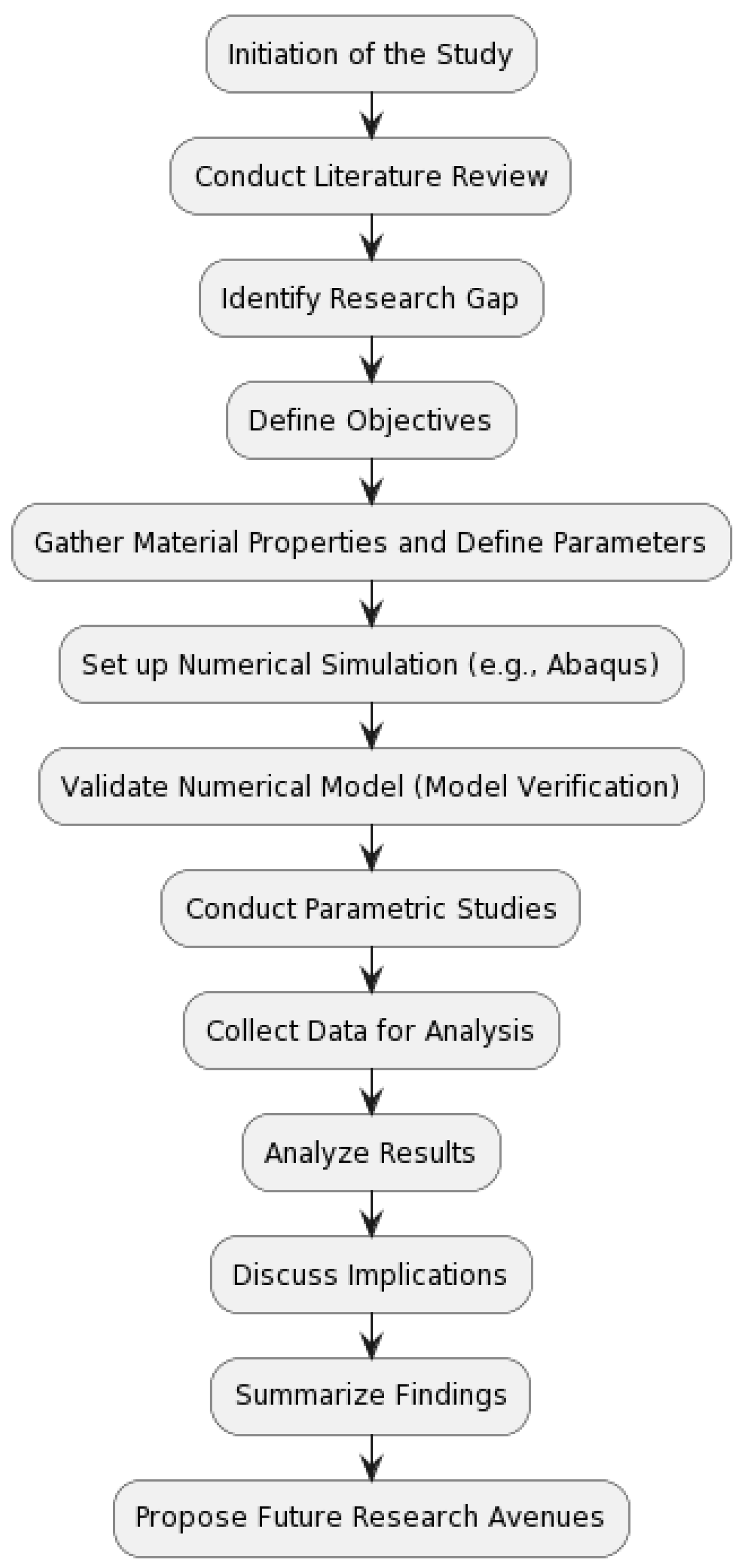
In this section, the study presents a detailed overview of the methodology employed to achieve the objectives outlined in the introduction. The study follows a systematic approach that encompasses a literature review, identification of research gaps, formulation of objectives, and comprehensive numerical analysis. The methodology is illustrated in the following flow chart (
Figure 1), providing a visual guide to the sequential steps undertaken in this research. Each step is carefully designed to ensure the accuracy and reliability of the numerical simulations conducted using software such as ABAQUS Version 6.10 [
31]. The section concludes with a brief summary highlighting the key aspects of the chosen methodology, setting the stage for the subsequent presentation of results in the following sections.
This structured methodology aims to contribute not only to the specific objectives of this study but also to the broader understanding of the axial load behavior of CFRP-strengthened CFST columns under diverse parametric scenarios. The clarity and transparency in the research approach enhance the reproducibility of the study and facilitate a comprehensive evaluation of the findings.
3. Experimental Study
The methodology of this research unfolds in three distinct stages. The first stage involves comparing the results of finite element (FE) analysis using ABAQUS software [
31] with the outcomes of an existing experimental test conducted by Han and Yao (2004) [
32]. The second stage entails generating a parametric study to investigate the impact of CFRP layers, length, and positions on the axial load behaviors of concrete-filled steel tube (CFST) composite columns strengthened with CFRP. This is achieved by designing various FE models with different configurations. In the third stage, the focus shifts to generating the FE analysis results, drawing conclusions, and presenting suggestions.
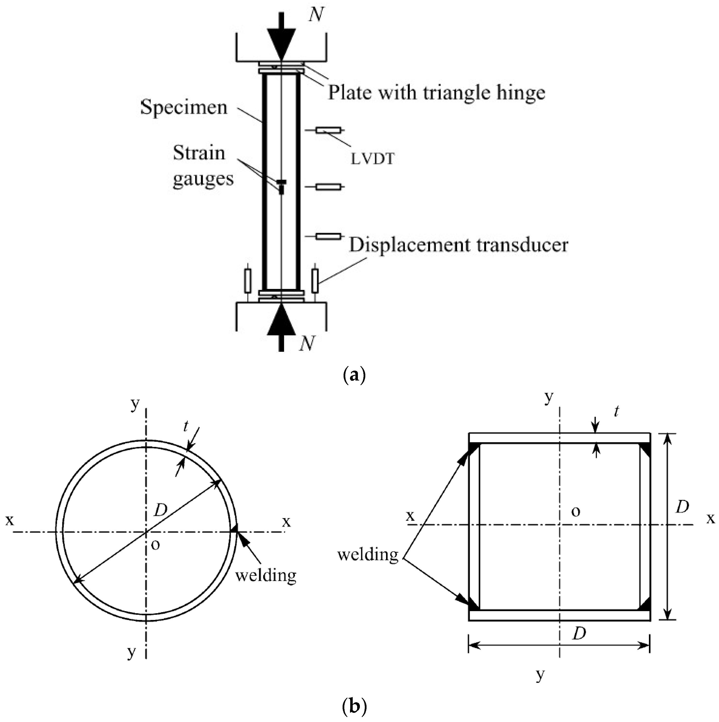
For verification purposes, an existing experimental study conducted by Han and Yao in 2004 was selected. This study comprised 38 specimens, including 18 stub columns and 20 beam columns. The key parameters varied in the tests and include (1) column section type, circular, and square; (2) tube diameter (or width) to thickness ratio, ranging from 33 to 67; and (3) load eccentricity ratio (e/r), varying from 0 to 0.3 mm.
Among the experimental models (38 in total), this research recommends choosing specimen one (labeled as LCSCI-1) in the existing study, which is considered a slender column. Specimen one is selected solely for the purpose of verifying the FE analysis; other specimens with different details that are not aligned with the main objective of this research are advised to be excluded. Essential details of the experimental specimen are presented in
Table 1, and the cross-section is depicted in
Figure 2.
4. Finite Element Modelling
Nonlinear full-scale finite element (FE) models were meticulously prepared, designed, and analyzed using ABAQUS software [
4]. The primary objective was to delve into the structural behavior of concrete-filled steel tube (CFST) composite columns strengthened with carbon fiber-reinforced polymers (CFRP) sheets. This section provides a comprehensive overview of the boundary conditions, element types, parts, meshing, and material modeling employed in the FE models.
The details of the FE models, including their setup and analysis, are thoroughly presented in this study.
4.1. Geometry, Element Assignment, Boundry Condition and Interaction
The initial finite element (FE) model was constructed using ABAQUS software [
31], aligning with the specifications of the experimental test and encompassing the loading system, test arrangement, and boundary conditions. This model aimed to replicate concrete-filled steel tube (CFST) composite columns reinforced with carbon fiber-reinforced polymer (CFRP) sheets. Notably, a comprehensive scale model (depicted in
Figure 3) was employed for all CFST composite columns in the FE simulation.
In this investigation, a progressive monotonic analysis was carried out using the displacement load approach. Loading was incrementally applied to specific points, increasing at a controlled rate of 0.1 mm/s. This process continued until the ultimate capacity of the CFRP-strengthened CFST composite columns was reached; the loading system in ABAQUS supported this procedure.
Within the ABAQUS software, the standard element library provides a range of element types. For this study, the S4R element type was chosen for the steel tube and CFRP components, while the C3D8R element type represented the concrete material. For a detailed breakdown of element selections for each segment of the FE model, refer to
Table 2.
To ensure alignment between the outcomes of the experimental test and the FE model, careful consideration of surface interactions among the constituent parts of the composite columns, including concrete, steel tube, CFRP, and adhesive substances, is essential. This aspect of parameter selection is pivotal and intricate.
Therefore, this study adopts the “cohesive behavior” technique for breakable nodes along the surface interaction between the steel tube and the CFRP. The full tie interaction technique was selected to represent the surface interaction between the inner surface of the steel tube and the outer surface of concrete. This choice is justified by assuming no slip along the surface interaction due to bending as the tube completely confines the concrete core at all loading stages. For more details,
Table 3 provides a summary of the interaction types between the parts of the composite column FE model.
4.2. Properties of Materials
This section provides an overview of the material properties incorporated into the study, offering a comprehensive understanding of their integration within the finite element (FE) models.
The material properties of steel in the FE models precisely mirrored those from the experimental parameters. These properties include Poisson’s ratio, modulus of elasticity, yield strength, ultimate strength, and ultimate strain, with values directly sourced from the pre-existing experimental study [
32]. Specifically, these values were 0.3, 206,500 MPa, 303.5 MPa, 400 MPa, and 0.05, respectively, as detailed in
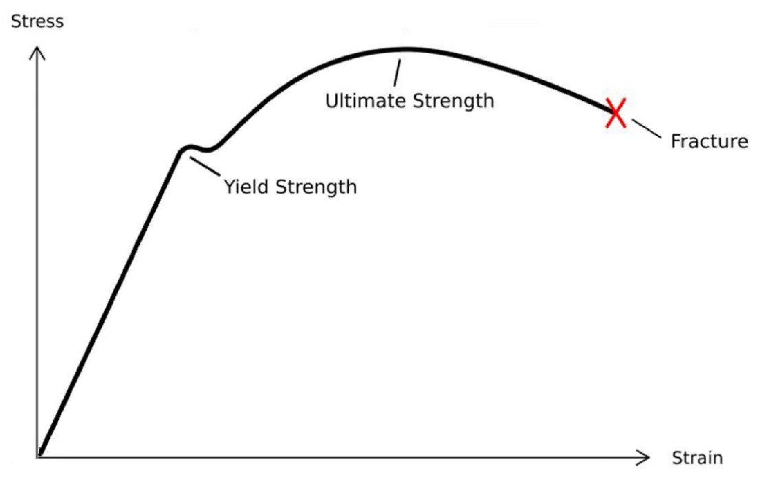
Table 4. The steel material is characterized as an elastic–plastic isotropic substance. Implementing these mechanical attributes in the FE models using ABAQUS involved opting for the elastic isotropic approach to define mechanical properties. The tri-linear stress–strain model, as presented by Han and Yao (2004) [
32] in
Figure 4, was embraced in this study to estimate stress–strain correlations within the FE models.
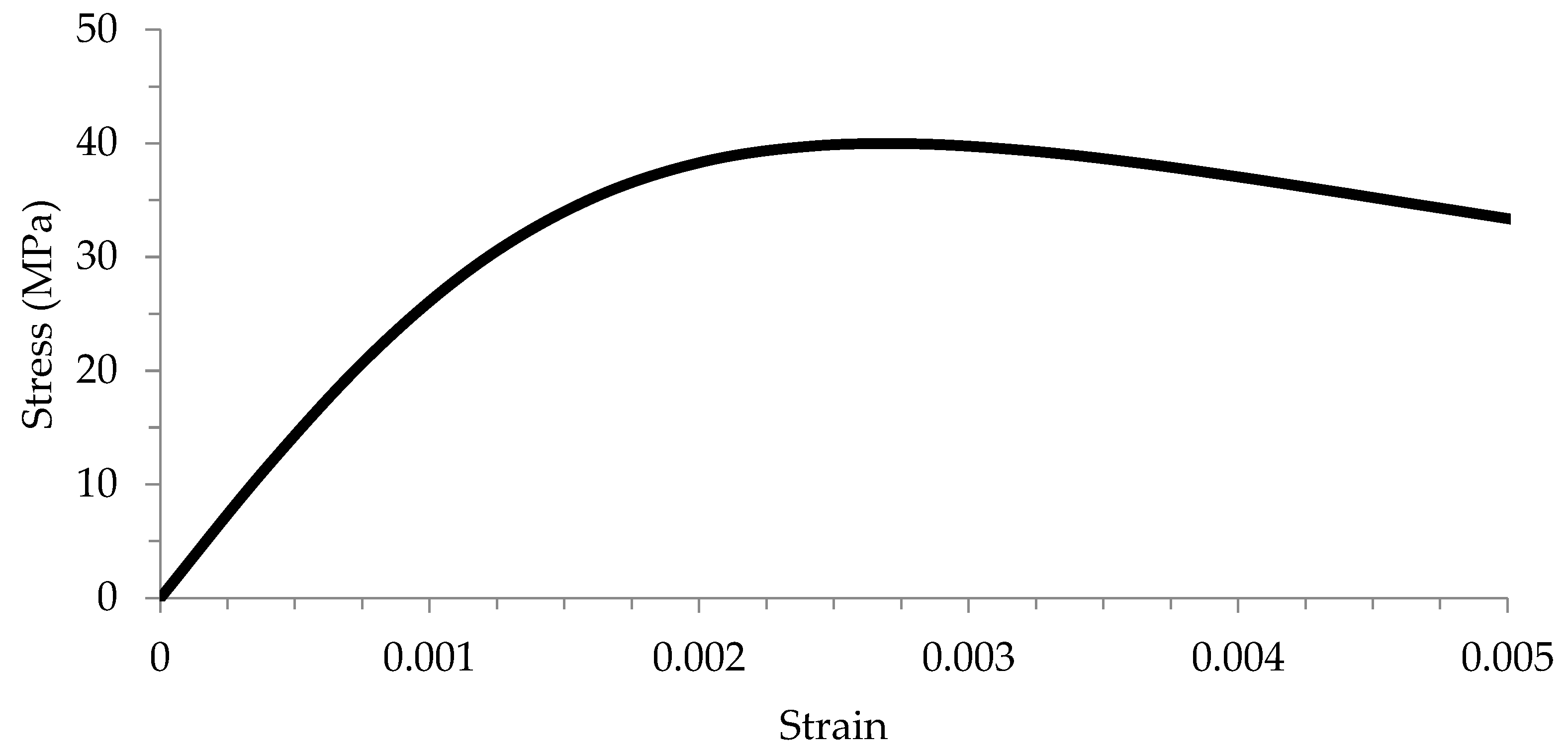
The concrete properties adopted in this study were directly extracted from the experimental tests. Compressive strength was assigned a value of 40 MPa, Poisson’s ratio 0.2, and the modulus of elasticity 37,420 MPa, as outlined in
Table 5. Concrete, in its essence, is an isotropic substance. To represent its mechanical elasticity in the FE models through ABAQUS, the elastic isotropic approach was employed to define the modulus of elasticity and Poisson’s ratio. Additionally, the mechanical plasticity properties were identified through the selection of the concrete damaged plasticity option.
Figure 5 depicts the stress–strain relationship for concrete, adopting the same equations as Sundarraja and Prabhu (2011) [
33].
For enhancing CFST columns, unidirectional CFRP sheets of the MBrace 240 type were introduced. The CFRP sheet is characterized by a modulus of elasticity of 240,000 MPa, ultimate tensile strength of 1747 MPa, sheet thickness of 1.2 mm, and Poisson’s ratio of 0.4, as provided in
Table 6. CFRP material follows an elastic-brittle nature, and its mechanical properties are represented through the fiber reinforced polymer-Hashin Damage model [
1,
6,
34,
35,
36]. This material is treated as orthotropic, and its elastic-engineering constants are harnessed to determine key elasticity properties, including the modulus of elasticity, Poisson’s ratio, and shear modulus.
5. Convergence Study
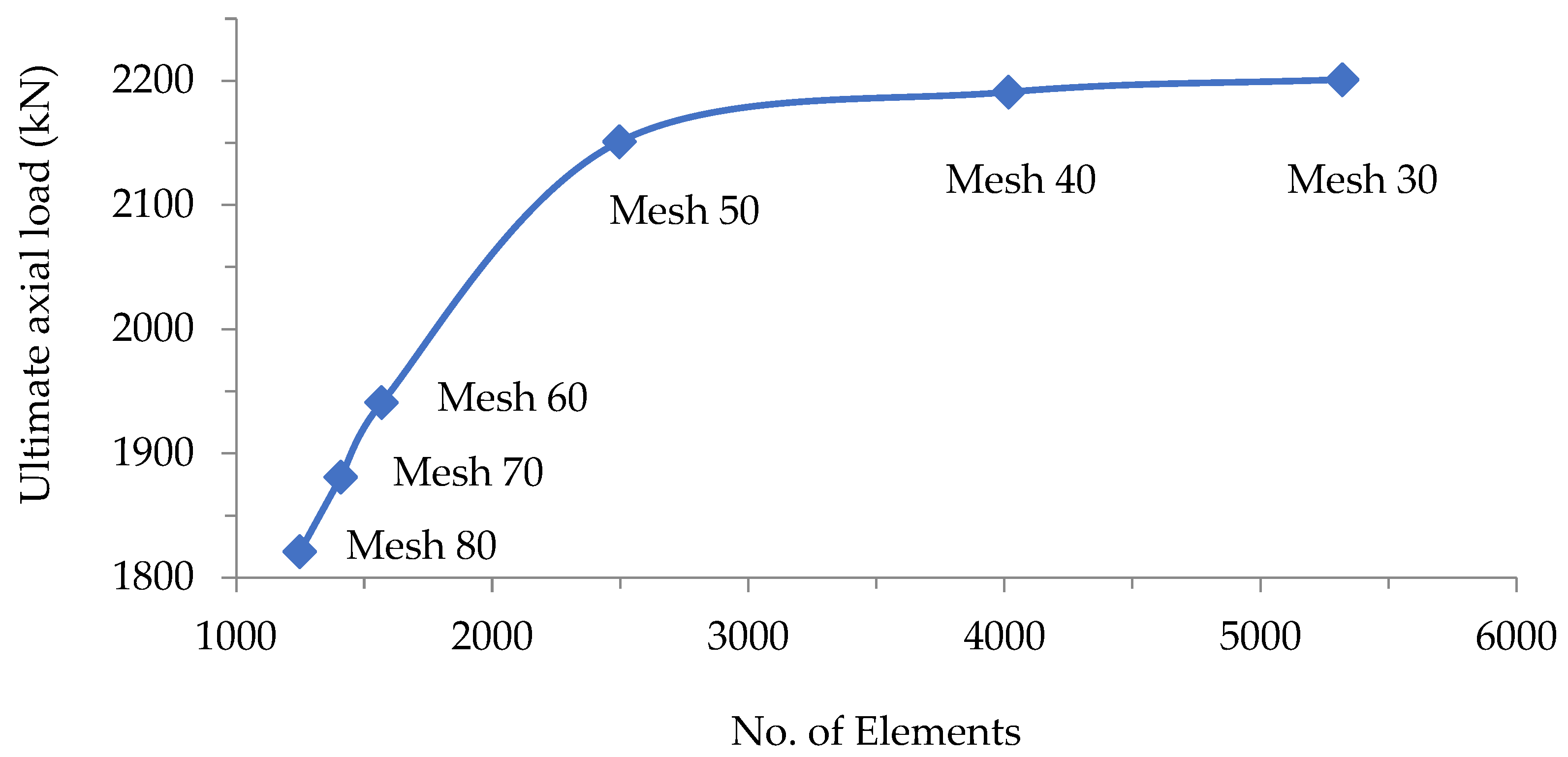
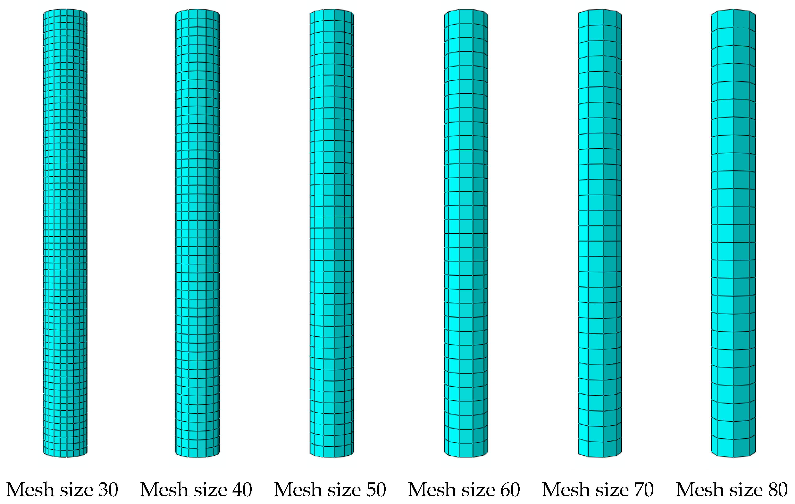
In this study, a convergence study was conducted to determine the suitable meshing for the finite element (FE) modeling in non-linear analysis of concrete-filled steel tube (CFST) composite columns. To identify the optimal meshing size, six different mesh sizes—30, 40, 50, 60, 70, and 80 mm—were applied and analyzed, as depicted in
Figure 6. These meshing sizes were associated with different ultimate axial loading conditions.
The study revealed that there was no considerable difference in axial loading resistance between the models with 60 mm meshing size and 70 mm meshing size, as illustrated in
Figure 7. The ultimate axial load for the FE model with a 60 mm meshing size was 1941 kN, while that for the FE model with a 70 mm meshing size was 1841 kN—very close to the experimental ultimate axial loading of 1818 kN, as presented in
Figure 7.
This study recommends choosing a meshing size of 70 mm for all the remaining composite column FE models due to its high accuracy and reduced analysis time compared with other mesh sizes.
This convergence study ensures the reliability and accuracy of the FE models by selecting an appropriate meshing size, thereby facilitating a more efficient and precise analysis of the CFST composite columns.
6. Verification Study
In the current study, verification was conducted using an existing experimental study by Han and Yao (2004) [
32]. Specimen one, labeled as LCSCI-1 in the existing study, was selected for verification, and its details and properties are presented in
Table 7.
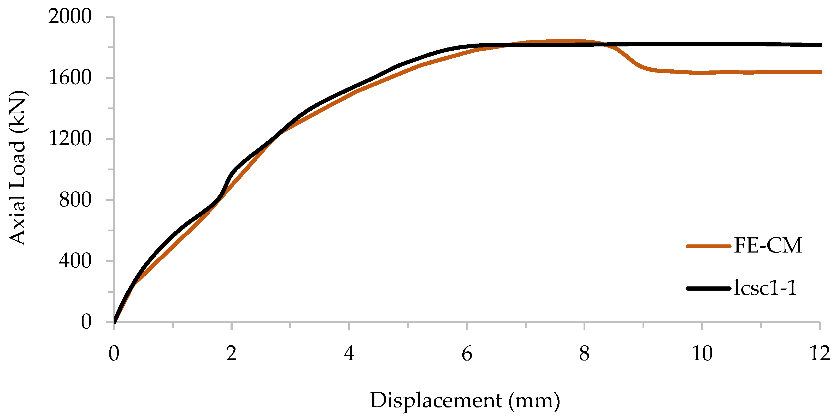
A FE model, labeled as Cir-CM, was designed and analyzed with parameters exactly the same as the experimental test, and the results were compared. The ultimate axial loading for the experimental test was 1818 kN with a displacement of 5.5 mm, and it was 1841 kN for the FE model with a displacement of 5.8 mm, as presented in
Table 8.
Accuracy of the FE verification was achieved through this comparison, and the deviation percentage was only 1.2%, as presented in
Figure 8. This deviation is considered to be very close to the experimental results. The verified FE model (FE-CM) was selected as a control model for all the parametric studies.
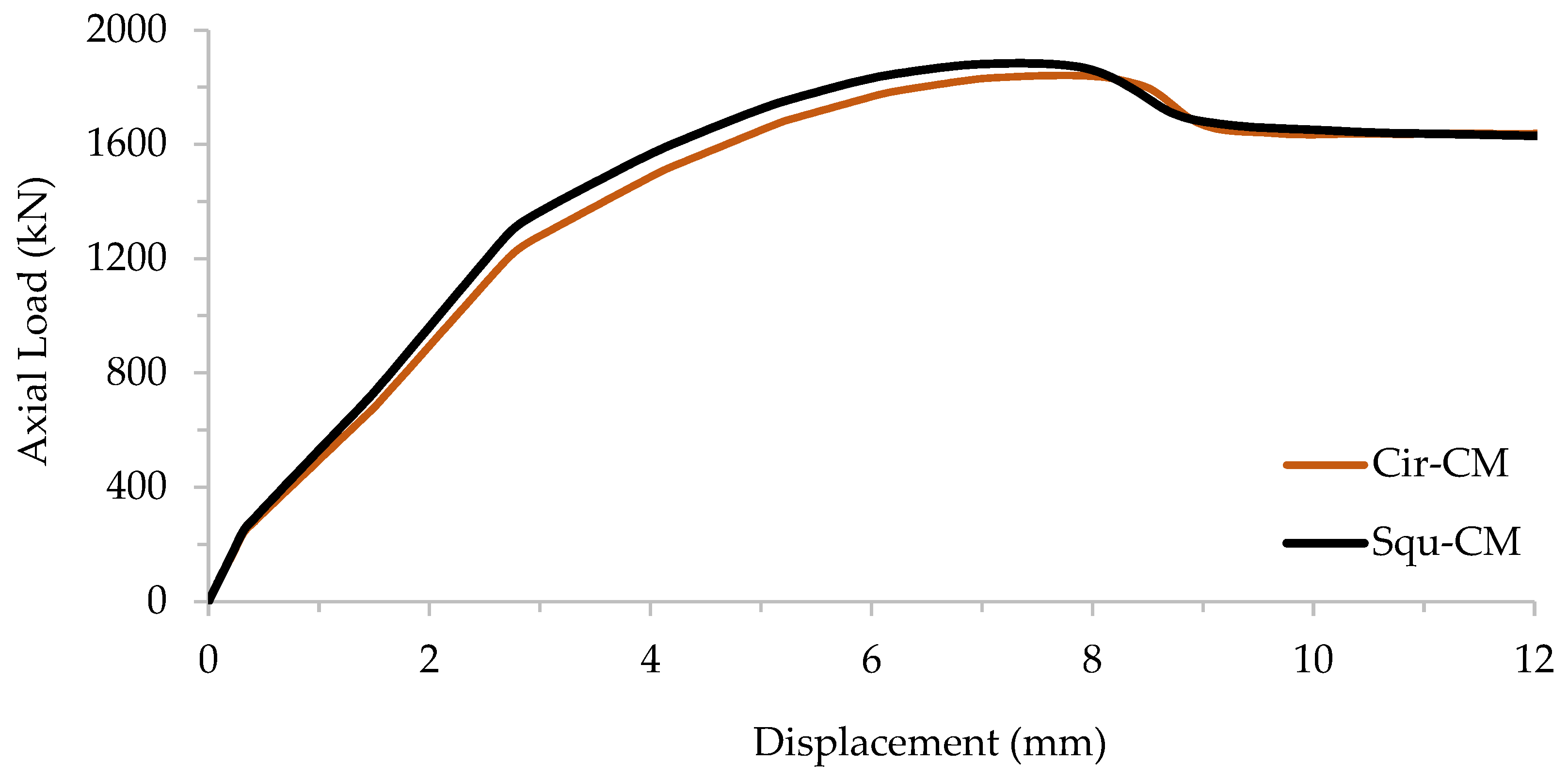
In this study, the effect of CFRP sheets on the square concrete-filled steel tube (CFST) composite column was also investigated. A FE model was designed and analyzed, and its properties were exactly the same as the experimental test. The cross-sectional area for the square CFST was 30,625 mm
2, similar to the circular CFST cross-sectional area of 31,415.9 mm
2. Moreover, the moment of inertia for both cross-sections was very close, being around 78,157,552 mm
4.
Figure 9 presents the axial load—displacement for the circular and square CFST control models to demonstrate that these two different cross-sections exhibited very similar load–displacement behavior.
7. Parametric Study
This study aims to investigate the impact of various parameters on the axial load behavior of circular and square concrete-filled steel tube (CFST) composite columns strengthened with carbon fiber-reinforced polymers (CFRP). The key parameters include the number of CFRP layers, their positions, and confinement lengths for both circular and square cross-sections.
7.1. Effect of CFRP Layer Numbers
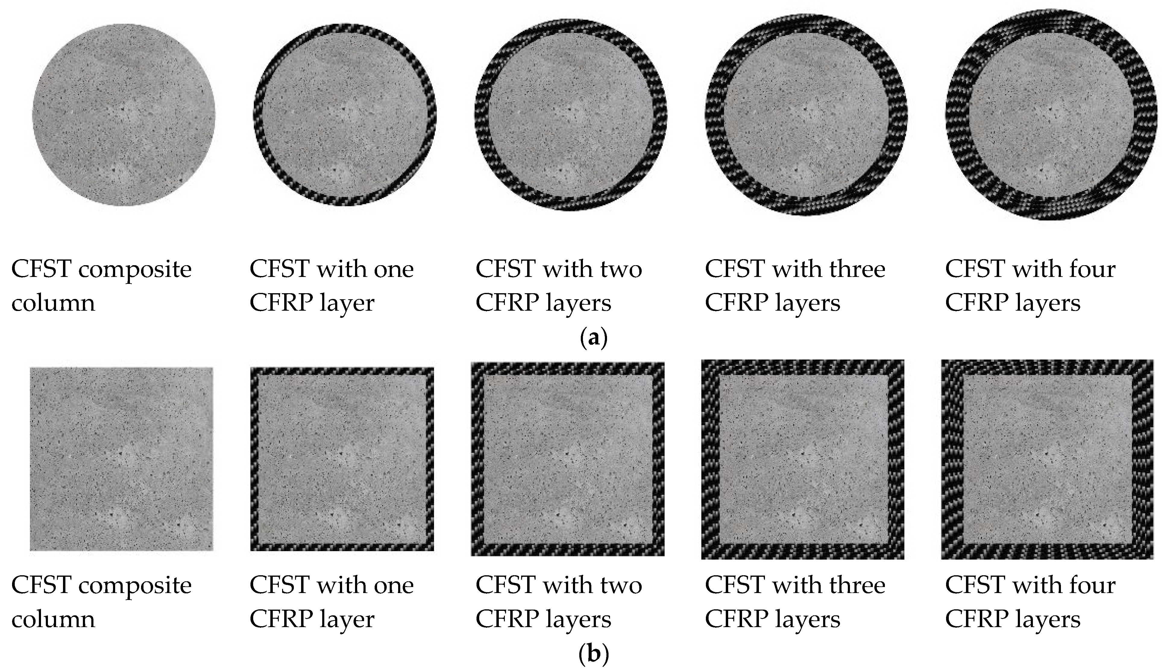
The effect of CFRP layers on the axial load behavior of circular and square CFST composite columns was examined. Eight finite element (FE) models were designed and analyzed, divided into two groups based on cross-sectional shape. The first group consisted of circular models (Cir-1.2, Cir-2.4, Cir-3.6, Cir-4.8), and the second group featured square models (Squ-1.2, Squ-2.4, Squ-3.6, Squ-4.8).
Figure 10 illustrates the cross-sectional shapes of these models.
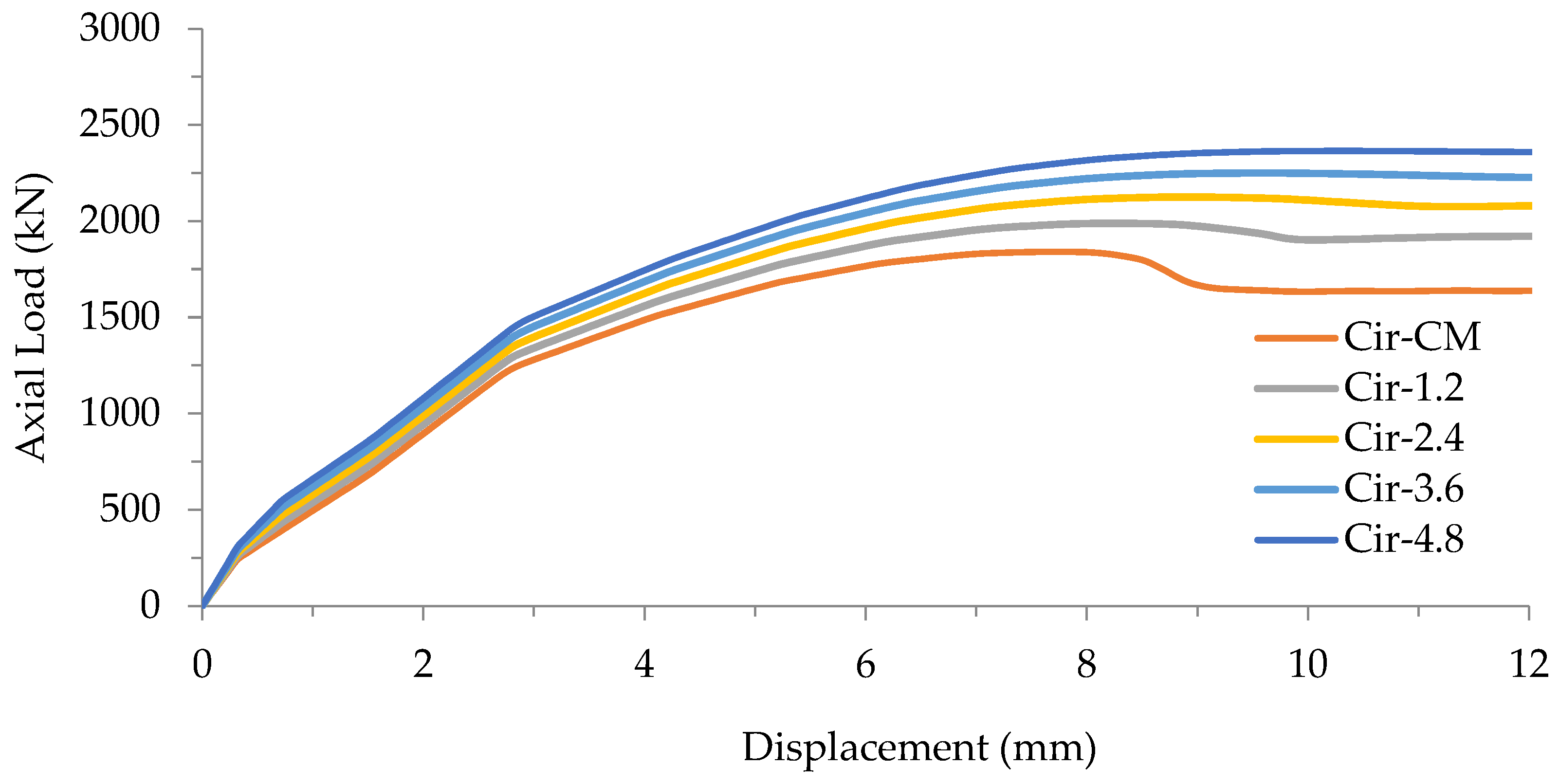
By evaluating the impact of varying CFRP sheet quantities on the axial load behavior of circular concrete-filled steel tube (CFST) composite columns, we compared the ultimate axial load of the initial FE model group with circular cross-sectional shapes to that of the control model (Cir-CM). The ultimate axial load values for FE models Cir-1.2, Cir-2.4, Cir-3.6, and Cir-4.8 were 1998 kN, 2275 kN, 2488 kN, and 2660 kN, respectively. These results are presented in
Table 9 alongside a corresponding displacement of approximately 5.6 mm.
The results affirm a positive correlation between the number of CFRP layers and the axial load behavior of circular CFST composite columns. The introduction of one CFRP layer (1.2 mm thickness) enhanced the structural strength by 8.5%, two layers (2.4 mm thickness) by 23.5%, three layers (3.6 mm thickness) by 35.1%, and four layers (4.8 mm thickness) by 44.5%, as illustrated in
Figure 11.
The outcomes reveal a positive correlation between the quantity of CFRP layers and the axial load behavior of circular CFST composite columns. As CFRP layers were incrementally added, the axial load capacity showed a notable improvement. Beyond the enhanced axial load capacity, it is insightful to delve into the impact of CFRP quantity on the structural response, particularly focusing on the stiffness of the specimens.
The stiffness of a structure is a critical parameter that defines its ability to resist deformation under an applied load. From the perspective of structural response, the increase in axial load capacity with additional CFRP layers suggests an enhancement in the overall stiffness of the specimens. This improvement is attributed to the reinforcing effect of CFRP layers, which effectively restrain deformations and increase the column’s rigidity. By observing the displacement values in
Table 9, it is evident that as the number of CFRP layers increases the corresponding displacements decrease. This reduction in displacements signifies a stiffer response of the composite columns, indicating that the incorporation of CFRP layers contributes to enhanced structural stiffness. In conclusion, the analysis underscores that the positive influence of CFRP sheets on axial load capacity is coupled with a concurrent improvement in the structural stiffness of circular CFST composite columns. This dual enhancement reinforces the effectiveness of CFRP strengthening not only in bearing higher loads but also in providing a more robust and resilient structural response.
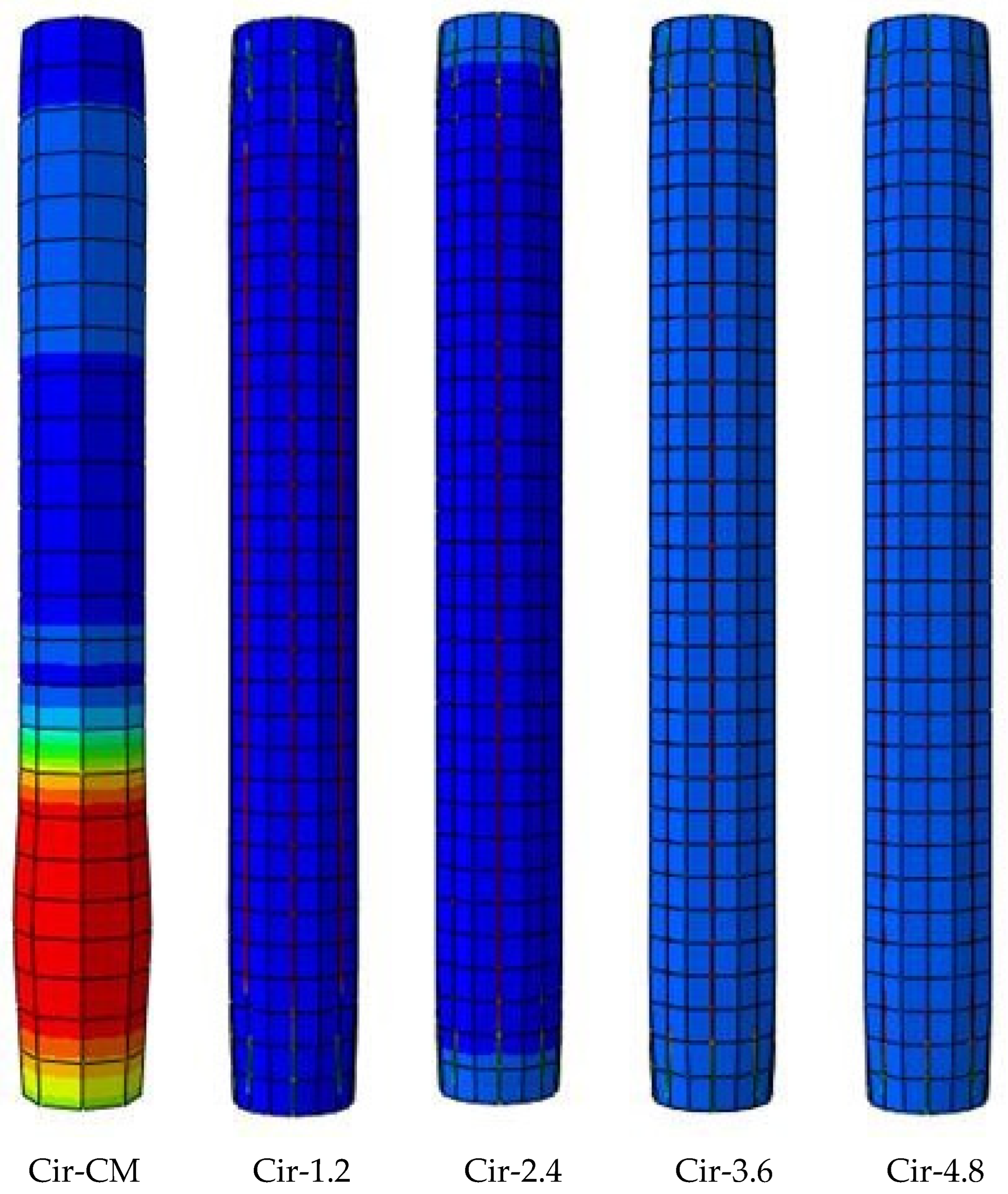
Analyzing the stress distribution in
Figure 12 unveils that CFRP layers contribute to a more uniform stress distribution, thus mitigating local buckling and bolstering concrete compression resistance. Notably, this parametric study suggests that beyond the enhanced axial load capacity, the CFRP layers positively influence the overall stiffness of the specimens, a fact that manifests itself in a more controlled and distributed structural response.
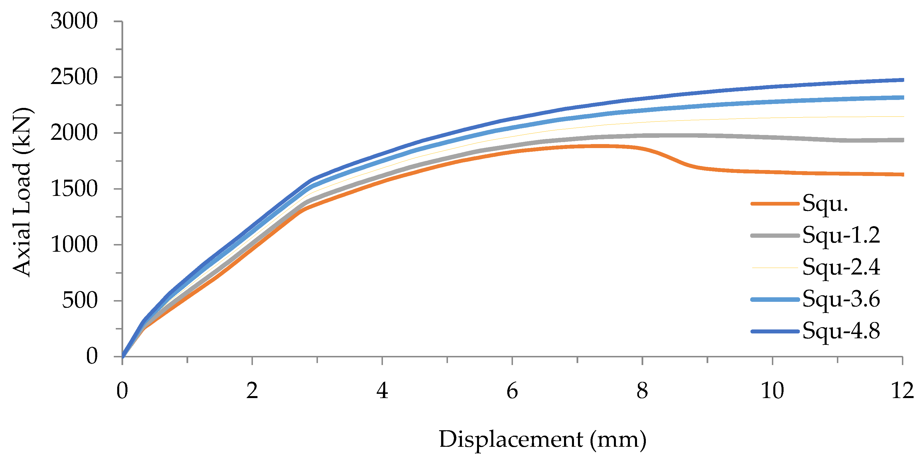
In examining the influence of varying quantities of CFRP sheets on the axial load behavior of square CFST composite columns, we compared the ultimate axial load of FE models using square cross-sectional shapes with that of the control model (Squ). The ultimate axial load values for FE models Squ-1.2, Squ-2.4, Squ-3.6, and Squ-4.8 were 1979 kN, 2112 kN, 2235 kN, and 2713 kN, respectively. These results are presented in
Table 10, with a consistent displacement of around 5.7 mm observed across all FE models.
For square CFST composite columns, the results demonstrated a positive influence of CFRP layers. The incorporation of one CFRP layer increased the strength by 5.1%, two layers by 12.1%, three layers by 18.6%, and four layers by 44.0%, as depicted in
Figure 13.
The outcomes reveal a positive correlation between the quantity of CFRP layers and the axial load behavior of square CFST composite columns. The axial load capacity demonstrated a consistent improvement with the incremental addition of CFRP layers. Beyond the enhanced axial load capacity, an analysis of the structural response, particularly focusing on the stiffness of the specimens, provides valuable insights.
The stiffness of a structure is a crucial factor determining its resistance to deformation under an applied load. In this context, the increase in axial load capacity with additional CFRP layers suggests an enhancement in the overall stiffness of the specimens. This improvement is indicative of the reinforcing effect of CFRP layers, effectively limiting deformations and increasing the rigidity of the square CFST composite columns. Observing the displacement values in
Table 10, it becomes apparent that as the number of CFRP layers increases, the corresponding displacements decrease. This reduction in displacements signifies a stiffer response of the composite columns, implying that the incorporation of CFRP layers contributes to improved structural stiffness. In summary, the analysis underscores that the positive impact of CFRP sheets on axial load capacity in square CFST composite columns aligns with a concurrent improvement in structural stiffness. This dual enhancement not only enables the columns to withstand higher loads but also ensures a more resilient and robust structural response.
7.2. Effect of CFRP Confinement Length
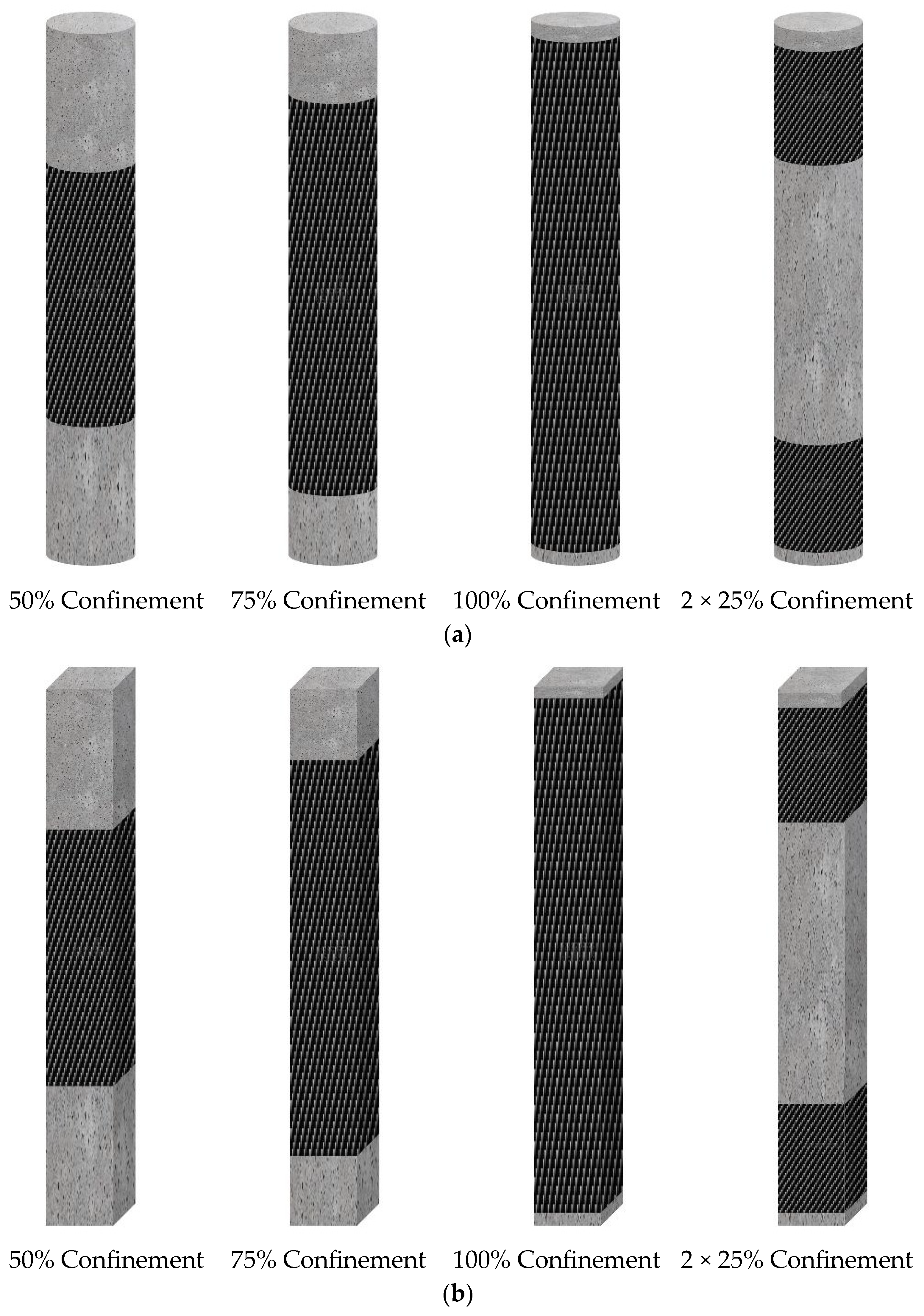
The study explored the confinement impact of CFRP sheets on the axial load behavior of CFST composite columns. Eight additional FE models underwent design and analysis, being organized into two groups. The first group comprised four models with a circular cross-sectional shape. The initial model featured 50% CFRP sheets that confined the total length of the CFST composite columns positioned at the mid-span. The second model had 75% CFRP sheets confinement also at the mid-span. The third model featured 100% CFRP sheets confinement throughout its total length. The fourth model incorporated two 25% CFRP sheets confined to the CFST composite columns’ total lengths, with the first 25% on the top side and the second 25% on the bottom side, as illustrated in
Figure 14a. The second group included four distinct FE models designed with a square cross-sectional shape. The CFRP sheets’ confinement for these square CFST composite columns mirrored the design of the first group and is depicted in
Figure 14b.
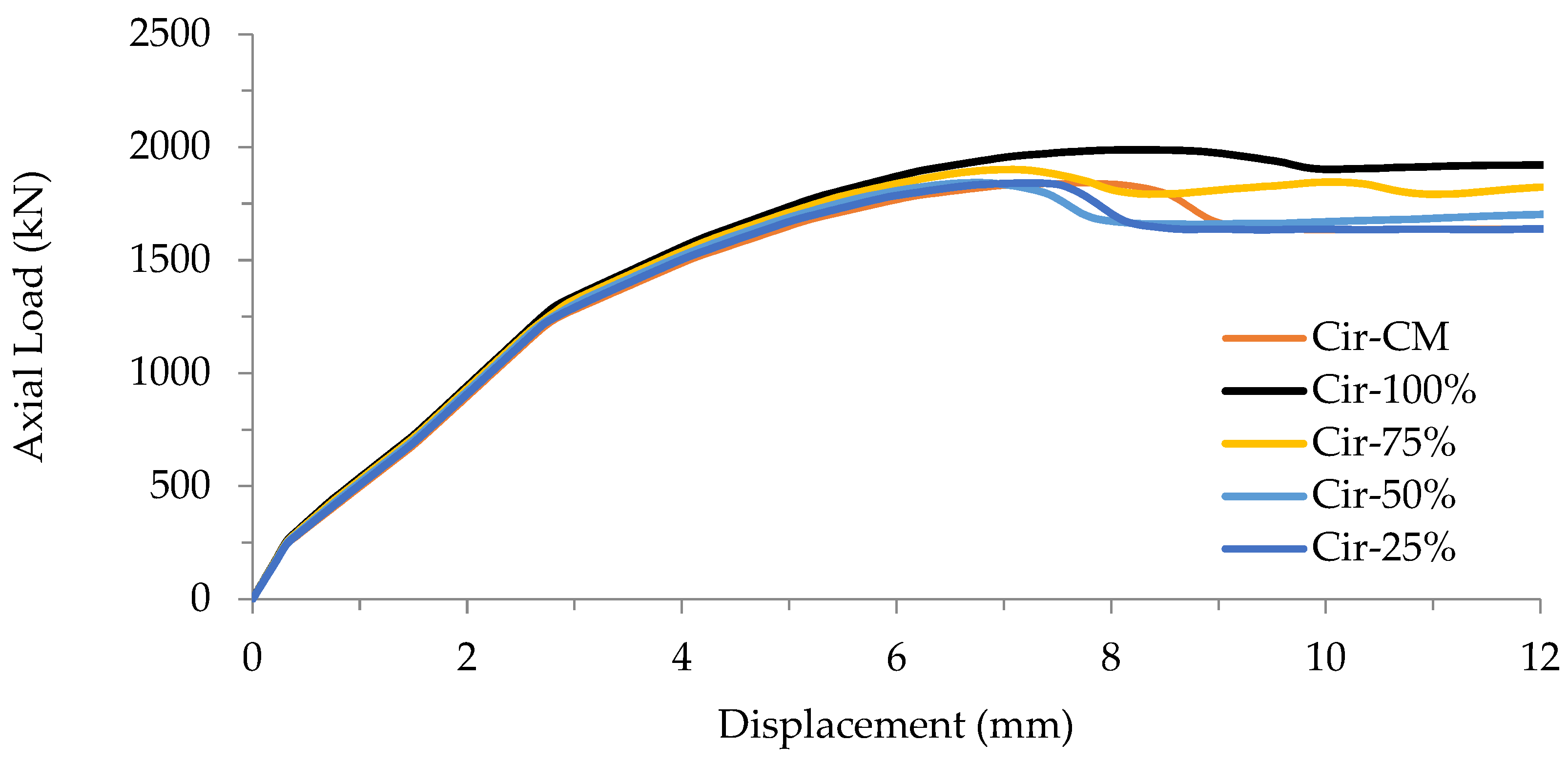
The results demonstrate that the ultimate axial loads for the FE models in the first group (circular cross-section) were as follows: 1998 kN for Cir100%, 1927 kN for Cir-75%, 1843 kN for Cir-50%, and 1842 kN for Cir-2 × 25%. These values corresponded to a displacement of 5.7 mm for all the FE models, as detailed in
Table 11. Improvement percentages were calculated to gauge the impact of CFRP strengthening with varying lengths. The improvements were 8.5%, 4.6%, 0.10%, and 0.05% for FE models Cir-100%, Cir-75%, Cir-50%, and Cir-2 × 25%, respectively, as illustrated in
Figure 15.
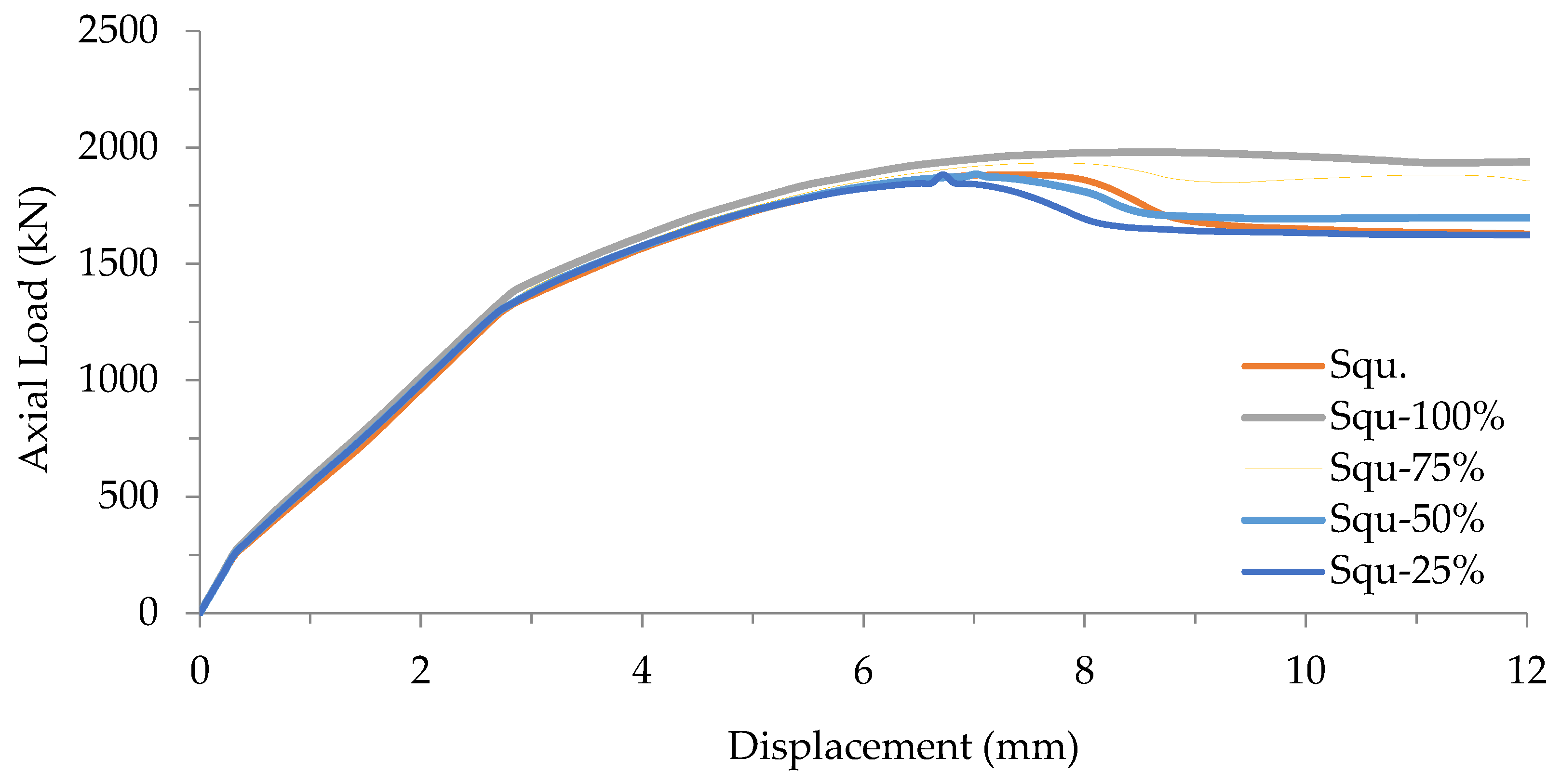
The outcomes indicate that the ultimate axial loads for the second group (square cross-sectional shape) of the FE models were as follows: 1979 kN for Squ-100%, 1934 kN for Squ-75%, 1885 kN for Squ-50%, and 1884 kN for Squ-2 × 25%. These results were associated with a displacement of approximately 5.7 mm for all these FE models, as outlined in
Table 12. Improvement percentages were documented to assess the influence of CFRP strengthening with different lengths. The enhancements were 5.10%, 2.71%, 0.11%, and 0.05% for FE models Squ-100%, Squ-75%, Squ-50%, and Squ-2 × 25%, respectively, as depicted in
Figure 16.
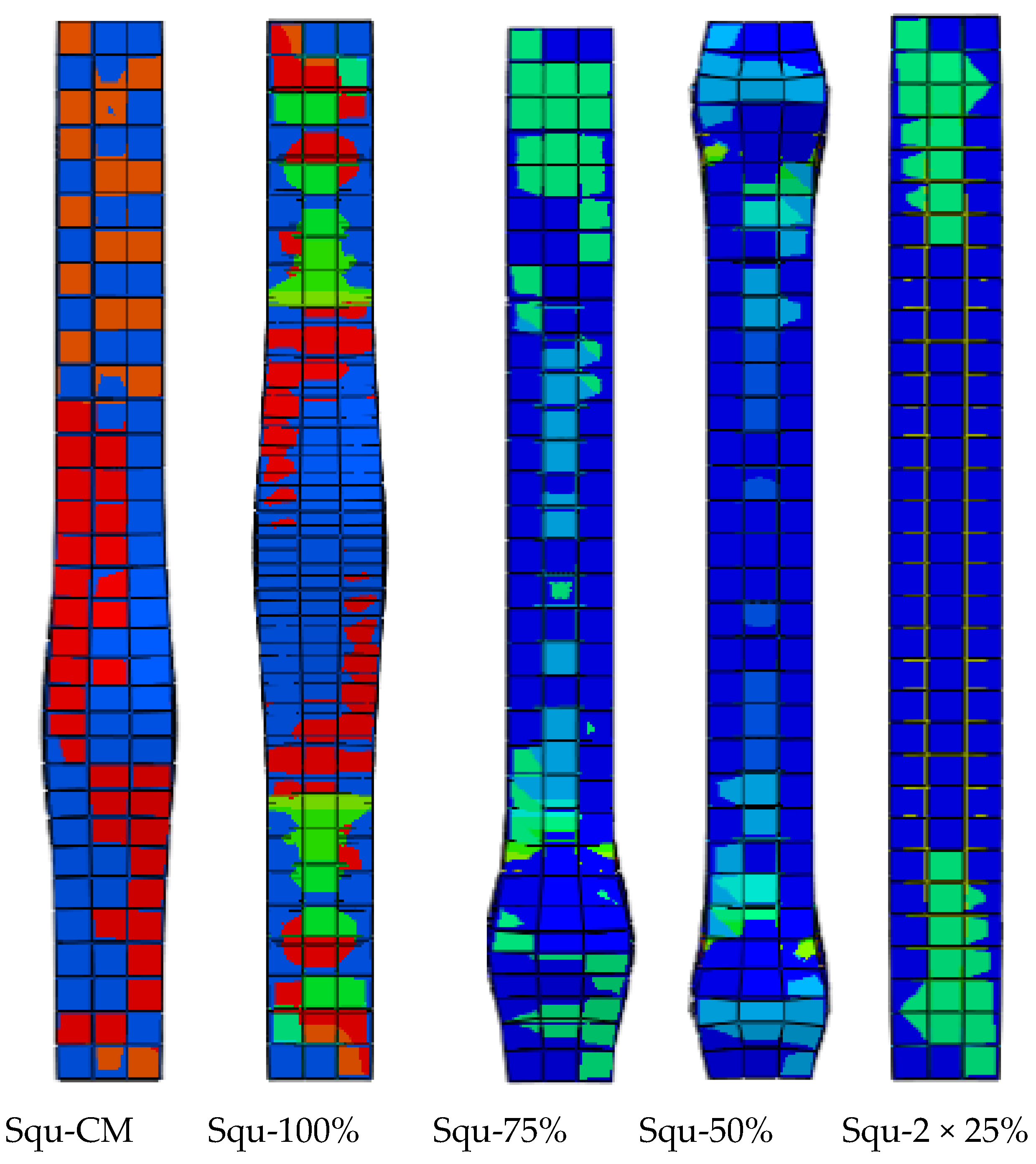
The stress distribution of the FE square CFST composite columns, reinforced with CFRP sheets of varying lengths, is illustrated in
Figure 17. In FE models Squ-100%, Squ-75%, Squ-50%, and Squ-2 × 25%, the failure mode was localized in the region that remained unconfined by CFRP. In contrast, control model Squ-CM (without CFRP) exhibited local buckling at the mid-span. The FE results conclusively demonstrated that the incorporation of CFRP sheets mitigates local buckling and enhances overall resistance to axial loading.
Parallel to the investigation into axial load behavior, an in-depth analysis of the structural stiffness was conducted for the square CFST composite columns. The stiffness of each model, including Squ-CM, Squ-100%, Squ-75%, Squ-50%, and Squ-2 × 25%, was rigorously examined to understand the impact of CFRP strengthening on their structural response. The results unveiled a discernible enhancement in stiffness attributed to the incorporation of CFRP sheets. Noteworthy improvements were observed with an increasing number of CFRP layers and varying confinement lengths, showcasing the effectiveness of the CFRP reinforcement method in enhancing the structural stiffness of square cross-sectional composite columns. This stiffness analysis provides critical insights into the deformation characteristics and load-bearing capacity of the square CFST composite columns, offering essential information for evaluating the overall efficacy and performance of the CFRP strengthening approach in this specific geometrical configuration.
8. Failure Mode and Discussion
In this section, we thoroughly examine the predicted failure modes from our finite element (FE) analysis and compare them with the outcomes of a pertinent experimental study conducted by Han and Yao in 2004.
The core objective of this study was to meticulously assess the accuracy of our FE analysis in predicting the failure modes of carbon fiber-reinforced polymer (CFRP)-strengthened concrete-filled steel tube (CFST) composite columns. The verification process involved a strategic selection of a specific specimen, LCSCI-1, from the existing experimental dataset, aligning closely with the objectives of our research.
To determine the onset of failure, we adopted a comprehensive methodology that included the following points:
Comparison parameters: Key parameters, such as ultimate axial load behavior and failure mode predictions, were rigorously compared between our FE analysis and the experimental dataset.
Specimen selection: LCSCI-1 was chosen based on its relevance to our research objectives by considering factors like column section type, tube diameter to thickness ratio, and load eccentricity ratio.
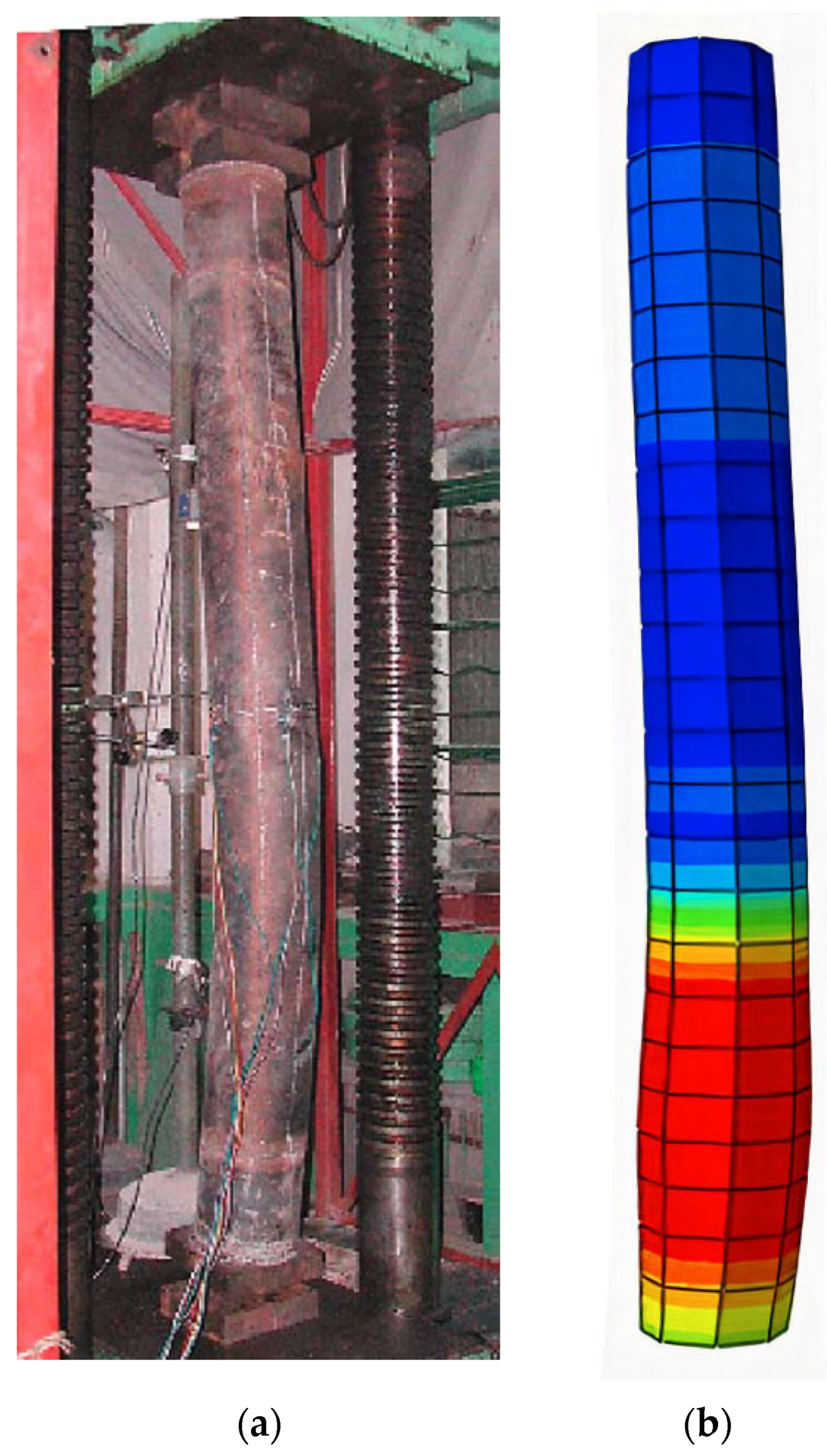
Visual representation:
Figure 18 visually illustrates the exceptional agreement between FE analysis and experimental findings. This figure serves as a graphical confirmation of the alignment in failure mode predictions for LCSCI-1.
Quantitative assessment: The study emphasized not only qualitative but also quantitative agreement between FE predictions and experimental outcomes. This approach ensures a robust assessment of the failure mode by considering factors such as von Mises stress, plastic equivalent stress, and structural displacements.
The results of the FE analysis demonstrated an impressive alignment with the experimental findings, particularly in terms of ultimate axial load behavior and failure mode prediction.
Figure 18 serves as a testament to the accuracy of our FE model in capturing the specific failure mode exhibited by specimen LCSCI-1.
This study contributes a comprehensive assessment of the axial load behavior of CFST composite columns strengthened with CFRP sheets. The robustness and reliability of our FE analysis in accurately predicting failure modes, as confirmed through experimental validation, underscore its significance for enhancing our understanding of the structural behavior of CFRP-strengthened CFST columns.
9. Conclusions
In conclusion, this study offers a comprehensive investigation into the axial load behavior of circular and square CFST composite columns, which is enhanced by varying quantities of CFRP sheets and distinct confinement percentages. Through a meticulous comparison with a previous experimental test by Han and Yao (2004) and through leveraging Abaqus software for the analysis of 18 distinct FE models, the study delves into the impact of CFRP sheet counts and confinement lengths across different cross-sectional shapes.
The key findings unveil substantial enhancements in column strength through the application of CFRP sheets. Notably, the incorporation of a single CFRP sheet (1.2 mm thickness) resulted in a significant increase of 8.5% in circular cross-sections and 5.1% in square cross-sections. Furthermore, the use of two CFRP sheets (2.4 mm thickness) led to a substantial 23.5% increase in circular cross-sections and a no
Table 12.1% enhancement of square cross-sections. Increasing the number of CFRP sheets to three (3.6 mm thickness) achieved a remarkable 35.1% reinforcement for circular cross-sections and an 18.6% enhancement for square cross-sections. Similarly, the application of four CFRP sheets (4.8 mm thickness) yielded an impressive 44.5% increase in column strength for circular cross-sections and a substantial 44.0% enhancement for square cross-sections. Furthermore, the study observed that strengthening composite columns with varying lengths of CFRP sheets (100%, 75%, 50%, and 2 × 25%) led to improvements of 8.5%, 4.6%, 0.1%, and 0.5%, respectively, in circular cross-sections and 5.10%, 2.71%, 0.11%, and 0.05%, respectively, in square cross-sections.
These findings underscore the significant contribution of CFRP sheets to enhancing the axial load behavior of CFST composite columns, providing valuable insights for structural engineers and researchers. The study sets the stage for future research, suggesting avenues to explore alternative materials and methodologies, thereby ensuring continued advancements in composite column strengthening techniques for circular and square cross-sections.
Author Contributions
Conceptualization, S.M.S., S.J.H. and S.S.S.; methodology, S.M.S., S.J.H., M.J.H., S.S.S., M.M.F. and M.A.Y.; software, S.J.H., S.S.S., M.M.F. and M.A.Y.; validation, S.M.S., S.J.H., S.S.S., M.M.F. and M.A.Y.; formal analysis, M.M.F. and M.A.Y.; investigation, S.M.S., S.J.H., M.J.H. and S.S.S.; resources, S.M.S., S.J.H., M.J.H., M.M.F. and M.A.Y.; data curation, S.M.S., S.J.H., M.J.H., S.S.S. and M.M.F.; writing—original draft, S.M.S., S.J.H., M.J.H., S.S.S., M.M.F. and M.A.Y.; writing—review & editing, S.M.S., S.J.H., M.J.H., S.S.S. and M.M.F.; visualization, S.M.S., M.J.H. and M.M.F.; supervision, S.M.S., M.J.H. and M.M.F.; project administration, S.M.S., S.J.H., M.J.H., S.S.S. and M.M.F.; funding acquisition, S.M.S., S.J.H., M.J.H., S.S.S., M.M.F. and M.A.Y. All authors have read and agreed to the published version of the manuscript.
Funding
This research received no external funding.
Data Availability Statement
The data are presented in the article.
Conflicts of Interest
The authors declare no conflict of interest.
References
- Al Zand, A.W.; Badaruzzaman, W.H.W.; Mutalib, A.A.; Qahtan, A. Finite element analysis of square CFST beam strengthened by CFRP composite material. Thin-Walled Struct. 2015, 96, 348–358. [Google Scholar] [CrossRef]
- Contento, A.; Aloisio, A.; Xue, J.; Quaranta, G.; Briseghella, B.; Gardoni, P. Probabilistic axial capacity model for concrete-filled steel tubes accounting for load eccentricity and debonding. Eng. Struct. 2022, 268, 114730. [Google Scholar] [CrossRef]
- Liao, J.; Zeng, J.-J.; Long, Y.-L.; Cai, J.; Ouyang, Y. Behavior of square and rectangular concrete-filled steel tube (CFST) columns with horizontal reinforcing bars under eccentric compression. Eng. Struct. 2022, 271, 114899. [Google Scholar] [CrossRef]
- Hilo, S.J.; Sabih, S.M.; Faris, M.M.; Al-Zand, A.W. Numerical Investigation on the Axial Load Behaviour of Polygonal Steel Tube Columns. Int. Rev. Civ. Eng. 2022, 13, 397. [Google Scholar] [CrossRef]
- Hilo, S.J.; Sabih, S.M.; Abdulrazzaq, M.M. Numerical Analysis on the Behavior of Polygonal CFST Composite Columns under Axial Loading Using Finite Element. J. Eng. Sci. Technol. 2021, 16, 4975–4999. [Google Scholar]
- Abdulrazzaq, M.M.; Hilo, S.J.; Sabih, S.M.; Hilmi, S.A.; Al-Zand, A.W.; Ali, M.M. Numerical investigation for the flexural load behaviour of profiled composite slab strengthened with CFRP. Mater. Today Proc. 2022, 61, 1115–1125. [Google Scholar] [CrossRef]
- Al Zand, A.W.; Badaruzzaman, W.H.W.; Mutalib, A.A.; Hilo, S.J. The enhanced performance of CFST beams using different strengthening schemes involving unidirectional CFRP sheets: An experimental study. Eng. Struct. 2016, 128, 184–198. [Google Scholar] [CrossRef]
- Uy, B. Concrete-filled fabricated steel box columns for multistorey buildings: Behaviour and design. Prog. Struct. Eng. Mater. 1998, 1, 150–158. [Google Scholar] [CrossRef]
- Haj-Ali, R.; Kilic, H. Nonlinear behavior of pultruded FRP composites. Compos. Part B Eng. 2002, 33, 173–191. [Google Scholar] [CrossRef]
- Han, L.-H.; Tao, Z.; Huang, H.; Zhao, X.-L. Concrete-filled double skin (SHS outer and CHS inner) steel tubular beam-columns. Thin-Walled Struct. 2004, 42, 1329–1355. [Google Scholar] [CrossRef]
- Belarbi, A.; Acun, B. FRP systems in shear strengthening of reinforced concrete structures. Procedia Eng. 2013, 57, 2–8. [Google Scholar] [CrossRef]
- Begich, Y.; Klyuev, S.; Jos, V.; Cherkashin, A. Fine-grained concrete with various types of fibers. Mag. Civ. Eng. 2020, 5, 9702. [Google Scholar]
- Huang, H.; Yuan, Y.; Zhang, W.; Zhu, L. Property assessment of high-performance concrete containing three types of fibers. Int. J. Concr. Struct. Mater. 2021, 15, 39. [Google Scholar] [CrossRef]
- Hannawi, K.; Bian, H.; Prince-Agbodjan, W.; Raghavan, B. Effect of different types of fibers on the microstructure and the mechanical behavior of ultra-high performance fiber-reinforced concretes. Compos. Part B Eng. 2016, 86, 214–220. [Google Scholar] [CrossRef]
- Van Den Einde, L.; Zhao, L.; Seible, F. Use of FRP composites in civil structural applications. Constr. Build. Mater. 2003, 17, 389–403. [Google Scholar] [CrossRef]
- EL-Fiky, A.M.; Awad, Y.A.; Elhegazy, H.M.; Hasan, M.G.; Abdel-Latif, I.; Ebid, A.M.; Khalaf, M.A. FRP Poles: A State-of-the-Art-Review of Manufacturing, Testing, and Modeling. Buildings 2022, 12, 1085. [Google Scholar] [CrossRef]
- Kumar, G.; Rangappa, S.M.; Siengchin, S.; Zafar, S. A review of recent advancements in drilling of fiber-reinforced polymer composites. Compos. Part C Open Access 2022, 9, 100312. [Google Scholar]
- Ye, Y.-Y.; Zeng, J.-J.; Li, P.-L. A State-of-the-Art Review of FRP-Confined Steel-Reinforced Concrete (FCSRC) Structural Members. Polymers 2022, 14, 677. [Google Scholar] [CrossRef]
- Xiao, Y.; He, W.; Choi, K.-k. Confined concrete-filled tubular columns. J. Struct. Eng. 2005, 131, 488–497. [Google Scholar] [CrossRef]
- Xiao, Y.; Wu, H. Compressive behavior of concrete confined by carbon fiber composite jackets. J. Mater. Civ. Eng. 2000, 12, 139–146. [Google Scholar] [CrossRef]
- Al-Rousan, R.Z. Cyclic lateral behavior of NLFEA heat-damaged circular CFT steel columns confined at the end with CFRP composites. Case Stud. Constr. Mater. 2022, 17, e01223. [Google Scholar] [CrossRef]
- Wright, H. Buckling of plates in contact with a rigid medium. Struct. Eng. 1993, 71, 209–215. [Google Scholar]
- Cakiroglu, C.; Islam, K.; Bekdaş, G.; Isikdag, U.; Mangalathu, S. Explainable machine learning models for predicting the axial compression capacity of concrete filled steel tubular columns. Constr. Build. Mater. 2022, 356, 129227. [Google Scholar] [CrossRef]
- Cakiroglu, C.; Islam, K.; Bekdaş, G.; Billah, M. CO2 emission and cost optimization of concrete-filled steel tubular (CFST) columns using metaheuristic algorithms. Sustainability 2021, 13, 8092. [Google Scholar] [CrossRef]
- Cakiroglu, C.; Islam, K.; Bekdaş, G.; Kim, S.; Geem, Z.W. CO2 emission optimization of concrete-filled steel tubular rectangular stub columns using metaheuristic algorithms. Sustainability 2021, 13, 10981. [Google Scholar] [CrossRef]
- Almomani, Y.; Tarawneh, A.; Alawadi, R.; Taqieddin, Z.N.; Jweihan, Y.S.; Saleh, E. Predictive models of behavior and capacity of frp reinforced concrete columns. J. Appl. Eng. Sci. 2023, 21, 143–156. [Google Scholar]
- Asteris, P.G.; Lemonis, M.E.; Le, T.-T.; Tsavdaridis, K.D. Evaluation of the ultimate eccentric load of rectangular CFSTs using advanced neural network modeling. Eng. Struct. 2021, 248, 113297. [Google Scholar] [CrossRef]
- Le, T.-T.; Asteris, P.G.; Lemonis, M.E. Prediction of axial load capacity of rectangular concrete-filled steel tube columns using machine learning techniques. Eng. Comput. 2022, 38, 3283–3316. [Google Scholar] [CrossRef]
- Ye, Y.-Y.; Liang, S.-D.; Feng, P.; Zeng, J.-J. Recyclable LRS FRP composites for engineering structures: Current status and future opportunities. Compos. Part B Eng. 2021, 212, 108689. [Google Scholar] [CrossRef]
- Pawlak, A.M.; Górny, T.; Dopierała, Ł.; Paczos, P. The Use of CFRP for Structural Reinforcement—Literature Review. Metals 2022, 12, 1470. [Google Scholar] [CrossRef]
- Hibbitt, H.; Karlsson, B.; Sorensen, P. Abaqus Analysis User’s Manual Version 6.10; Dassault Systèmes Simulia Corp.: Providence, RI, USA, 2011. [Google Scholar]
- Han, L.-H.; Yao, G.-H. Experimental behaviour of thin-walled hollow structural steel (HSS) columns filled with self-consolidating concrete (SCC). Thin-Walled Struct. 2004, 42, 1357–1377. [Google Scholar] [CrossRef]
- Sundarraja, M.; Prabhu, G.G. Finite element modelling of CFRP jacketed CFST members under flexural loading. Thin-Walled Struct. 2011, 49, 1483–1491. [Google Scholar] [CrossRef]
- Fawzia, S.; Al-Mahaidi, R.; Zhao, X.-L. Experimental and finite element analysis of a double strap joint between steel plates and normal modulus CFRP. Compos. Struct. 2006, 75, 156–162. [Google Scholar] [CrossRef]
- Al-Zubaidy, H.; Al-Mahaidi, R.; Zhao, X.-L. Finite element modelling of CFRP/steel double strap joints subjected to dynamic tensile loadings. Compos. Struct. 2013, 99, 48–61. [Google Scholar] [CrossRef]
- Al-Zand, A.W.; Badaruzzaman, W.H.W.; Mutalib, A.A.; Hilo, S.J. Modelling the delamination failure along the CFRP-CFST beam interaction surface using different finite element techniques. J. Eng. Sci. Technol. 2017, 12, 214–228. [Google Scholar]
Figure 1.
Methodology flow chart.
Figure 1.
Methodology flow chart.
Figure 2.
Details, dimensions, and layout of the beam–column test specimen in the existing study. Source: (Han and Yao 2004) [
32]. (
a) Layout of the column specimen test; (
b) column specimen details and dimensions.
Figure 2.
Details, dimensions, and layout of the beam–column test specimen in the existing study. Source: (Han and Yao 2004) [
32]. (
a) Layout of the column specimen test; (
b) column specimen details and dimensions.
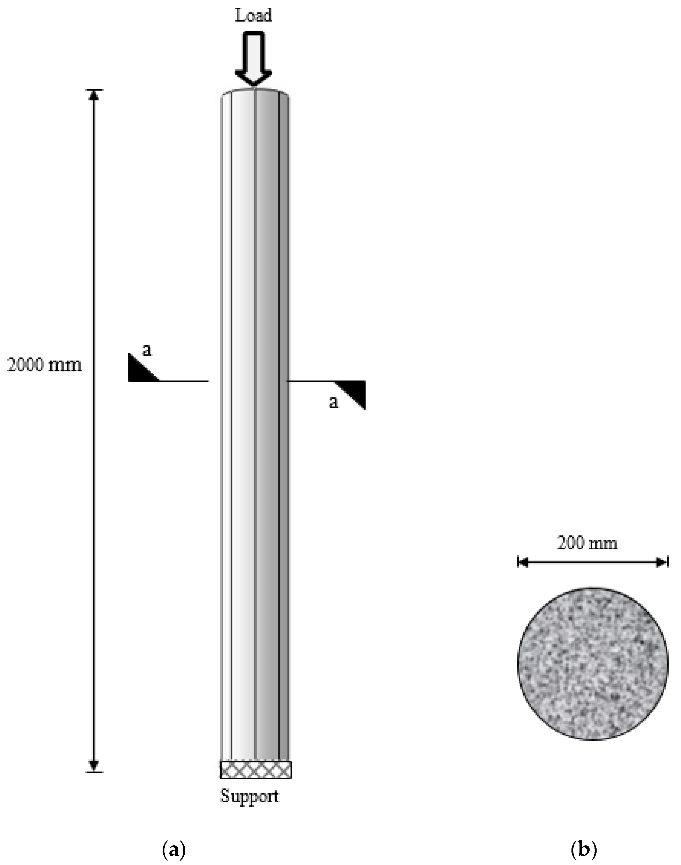
Figure 3.
Boundary conditions and details of the CFST column. (a) Elevation; (b) cross-section a–a.
Figure 3.
Boundary conditions and details of the CFST column. (a) Elevation; (b) cross-section a–a.
Figure 4.
Stress–strain curve of the steel material employed in the finite element models.
Figure 4.
Stress–strain curve of the steel material employed in the finite element models.
Figure 5.
Stress–strain relationship of the concrete material used in the finite element models.
Figure 5.
Stress–strain relationship of the concrete material used in the finite element models.
Figure 6.
Typical FE meshing sizes for the FE models.
Figure 6.
Typical FE meshing sizes for the FE models.
Figure 7.
Ultimate axial load vs. number of elements for the convergence study.
Figure 7.
Ultimate axial load vs. number of elements for the convergence study.
Figure 8.
Axial load–displacement curve for the circular FE model and existing experimental test.
Figure 8.
Axial load–displacement curve for the circular FE model and existing experimental test.
Figure 9.
Axial load–displacement for the circular and square CFST control models.
Figure 9.
Axial load–displacement for the circular and square CFST control models.
Figure 10.
Details of the FE CFST composite columns with different cross-sections and different CFRP layers number. (a) Details of the circular CFSTs with different CFRP layer numbers; (b) details of the square CFSTs with different CFRP layer numbers.
Figure 10.
Details of the FE CFST composite columns with different cross-sections and different CFRP layers number. (a) Details of the circular CFSTs with different CFRP layer numbers; (b) details of the square CFSTs with different CFRP layer numbers.
Figure 11.
Axial load–displacement curve for the control model and FE models with circular cross-sectional shape and different CFRP sheets.
Figure 11.
Axial load–displacement curve for the control model and FE models with circular cross-sectional shape and different CFRP sheets.
Figure 12.
Stress distribution for CFST models with different CFRP layers.
Figure 12.
Stress distribution for CFST models with different CFRP layers.
Figure 13.
Axial load–displacement curve for the control model and FE models with a square cross-sectional shape and different CFRP sheets.
Figure 13.
Axial load–displacement curve for the control model and FE models with a square cross-sectional shape and different CFRP sheets.
Figure 14.
Details of the FE CFST composite columns with different cross-sections and different CFRP confinement percentages. (a) Details of the circular CFSTs with different CFRP lengths; (b) details of the square CFSTs with different CFRP lengths.
Figure 14.
Details of the FE CFST composite columns with different cross-sections and different CFRP confinement percentages. (a) Details of the circular CFSTs with different CFRP lengths; (b) details of the square CFSTs with different CFRP lengths.
Figure 15.
Axial load–displacement curve for the control model and FE models with a circular cross-sectional shape and different CFRP confinements.
Figure 15.
Axial load–displacement curve for the control model and FE models with a circular cross-sectional shape and different CFRP confinements.
Figure 16.
Axial load–Displacement curve for the control model and FE models with a square cross-sectional shape and different CFRP confinements.
Figure 16.
Axial load–Displacement curve for the control model and FE models with a square cross-sectional shape and different CFRP confinements.
Figure 17.
Stress for the square CFST strengthened with/without CFRP sheets of different lengths.
Figure 17.
Stress for the square CFST strengthened with/without CFRP sheets of different lengths.
Figure 18.
General view of the experimental specimen and the FE model with a circular section after the test. (
a) Experimental failure mode, source: [
10]; (
b) FE failure mode, source: (the current study).
Figure 18.
General view of the experimental specimen and the FE model with a circular section after the test. (
a) Experimental failure mode, source: [
10]; (
b) FE failure mode, source: (the current study).
Table 1.
Details of experimental test (specimen one—LCSCI-1).
Table 1.
Details of experimental test (specimen one—LCSCI-1).
| Specimens | L
(mm) | D
(mm) | t
(mm) | Fcu
(MPa) | Ec
(MPa) | Fy
(MPa) | Es
(MPa) |
|---|
| LCSCI-1 | 2000 | 200 | 3.0 | 40.0 | 37,420 | 303.5 | 206,500 |
Table 2.
Element types assigned to each section of the FE models.
Table 2.
Element types assigned to each section of the FE models.
| Part of the FE Model | Element Type | Element Shape |
|---|
| Concrete | C3D8R | ![Buildings 14 00441 i001]() |
Steel tube
CFRP | S4R
S4R | ![Buildings 14 00441 i002]() |
Table 3.
Interaction types between components of CFST composite columns.
Table 3.
Interaction types between components of CFST composite columns.
| Surfaces | Interaction Type |
|---|
| Concrete–steel | Full tie interaction |
| Steel–CFRP | Cohesive behavior |
Table 4.
Steel material properties.
Table 4.
Steel material properties.
| Material | Poisson’s Ratio | Modulus of Elasticity (MPa) | Yield Strength (MPa) | Ultimate Strength (MPa) | Ultimate Strain |
|---|
| Steel | 0.3 | 206,500 | 303.5 | 400 | 0.05 |
Table 5.
Concrete material properties.
Table 5.
Concrete material properties.
| Material | Poisson’s Ratio | Modulus of Elasticity (MPa) | Compressive Strength (MPa) |
|---|
| Concrete | 0.2 | 37,420 | 40.0 |
Table 6.
CFRP material properties.
Table 6.
CFRP material properties.
| Material | Thickness
(mm) | Poisson’s Ratio | Modulus of Elasticity
(MPa) | Tensile Strength
(MPa) |
|---|
| CFRP | 1.2 | 0.4 | 240,000 | 1747 |
Table 7.
Details and properties of the experimental composite column in the existing study.
Table 7.
Details and properties of the experimental composite column in the existing study.
| Specimens | L
(mm) | D
(mm) | t
(mm) | Fcu
(MPa) | Ec
(MPa) | Fy
(MPa) | Es
(MPa) |
|---|
| Lcsc1-1 | 2000 | 200 | 3.0 | 40.0 | 37,420 | 303.5 | 206,500 |
Table 8.
Load, displacement, and deviation percentages for the FE model and the existing experimental test.
Table 8.
Load, displacement, and deviation percentages for the FE model and the existing experimental test.
| Label | Ultimate Axial Loading
(kN) | Displacement
(mm) | Deviation Percentages
(%) |
|---|
| Lcsc1-1 | 1818 | 5.5 | - |
| CM | 1841 | 5.8 | +1.2 |
Table 9.
Ultimate axial load, displacement, and deviation percentages for the control model and FE models with a circular cross-sectional shape and different CFRP sheet numbers.
Table 9.
Ultimate axial load, displacement, and deviation percentages for the control model and FE models with a circular cross-sectional shape and different CFRP sheet numbers.
| Label | Axial Loading
(kN) | Displacement
(mm) | Deviation Percentages
(%) |
|---|
| Cir-CM | 1841 | 5.8 | - |
| Cir-1.2 | 1998 | 5.7 | +8.5 |
| Cir-2.4 | 2275 | 5.7 | +23.5 |
| Cir-3.6 | 2488 | 5.6 | +35.1 |
| Cir-4.8 | 2660 | 5.4 | +44.5 |
Table 10.
Ultimate axial load, displacement, and deviation percentages for square cross-section models with different CFRP sheet numbers.
Table 10.
Ultimate axial load, displacement, and deviation percentages for square cross-section models with different CFRP sheet numbers.
| Label | Axial Loading
(kN) | Displacement
(mm) | Deviation Percentages
(%) |
|---|
| Squ | 1883 | 5.8 | - |
| Squ-1.2 | 1979 | 5.7 | +5.1 |
| Squ-2.4 | 2112 | 5.7 | +12.1 |
| Squ-3.6 | 2235 | 5.6 | +18.6 |
| Squ-4.8 | 2713 | 5.4 | +44.0 |
Table 11.
Ultimate axial load, displacement. and deviation percentages for circular cross-section FE models with different CFRP confinement lengths.
Table 11.
Ultimate axial load, displacement. and deviation percentages for circular cross-section FE models with different CFRP confinement lengths.
| Label | Axial Loading
(kN) | Displacement
(mm) | Deviation Percentages (%) |
|---|
| Cir-CM | 1841 | 5.8 | - |
| Cir-100% | 1998 | 5.7 | +8.50 |
| Cir-75% | 1927 | 5.7 | +4.60 |
| Cir-50% | 1843 | 5.6 | +0.10 |
| Cir-2 × 25% | 1842 | 5.6 | +0.05 |
Table 12.
Ultimate axial load, displacement, and deviation percentages for the control model and FE models with a square cross-sectional shape and different CFRP confinement percentages.
Table 12.
Ultimate axial load, displacement, and deviation percentages for the control model and FE models with a square cross-sectional shape and different CFRP confinement percentages.
| Label | Axial Loading
(kN) | Displacement
(mm) | Deviation Percentages
(%) |
|---|
| Squ-CM | 1883 | 5.8 | - |
| Squ-100% | 1979 | 5.7 | +5.10 |
| Squ-75% | 1934 | 5.7 | +2.71 |
| Squ-50% | 1885 | 5.6 | +0.11 |
| Squ-2 × 25% | 1884 | 5.6 | +0.05 |
| Disclaimer/Publisher’s Note: The statements, opinions and data contained in all publications are solely those of the individual author(s) and contributor(s) and not of MDPI and/or the editor(s). MDPI and/or the editor(s) disclaim responsibility for any injury to people or property resulting from any ideas, methods, instructions or products referred to in the content. |
© 2024 by the authors. Licensee MDPI, Basel, Switzerland. This article is an open access article distributed under the terms and conditions of the Creative Commons Attribution (CC BY) license (https://creativecommons.org/licenses/by/4.0/).


 ,
, 


