Abstract
Post-earthquake fire is considered as a catastrophic secondary disaster to personal and property safety, especially in complex rail transit station. This is primarily attributed to intricate infrastructure, densely populated floors, and the unrestricted layout of these areas. The aim of this study is to evaluate the evacuation capacity of complex railway stations under post-earthquake fires, and provide sustainable recommendations for building design. In this article, an evacuation assessment of a complex rail transit station under the post-earthquake fire for sustainable buildings was conducted from the internal environment and external rescue based on Building Information Modeling (BIM) and Fire Dynamic Simulation (FDS). The internal environment evacuation assessment simulation experiments were conducted in six hypothetical high-risk scenarios. In addition, the external rescue assessment was based on investigation of the route and the required rescue time during different periods of holidays and workdays. The results show that (1) The influence caused by different sizes of fire area in the power distribution room is smaller than those in the train at the platform floor. (2) In fire scenarios with the same fire area but different fire locations, the temperature is more affected than the CO concentration in the power distribution room. (3) It shows slight differences between single-floor fire and double-floor fire on evacuation of small area fire in power distribution room. Meanwhile, optimized design recommendations are proposed to reduce the risk of emergency evacuation in both internal and external environments of rail transit stations for sustainable future buildings, which include strategically locating the power distribution room away from public areas, installing fire-resistant doors around the room, increasing the quantity of smoke detectors and alarms with regular maintenance, minimizing the size of the power distribution room, developing specific emergency plans for train fires, and incorporating small fire stations in urban planning near complex public buildings to mitigate post-earthquake road obstruction challenges.
1. Introduction
Earthquakes are recognized as one of the most powerful and impactful natural disasters [1]. According to the statistics of the China Earthquake Networks, 12 Ms 8.0 earthquakes occurred around the world from 2012 to 2022, resulting in lots of casualties and economic losses [2]. In addition to direct losses, numerous secondary disasters after an earthquake, such as post-earthquake fire, also cause serious destructive consequences, including people injured, infrastructure damage, etc. [3]. The post-earthquake fires can be ignited due to various factors, such as broken gas pipes, open-flame sources, electrical short-circuits, leakage of flammable liquids, etc. [4]. Post-earthquake fires have been historically frequent, and each occurrence has resulted in catastrophic damage to the cities and buildings. For instance, on 17 January 1994, the Mw 6.7 Northridge earthquake in California caused ground cracks and approximately 110 fires directly attributed to its effects [5]. The Japan Kobe Ms 7.3 earthquake caused 269 fires due to natural gas leaking and 7036 buildings were destroyed in the post-earthquake fires in 1995 [6]. On 6 February 2023, Turkey was struck by two earthquakes, measuring Mw 7.8 and Mw 7.5, respectively, resulting in an estimated death toll of around 50,000 people. At the Port of Iskenderun, the earthquake caused a collapse of a part of containers, resulting in a fire that severely disrupted port operations. Post-earthquake fires can cause extensive damage to buildings, so it is essential to conduct evacuation assessments for providing sustainable improvements to buildings.
Nowadays, complex public spaces with multi-layer structures and high population density, such as rail transit stations, integrated railway transportation hubs, and airport terminals, have become increasingly prevalent [7]. The complex rail transit station facilitates people’s transportation and meets the needs of various commercial functions [8]. However, the complex structure, high population density on each floor, and the open nature of these spaces, pose significant challenge for evacuation in the post-earthquake fire [9]. According to statistics of the Ministry of Emergency Management of China’s Fire and Rescue Department, electrical fires have increased by 42.7% in the past 10 years [10]. Short circuit, poor electrical contacts, aging electrical equipment and overload are the main causes of electrical fires [11]. Due to lots of circuits and electrical equipment, complex urban public spaces are vulnerable to post-earthquake fires [9]. Emergency evacuation in complex urban public spaces, especially complex rail transit stations, has become a hot topic in recent years. Recently, targeted studies have been conducted on complex rail transit stations in some cities in China, such as Guangzhou, Xiamen, Chongqing, etc. The rail transit stations in these cities are relatively well-developed, with high traffic flow and complex infrastructure, which presents certain difficulties and challenges in emergency evacuation. To address these challenges, researchers have employed various methods including fluid dynamics, agent simulation, numerical simulation, and theoretical frameworks to conduct studies on emergency evacuation simulations [12,13,14]. Many studies have explored fire simulation in rail transit stations, but few have considered evacuation assessment in complex rail transit stations under post-earthquake fires. Post-earthquake fire rescue is usually more difficult than normal fire. The assessment of evacuation from post-earthquake fires is important for several reasons. Firstly, post-earthquake fires damage tends to be concentrated, and multiple fires can occur simultaneously. This poses unique challenges compared to other evacuation studies where fires may be more localized or isolated. Secondly, post-earthquake fires have the potential to cause large fire areas, which can quickly spread and pose a significant threat to human lives and property. Lastly, external rescue during post-earthquake fires can be particularly difficult due to the disruption of infrastructure and potential hazards present after an earthquake. Therefore, it becomes crucial to evaluate the response capabilities of complex rail transit stations to ensure effective evacuation procedures and facilitate sustainable design improvements for rail transit stations.
In recent years, many research have emerged in the field of fire research using different methods, including an emergency decision-making approach [15], crowd flow modeling [16], BIM-based simulation framework [17], systematic hybrid approach [18], etc. Researchers also have conducted a series of related studies regarding fires in rail transit stations from different perspectives, such as the emergency ventilation strategies [19], emergency response [20], the impact of the escalators and automatic ticket checkers [21], flow rate [22], and different door statuses (open and closed) [23]. However, post-earthquake fires have received relatively limited attention and in-depth research in the literature; thus, the need for more attention and in-depth research is obvious. Post-earthquake fires have been explored in various aspects, including the identification of fire-prone buildings using a risk matrix [24], the quantification of post-earthquake fire risks in densely populated urban areas [25], the exploration of simulation frameworks using BIM and VR [26], the finite element numerical analyses [4], and the framework for performance-based evaluation of fire engineering after earthquakes [27]. In addition, the development of a comprehensive method for the seismic damage assessment of sprinkler systems based on the combination of BIM, computational fluid dynamics (CFD) models, and fire dynamics simulator (FDS) programs has also been conducted [28]. According to the existing studies, BIM has been widely employed in post-earthquake fire simulation research. To analyze the virtual fire scenario, a more intuitive model could be built in BIM, allowing for the adjustment of various parameters.
The aim of this study is to address three critical research gaps in the field of fire simulation and emergency evacuation in complex rail transit stations. Firstly, there is a lack of research on evacuations ability assessment in these stations, resulting in a gap in sustainable building recommendations. Secondly, complex rail transit stations, which are characterized by multiple lines, intricate spatial structures, and high traffic flow, have received little attention in current research on fire simulations. Thirdly, post-earthquake fires have been relatively less considered in existing studies. Accordingly, comprehensive research on evacuations ability assessment of complex rail transit stations for post-earthquake fires is essential. By addressing these research objectives, this study aims to contribute to the development of safer and more resilient rail transit stations, ensuring the well-being and safety of passengers during post-earthquake fires. Accordingly, this research focuses on the evacuation assessment within the internal environment and external rescue of a complex rail transit station under the post-earthquake fire for sustainable. This research aims to (1) establish a fire simulation model based on BIM and Fire Dynamic Simulation (FDS) application, (2) conduct a case demonstration to verify the feasibility of the established model and assess the evacuation ability of the complex rail transit station, and (3) supply optimization design suggestions for the internal and external environment of the rail transit station to reduce risks in emergency evacuation.
2. Methodology
The research methodology consists of five modules: (1) Building Information Modeling (BIM), (2) Fire Dynamic Simulation (FDS), (3) assumptions in Revit and Pyrosim, (4) fire scenarios, and (5) fire simulation. The framework is shown in Figure 1, where the green background blocks represent specific research content and the purple graphics represent hypothesized fire scenarios.
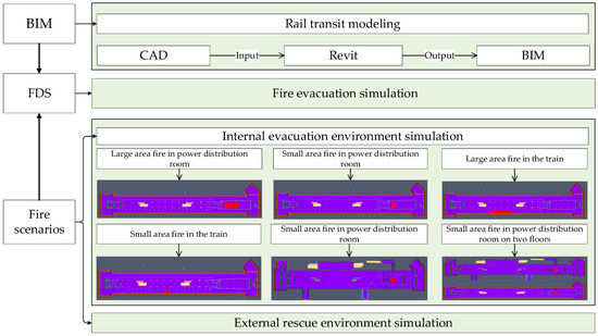
Figure 1.
Simulation framework.
2.1. BIM
BIM it is an important technology in the construction digitalization world, which can be used by adopting computer visualization technology and simulation method [29]. Based on BIM, buildings can be simulated by BIM to provide valuable management suggestions for subsequent operation and maintenance measures, such as emergency evacuation simulation in earthquake, fire, etc. [30]. It is crucial to gather information about the geometric characteristics of buildings for fire simulation and assessment. This includes accurately representing the following components:
- (1)
- Building structure, such as platform floors, concourse floors, entrances/exits, stairs, elevators, fire-resistant, as well as their quantity, dimensions, height, geometric shapes, position and orientation. This level of detail was particularly crucial for complex structures like a complex rail transit station.
- (2)
- BIM elements association. The relationships between different elements, such as the connection between the platform floor and stairs, elevators, and entrances/exits, should be considered in BIM elements association.
- (3)
- Ventilation and fire protection system. Determine the positioning and layout of ventilation and fire protection systems to ensure the safety of the railway transit station during fires. This involves factors such as smoke control devices, fire-extinguishing systems, fire doors, etc.Generally, non-graphical information is not required to be included in fire scenarios.
2.2. FDS
The Pyrosim software, developed by the American Institute of Standard Technology based on FDS, enables fire dynamic simulation. The stage of fire development involves a complex dynamic field generated by the interaction of coupled physical and chemical reactions, hydrodynamics, and heat transfer. It mainly follows the conservation equations, which are shown in Equations (1)−(4).
- (1)
- Mass conservation law:
- (2)
- Energy conservation law:
- (3)
- Momentum conservation law:
- (4)
- Gas component conservation law:
2.3. Assumptions in Revit and Pyrosim
It is assumed that the building structures suffer no considerable damage and the escape routes are not disrupted after the earthquake, at least for the first minutes of the a fire event [31]. In addition, the worst-case scenarios of non-structural damage such as elevator or fire-extinguishing system damage are considered. In addition, people evacuate rooms without closing fire-resistant doors, and non-fire-resistant doors are excluded from the model to focus on simulating critical fire and smoke emissions.
2.4. Fire Scenarios
The different locations of fire points in the complex rail transit station have different impacts on emergency evacuation. In order to better respond to emergencies and achieve sustainable future buildings, the most unfavorable principle should be applied in the fire site design. Combustible materials in rail transit station include various components, such as the trains bodies and some circuits [11]. Therefore, this paper mainly considers the locations that are most susceptible to fires: the train and the power distribution room. To provide a more comprehensive understanding of the fire risk in rail transit stations, the specific hypothetical ignition points are illustrated in the case study section. The fire simulation is divided into two parts: internal environment evacuation simulation and external environment rescue simulation.
2.4.1. Internal Evacuation Environment Simulation
The standard atmospheric pressure is 101,325 Pa and the relative humidity before the disaster was 50% without considering the influence of internal wind speed. To improve the detection of the temperature and CO concentration in the populated rail transit station after an earthquake, thermocouples and gas-phase devices are set at the populated area. According to Report on the Nutrition and Chronic Disease Status of Chinese Residents (2020), the average height of a male adult is stated to be 170.6 cm and for adult females is 158.7 cm [32]. Considering that the height of the human mouth and nose is lower than the height, the height of the thermocouple and gas-phase device are set lower than 170.6 cm on each floor. The two important parameters to consider are temperature and CO concentration.
- (1)
- Temperature
Human endurance to high temperatures is limited, particularly when it can cause irreversible damage to the skin and respiratory tract. To ensure the safety of the evacuees, the temperature must be maintained within a certain range. Research reveals that thermal burns to the respiratory tract can occur when individuals inhale air above 60 °C saturated with water vapor and the maximum exposure time is 10.1 min [33]. In this research, 60 °C is considered as a threshold value. Additionally, research indicates that humans can endure a maximum exposure time of 6 min at a temperature of 70 °C, and 3.8 min at 80 °C, which provide a reference for the following research [33].
- (2)
- CO Concentration
The primary threat to people’s life safety in a fire is the CO produced during the combustion process [31]. Furthermore, the proportion of hemoglobin (HB) in the form of carboxyhemoglobin (COHb) increases steadily as CO is inhaled causing HB to lose its ability to provide oxygen. Thus, the acute toxicity of CO depends mainly on the percentage of COHb [34]. Survival is rare in subjects with blood levels exceeding 50–60% COHb and 50% COHb is usually considered as an average lethal level [34]. According to research, when the CO concentration reaches 1600 ppm, the COHb concentration can reach 40–50%. Evacuees will exhibit symptoms of poisoning, including headache, tachycardia, dizziness, and nausea within 20 min. In severe cases, death can occur in less than 2 h [31,35]. Thus, 1600 ppm (1.6 × 10⁻³ mol/mol) is considered as a threshold value.
2.4.2. External Rescue Environment Simulation
External rescue, such as fire rescue and medical services, is necessary for all escapees [36]. Rail transit stations usually connect to the major urban roads with strong accessibility. This research investigates the route and the time required from the fire station to the complex rail transit station through the map during different periods of holidays and workdays for the evacuation assessment of the sustainable rail transit station in terms of external rescue.
3. Case Study
At present, there are many underground rail transit stations in China, and these stations are basically consistent in design principles. For instance, power distribution rooms, which are essential facilities, can be found in every rail transit station. It indicates that the design principles of rail transit stations are universally applicable. Trains and power distribution rooms may experience malfunctions or equipment failures during earthquakes, which can increase the risk of fire. Valuable insights and guidance can be obtained by considering similarities, consistency in design principles, and similarity in fire risk factors. Based on the above principles, a complex rail transit station with an underground two-floor structure was selected as the case study to provide research results that have reference value. The selected station is located at the intersection of two rail transit lines, which presents large area, high density passenger flow, and large numbers of power lines. Thus, the station shows applicability for fire simulation and evacuation assessment. The heights of the platform floor and concourse floor are 6.05 m and 5.15 m, respectively. In addition, the two floors are 181.2 m long and 20.7 m wide. Through field investigation, the station was found to have 37 fire-resistant doors and 9 wooden doors, which is shown in Table 1.

Table 1.
Types and location of doors.
Two staircases are available for the escaping from the platform floor to the concourse floor. In addition, four exits are available for escaping from the concourse floor to the outside. The plan of the two floors of the station is shown in Figure 2.
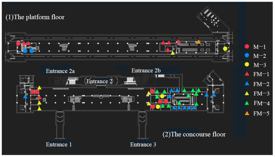
Figure 2.
Plan of a complex rail transit station in Beijing.
3.1. BIM Modeling and Pyrosim Software
In this research, the Revit 2016 was used for BIM modeling. The BIM model of the rail transit station case is shown in Figure 3. The building structure of the station include platform floors, concourse floors, entrances/exits, stairs, elevators, etc. In the case study of a complex rail transit station with an underground two-floor structure, the selected station is situated at the intersection of two rail transit lines. The platform floor of the rail transit station has a height of 6.05 m, while the concourse floor stands at 5.15 m. These floors span a length of 181.2 m and a width of 20.7 m. This configuration presents a large area, high density of passenger flow, and significant numbers of power lines, making it a suitable candidate for fire simulation and evacuation assessment.

Figure 3.
BIM model of the rail transit station case.
Rail transit stations encompass a multitude of interconnected elements. The rail transit station has two sets of stairs and escalators to facilitate movement between the platform floor and the concourse floor. Additionally, there is one elevator available on the platform floor to ensure accessibility for passengers with mobility needs. On the concourse floor, there are four entrances/exits to ensure convenient access and egress for passengers. Accurately documenting the associations between elements, such as the platform floor, stairs, elevator, and entrances/exits, within the BIM model is essential for maintaining consistency.
Ventilation systems are installed in public areas within the rail transit station case. The air intake in the public area of underground stations is directly taken from the atmosphere, and the exhaust is directly discharged from the ground. There are two stairs in the platform floor, several train doors on both sides, and four exits on the concourse floor, which are directly considered as natural ventilation openings. Fire hydrants are installed indoors at various locations within the station, including the concourse floor, the platform floor, the equipment areas, and pedestrian walkways. A Type II fire box is installed at the stairwell entrance of the public area on the platform floor, the equipment area on the platform floor. Fire hydrant pump start buttons are installed on each fire box, and an alarm button is installed outside the box. Type I fire boxes are used on the concourse floor, with staggered arrangements on both sides of the public area on the concourse floor.
The Pyrosim 2019 was used for building a FDS model, conducting simulation, and analyzing simulation results. The BIM model is exported in DWG format, and then imported into the Pyrosim software to transform the BIM model into a FDS model. The temperature and CO concentration are two main monitoring parameters in FDS.
3.1.1. Combustion Calculation Method
In the fire simulation, the actual fire combustion process can be more closely approximated by defining the combustion reactions and setting the relevant parameters such as products of fire combustion and heat release rate. The common way to determine the pyrolysis reaction in FDS is to determine the heat release rate (HRR) on a surface [31]. In this study, the heat release rate in per unit area (HRRPUA) are specified as the combustion calculation method in Pyrosim simulation.
3.1.2. “Surfaces” Parameters
The “Surface” parameters are used to define the properties of the solid objects and vents in FDS. For example, the “Burner” in the Surface parameter is used to define a fire, the “Layered” in the Surface parameter is to represent a solid and thermally conductive wall, and the “OPEN” in the Surfaces parameter is to represent a vent that is passively open to the outside and is often used to simulate an open door or window.
3.1.3. Detection Equipment Settings
Considering the damage of non-structural components such as fire extinguishing facilities, the locations of different fires in the complex rail transit station were determined. The detection devices include temperature detectors and CO detectors, both of which are set on the necessary escape routes, such as stairways, entrances, etc. The device numbers and locations are shown in Table 2 and Figure 4.
Table 2.
Devices number and location.
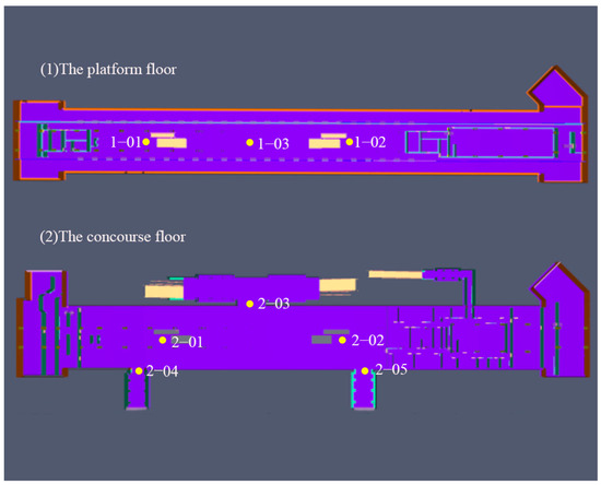
Figure 4.
The detectors location.
3.2. Fire Scenarios
When a fire occurs in an underground station, the smoke flow usually coincides with that of the normal passenger’s evacuation routes that will cause fatalities by asphyxiation [37]. In this research, two situations, the single-floor fire and the double-floor fire were considered. The six fire scenarios based on the size of the fire area are shown in Table 3.
Table 3.
Fire scenarios.
3.3. Internal Evacuation Environment Simulation Results
The time required for reaching the maximum CO concentration and the maximum temperature under the six fire scenarios are shown in Table 4 and Table 5, respectively. The simulation diagram of temperatures under different fire scenarios is shown in Figure 5.
Table 4.
The time required for reaching the maximum CO concentration.
Table 5.
The time required for reaching the maximum temperature.
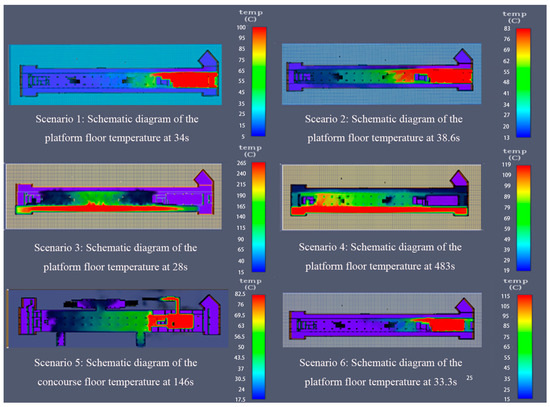
Figure 5.
Simulation diagram of temperatures under different fire scenarios.
3.3.1. Large Area Fire in Power Distribution Room at the Platform Floor
In the Scenario 1, both the CO concentrations at the platform floor and the concourse floor are below the threshold values (1.6 × 10⁻³ mol/mol), as shown in Figure 6. The CO concentrations and temperatures of the detected points increased from the initial values and eventually fluctuated around some values.

Figure 6.
CO concentrations and temperatures fluctuation trend under Scenario 1. (a) CO concentrations; (b) Temperature.
The platform floor:
(1−02): When the large area fire started in the power distribution room on the platform floor, the nearest stairway (1−02) firstly reaches the maximum CO concentration of 3.75 × 10⁻⁵ mol/mol and the maximum temperature of 30.2 °C at 34 s.
Then, the smoke continued to spread and reached the temperature of 68.1 °C, which lasted only 1 s and the highest CO concentration was 3.48 × 10⁻⁴ mol/mol at 175 s at the right stairway entrance (1−02).
The concourse floor:
(2−02): The smoke and fire spread rapidly to the upper floor through the stairway. The gap in the stairway makes the smoke gather rapidly at the right stairway (2−02). Thus, the time of reaching the peak at the right stairway of the concourse floor is shorter than that of the platform floor.
The highest CO concentration of 3.89 × 10⁻⁴ mol/mol and the highest temperature of 84 °C at the concourse floor were both reached at 81.3 s. In addition, the time above 60 °C lasted for only 3 s between 81 s and 83 s.
According to “2.4.1. Internal evacuation environment simulation”, the maximum exposure time is 3.8 min when the exposure temperature is 80 °C. The short duration of exceeding the threshold value means that the two stairway entrances (1−02) (2−02) near the distribution room have little impact on the escapees.
Therefore, it is escapable for the escapees in the Scenario1.
3.3.2. Small Area Fire in Power Distribution Room at the Platform Floor
In the Scenario 2, the CO concentrations and temperatures at the platform floor and concourse floor showed a gradual increase when small area fire in the power distribution room at the platform floor, as shown in Figure 7. The figures show that the CO concentrations at both the two floors did not exceed the threshold values.
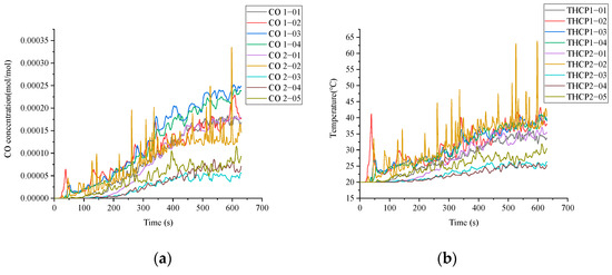
Figure 7.
CO concentrations and temperatures fluctuation trend under Scenario 2. (a) CO concentrations; (b) Temperature.
The platform floor:
(1−02): When the power distribution room were on fire, the nearest stairway (1−02) was the first reaching to the highest CO concentration of 6.44 × 10⁻⁵ mol/mol and the highest temperature of 41.2 °C at 38.6 s.
With the continuous diffusion of smoke, the platform floor reached its maximum CO concentration of 2.52 × 10⁻⁴ mol/mol and the maximum temperature of 43.20 °C at 609 s, both of which were lower than the threshold values.
The concourse floor:
(2−02): Smoke and fire spread rapidly to the upper floor through the stairway gap, resulting in the rapid accumulation of smoke at the right stairway (2−02). Therefore, the time to reach to the peak at the right stairway of the concourse floor was shorter than the platform floor.
In addition, the maximum CO concentration of 3.89 × 10⁻⁴ mol/mol at the concourse floor was reached at 81.32 s. And then, the second maximum CO concentration of 3.35 × 10⁻⁴ mol/mol at the concourse floor was reached at 595 s.
Later, the maximum temperature of 63.8 °C at the concourse floor was reached at 598 s, but only last for 2 s, which is lower than the maximum human endurance time of 10.1 min.
Thus, it is escapable for the escapees in the Scenario 2.
3.3.3. Large Area Fire in the Train
Large area fire in the train is considered the worst situation.
The platform floor:
As shown in Figure 8, the CO concentration and temperature of the detection points at the platform floor rapidly increased from 28 s to 59 s, and then gradually presented stable trend.

Figure 8.
CO concentrations and temperatures fluctuation trend under Scenario 3. (a) CO concentrations; (b) Temperature.
(1−03): In this scenario, the temperature in the middle of the platform floor (1−03) has reached 60 °C at 23 s, and then continued to rise over 200 °C. Additionally, CO concentration in the middle of the platform floor (1−03) has exceed 1600 ppm from 286 s to 289 s.
Under this condition, the escape presents high difficulties. The possibility that the escapees can escape smoothly under this condition is very small.
3.3.4. Small Area Fire in the Train
The platform floor:
As shown in Figure 9, the CO concentrations did not exceed the threshold value of 1600 ppm in the platform floor.

Figure 9.
CO concentrations and temperatures fluctuation trend under Scenario 4. (a) CO concentrations; (b) Temperatures.
(1−01): The highest CO concentration reached 7.17 × 10⁻⁴ mol/mol at 622 s, and the temperature of the stairway (1−01) reached to 60 °C at 330 s. Subsequently, the temperature of the platform floor gradually increased and the temperatures of every detector on the platform floor reached more than 60 °C from 330 s to 630 s. The maximum temperature of 104 °C at (1−01) was reached at 622 s.
The concourse floor:
As shown in Figure 9, both of the CO concentration and temperature at the concourse floor increased slowly and did not exceed the threshold value. The small area fire in the train has little impact on the concourse floor.
Thus, escaping in this situation is very difficult.
3.3.5. Small Area Fire in Power Distribution Room at the Concourse Floor
As shown in Figure 10, the CO concentration and temperature at multiple detection points at the platform floor present stable trend under Scenario 5. The fire had little impact on the platform floor, revealing a continuous increase in CO concentration and temperature at the detection points on the concourse floor.
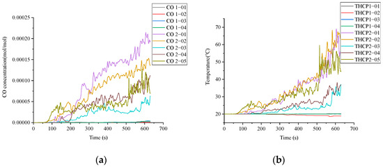
Figure 10.
CO concentrations and temperatures fluctuation trend under Scenario 5. (a) CO concentrations; (b) Temperature.
The concourse floor:
(2−05): The concourse floor entrance nearest to the fire starting point (2−05) firstly reached to the highest temperature of 27.6 °C and the highest CO concentration of 4.80 × 10⁻⁵ mol/mol at 146 s.
(2−02): With the continuous diffusion of smoke, the stairway nearest to the fire point (2−02) reached the maximum temperature of 27.4 °C and the maximum CO concentration of 4.90 × 10⁻⁵ mol/mol at 189 s.
(2−01) and (2−02): Later, the stairway (2−01) (2−02) reached 60 °C at the time of 597 s and 594 s, respectively. However, the duration that the temperature exceed 60 °C was very short, lasting only 21 s for stairway (2−01) and 34 s for stairway (2−02), respectively, and the maximum temperature at the concourse floor was 69 °C. According to “2.4.1. Internal evacuation environment simulation”, the human endurance time is 6 min when the temperature reaches 70 °C.
Therefore, it is escapable for the escapees in this scenario.
3.3.6. Simultaneous Small Area Fire in Power Distribution Room on the Two Floors
As shown in Figure 11, when a small area of the power distribution room on two floors catches fire simultaneously, the CO concentration and temperature at the detection points on both floors exhibit a gradual increase over time.
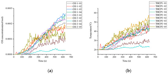
Figure 11.
CO concentrations and temperatures fluctuation trend under Scenario 6. (a) CO concentrations; (b) Temperature.
The platform floor:
(1−02): The stairway (1−02) nearest to the power distribution room on platform floor reached the highest temperature of 32.9 °C and the highest CO concentration of 9.85 × 10⁻⁵ mol/mol at 33.3 s.
(1−03): With the continuous diffusion of smoke, the middle position of the platform floor (1−03) reached the maximum temperature of 24 °C and the maximum CO concentration of 1.34 × 10⁻⁵ mol/mol at 69.3 s.
In addition, the maximum CO concentration of 2.65 × 10⁻⁴ mol/mol at the platform floor was reached at 607 s, and the maximum temperature of 47.4 °C at the platform floor was reached at 614 s.
The concourse floor:
(2−05): The nearest entrance to the fire starting location (2−05) reached the maximum temperature of 38 °C and the maximum CO concentration of 1.39 × 10⁻⁴ mol/mol at 199 s.
Additionally, the maximum CO concentration of 2.32 × 10⁻⁴ mol/mol at the concourse floor was reached at 614 s, and the maximum temperature of 57.5 °C at the concourse floor was reached at 619 s. It has been confirmed that both the maximum CO concentration and the maximum temperature were lower than the threshold value.
Thus, it is safe to escape in this scenario.
In summary, it becomes difficult to escape when large area fire or small area fire occurs in the train, which are Scenario 3 and Scenario 4. Comparatively, it is possible to escape in the Scenario 1, Scenario 2, Scenario 5 and Scenario 6 when the fire occurs in the power distribution room.
3.4. Influence of Fire Areas and Location
3.4.1. The Influence of Different Fire Areas
According to Section 3.3, the assessment results indicate that evacuation is feasible when a fire occurs in the power distribution room. However, evacuating becomes challenging when a fire breaks out on the platform floor of a train. Scenario 1, Scenario 2, Scenario 3, and Scenario 4 were selected for analyzing the influence of different fire areas on CO concentration and temperature. The stairway (1−02) nearest to the power distribution room on platform floor in Scenario 1 and Scenario 2 and the middle position of the platform floor (1−03) in Scenario 3 and Scenario 4 are considered for the analysis. The results of the CO concentrations and temperatures fluctuation trend are shown in Figure 12 and Figure 13. The difference of temperature and CO concentration in Scenario 1 and Scenario 2 are smaller than those in Scenario 3 and Scenario 4. Taking the example of 300 s, in Figure 12, the CO concentration is 1.53 × 10⁻⁴ mol/mol and the temperature is 37.3 °C under a large area fire, while under the small area fire is 9.3 × 10⁻⁵ mol/mol and 26.2 °C, respectively. As shown in Figure 13, the CO concentration is 7.59 × 10⁻⁴ mol/mol and the temperature is 225 °C under the large area fire, while the CO concentration is 1.59 × 10⁻⁴ mol/mol and the temperature is 48.7 °C under a small area fire. In this case, there is a difference of 6 × 10⁻⁴ mol/mol in CO concentration and 176.3 °C in temperature between the large area fire and the small area fire.
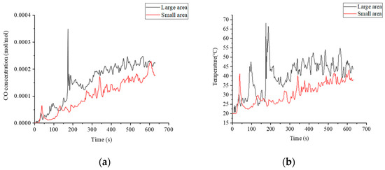
Figure 12.
CO concentrations and temperatures fluctuation trend of (1−02) under Scenario 1 and Scenario 2. (a) CO concentrations; (b) Temperature.
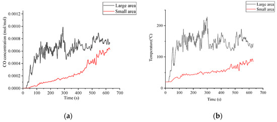
Figure 13.
CO concentrations and temperatures fluctuation trend of (1−03) under Scenario 3 and Scenario 4. (a) CO concentrations; (b) Temperature.
It can be seen that the CO concentration and temperature generated by large area fires are generally higher than those of small area fires. In addition, the influence caused by different size of the post-earthquake fire area in the power distribution room at the platform floor is smaller than those in the train at the platform floor. For a fire in the power distribution room, smoke can only flow through open doors, while for a fire in the train, smoke could enter the open space through all doors on the train.
3.4.2. The Influence of Different Fire Locations
In Scenario 2 and Scenario 5, although the fire areas are the same, the fire locations differ. In these two scenarios, the stairways nearest to the fire point (1−02) and (2−02) are chosen for analyzing. As shown in Figure 14, the CO concentration in (2−02) is lower than that in (1−02), and the difference in CO concentration between the two scenarios is 0.4 × 10⁻⁴ mol/mol at 630 s. As for temperature, the temperature in (1−02) is initially higher than that in (2−02), but the temperature increase rate in (2−02) is significantly greater than that in (1−02). Subsequently, the temperature becomes consistent at 177 s, and the final temperature in (2−02) is 23.6 °C higher than that in (1−02).

Figure 14.
CO concentrations and temperatures fluctuation trend of (1−03) under Scenario 2 and Scenario 5. (a) CO concentrations; (b) Temperature.
According to the results, the CO concentration presents consistent fluctuation trend for the small area fire in power distribution room in different floors of the station, while the temperature fluctuation show more obvious differences.
3.4.3. The Influence of Single-Floor Fire and Double-Floor Fire
To compare the different impact of single-floor fire and double-floor fire on evacuation, Scenario 2, Scenario 5, and Scenario 6 were selected with the same fire area for analysis. In this paper, (1−02) was selected as the analysis area to explore the difference between single-floor fire in Scenarios 2 and double-floor fire in Scenario 6. In addition, (2−02) was selected as the analysis area for Scenario 5 and Scenario 6.
The analysis results are shown in Figure 15. Regarding CO concentration, the increase rate in Scenario 2 and Scenario 6 is relatively consistent. At 630 s, the difference in CO concentration between the two scenarios is only 0.11 × 10⁻⁴ mol/mol. Regarding temperature, the temperatures show gradually increasing trend, and the temperature becomes consistent at 602 s. At 630 s, the temperature difference between Scenario 2 and Scenario 6 is only 9 °C. As shown in Figure 16, the CO concentrations in the two scenarios become the same at 83 s. Subsequently, the CO concentration in Scenario 6 is generally higher than that in Scenario 5. Finally, the CO concentration difference between Scenario 5 and Scenario 6 is 0.35 × 10⁻⁴ mol/mol at 630 s. In addition, the temperature in Scenario 6 is initially higher than that in Scenario 5, but the temperature increase in Scenario 5 is faster than that in Scenario 6. The temperatures become consistent at 542 s, and at 630 s, the temperature in Scenario 5 is 8.1 °C higher than that in Scenario 6.
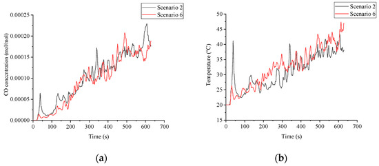
Figure 15.
CO concentrations and temperatures fluctuation trend of (1−02) under Scenario 2 and Scenario 6. (a) CO concentrations; (b) Temperature.
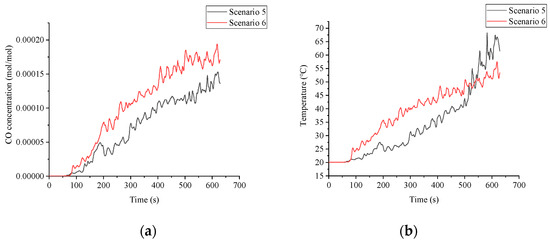
Figure 16.
CO concentrations and temperatures fluctuation trend of (2−02) under Scenario 5 and Scenario 6. (a) CO concentrations; (b) Temperature.
According to the above results, it shows slight differences of the influence on evacuation for small area fire in power distribution room on single-floor or double-floor.
3.5. External Rescue Environment Simulation Results
Through investigating the surrounding environment, two fire stations are 6.2 km and 4.2 km away from the complex rail transit station, as shown in Figure 17. The road condition from fire station A and fire station B to the complex rail transit station are observed though electronic map in all time of a day from “0:00” to “24:00”. It was found that the roads were consistently smooth on both workdays and holidays. Thus, the fire engine can smoothly travel from fire station A and fire station B to the complex rail transit station.
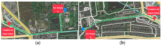
Figure 17.
Routes from two fire stations to the complex rail transit station. (a) Route from fire station A to the station; (b) Route from fire station B to the station.
In China, the planning and construction of urban fire stations are regulated by the “Code for Planning of Urban Fire Control GB 51080-2015” and “Construction Standards for Urban Fire Station 152-2017”. The “Construction Standards for Urban Fire Station 152-2017” indicates that the rescuers should arrive at the fire scene within 5 min after receiving the dispatch command. It is assumed that no surrounding collapsed houses and no traffic congestion on the roads after the earthquake. According to the real-time road condition analysis by the electronic map, a fire vehicle takes approximately 4 min and 3 min to reach the complex rail transit station from the fire station A and the fire station B, respectively. However, uncertainties such as weather and road conditions may arise during the firefighting vehicles moving from the fire station to the complex rail transit station. Due to the potential for damage to surrounding buildings, blocked access, and additional rescue tasks that fire stations must attend to after an earthquake, ensuring timely rescue is a considerable challenge.
4. Discussion
According to the research results, optimized design recommendations are proposed for reducing the risk of emergency evacuation in both internal and external environments of rail transit stations to achieve sustainable buildings.
4.1. Designing Power Distribution Room for Safety
The power distribution room in a complex rail transit station should be designed to be located away from public areas, such as stairwells or heavily trafficked corridors. It is recommended to set up the power distribution room in a relatively independent area, preferably on the concourse floor. This separation can help minimize the risk of fire spreading to public areas and provide easier access for maintenance personnel in case of emergencies.
To further quantify the risk reduction, this article takes the example of a small area fire in distribution room and demonstrates the effect of redesign the distribution room, which moves 8 m to the right based on the original design, as shown in Figure 18. The temperature and CO concentration at (2−02) have been measured. The results show that from 0 s to 630 s, the CO concentrations in the relocated power distribution room are lower than 1600 ppm (1.6 × 10⁻³ mol/mol), and the temperatures are below 60 °C. The highest CO concentration is 1.38 × 10⁻⁴ mol/mol at 589 s, and the highest temperature is only 45.2 °C at 620 s. Compare the (2−02) before and after the relocation, as shown in Figure 19. The difference in temperature is significantly greater than the difference in CO concentration.

Figure 18.
The original and relocated power distribution room of Scenario 5.
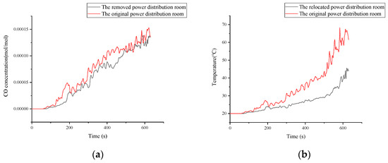
Figure 19.
CO concentrations and temperatures fluctuation trend of (2−02) under Scenario 5 before and after relocating power distribution room. (a) CO concentrations; (b) Temperatures.
In order to further explore the reduced risk of relocating the power distribution room away from public areas, this article compared the time required for the (2−02) to start heating up, reach the highest CO concentration, reach the highest Temperature before and after relocation, as shown in Table 6. According to the results, it can be seen that relocating the power distribution room 8 m away from the public areas reduces the risk by 23.23%, 9.8%, and 34.49%, respectively.
Table 6.
Risk reduction calculation.
4.2. Installing Fire-Resistant Doors
It is advisable to consider installing fire-resistant doors around the power distribution rooms. According to the “Fire Protection Design Standard for Subways” (GB51298−2018) in China, Class A fire-resistant doors should be installed at the entrances of firewalls, smoke-proof stairwells, refuge walkways, and connecting passages. Class B fire-resistant doors are recommended for the entrances of fire barriers, inspection doors in pipeline shafts, and evacuation doors in other areas. According to “Fire Doors” (GB 12955−2023) in China, Class A fire-resistant doors are required to have a minimum fire resistance and thermal insulation of 90 min, while Class B fire-resistant doors should have a minimum fire resistance and thermal insulation of 60 min.
While important position doors are replaced with fire-resistant doors, it can effectively prevent the spread of fire and reduce the risk of fire. These fire-resistant doors can act as barriers to prevent the spread of fire and smoke, ensuring that the impact of a fire accident remains localized and does not compromise the safety of passengers or critical infrastructure. Therefore, replacing the doors with fire-resistant doors may greatly reduce the risk of a post-earthquake fire.
4.3. Improving Fire Detection Systems
Enhancing the safety of complex rail transit stations requires an increased quantity of smoke detectors and alarms, especially in high-risk areas like power distribution rooms and trains. Regular maintenance and testing of these detection systems are crucial to ensure their effectiveness at detecting and alerting occupants to potential fire accidents promptly. It is recommended to apply the latest digital technologies to establish intelligent protection systems, such as fire detection and alarm system based on image processing. Real-time monitoring of the detection environment through cameras and regular collection of image information is suggested to be implemented. Combining with computer information processing and automatic image recognition technology, the implementation of a fire alarm system could achieve automation and intelligence of fire detection and alarm.
4.4. Optimizing Power Distribution Room Design
When considering the design and layout of the power distribution room, it is important to recognize that a large area fire can have a more significant impact than a small area fire. As shown in Figure 12, a comparison is made between Scenario 1 and Scenario 2. The large area fire has the highest CO concentration and temperature at 187 s. Specifically, the CO concentration in the large area fire is 1.72 × 10⁻⁴ mol/mol with a temperature of 66.4 °C, whereas the CO concentration in the small area fire is 4.58 × 10⁻⁵ mol/mol with a temperature of 24.7 °C. It can be seen that the temperature and CO concentration of a large area fire are obviously higher than those of a small area fire. In addition, the time to exceed the threshold of 60 °C is 10.1 min. Therefore, if the area of the power distribution room is reduced as much as possible, it can effectively slow down the speed of fire spread and reduce the risk of fire. A smaller distribution room area means fewer combustibles and combustion products, which can reduce the possibility of fire spreading. In addition, reducing the area of the power distribution room can also reduce the impact of fires on important facilities and public safety with-in the station. Therefore, efforts should be made to minimize the area of the power distribution room wherever possible.
4.5. Developing Emergency Plans for Train Fires
It has shown that the consequences of a fire occurring within a train are typically more severe than those originating in a power distribution room. As shown in Figure 12 and Figure 13, the temperature and CO concentration differences between Scenario 1 and Scenario 2 are smaller than those between Scenario 3 and Scenario 4. The results show that it is often difficult for people to escape during train fires. In order to avoid train fire accidents, it is crucial to develop specific emergency plans and response strategies tailored to train fires. This may involve specialized evacuation procedures, the installation of fire suppression systems, and training programs for staff to effectively manage such accidents and ensure the safety of passengers.
4.6. Establishing Additional Small Fire Stations
In urban planning considerations, it is recommended to incorporate the establishment of additional small fire stations around complex public buildings in different areas within the city. This proactive measure helps to ensure that there are sufficient fire-fighting resources readily available in an earthquake or other emergencies. By strategically locating these fire stations, potential road obstruction issues can be mitigated, enabling quicker response times and reducing the overall impact of fires on critical infrastructure and public safety.
5. Conclusions
Post-earthquake fires have a significant impact on personal and property safety. This research conducted an evacuation assessment of complex rail transit station under post-earthquake fires for sustainable buildings based on BIM and FDS. By establishing a fire simulation model based on BIM and FDS, this paper assessed the feasibility of evacuation in a complex rail transit station under post-earthquake fires through monitoring temperature and CO concentration. In addition, this paper considered external factors related to disaster relief to determine whether external rescue forces can promptly arrive at the complex rail transit station to provide rescue coverage. According to the research, six optimized design recommendations were discussed to reduce the risk of emergency evacuation in both internal and external environments of rail transit stations for sustainable future buildings.
However, the study did not discuss the optimal evacuation routes for passengers. Chaotic conditions can hinder a safe and efficient evacuation, thereby increasing the risk of injuries or casualties. Therefore, as a future research direction, it is crucial to develop reasonable passenger escape route plans specifically tailored for complex rail transit stations under a post-earthquake fire. This would help address the limitations of the current study and enhance the overall emergency preparedness and response strategies in such critical scenarios. Moreover, examining the effectiveness of evacuation strategies through simulations or conducting field studies to analyze real-world evacuation scenarios could provide valuable insights for improving the safety and resilience of urban buildings facing post-earthquake fires.
Author Contributions
Conceptualization, H.X., Y.W. and Q.Z.; methodology, H.X., Y.W. and Y.T.; software, H.X. and Y.W.; validation, Y.W.; formal analysis, H.X., Y.W. and Q.Z.; investigation, H.X., Y.W. and Q.Z.; resources, H.X., Y.W. and Y.T.; data curation, H.X. and Y.W.; writing—original draft, Y.W., Y.T. and Q.Z.; writing—review and editing, Y.T. and Q.Z.; visualization, Y.W.; project administration, H.X.; funding acquisition, H.X. All authors have read and agreed to the published version of the manuscript.
Funding
This research was funded by The General Project of Chongqing Natural Science Foundation (Grant No. cstc2021jcyj-msxmX0951); The Western Project of the National Social Science Fund of China (Grant No. 22XGL013); The China Postdoctoral Science Foundation (Grant No. 2021M700617); and The Innovative Project of Chongqing Oversea Study Innovation Program (Grant No. cx2020035).
Data Availability Statement
The data presented in this research are available upon request from the corresponding author. The data are not publicly available due to privacy.
Conflicts of Interest
Author Hui Xu was employed by the company Chongqing Innovation Center of Industrial Big-Data Co., Ltd. The remaining authors declare that the research was conducted in the absence of any commercial or financial relationships that could be construed as a potential conflict of interest.
References
- Lou, T.; Wang, W.; Li, J. Post-earthquake fire behaviour of a self-centring connection with buckling-restrained plates and pre-stressed bars: An experimental investigation. J. Build. Eng. 2022, 56, 104733. [Google Scholar] [CrossRef]
- Historical Query of China Earthquake Networks Center. China Earthquake Networks Center. Available online: http://www.ceic.ac.cn/history (accessed on 24 November 2023).
- Ni, S.; Birely, A.C. A simplified model for the post-fire earthquake flexural response of reinforced concrete walls with boundary elements. Eng. Struct. 2018, 175, 721–730. [Google Scholar] [CrossRef]
- Risco, G.V.; Zania, V.; Giuliani, L. Numerical assessm3.ent of post-earthquake fire response of steel buildings. Saf. Sci. 2023, 157, 105921. [Google Scholar] [CrossRef]
- Trifunac, M.D.; Todorovska, M.I. The Northridge, California, earthquake of 1994: Fire ignition by strong shaking. Soil Dyn. Earthquake Eng. 1998, 17, 165–175. [Google Scholar] [CrossRef]
- Nishino, T. Probabilistic analysis of the vulnerability of fire departments to ignitions following megathrust earthquakes in the Nankai Trough subduction zone, Japan. Fire Saf. J. 2021, 120, 103038. [Google Scholar] [CrossRef]
- Xu, H.; Li, Y.; Wang, L. Resilience Assessment of Complex Urban Public Spaces. Int. J. Environ. Res. Public Health 2020, 17, 524. [Google Scholar] [CrossRef]
- Li, M.; Wang, Y.H.; Jia, L.M. On operation safety assessment model for urban rail transit station. Adv. Transp. Stud. 2015, 1, 13–22. [Google Scholar]
- Xu, H.; Xue, B. Key indicators for the resilience of complex urban public spaces. J. Build. Eng. 2017, 12, 306–313. [Google Scholar] [CrossRef]
- Zhang, J.; Chen, T.; Su, G.; Li, C.; Zhao, F.; Mi, F. Microstructure and component analysis of glowing contacts in electrical fire investigation. Eng. Fail. Anal. 2022, 140, 106539. [Google Scholar] [CrossRef]
- Sarreshtehdari, A.; Khorasani, N.E. Integrating the fire department response within a fire following earthquake framework for application in urban areas. Fire Saf. J. 2021, 124, 103397. [Google Scholar] [CrossRef]
- Feng, J.; Gai, W.; Yan, Y. Emergency evacuation risk assessment and mitigation strategy for a toxic gas leak in an underground space: The case of a subway station in Guangzhou, China. Saf. Sci. 2021, 134, 105039. [Google Scholar] [CrossRef]
- Chen, Y.; Wang, C.; Yap, J.B.H.; Li, H.; Zhang, S. Emergency evacuation simulation at starting connection of cross-sea bridge: Case study on Haicang Avenue Subway Station in Xiamen Rail Transit Line. J. Build. Eng. 2020, 29, 101163. [Google Scholar] [CrossRef]
- Xu, H.; Tian, C.; Li, Y. Emergency Evacuation Simulation and Optimization for a Complex Rail Transit Station: A Perspective of Promoting Transportation Safety. J. Adv. Transp. 2020, 2020, 8791503. [Google Scholar] [CrossRef]
- Wang, Y.; Liang, Y.; Sun, H.; Yang, Y. Decision-making for fire emergency of urban rail transit based on prospect theory. Math. Probl. Eng. 2021, 2021, 3414589. [Google Scholar] [CrossRef]
- Huang, D.; Lo, S.; Chen, J.; Fu, Z.; Zheng, Y.; Luo, L.; Zhuang, Y.; Cheng, H.; Yang, L. Mapping fire risk of passenger-carried fire load in metro system via floor field cellular automaton. Autom. Constr. 2019, 100, 61–72. [Google Scholar] [CrossRef]
- Sun, Q.; Turkan, Y. A BIM-based simulation framework for fire safety management and investigation of the critical factors affecting human evacuation performance. Adv. Eng. Inf. 2020, 44, 101093. [Google Scholar] [CrossRef]
- Zhang, L.; Wu, X.; Liu, M.; Liu, W.; Ashuri, B. Discovering worst fire scenarios in subway stations: A simulation approach. Autom. Constr. 2019, 99, 183–196. [Google Scholar] [CrossRef]
- Long, Z.; Zhong, M.; Chen, J.; Cheng, H. Study on emergency ventilation strategies for various fire scenarios in a double-island subway station. J. Wind Eng. Ind. Aerodyn. 2023, 235, 105364. [Google Scholar] [CrossRef]
- Liu, Q.; He, R.; Zhang, L. Simulation-based multi-objective optimization for enhanced safety of fire emergency response in metro stations. Reliab. Eng. Syst. Saf. 2022, 228, 108820. [Google Scholar] [CrossRef]
- Wang, C.; Song, Y. Fire evacuation in metro stations: Modeling research on the effects of two key parameters. Sustainability 2020, 12, 684. [Google Scholar] [CrossRef]
- Qin, J.; Liu, C.; Huang, Q. Simulation on fire emergency evacuation in special subway station based on Pathfinder. Case Stud. Therm. Eng. 2020, 21, 100677. [Google Scholar] [CrossRef]
- Peng, M.; Shi, L.; He, K.; Yang, H.; Cong, W.; Cheng, X.; Richard, Y. Experimental study on fire plume characteristics in a subway carriage with doors. Fire Technol. 2020, 56, 401–423. [Google Scholar] [CrossRef]
- Juliá, P.B.; Ferreira, T.M.; Rodrigues, H. Post-earthquake fire risk assessment of historic urban areas: A scenariobased analysis applied to the Historic City Centre of Leiria, Portugal. Int. J. Disaster Risk Reduct. 2021, 60, 102287. [Google Scholar] [CrossRef]
- Sarreshtehdari, A. The Impact of Fire Following Earthquake on Urban Environment considering the Seismic Performance of Infrastructure Networks. Ph.D. Thesis, State University of New York at Buffalo, Buffalo, NY, USA, 2021. [Google Scholar]
- Lu, X.; Yang, Z.; Xu, Z.; Xiong, C. Scenario simulation of indoor post-earthquake fire rescue based on building information model and virtual reality. Adv. Eng. Softw. 2020, 143, 102792. [Google Scholar] [CrossRef]
- Lou, T.; Wang, W.; Izzuddin, B.A. A framework for performance-based assessment in post-earthquake fire: Methodology and case study. Eng. Struct. 2023, 294, 116766. [Google Scholar] [CrossRef]
- Xu, Z.; Zhang, Z.; Lu, X.; Zeng, X.; Guan, H. Post-earthquake fire simulation considering overall seismic damage of sprinkler systems based on BIM and FEMA P-58. Autom. Constr. 2018, 90, 9–22. [Google Scholar] [CrossRef]
- Zhang, W.; Liu, Y.; Yu, S.; Zhang, Y.; Yang, L.; Qi, L. The Application Research of BIM Technology in the Construction Process of Yancheng Nanyang Airport. Buildings 2023, 13, 2846. [Google Scholar] [CrossRef]
- Deng, H.; Wei, X.; Deng, Y.; Pan, H.; Deng, Q. Can information sharing among evacuees improve indoor emergency evacuation? An exploration study based on BIM and agent-based simulation. J. Build. Eng. 2022, 62, 105418. [Google Scholar] [CrossRef]
- Lotfi, N.; Behnam, B.; Peyman, F. A BIM-based framework for evacuation assessment of high-rise buildings under post-earthquake fires. J. Build. Eng. 2021, 43, 102559. [Google Scholar] [CrossRef]
- Report on the Nutrition and Chronic Disease Status of Chinese Residents; The State Council Information Office of the People’s Republic of China: Beijing, China, 2022.
- NFPA13; Standard for the Fixed Guideway Transit and Passenger Rail Systems. National Fire Protection Association: Quincy, MA, USA, 2020.
- Purser, D.A.; McAllister, J.L. Assessment of Hazards to Occupants from Smoke, Toxic Gases, and Heat. In SFPE Handbook of Fire Protection Engineering, 5th ed.; Springer: New York, NY, USA, 2016; pp. 2308–2428. [Google Scholar]
- Goldstein, M. Carbon monoxide poisoning. J. Emerg. Nurs. 2008, 34, 538–542. [Google Scholar] [CrossRef] [PubMed]
- Hahne, D.; Rehm, S. Full-scale tests of external rescue with firefighters in underground stations. Fire Saf. J. 2022, 128, 103538. [Google Scholar] [CrossRef]
- Yang, H.; Li, S. Numerical Investigation on the Effect of Mobile Smoke Ventilator on Fire-induced Smoke Extraction for Underground Platform in a High-speed Railway Station. Procedia Eng. 2018, 211, 871–880. [Google Scholar] [CrossRef]
Disclaimer/Publisher’s Note: The statements, opinions and data contained in all publications are solely those of the individual author(s) and contributor(s) and not of MDPI and/or the editor(s). MDPI and/or the editor(s) disclaim responsibility for any injury to people or property resulting from any ideas, methods, instructions or products referred to in the content. |
© 2024 by the authors. Licensee MDPI, Basel, Switzerland. This article is an open access article distributed under the terms and conditions of the Creative Commons Attribution (CC BY) license (https://creativecommons.org/licenses/by/4.0/).