Article

Experimental and Numerical Investigation on Flexural Strengthening of Precast Concrete Corbel Connections with Fiber-Reinforced Plastic Sheet

1
Department of Structural Engineering, AlphaPlex Consulting Ltd., Langley, BC V1M 2J9, Canada
2
School of Engineering, The University of British Columbia, Kelowna, BC V1V 1V7, Canada
*
Author to whom correspondence should be addressed.
Buildings 2024, 14(2), 387; https://doi.org/10.3390/buildings14020387
Submission received: 30 December 2023 / Revised: 21 January 2024 / Accepted: 29 January 2024 / Published: 1 February 2024

Abstract

:
This paper presents the results of experimental and numerical investigations aimed at enhancing the flexural capacity of Precast Concrete Corbel Beam–Column Connections (PC-CBCCs) using Fiber-Reinforced Plastic (FRP) sheets. The experimental study primarily focused on assessing the flexural capacity of pinned PC-CBCCs reinforced with FRP layers, comparing them to a moment-resisting connection. A series of half-scale specimens, including three PC-CBCCs with varying FRP configurations, were tested alongside one in situ concrete fixed connection. The first specimen (PC-1) utilized L-shaped and full-wrap FRPs, whereas PC-2 and PC-3 employed both U-shaped and full-wrap layers. The objective is to quantify the ultimate flexural capacity of PC-CBCCs reinforced by FRP sheets. In PC-3, the external anchorage is introduced to assess its influence on delaying the FRP layer debonding under lateral loading. The effects of the FRP layer thickness, locations, and potential debonding are examined under unidirectional static tests while applying a constant axial compressive load to the columns and subjecting the beams to lateral loads until fracture. The test results illustrate that strengthening the corbel connection with L-shaped FRP or spiral U-shaped FRP sheets without mechanical anchorage cannot result in a significant bending capacity due to debonding. However, with the incorporation of mechanical anchors, the connection manages to enhance the moment capacity to 81% of a fixed connection’s flexural capacity. Additionally, a finite element model of the PC-CBCCs and a fixed joint is developed to simulate nonlinear static analyses of the connections using ANSYS 19.2 software. The simulation model is precise in predicting the initial stiffness and ultimate capacity of the beam–column joints, as verified by the experimental results. A comprehensive comparison is conducted to determine their responses by employing various FRP configurations and properties. Moreover, design parameters such as bond length and thickness of the FRP sheets, along with appropriate mechanical anchorage, are identified as effective in preventing debonding, and delamination. However, wrapping the beam far away from the joint interface has a minimal impact on the failure mode, stress reduction, and load-bearing capacity.

1. Introduction

Precast reinforced concrete structures have gained widespread popularity due to their numerous advantages, including superior quality control, rapid construction speed, reduced labor requirements, and lower construction costs. Many types of precast concrete components can be used in different structural systems and applications. These include beam–column connections [1,2,3]; precast beams; and girders that are double-tee, inverted-tee, L-shaped, I-shaped, and box-shaped [4], which are horizontal members that span between columns or walls and support floors or roof slabs. Precast concrete columns and walls [5,6] that are rectangular, circular, octagonal, H-shaped, and C-shaped are vertical members that support beams, girders, or slabs and provide stability and lateral resistance to the structure. Precast concrete floors [7] are horizontal members that form a structure with common hollow-core, solid, ribbed, waffle, and coffered slabs. Each of these components can be either prestressed or reinforced with cast-in-place concrete, steel plates, or Fiber-Reinforced Plastic (FRP) sheets [8,9].
In precast concrete structures, the connections between elements are pivotal during severe wind and seismic loadings. These connections are broadly categorized into two types: wet and dry connections [10,11]. Wet connections involve the use of protruding reinforcement bars from the precast concrete components and the application of cast-in-place concrete [12]. These connections exhibit a seismic performance akin to monolithic joints, demonstrating good energy dissipation and bearing capacity [13]. The dry connections either are pinned connections or rely on high-strength bolts and steel plates [14]. Dry connections offer time-efficient assembly and ease of construction, making them commonly used in precast structures. However, these connections, particularly those with pinned types, can have low flexural capacity and ductility, which allow beams to rotate freely without effectively transferring lateral forces to columns [15,16]. This deficiency in rotational capacity to dissipate seismic energy absorption can lead to significant damage during seismic events in precast structures [17]. Hence, researchers are investigating methods to transform these pinned connections into flexural joints, aiming to enhance the structures’ performance against both gravitational and lateral loads.
There are several techniques to increase the resilience of the pinned precast connections by employing replaceable energy dissipation connectors [18], FRP [19], end plate and bolted connections [20,21], dowel bars [22], steel billets [23], steel box sections [24], etc. These connectors can improve the seismic performance of the precast structure and make post-earthquake repair more convenient. This paper aims to enhance the seismic performance of a Precast Concrete Corbel Beam–Column Connection (PC-CBCC) with FRP sheets and appropriate mechanical anchorage. The FRP materials are known for their high strength-to-weight ratio and excellent corrosion resistance, making them suitable for use in seismic retrofitting of existing structures [25]. Through the confinement of concrete members, the flexural, shear, and axial capacities of the reinforced concrete elements can be increased, thereby enhancing energy absorption [26]. The FRP sheets and bars exhibit significantly greater strength and resistance against corrosion, along with enhanced re-moldability, when compared to steel materials. Furthermore, in the exploration of alternative fiber-reinforced composites for structural reinforcement, Carbon Fiber-Reinforced Polymer (CFRP) emerges as the preferred material when high mechanical properties, including elevated strength and stiffness, coupled with fatigue resistance and superior corrosion resistance, are imperative for meeting stringent bearing performance requirements. Conversely, Basalt Fiber-Reinforced Polymer (BFRP) and Glass Fiber-Reinforced Polymer (GFRP) find frequent applications as internal reinforcement in concrete members, presenting themselves as economically sound alternatives. These materials are strategically employed in scenarios where cost considerations and lower bearing performance thresholds take precedence, playing a fundamental role in addressing the challenge of insufficient durability in concrete structures caused by the corrosion of steel bars [27,28]. Moreover, they contribute to enhancing the bearing capacity of concrete structures, capitalizing on the high strength of FRP. Particularly, GFRP offers attributes such as high strength, water resistance, chemical resistance, and cost-effectiveness, rendering it essential for corrosion-resistant properties and common usage in flexural members. Noteworthy is the fact that GFRP bars exhibit high strength without a yield point, challenging the conventional characterizations of ductility in determining the ductility of GFRP-reinforced concrete components. Each of these materials possesses distinct advantages, enabling informed choices based on the specific requirements of the reinforcement project. In the context of this paper, the focus is on delving into the application of FRP material in precast concrete corbel connections, shedding light on their extensive applications in structural engineering.
Over the past decades, extensive research has focused on reinforcing cast in situ beam–column connections using FRP and other techniques [29,30,31]. However, several aspects concerning the identification and mitigation of weaknesses in precast connection details when exposed to lateral loads remain unexplored [32]. The primary drawbacks associated with precast connections involve shear–moment failure due to an inadequate bond length and a lack of diagonal shear strength within the connection core. Gergely et al. [33] and the research conducted by Parvin and Granata [34] focused on improving the shear–moment capacity of corbel T-joint connections using CFRP composites. Gergely and his team performed fourteen tests on one-third connections, taking into account factors such as the composite configuration, direction of the fiber orientation, and treatment of the surface. The results highlighted the efficacy of carbon FRP material in enhancing the shear capacity of beam–column joints. It was observed that fibers inclined at 45 degrees in the joint region were the most effective, aligning with the direction of the principal planes. The separation of these angled FRP sheets was observed to initiate from both the upper and lower portions of the joint, emphasizing the importance of securing proper anchorage. Moreover, multiple investigations [35,36] have explored reinforcing beam–column connections through the use of FRP separation. Harmon and collaborators [36] specifically delved into the influence of the adhesive layer positioned between polymer and a concrete surface. They formulated the delamination response of the model of the FRP and validated it through experimental tests. They concluded that the proper design of the bond layer can significantly improve the bond strength. Tumialan et al. [37] tested 14 simply supported beams reinforced with both steel and CFRP strips. Four of the tests are discussed in the text, and all the beams were 152.4 mm wide × 304.8 mm deep and reinforced with four No. 5 bars. The four beams spanned 2133.6 mm, with the shear span estimated to be 914.4 mm. They were reinforced with CFRP strips with a nominal thickness of 0.165 mm per layer. The concrete strength was not reported in this study but was assumed to be 37.9 MPa for analysis. The study identified two failure modes: the first mode corresponded to the cover delamination initiated at the FRP termination point located at the beam support, while the second mode initiated approximately 609.6 mm from the support, along with delamination of the FRP from the concrete originating from the point of the cover delamination and proceeding to the support. Harmon et al. [36] compared their design theory with failure mode I of the test results. Moreover, they evaluated failure mode II by comparing the analytical value of the peeling strength with the computed experimental value. This comparison showed that failure mode II was initiated by the peeling of the FRP from the critical section to the support followed by cover delamination from the critical section toward the center of the beam. Tumialan and his team [37] carried out experiments on fourteen beams with boundary conditions strengthened by the integration of CFRP and steel. The study identified two delamination modes of failure: (I) initiated at the end of the FRP and (II) 609.6 mm from the support. Harmon et al. [36] validated their design theory by comparing it with the collapse mode I of the experimental results. They also evaluated failure mode II by comparing the theoretical debouncing capacity with the test data. This comparison showed that mode II was started by the separation of the polymer sheets from the critical zones.
However, the existing knowledge regarding enhancing the flexural capacity of pinned precast connections is limited to specific cases, highlighting the need for further analysis and investigation. To address this, this study encompasses comprehensive experimental and numerical investigations to explore the application of FRP sheets. Its primary aim is to enhance the understanding of transforming pinned precast concrete connections into moment-resistant ones. The feasibility of this transformation involves employing various bonding methods, such as wrapping corbels and focusing on the critical zones of beams and columns. The study seeks to increase our knowledge regarding the feasibility of using FRP sheets to alter the structural behavior from pinned to moment-resistant connections.
The subsequent sections introduce the experimental testing program, encompassing descriptions of the specimens, preparation of the test archetypes, material properties, and test setup, along with the instrumentation details. Following this, the experimental results are presented to demonstrate the effectiveness of the FRP layers in enhancing the flexural capacity of the PC-CBCC. Subsequently, the numerical modeling of both fixed and pinned connections employing various wrapping methods is simulated, and the obtained results are compared across a comprehensive set of illustrative examples.

2. Experimental Testing Program

2.1. Description of the Test Specimens

In this study, four 1/2-scaled specimens, serving as representative examples of exterior beam–column connections in a building, were designed and tested. The prototypes included a moment-resisting (fixed) connection with cast in situ concrete, referred to as ‘FC’, and PC-CBCC, designated as ‘PC’. Figure 1 illustrates the details of the FC and PC specimens. Both FC and PC prototypes were designed per the weak beam–strong column theory, as per ACI 318 [38]. The longitudinal reinforcement ratio for the beams in their cross-sectional area was set at 0.3 of the maximum ratio of reinforcement (0.3ρmax), while the longitudinal bars for the columns were established at 3.5%. Their transverse bars and bond lengths were also designed to comply with the ACI 318 requirements for earthquake-prone regions. As depicted in Figure 1, unlike the FC specimen, the PC archetypes featured pinned joints, wherein the beam rested on the corbel of the column, and the space between them was filled with cement grout.

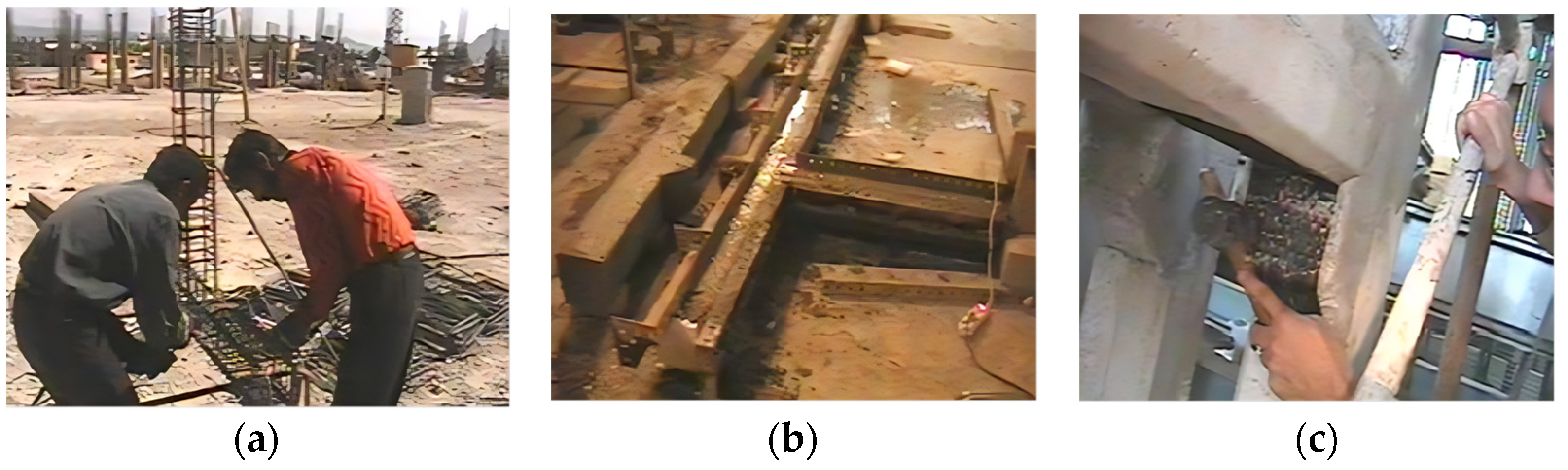
2.2. Preparation of the Test Archetypes

The concrete mix design for the beam–column connections followed the specifications outlined in ACI 211 [39]. Accordingly, Portland cement Type II with a slump ranging from 78 to 100 mm and a water-to-cement ratio of 0.56 (equivalent to 216 kg/m3 of water) was used in the mixture. The standard gradation curve was adhered to, restricting the maximum grain size to 12.5 mm.
Figure 2 depicts three methods, namely PC-1, PC-2, and PC-3, aimed at improving the flexural capacity of the pinned PC archetypes. In PC-1, L-shaped and full-wrap FRPs were employed, while, in PC-2 and PC-3, both U-shaped and full-wrap layers were utilized to reinforce the corbel connection. Moreover, the external anchorage was incorporated in the PC-3 specimen to examine its impact on delaying the debonding of the FRP layers during lateral loading.
The construction process involved reinforcement, concrete pouring, and molding on a horizontal surface at ground level, and FRP wrapping is shown in Figure 3. During the curing process, the samples were consistently watered thrice daily for a week and subsequently maintained at laboratory temperature for 30 days. Following concrete curing, the precast specimens were strategically placed adjacent to each other, with 30 mm free contraction joints filled using grout. A 25 mm chamfer was integrated into all the concrete members to mitigate the stress concentration in the spiraled FRP sheets enveloping the beams and columns. Additionally, the surface was rubbed using a soft sander to reach a roughness of 0.5 mm. The first layer of FRP underwent saturation with Sikadur-330 resin [40] and was affixed to the surface. Compression was meticulously applied using a rubber roller to extrude excess adhesive, repeating the process for subsequent layers until reaching the desired thickness.

2.3. Material Properties

Table 1 presents a summary of the 28-day cylinder strength, ultimate failure load, and other characteristics of the specimens, including the percentage of longitudinal FRP and the ratio of corbel and beam spirals. The test specimens used to measure the 28-day compressive strength (f′c) comprised three cylindrical samples, each with a diameter of 150 mm. To ensure the accuracy of the concrete properties, two of these cylindrical specimens underwent an identical curing process to that of the main specimen, ensuring consistent conditions for comparison of the results. In contrast, the third specimen was subjected to saturated curing conditions, offering insight into the material’s behavior under varying curing environments. As observed, the 28-day compressive strength ranged from 21.1 to 23.2 MPa, reflecting a variation of approximately 1.0655 MPa in terms of variance calculated across the dataset. The tensile reinforcement comprised AIII-type steel with a yield strength of fy = 420 MPa. Additionally, AII-type steel bars, also with fy = 300 MPa, were used in the stirrups and bottom longitudinal bars of the beams.
The technical specifications for the FRP sheet used in this study, specifically the SikaWrap-200C, are detailed in Table 2. This type of FRP is known for its high strength-to-weight ratio and excellent corrosion resistance. The longitudinal FRP ratio of the beam (ρfb) and transverse FRP ratio wrapped around both the beam and corbel (ρfw) were determined from the FRP area (Af) to the beam sectional area (Ab = bh). According to Table 1, the percentage values of ρfb for the PC-1 to PC-3 specimens were considered almost identical, while the ρfw value for the PC-1 specimen was designed to be half of those for the PC-2 and PC-3 archetypes.

2.4. Test Setup and Instrumentation

Figure 4 illustrates the experimental setup and the specifications of the specimens. These tests aimed to evaluate the structural behavior of the PC-CBCC specimens under specific loading conditions. The experiments were conducted with precision and care in the structural engineering laboratory of Isfahan University of Technology (IUT). Considering the available capacity and dimensions of the apparatuses, the specimens were intentionally crafted at a 1/2 scale of the actual beam–column connection. To correspond with the assumed inflection points situated at the midpoint of the beam and column, the pinned connections were designed and positioned at the extremities of the specimens. Consequently, specimens with a column height of 1500 mm and a beam length of 1000 mm were precisely fabricated and situated within the reaction frame, as depicted in Figure 4. A variable vertical load was incrementally applied to the end of the beam, 1000 mm away from the connection, utilizing a computer-controlled hydraulic jack with a capacity of 2500 kN. Simultaneously, a constant uniaxial load, equal to p = 0.2 f′cAg, was applied to the column head by a portable hydraulic jack. Furthermore, the typical instrumentation, as illustrated in Figure 4, was employed to measure the beam-to-column rotations, displacements, and applied forces. These include a 500 kN load cell with 250 N precision, an actuator for the load–displacement control, and five linear variable differential transformers (LVDTs) with 0.001 mm precision used to record the displacement distributions along the beam and column faces.

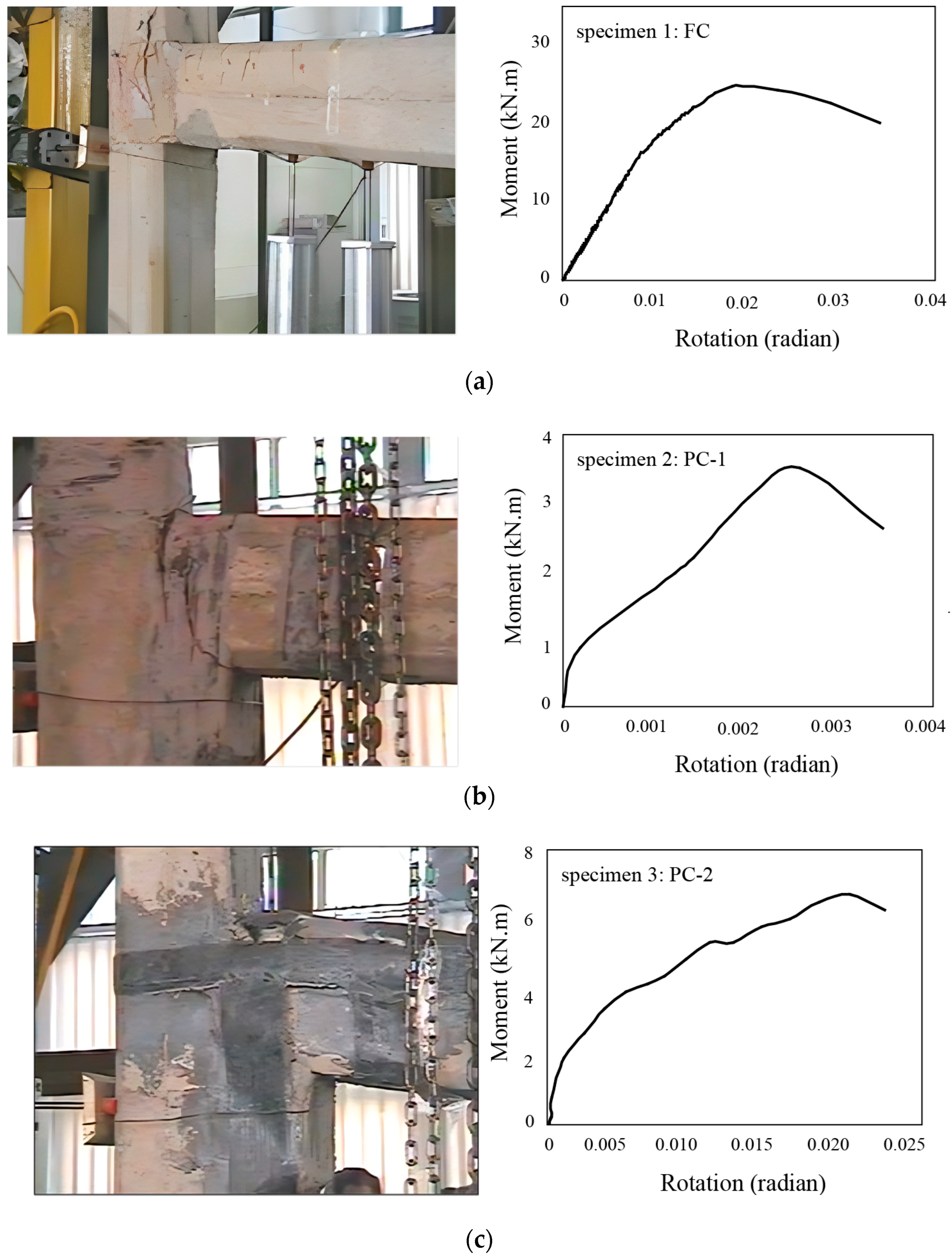
3. Experimental Results

Figure 5a indicates the deformed shape and moment–rotation capacity curve of the initial specimen (Specimen 1: FC) beyond 0.03 radians. Laboratory tests conducted on the FC archetype revealed that the longitudinal reinforcement of the beam yielded near the bearing, closely matching the anticipated theoretical yield in the cantilever beam with the fixed-base condition. The presence of diagonal microfractures within the panel zone of the connection was observed, stemming from inadequate transverse reinforcement. Furthermore, the tensile reinforcement slid despite compliance with the seismic-resistant design provisions for the longitudinal reinforcement and bond length. The failure observed was brittle, indicating a lack of proper ductility in the connection.
Figure 5b illustrates the failure mechanism of the second specimen (Specimen 2: PC-1) alongside its corresponding moment–rotation curve. The connection’s fracture initiation occurred as the spiral FRP wrapped around the beam and the corbel tore at its ultimate tensile capacity, i.e., εu = 0.0155. Concurrently, 25% of the L-shaped FRP sheets, positioned at the connection’s bottom, also tore. Consequently, the connection experienced a 30% reduction in its ultimate moment capacity, primarily carried by the L-shaped sheets. Therefore, the impact of the top and bottom FRPs on enhancing the flexural reinforcement of the PC-CBCC was found to be insignificant. This lack of significant contribution can be attributed to the high concentration of shear stress in the L-shaped FRP sheets while transferring the beam’s tensile force to the spiral FRPs around the column. The tearing of these L-shaped sheets occurred at the folding point when they reached their maximum tensile strain.
In the case of the third specimen (Specimen 3: PC-2), the debonding of the U-shaped FRP sheet from the column was observed during the initial loading stages, specifically at a lateral force of 4000 N, as depicted in Figure 5c. This separation of the FRP from the concrete surface resulted from concentrated shear stress at the location of the flexural crack initiation and propagation across the width of the column. Consequently, the tearing of the beam and corbel FRP spiral commenced at their connection to the U-shaped sheet upon reaching a loading of 5500 N. The tensile fracture of the FRP spiral sheets, caused by the portion of the moment in the corbel at the connection, transpired at the ultimate FRP capacity of εu = 0.0155, aligning closely with 95% conformity to the equilibrium and compatibility equations. Despite the debonding of the U-shaped sheet occurring at ε = 0.001, the adherence of the FRP spiral sheets to the beam could postpone the connection failure up to εu = 0.002. Consequently, at εu = 0.002, the U-shaped sheet abruptly separated as the connection reached only 1/7 of the ultimate capacity of the FRP. To validate the observed debonding load, the debonding stress of the U-shaped sheet, calculated from equilibrium and compatibility equations, was compared to the modified Holzenkampfer formula [41], Equation (1), resulting in an agreement of up to 98%.
f f , deb = f f , max = c 1 E f f ctm n f t f     ( if   l b l b , max ) ;     f f , deb = f f , max l b l b , max ( 2 - l b l b , max )   ( if   l b < l b , max )   ;   l b , max = E f n f t f c 2 f ctm
where fctm represents the tensile strength of concrete, and Ef denotes the module of elasticity of the fibers. lb, lb,max, tf, and nf refer to the bond length, effective bond length, thickness, and the number of FRP layers, respectively. c1 and c2 are equal to 0.64 and 2, respectively [32].
To prevent the debonding of the layers affixed to the concrete surface during loading, a highly efficient mechanical anchor was applied to secure the U-shaped FRP sheets onto the column. This anchoring mechanism played a crucial role in enhancing the adhesion and preventing separation during the testing of the PC-3 archetype (Specimen 4, Figure 6). This was facilitated by the generation of compressive stress on the sheet’s surface, augmenting the shear–friction resistance of the boundary layer across the column’s width. Unlike the PC-2 sample, where the beam and corbel spiral experienced tearing, the PC-3 sample did not undergo significant tensile force on the beam and corbel spiral. This absence of force was attributed to the U-shaped sheet’s adhesion to the column and its adequate rigidity, allowing for moment transferring. Ultimately, the rupture of the concrete near the U-shaped sheet, the longitudinal reinforcement, and the upper cover of the beam led to the connection’s failure under a 19,500 N load. For a visual representation of the failure mechanism in PC-3 in comparison to the other archetypes, refer to Figure 7.
In this case, the separation of the U-shaped sheet occurred at εu = 0.0053, with 34% of the FRP’s ultimate capacity. The delay in the separation of the U-shaped sheet attached to the column, owing to appropriate mechanical anchorage, extended from εu = 0.001 to beyond εu = 0.0053. This extension corresponds to a range from εu = 0.002 to εu = 0.0053 for the U-shaped sheet affixed to the beam. The observed debonding strain of the U-shaped sheet aligns closely with the ultimate strain suggested by Sharif [42] (εu = 0.005) and Arya and Farmer [43] (εu = 0.006), corresponding to 95% and 84% of their strains, respectively. Additionally, the ultimate strain of the FRP sheet was aligned with up to 72% agreement with the values obtained from ACI 440 [44] for beams.

4. Numerical Modeling and Analysis

4.1. Simulation of the Archetypes

ANSYS software was employed for the three-dimensional modeling and analysis of the reinforced concrete connections, as shown in Figure 8a. The ANSYS model for beam–column specimens employed the following four elements: Solid65, Link8, Pipe16, and Solid46.
Concrete materials were simulated using Octahedral elements, specifically Solid65 elements. The Solid65 element was utilized for modeling reinforced concrete material. This element comprises eight nodes with three degrees of freedom each. It possesses the capability to crack in tension and crush under pressure, accommodating both reinforced and unreinforced scenarios. The element allows for the inclusion of three different types of reinforcement and can experience cracking in three mutually perpendicular directions, along with crushing, plastic deformation, and creep. While the reinforcements within this element can induce tension and pressure, they cannot resist cutting forces. Additionally, these reinforcements can undergo plastic shape changes and exhibit creep behavior. This element implemented the Wiliam–Warnke five-parameter failure criterion considering compression failure and tension cracking. To prevent concrete failure modes in compression and tension, significantly impacting connection strength, the following assumptions were made: A 25% of shear resistance was assumed for concrete cracks opening under tension, with 99% of the shear capacity for closed cracks occurring in concrete under compression.
The Link8 element (3-D Spar) has been utilized to model the finite elements of longitudinal beam and column reinforcements. It is assumed to exhibit elastic behavior, and similarity in steel behavior between tension and compression is also assumed. The Poisson’s ratio for steel is set at 0.3, and its modulus of elasticity is considered as Es = 210,000 MPa. This two-point element is defined with a cross-section and initial strain, offering versatility for various applications such as truss elements, springs, and complete interfaces. It operates in three dimensions; the uniaxial element is compressive–tensile, featuring three degrees of freedom in the x, y, and z directions at each node. As it is employed as a joint connection, the Link8 element does not accept any bending. The properties of plasticity, creep, and shrinkage can be defined for the element. Additionally, the transverse reinforcements are modeled using the Solid65 element.
Another crucial consideration is the need to account for the displacement of all nodes, including the middle nodes of the beam. Equations for the displacement dependence, not just rotation, should be formulated. This precaution is essential to prevent convergence issues, particularly when a crack reaches these points. The simultaneous change in many applied locations led to convergence problems, with the middle nodes being particularly susceptible to this issue. To address this matter, virtual elements were modeled due to the constraints of the Solid65 and Link8 elements with three degrees of freedom along the main axes. For this purpose, the Pipe16 element was introduced with very small dimensions and a material of very low strength to ensure a negligible impact on the analysis. This approach allowed the rotation requirement to be satisfied without significantly affecting the overall analysis. Furthermore, considering previous investigations and the observed negligible effects of the reinforcement sliding in the connection, identical deformation was considered for both the concrete and steel bars. However, the opening in the precast connection filled with both grout and adhesive was integrated and modeled as a unified entity.
The FRP sheets were simulated by the Solid46 element with eight-node volume elements and three degrees of freedom per node (movement in the x, y, and z directions). This element can accommodate up to 100 layers, each differing in material, thickness, and fiber placement angle. The material properties assigned to this element are orthotropic, implying distinct values for the modulus of elasticity, Poisson’s ratio, and shear modulus in different directions (planes). When allocating material, the x-axis introduced in the material properties is considered the default local x-axis of the element. A critical consideration was considered for the connection between FRP and concrete. The Solid46 elements should be configured to share common nodes at the interface between FRP and the concrete components. Therefore, instead of generating identical volumes of FRP sheets and then meshing them, the process involves initially creating surrounding nodes for the intended elements based on their dimensions. However, s consistent meshing configuration was applied to all the archetypes, regardless of whether they had pinned or fixed connections. Subsequently, by following a specific order in the selection of the eight element nodes (aligning the local x coordinates with the fiber direction), the desired element is formed using the Create Element function. The material properties are then input in the desired directions. In the chosen connection model, the number of layers for various sheets is defined as two, six, and eight layers, aligning the local x-axis of the element with the fiber direction. The FRP sheets are composed of carbon, and their material properties are defined as orthotropic. The elasticity model in the fiber direction is Ex = 230,000 MPa, while the elastic moduli in the directions perpendicular to the fibers are Ey = 19,806 MPa and Ez = 19,806 MPa. The Poisson’s ratio is specified, and the shear moduli are defined as follows: Gxy = 12,130 MPa, Gzy = 6848.5 MPa, and Gzx = 6848.5 MPa. Loadings were applied to multiple joints near the ends of the beam and column head to conduct nonlinear analyses. Precise boundary conditions were established within the finite element model to incorporate the interaction of all involved components during loading effectively. Accordingly, the degrees of freedom along the x and z directions were constrained on the upper end of the column, while all three degrees of freedom for displacement at the lower end were restricted.
Figure 8b presents a comparison of the moment–rotation curves between the experimental results obtained from the tested specimens and numerical modeling. These results were utilized to validate the computational modeling. As depicted, the simulation of both the pinned and fixed archetypes successfully captured the initial stiffness and ultimate strength of the archetypes. The difference in the ultimate moment corresponding to the initiation of the failure of the experimental samples and the simulated models was negligible, measuring less than 4% and 7% for FC and PC-3, respectively. This discrepancy can be attributed to the tolerance in the expected ultimate tensile strength of the simulated and real materials. However, the model cannot accurately capture the degradation of the stiffness and strength of the joints. This limitation arises from the assumption made in the computational model to avoid converging problems, particularly after severe nonlinearity occurs at the interface of the column and beam. Therefore, future assessment is required to fully capture the behavior of the archetypes, particularly when considerable fractures and debonding occur in the FRP sheets. Once the accuracy of these basic models was confirmed, subsequent archetypes, in addition to the ones tested in the laboratory, were modeled and analyzed using the software. Various parameters were measured during the analysis and comparison among different archetypes, including the rotation–moment curve, stress in concrete at specific steps, strain in tensile longitudinal reinforcements and FRP sheets, crack distribution, ultimate capacity, etc. (Figure 8c).

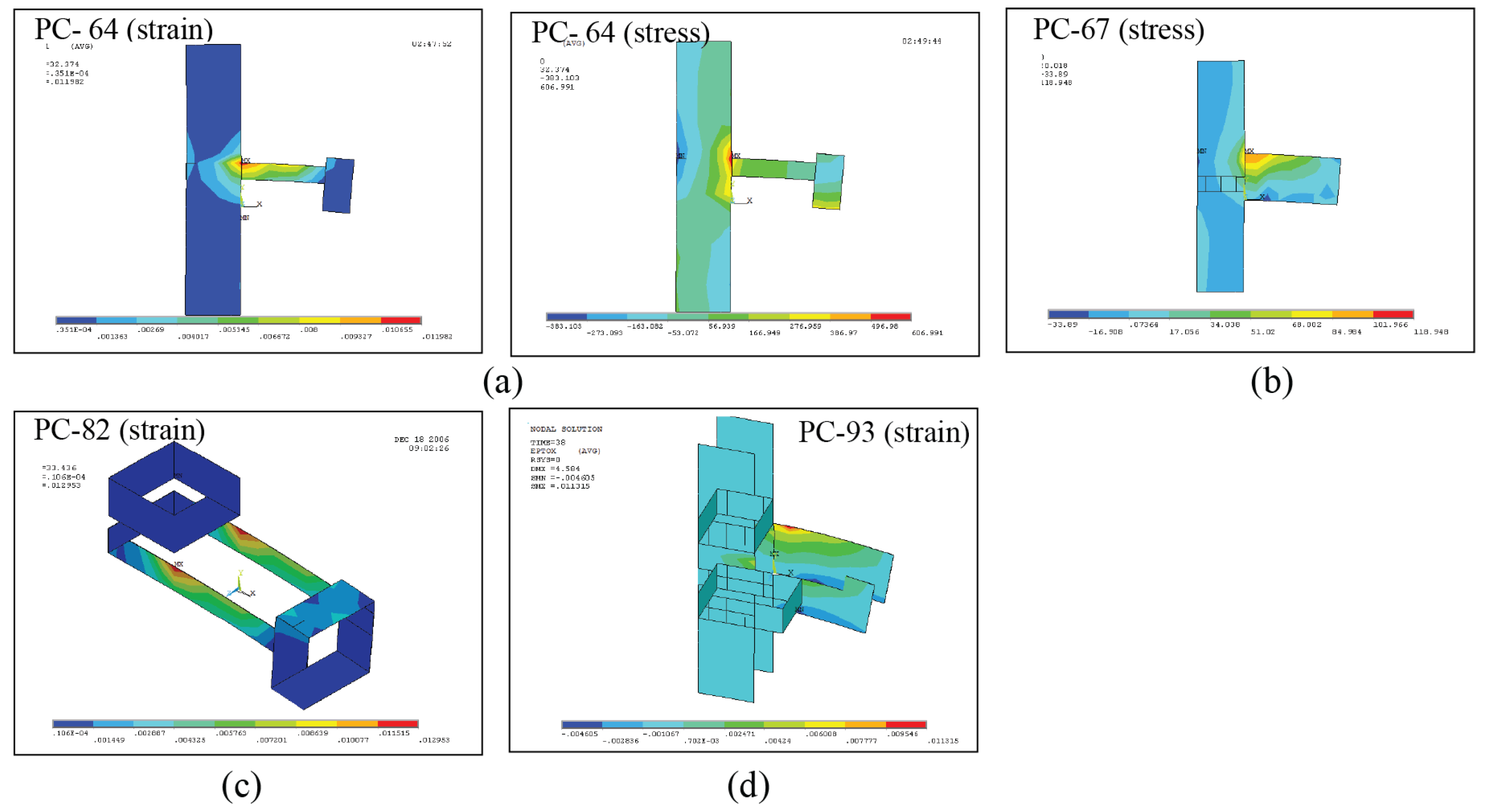
4.2. Analysis of the Illustrative Examples

Based on failure theory and the experimental findings, the most effective solution for flexural reinforcement is utilizing U-shaped FRP sheets. Therefore, a set of precast connections, resembling the PC-3 configuration, were modeled employing U-shaped sheets with varying lengths and widths. These archetypes were denoted as PC-4 to PC-93, as listed in Table 3, consisting of eight layers of U-shaped FRP sheets, arranged, and fastened around both the beam and column. As shown in Figure 9a, three bond lengths (Lx) were considered: (1) 400 mm, covering the entire connection length; (2) 300 mm, similar to the PC-3 specimen; and (3) 200 mm, representing half of the connection length in the beam (the maximum required bond length for the sheet). Furthermore, to evaluate the influence of the U-shaped sheet’s width (Wx) on the connection’s capacity, the effects of three widths, including 50 mm, 130 mm, and 200 mm, were examined. Given that the entire width of the U-shaped sheet was under tension, a width of 50 mm (above the neutral axis), matching the laboratory specimen, was chosen to maximize its tensile capacity. With a width of 130 mm, the FRP reinforcement was extended below the neutral axis to accommodate positive moments induced by actual reciprocal earthquake loading. To cover the entire width of the beam, a width of 200 mm was selected. This decision was based on the absence of chamfers at the corner of the beam, allowing for the entire beam width to be utilized for reinforcement.
Across the PC-4 to PC-12 archetypes (Figure 9b,c), wider U-shaped sheets resulted in reduced tensile stress and strain. Tearing did not occur in any sample. In these samples, the widening of the U-shaped sheets resulted in reduced tensile stress and strain, with no tearing observed. For instance, in the PC-4 connection, the FRP strain reached approximately 60% of its ultimate strain at 0.0091 during the yield tensile of the beam rebars. Additionally, increasing the sheet width from 50 mm in PC-4 to 130 mm in PC-5 and 200 mm in PC-6 enhanced the moment capacity corresponding to the yield stress of the rebars from 25 kN.m to 25.65 kN.m and 28.5 kN.m, respectively. Therefore, widening the FRP sheets covered the neutral axis of the cross-section of the beam and enhanced the moment strength of the connection by increasing their contribution to both the concrete’s compressive capacity and the beam’s tensile rebar.
Connections PC-13 to PC-21 were similar to the PC-4 to PC-12 archetypes in geometry and U-shaped sheet reinforcement. However, two layers were surrounded at the U-shaped sheet’s end (Figure 10a). This full-wrap FRP was added to potentially improve the crack development and stress distribution. The results revealed a 10% strain reduction in the U-shaped sheet due to the full-warp sheets. For instance, PC-19 exhibited approximately 10% less strain under the same loading in its U-shaped sheet than PC-10 (Figure 10a). As the U-shaped sheet width increased, the effectiveness of the added FRPs in reducing strain and stress weakened. This effect became less prominent in the wider sheets, such as PC-15, PC-18, and PC-21, where the width reached 200 mm. The increased U-shaped sheet width resulted in reduced shear stress transmission by the full-wrap sheets, as illustrated in Figure 10a. For cases with 200 mm wide U-shaped sheets, such as PC-21 and PC-12, which exhibited similar strains of 0.0104, there was minimal strain reduction. Moreover, wider U-shaped sheets displayed lower tensile stress in the end spiral. At the same load, PC-21 with a 200 mm wide U-shaped sheet experienced a 49% reduction in tensile stress compared to PC-19 with a 50 mm wide U-shaped sheet, decreasing from 271.33 MPa to 138.69 MPa. This reduction in the effect of the end wrap in shear stress transfer is responsible for the decline, as most shear stress is transferred by the U-shaped sheet surface rather than the full wrap. Additionally, the analysis results from PC-13 to PC-21 indicated that these sheets could not significantly delay or increase the load transfer of the tensile reinforcement, affect the final anchor amount, or diminish crack propagation on the reinforcement’s side. The curves obtained from these archetypes closely resembled those without the end full-wrap sheet.
Connections PC-22 to PC-30 mirrored connections PC-13 to PC-21 but included additional side sheets to reinforce the U-shaped sheet (as depicted in Figure 10b). These side sheets are typically incorporated at the beam’s end of the U-shaped sheet to prevent FRP separation and the crack’s propagation. However, the analysis results of these connections revealed that the side sheets did not reduce the tensile stress in the U-shaped sheet (Table 3). Instead, they caused an increase in tensile stress in the beam’s side plates compared to the full spiral configuration. For instance, the tensile stress in the side sheets of PC-28 was 30% higher than PC-19 (Figure 10a). This heightened stress concentration at the end of the beam’s side sheets led to FRP debonding, which requires proper mechanical restraint to prevent. Moreover, with the increased U-shaped sheet width, the tensile stress in the side sheets decreased. At the same load, the side sheet’s tensile stress in sample PC-30 with a 200 mm wide U-shaped sheet showed a 68% reduction compared to sample PC-28 with a 50 mm wide U-shaped sheet (Figure 10b). This reduction resulted from the diminished effectiveness of the side sheets in shear stress distribution. The analysis results further demonstrated that the side sheets did not impact increasing or delaying the yield load of the tensile reinforcement, enhancing the final anchor, or reducing crack propagation on the reinforcement’s yield side. The behavior of these samples closely matched those without side sheets at the end of the U-shaped sheet.
The two layers of U-shaped sheets were positioned below the beam of the PC-31 to PC-39 connections (Figure 10b). However, analysis revealed that these sheets did not reduce the tensile stress in the U-shaped sheet compared to the samples with a full wrap at the end (Table 3). The main difference was the heightened tensile stress in the final U-shaped sheet compared to the full spiral state. For instance, the tensile stress in the side plates of sample PC-36 was 30% higher than that of PC-19. Similarly, widening the U-shaped sheet led to decreased tensile stress in the final U-shaped sheet. The tensile stress of the sheet adjacent to the beam in sample PC-39 with a 200 mm wide U-shaped sheet showed a 53% reduction compared to sample PC-36 with a 50 mm wide U-shaped sheet.
An analysis of connections PC-40 to PC-57 was developed to assess the impact of wrapping the beam and corbel with U-shaped and side sheets. Notably, the strain in the U-shaped sheets of PC-46 and PC-55 was reduced to 0.0092 and 0.0115 compared to PC-10 with 0.013, marking a 44% and 12% reduction, respectively (Figure 10c). However, widening the U-shaped sheet decreased the effectiveness of the beam and corbel’s FRPs in reducing tensile stress. For example, the tensile stress of the side sheets in PC-57 with a 200 mm U-shaped sheet reached 352.27 MPa, while the stress was 1427.00 MPa for PC-55 with a 50 mm wide U-shaped sheet. Furthermore, the analysis demonstrated that the surrounded beam and corbel with FRPs did not significantly increase the ultimate capacity, delay the yielding load of tensile reinforcement, or reduce the crack propagation. The curves obtained from these archetypes closely resembled those without beam and corbel wrapping (Table 3), albeit with slightly increased connection stiffness. For instance, Figure 10c compares the moment–rotation curves of the PC-46 and PC-55 connections with those of PC-10.
As illustrated in Figure 11, the PC-58 to PC-66 connections were simulated to incorporate the effects of the two layers 1000 mm in length on both sides of the column. Meanwhile, PC-67 to PC-75 employed dual corbel spirals to reinforce the corbel’s bending, and PC-76 to PC-84 featured a full-wrap beam and column with two layers at specific locations. Lastly, through the PC-85 to PC-93 archetypes, the interaction effect of the corbel and column FRP wraps was investigated along with side longitudinal sheets, employing U-shaped sheets with varied dimensions. The analysis results revealed that the employed side sheets to the column did not alter the tensile stress within the U-shaped sheet. For instance, in comparison to PC-19, the strain within the U-shaped sheet for PC-73, PC-82, and PC-93 were 0.0131, 0.0129, and 0.0113, respectively, with corresponding tensile stresses of 0.0117 (10% increase), 0.0117 (10% increase), and 0.0104 (8% increase). Additionally, wrapping the column did not influence the bending behavior of the connection, serving as a reinforcement only in specific cases of structural vulnerability. Moreover, to prevent the buckling of the FRP wrap of the corbel, it is advisable to employ any suitable external restraint.
To explore the influence of the longitudinal reinforcement ratio (ρ), as well as the type of layers of FRPs and concrete strength, three additional samples were examined. The results indicated that increased ρ in the beam amplified the connection capacity, whereas reduced reinforcement lessened their strengths. Notably, the initial and secondary branches of the moment–rotation curve remained unaltered. For instance, PC-4 was analyzed with equivalent beam reinforcement, and its moment–rotation curve is plotted in Figure 12a. Elevated concrete strength (Figure 12b) augmented the connection stiffness across the initial and secondary stiffness of the push curve, albeit without substantial capacity increments. This rise in concrete strength effectively bolstered the shear strength, delaying microcracks and debonding. Moreover, increased stiffness in the FRP fibers (Figure 12c) corresponded to stiffer connections, while reduced fiber stiffness resulted in decreased stiffness. None of the samples exceeded the ultimate sheet strain at load, avoiding any tearing. Hence, reducing the number of layers was feasible in all the archetypes, as long as separation or sheet buckling did not occur until the ultimate strain. Furthermore, thinning the sheet lessened stress linearly concerning the resistant cross-sectional area (i.e., sheet thickness, as the width remains constant).

5. Conclusions

This paper delves into experimental and numerical investigations concerning Precast Concrete Corbel Beam–Column Connections strengthened by FRP sheets and mechanical anchorage plates. Comparative analyses are made between these connections and in situ concrete fixed joints. The findings and key outcomes of this research are as follows:
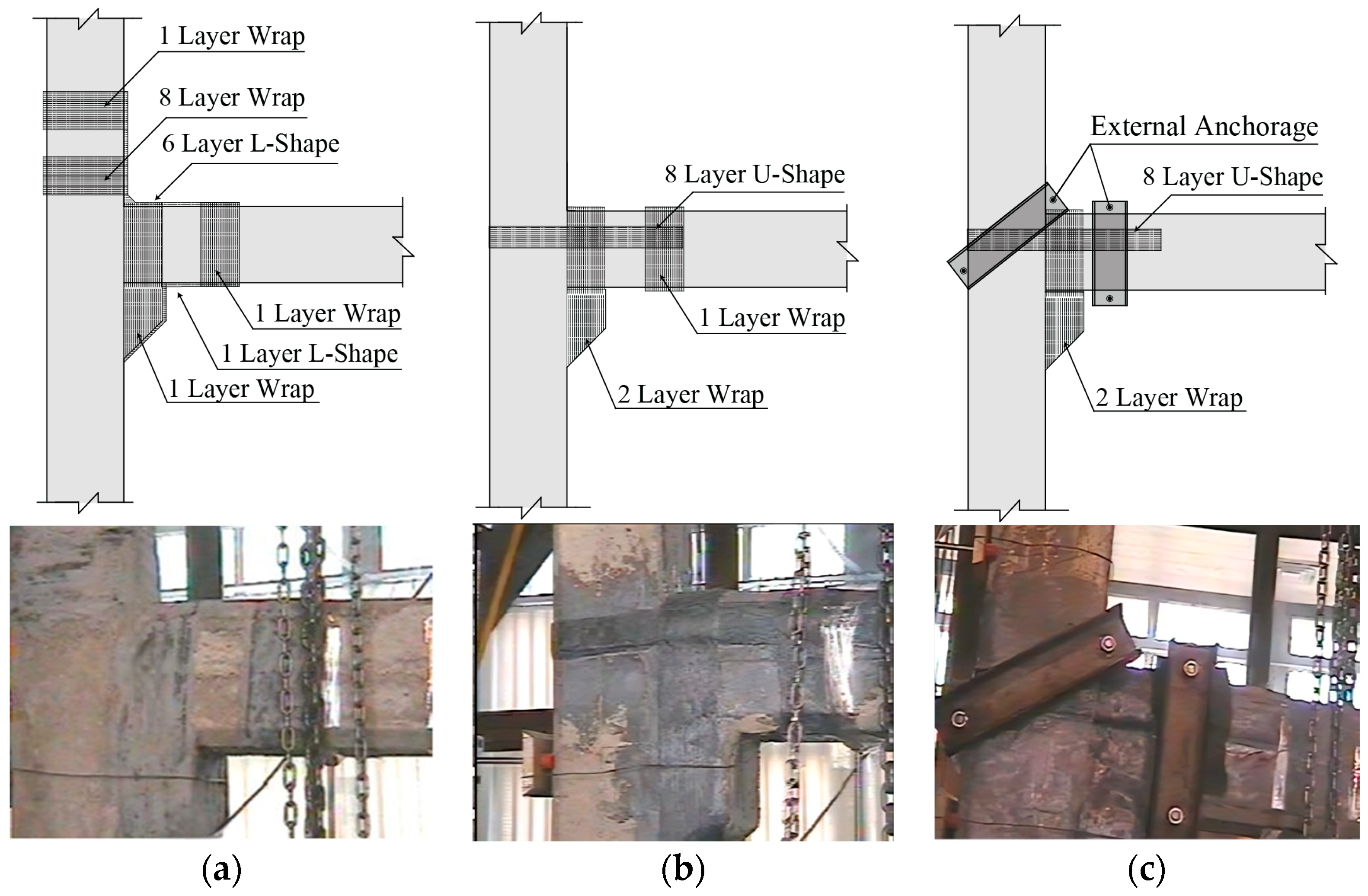
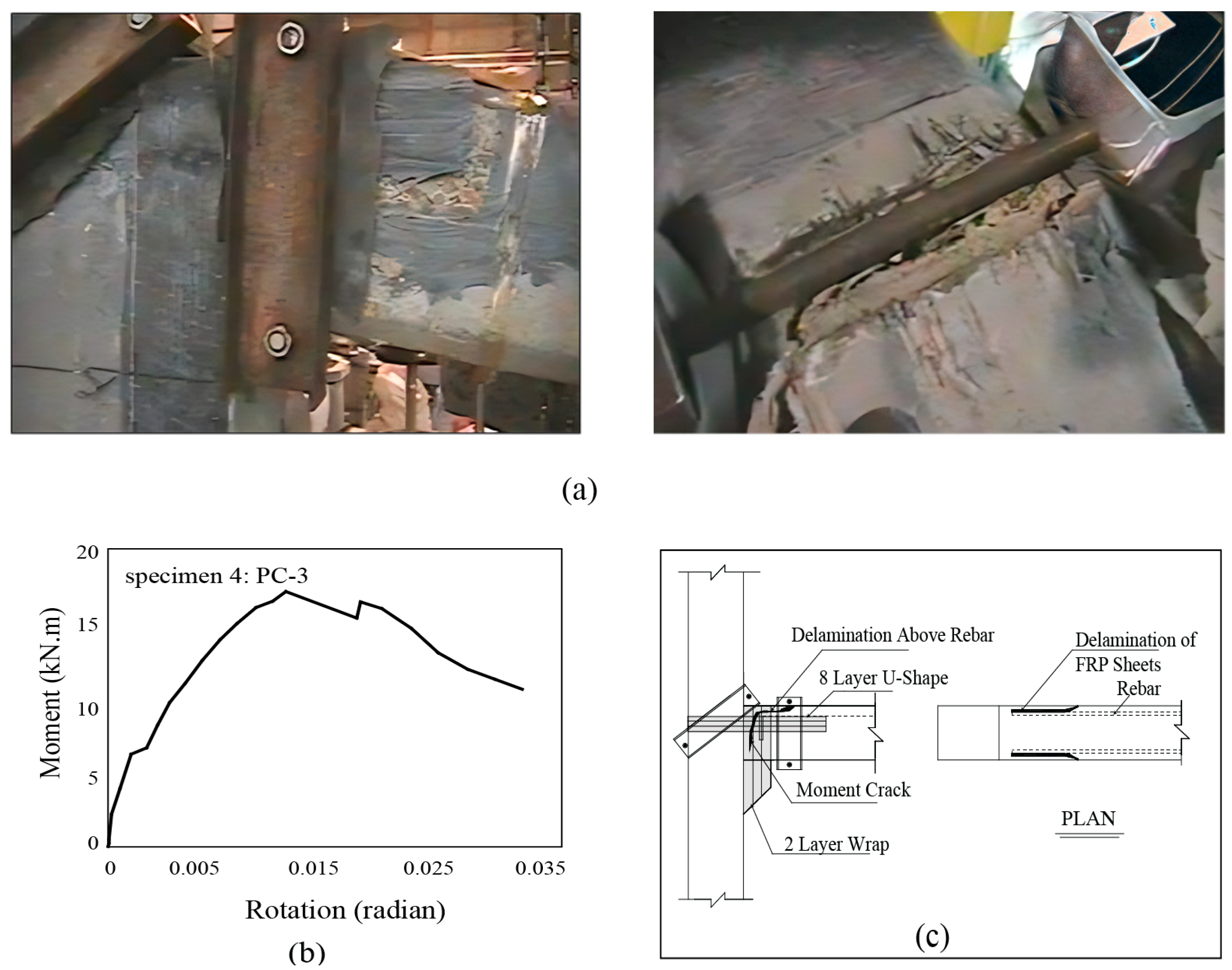
  • Strengthening the PC-1 specimen’s connection with L-shaped FRP sheets at the top and bottom minimally impacted the flexural capacity due to the high shear–stress concentration. Relying solely on the spiral U-shaped FRP sheets without a mechanical anchorage for reinforcing the PC-2 connection did not significantly improve the bending capacity due to the occurring debonding. However, incorporating spiral sheets in PC-2 enhanced the debonding capacity of the fibers by up to 100%, extending the ultimate strain from εu = 0.001 to εu = 0.002. The PC-3 connection increased the moment capacity to 81% of a fixed connection’s flexural capacity, effectively controlling debonding with an anchoring system. Mechanical anchors notably amplified the ultimate separation capacity of the FRP sheets by 530%, increasing the ultimate separation strain from 0.001 to over 0.0053, accounting for 34% of the ultimate tensile strain of the FRPs.
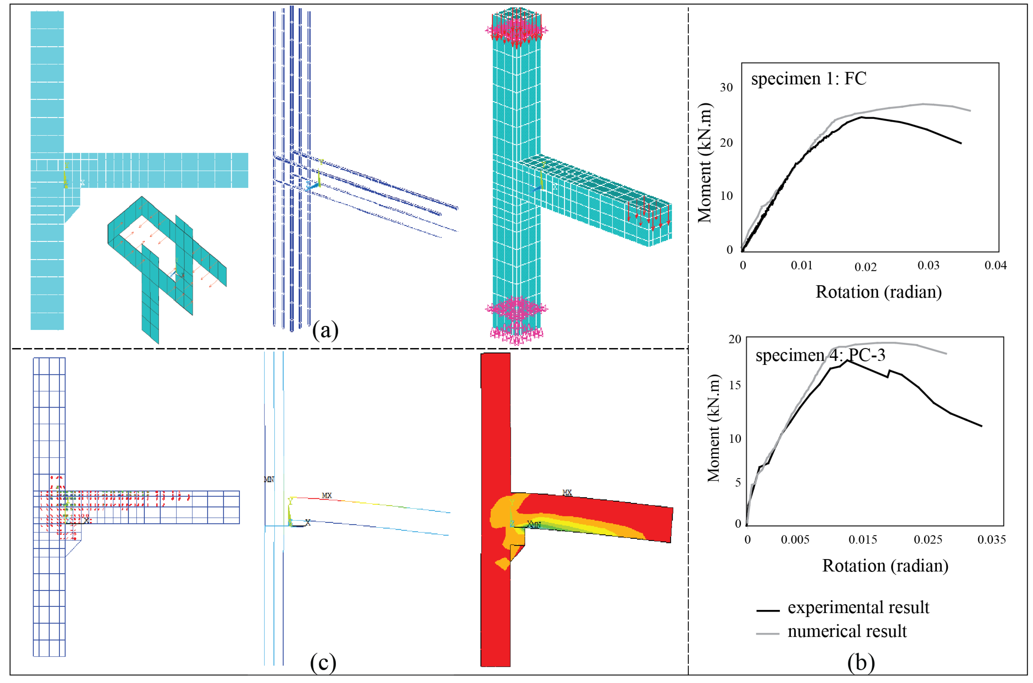
  • The number and thickness of the FRP layers affect the ultimate debonding strain. Mechanical anchors over U-shaped FRP sheets delayed reinforcement yielding. Theoretical analysis for the PC-3 archetype, based on the experimental findings, revealed 35% mobilization of the FRP’s ultimate capacity, with simulation results showing a 41% contribution, indicating a 6% difference between the numerical modeling and theoretical outcomes. The ultimate strain from simulating PC-3 corresponds to an 86% agreement with the ACI-440 strain for simple beams. Additionally, U-shaped FRP sheets can potentially transform a pinned connection into a fully fixed one, significantly enhancing the flexural strength, surpassing that of the cast-in-place FC specimen by approximately 1.19 to 1.5 times.
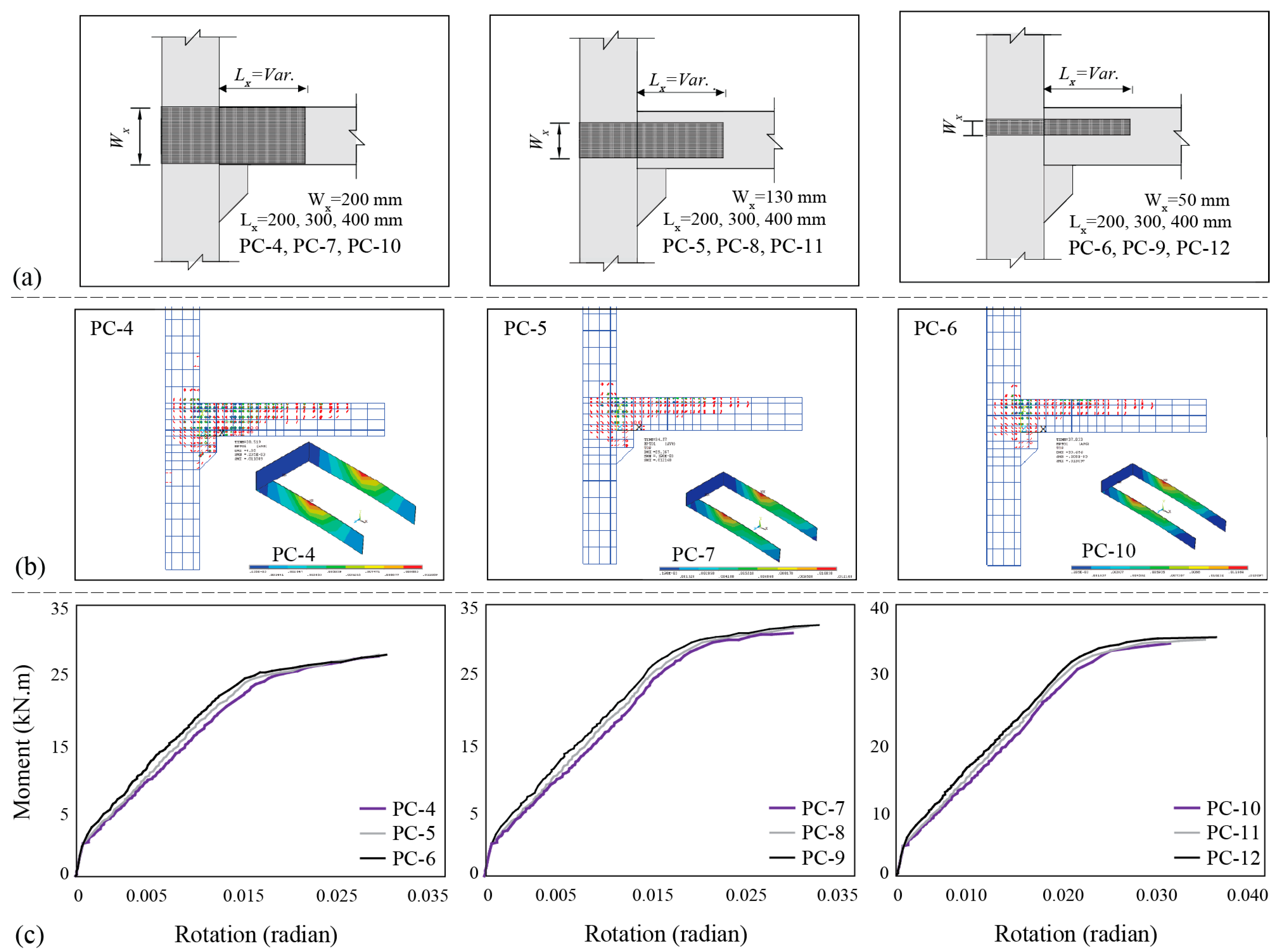
  • The ultimate moment capacity of the connection is enhanced by increasing the bond length of the U-shaped sheet. Similarly, expanding the width of the U-shaped sheet augments the resisting moment of the connection to a certain degree, resulting in an increased bearing capacity of the connection. Additionally, in neither of the archetypes did the FRP sheet strain reach beyond the ultimate strain at the peak load, thereby preventing any tearing. Consequently, there is potential to increase the number of sheet layers across all the samples, if separation or buckling does not occur until the sheet’s ultimate strain.
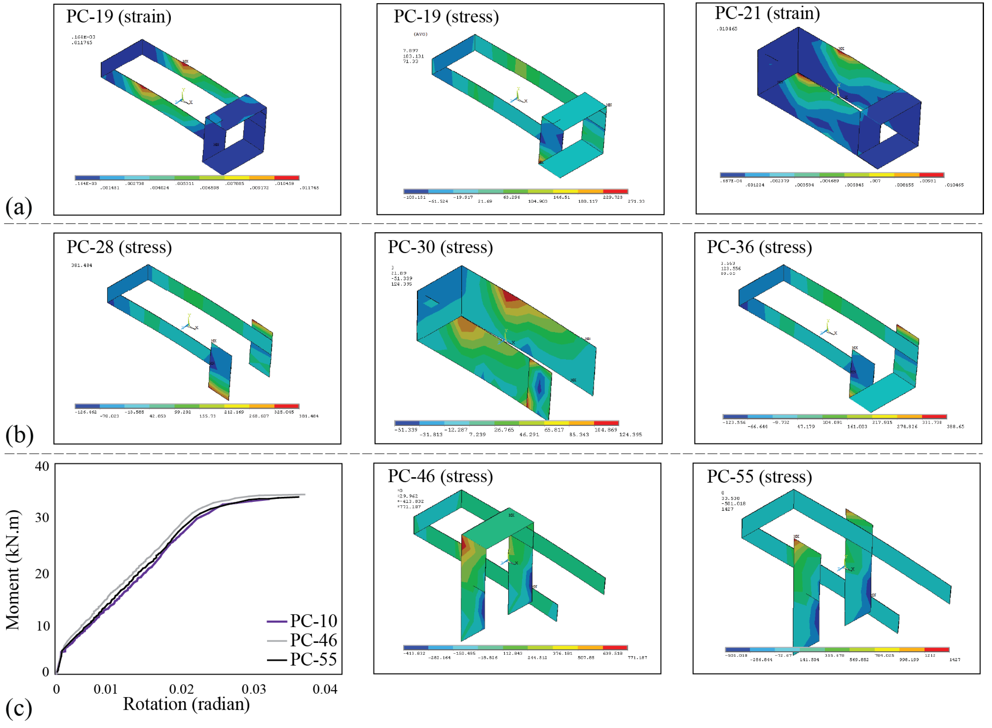
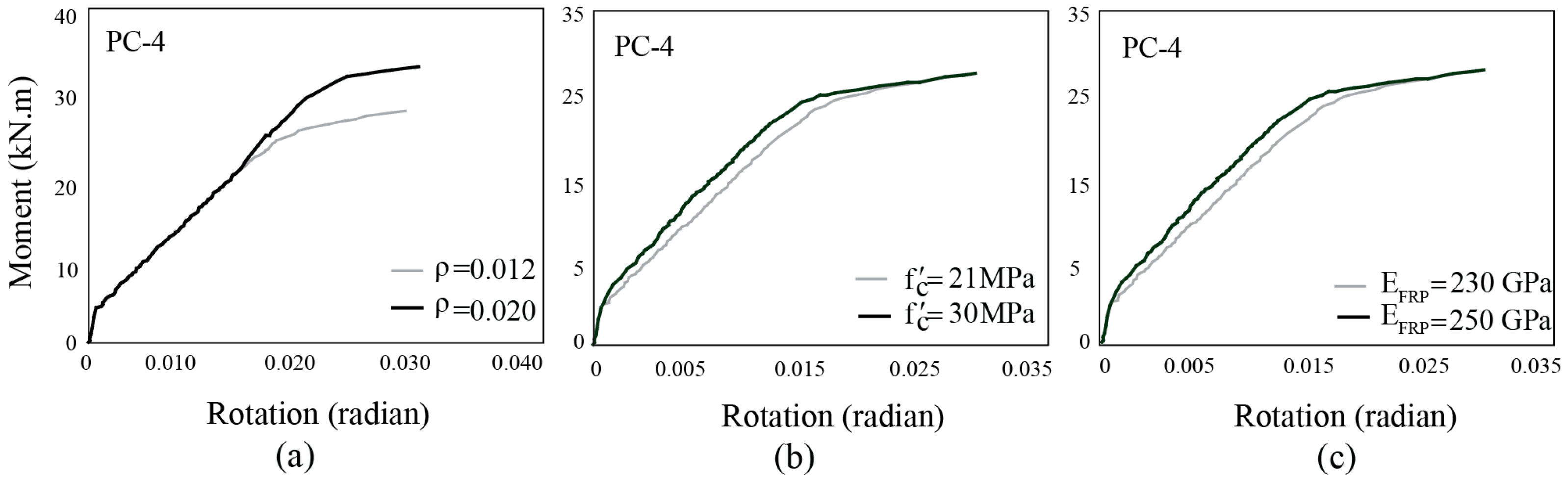
  • Full wrap or side sheets at the end of the U-shaped sheet had minimal impact on the stress reduction or load-bearing capacity. Spirals over the beam and corbel side sheets significantly reduced stress in the U-shaped sheet. However, column-side FRP sheets and full wrap on the column or corbel had a negligible impact on stress reduction or moment resistance. Longitudinal beam reinforcement ratios directly influenced the load-bearing capacity. The concrete strength affected the stiffness more than the rotational moment capacity, while an increased FRP fiber elastic modulus enhanced the connection stiffness.
The study was limited to a few experimental tests focusing on specific reinforcements and FRP sheets under static loads. Further investigation across a broader range of variables is necessary to comprehensively analyze the effectiveness of these reinforcements, particularly those related to anchored U-shaped reinforcement.

Author Contributions

Conceptualization, N.R. (Nima Rahgozar) and N.R. (Navid Rahgozar); methodology, N.R. (Nima Rahgozar) and N.R. (Navid Rahgozar); software, N.R. (Nima Rahgozar) and N.R. (Navid Rahgozar); validation, N.R. (Nima Rahgozar) and N.R. (Navid Rahgozar); formal analysis, N.R. (Nima Rahgozar) and N.R. (Navid Rahgozar); investigation, N.R. (Nima Rahgozar) and N.R. (Navid Rahgozar); writing—original draft preparation, N.R. (Nima Rahgozar) and N.R. (Navid Rahgozar); writing—review and editing, N.R. (Nima Rahgozar) and N.R. (Navid Rahgozar); visualization, N.R. (Nima Rahgozar) and N.R. (Navid Rahgozar); supervision, N.R. (Nima Rahgozar) and N.R. (Navid Rahgozar). All authors have read and agreed to the published version of the manuscript.

Funding

This research received no external funding.

Data Availability Statement

The raw data supporting the conclusions of this article will be made available by the authors on request.

Conflicts of Interest

Author Nima Rahgozar was employed by the company AlphaPlex Consulting Ltd. The remaining authors declare that the research was conducted in the absence of any commercial or financial relationships that could be construed as a potential conflict of interest.

References

  1. Neuberger, Y.M.; de Lima Araújo, D. An improved analytical model for two-step corbels in a precast concrete system. Eng. Struct. 2023, 284, 115947. [Google Scholar] [CrossRef]
  2. Ghayeb, H.H.; Razak, H.A.; Sulong, N.R. Performance of dowel beam-to-column connections for precast concrete systems under seismic loads: A review. Constr. Build. Mater. 2020, 237, 117582. [Google Scholar] [CrossRef]
  3. Akguzel, U.; Pampanin, S. Assessment and design procedure for the seismic retrofit of reinforced concrete beam-column joints using FRP composite materials. J. Compos. Constr. 2012, 16, 21–34. [Google Scholar] [CrossRef]
  4. Huang, C.; Song, J.; Zhang, N.; Lee, G.C. Seismic performance of precast prestressed concrete bridge girders using field-cast ultrahigh-performance concrete connections. J. Bridge Eng. 2019, 24, 04019046. [Google Scholar] [CrossRef]
  5. Sritharan, S.; Aaleti, S.; Henry, R.S.; Liu, K.Y.; Tsai, K.C. Precast concrete wall with end columns (PreWEC) for earthquake resistant design. Earthq. Eng. Struct. Dyn. 2015, 44, 2075–2092. [Google Scholar] [CrossRef]
  6. Singhal, S.; Chourasia, A.; Chellappa, S.; Parashar, J. Precast reinforced concrete shear walls: State of the art review. Struct. Concr. 2019, 20, 886–898. [Google Scholar] [CrossRef]
  7. Abaev, Z.; Valiev, A.; Kodzaev, M. Modeling of the precast concrete hollow-core floor diaphragm with tie beams under seismic action. In AIP Conference Proceedings; AIP Publishing: New York, NY, USA, 2023; Volume 2833. [Google Scholar]
  8. Kurama, Y.C.; Sritharan, S.; Fleischman, R.B.; Restrepo, J.I.; Henry, R.S.; Cleland, N.M.; Ghosh, S.K.; Bonelli, P. Seismic-resistant precast concrete structures: State of the art. J. Struct. Eng. 2018, 144, 03118001. [Google Scholar] [CrossRef]
  9. Del Vecchio, C.; Di Ludovico, M.; Balsamo, A.; Prota, A.; Manfredi, G.; Dolce, M. Experimental investigation of exterior RC beam-column joints retrofitted with FRP systems. J. Compos. Constr. 2014, 18, 04014002. [Google Scholar] [CrossRef]
  10. Aninthaneni, P.K.; Dhakal, R.P.; Marshall, J.; Bothara, J. Experimental investigation of “dry” jointed precast concrete frame sub-assemblies with steel angle and tube connections. Bull. Earthq. Eng. 2020, 18, 3659–3681. [Google Scholar] [CrossRef]
  11. Li, H.; Chen, W.; Hao, H. Dynamic response of precast concrete beam with wet connection subjected to impact loads. Eng. Struct. 2019, 191, 247–263. [Google Scholar] [CrossRef]
  12. Martins, R.; Carmo, R.D.; Costa, H.; Júlio, E. A review on precast structural concrete walls and connections. Adv. Struct. Eng. 2023, 26, 2600–2620. [Google Scholar] [CrossRef]
  13. Zhang, J.; Ding, C.; Rong, X.; Yang, H.; Wang, K.; Zhang, B. Experimental seismic study of precast hybrid SFC/RC beam–column connections with different connection details. Eng. Struct. 2020, 208, 110295. [Google Scholar] [CrossRef]
  14. Psycharis, I.N.; Mouzakis, H.P. Shear resistance of pinned connections of precast members to monotonic and cyclic loading. Eng. Struct. 2012, 41, 413–427. [Google Scholar] [CrossRef]
  15. Holly, I.; Abrahoim, I. Connections and joints in precast concrete structures. Slovak J. Civ. Eng. 2020, 28, 49–56. [Google Scholar] [CrossRef]
  16. Iverson, J.K.; Hawkins, N.M. Performance of Precast/Prestressed Concrete Building Structures During the Northridge Earthquake. PCI J. 1994, 39, 65–76. [Google Scholar] [CrossRef]
  17. Wu, G.; Feng, D.C.; Wang, C.L. Ductile Precast Concrete Frame with Dry-Connections. In Novel Precast Concrete Structure Systems; Springer Nature: Singapore, 2023; pp. 33–86. [Google Scholar]
  18. Xie, L.; Wu, J.; Zhang, J.; Liu, C. Experimental study on mechanical behaviour of replaceable energy dissipation connectors for precast concrete frames. Structures 2021, 33, 3147–3162. [Google Scholar] [CrossRef]
  19. Mostofinejad, D.; Arefian, B. Generic assessment of effective bond length of FRP-concrete joint based on the initiation of debonding: Experimental and analytical investigation. Compos. Struct. 2021, 277, 114625. [Google Scholar] [CrossRef]
  20. Aninthaneni, P.K.; Dhakal, R.P.; Marshall, J.; Bothara, J. Nonlinear cyclic behaviour of precast concrete frame sub-assemblies with “dry” end plate connection. Structures 2018, 14, 124–136. [Google Scholar] [CrossRef]
  21. Li, Z.Y.; Kang, S.B.; He, H.; Lu, W.Q.; Liu, H.J.; Lu, C.J. Seismic behaviour of precast concrete beam-column connections with bolted end plates. Structures 2023, 58, 105343. [Google Scholar] [CrossRef]
  22. Rajeswari, M.; Jaya, K.P. Cyclic performance of emulative precast beam to column connection with corbel using dowel bar. Rev. Constr. 2022, 21, 354–367. [Google Scholar]
  23. Nimse, R.B.; Joshi, D.D.; Patel, P.V. Experimental study on precast beam column connections constructed using RC corbel and steel billet under progressive collapse scenario. In Structures Congress; ASCE: Reston, VA, USA, 2015; pp. 1101–1117. [Google Scholar]
  24. Bahrami, S.; Madhkhan, M.; Shirmohammadi, F.; Nazemi, N. Behavior of two new moment resisting precast beam to column connections subjected to lateral loading. Eng. Struct. 2017, 132, 808–821. [Google Scholar] [CrossRef]
  25. Dasgupta, A. Retrofitting of concrete structure with fiber reinforced polymer. Int. J. 2018, 4, 42–49. [Google Scholar]
  26. Saadatmanesh, H.; Ehsani, M. Fiber composite plates can strengthen beams. Concr. Int. 1997, 12, 65–76. [Google Scholar]
  27. Xian, G.; Guo, R.; Li, C. Combined effects of sustained bending loading, water immersion and fiber hybrid mode on the mechanical properties of carbon/glass fiber reinforced polymer composite. Compos. Struct. 2022, 281, 115060. [Google Scholar] [CrossRef]
  28. Aljidda, O.; Alnahhal, W.; El Refai, A. Bond Durability of Near-Surface-Mounted BFRP and GFRP Bars in Aggressive Environments. J. Compos. Constr. 2023, 27, 04023055. [Google Scholar] [CrossRef]
  29. Li, J.; Bakoss, S.L.; Samali, B.; Ye, L. Reinforcement of concrete beam–column connections with hybrid FRP sheet. Compos. Struct. 1999, 47, 805–812. [Google Scholar] [CrossRef]
  30. Shrestha, R.; Smith, S.T.; Samali, B. Strengthening RC beam–column connections with FRP strips. Proc. Inst. Civ. Eng. -Struct. Build. 2009, 162, 323–334. [Google Scholar] [CrossRef]
  31. Allam, K.; Mosallam, A.S.; Salama, M.A. Experimental evaluation of seismic performance of interior RC beam-column joints strengthened with FRP composites. Eng. Struct. 2019, 196, 109308. [Google Scholar] [CrossRef]
  32. Antonopoluos, C.P.; Triantafillou, T.C. Analysis of FRP-Strengthened RC Beam-Column Joints. Compos. Constr. 2002, 6, 41–51. [Google Scholar] [CrossRef]
  33. Gergely, I.; Pantelides, C.P.; Reaveley, L.D. Shear Strengthening of RC T-joints Using CFRP Composites. Compos. Constr. 2000, 4, 56–64. [Google Scholar] [CrossRef]
  34. Parvin, A.; Granata, P. External Fiber Composite Reinforcement of Concrete Structural Members. In Adaptive Structures, Eighth Japan/US Conference Proceedings; CRC Press: Boca Raton, FL, USA, 1998; pp. 942–948. [Google Scholar]
  35. Antonopoluos, C.P.; Triantafillou, T.C. Experimental Investigation of FRP-Strengthened RC Beam-Column Joints. Compos. Constr. 2003, 6, 39–49. [Google Scholar] [CrossRef]
  36. Harmon, T.G.; Kim, Y.J.; Johnson, T.; Stark, A. Bond of Surface-Mounted Fiber-Reinforced Polymer Reinforcement for Concrete Structures. ACI Struct. J. 2003, 57, 557–564. [Google Scholar]
  37. Tumialan, G.; Serra, P.; Nanni, A.; Belarbi, A. Concrete Cover Delamination in Reinforced Concrete Beams Strengthened with Carbon Fiber Reinforced Polymer Sheets. In Fiber Reinforced Polymer Reinforcement for Reinforced Concrete Structures, Proceedings of the Fourth International Symposium, SP-188; Dolan, C.W., Rizkalla, S.H., Nanni, A., Eds.; American Concrete Institute: Farmington Hills, MI, USA, 1999; pp. 725–735. [Google Scholar]
  38. ACI Committee. Building Code Requirements for Structural Concrete (ACI 318-08) and Commentary; American Concrete Institute: Farmington Hills, MI, USA, 2008. [Google Scholar]
  39. Mass, G.R. Proportioning mass concrete incorporating Pozzolans using ACI 211.1. Concr. Int. 1982, 4, 48–55. [Google Scholar]
  40. Hernandez, D.A.; Orlandi, M.O. Mechanical properties of composites materials SIKACARBODURS512, SIKADUR 30 and SIKADUR 330. In Proceedings of the 22o CBECiMat–Congresso Brasileiro de Engenharia e Ciência dos Materiais, Natal, RN, Brasil, 6–10 November 2016. [Google Scholar]
  41. Holzenkampfer, O. Ingenieurmodelle des Verbundes Geklebter Bewehrung fur Betonbauteile. Ph.D. Thesis, TU Braunschweig, Braunschweig, Germany, 1994. (In German). [Google Scholar]
  42. Sharif, A.; Al-Sulaimani, G.J.; Basunbul, I.A.; Baluch, M.H.; Ghaleb, B.N. Strengthening of Initially Loaded Reinforced Concrete Beams Using FRP Plates. ACI Struct. J. 1994, 91, 160–168. [Google Scholar]
  43. Arya, C.; Farmer, N. Design guidelines for flexural strengthening of concrete members using FRP composites. In FRPRCS-5: Fibre-Reinforced Plastics for Reinforced Concrete Structures, Proceedings of the Fifth International Conference on Fibre-Reinforced Plastics for Reinforced Concrete Structures, Cambridge, UK, 16–18 July 2001; Thomas Telford Publishing: London, UK, 2001; Volume 1, pp. 167–176. [Google Scholar]
  44. ACI Committee 440. Guide for the design and construction of externally bonded FRP systems for strengthened concrete structures, ACI 440.2R-02. In Structures Congress 2005: Metropolis and Beyond; ASCE: Reston, VA, USA, 2005. [Google Scholar]
Figure 1. Reinforcement details of the test specimens: (a) fixed (FC) and (b) pinned (PC) connections.
Buildings 14 00387 g001
Figure 2. Detailing of the FRP wrap layout for the (a) PC-1, (b) PC-2, and (c) PC-3 specimens.
Buildings 14 00387 g002
Figure 3. Preparation of the test archetypes: (a) reinforcement processing, (b) concrete pouring and molding, and (c) FRP wrapping.
Buildings 14 00387 g003
Figure 4. (a) Dimensions of the test specimens and apparatuses; (b) hydraulic jack and reaction frame; and (c) LVDT, load cell, and digital interface measuring devices.
Buildings 14 00387 g004
Figure 5. (a) Mechanism and moment–rotation capacity curve of the (a) FC, (b) PC-1, and (c) PC-2 specimens.
Buildings 14 00387 g005
Figure 6. PC-3 specimen: (a) FRP debonding at the end of the U-shaped sheet, (b) moment–rotation capacity curve, and (c) failure mechanism.
Buildings 14 00387 g006
Figure 7. Comparison of the moment–rotation capacity curves among the FC, PC-1, PC-2, and PC-3 archetypes.
Buildings 14 00387 g007
Figure 8. Modeling and analysis of the FC and PC archetypes: (a) three-dimensional simulation, (b) schematic of the analysis results, and (c) verification of numerical modeling.
Buildings 14 00387 g008
Figure 9. Specifications of the U-shaped FRP sheet with (a) different dimensions. (b) Distribution of cracks in the connections and stress in the FRPs. (c) Moment rotation curves of the archetypes.
Buildings 14 00387 g009
Figure 10. Effects of a (a) full wrap and (b) 2 and 3 side wraps at the end of the U-shaped sheet and (c) wrapping on the corbel location.
Buildings 14 00387 g010
Figure 11. Effects of confinement of the column along with a wrapping (a) beam with U-shaped FRP, (b) corbel with 2 side sheets, (c) corbel with dual spirals, and (d) full-wrap beam and column.
Buildings 14 00387 g011
Figure 12. Moment–rotation curves of the PC-4 connection considering differences in the (a) reinforcement ratios, (b) concrete strengths, (c) and modulus of elasticity of the FRPs.
Buildings 14 00387 g012
Table 1. Specifications of the concrete and FRP materials for the fixed and pinned connections.
Archetypef′c (MPa)ρfb (%)ρfw (%)
FC21.30.000.00
PC-123.20.250.11
PC-223.10.220.22
PC-321.10.220.22
Table 2. Material properties of the FRP sheets.
TypeE (GPa)W(g/m2)γ (g/m3)Fu (MPa)εu (%)t (mm)
SikaWrap-200C *230200 ± 5%1.8039001.550.11
* Sika Corporation.
Table 3. Dimensions of the U-shaped FRP (Lx and Wx), and the ultimate and normalized moment strength of the connection (Mu) and strain in the FRP.
ArchetypeLx
(mm)
Wx
(mm)
Mu
(kN.mm)
Mu/Mu, FCεu(U-Shap)ε/εu
FC (1)--241.00--
PC-3 (1)3005019.50.81--
PC-4, PC-13, PC-22, PC-312005028.51.190.01110.72
PC-5, PC-14, PC-23, PC-3220013095.21.210.01050.68
PC-6, PC-15, PC-24, PC-33200200 29.2 1.220.00990.64
PC-7, PC-16, PC-25, PC-3430050 31.2 1.300.01220.79
PC-8, PC-17, PC-26, PC-35300130 32.3 1.350.01150.74
PC-9, PC-18, PC-27, PC-36300200 32.5 1.350.01080.7
PC-10, PC-19, PC-28, PC-3740050 34.1 1.420.01310.84
PC-11, PC-20, PC-29, PC-38400130 35.0 1.460.01150.74
PC-12, PC-21, PC-30, PC-39400200 35.4 1.470.01040.67
PC-40 (2)2005029.71.240.00740.48
PC-41 (2)20013029.41.230.00810.52
PC-42 (2)20020029.51.230.00890.57
PC-43 (2)3005032.21.340.00810.52
PC-44 (2)30013032.71.370.00920.59
PC-45(2)30020032.81.370.00970.63
PC-46 (2)4005035.11.460.00870.56
PC-47 (2)40013035.71.490.00920.59
PC-48 (2)40020035.91.500.00930.6
PC-49 (2)2005029.61.230.00870.56
PC-50 (2)20013029.41.230.00880.57
PC-51 (2)20020029.31.220.00880.57
PC-52 (2)300503.210.130.00970.62
PC-53 (2)30013032.71.360.00970.62
PC-54 (2)30020032.71.360.00970.62
PC-55 (2)4005035.00.150.01020.66
PC-56 (2)40013035.61.480.01040.67
PC-57 (2)40020035.81.490.01050.68
PC-58 (3)2005029.31.230.01110.72
PC-59 (3)20013029.81.250.01050.68
PC-60 (3)20020030.11.260.00990.64
PC-61 (3)3005032.11.340.01220.79
PC-62 (3)30013033.31.390.01150.74
PC-63 (3)30020033.41.390.01080.7
PC-64 (3)4005035.11.460.01310.84
PC-65 (3)40013036.01.500.01150.74
PC-66 (3)40020036.41.510.01040.67
PC-67 (2,3), PC-76 (2,3)2005028.21.190.01070.69
PC-68 (2,3), PC-77 (2,3)20013027.51.150.00970.62
PC-69 (2,3), PC-78 (2,3)20020027.41.150.0090.58
PC-70 (2,3), PC-79 (2,3)3005032.11.340.01220.79
PC-71 (2,3), PC-80 (2,3)30013031.31.310.01080.7
PC-72 (2,3), PC-81 (2,3)30020030.91.290.010.64
PC-73 (2,3), PC-82 (2,3)4005034.31.430.01280.82
PC-74 (2,3), PC-83 (2,3)40013036.61.530.01170.75
PC-75 (2,3), PC-84 (2,3)40020037.11.540.01060.68
PC-85 (2,3)2005032.21.360.01220.79
PC-86 (2,3)20013032.61.360.01150.74
PC-87 (2,3)20020032.91.380.01080.7
PC-88 (2,3)3005035.31.470.01340.93
PC-89 (2,3)30013036.51.530.01260.81
PC-90 (2,3)30020036.51.520.01180.76
PC-91 (2,3)4005038.61.610.01440.93
PC-92 (2,3)40013039.41.650.01260.81
PC-93 (2,3)40020039.91.660.01140.74
(1) Experimental models. (2) Connections with FRP-wrapped corbels. (3) Connections with FRP-wrapped columns.
Disclaimer/Publisher’s Note: The statements, opinions and data contained in all publications are solely those of the individual author(s) and contributor(s) and not of MDPI and/or the editor(s). MDPI and/or the editor(s) disclaim responsibility for any injury to people or property resulting from any ideas, methods, instructions or products referred to in the content.

