1. Introduction
The development of the steel–concrete joint (SCJ) marks a significant breakthrough in bridge engineering. The SCJ effectively integrates the high load-bearing capacity of steel with the superior durability of concrete, leading to significant improvements in structural performance [
1,
2]. In recent years, as the SCJ has been widely adopted in practical engineering projects, the technical framework for this connection method has steadily matured, accompanied by substantial growth in accumulated expertise related to design and construction [
3,
4,
5]. Nevertheless, SCJ connection technology continues to evolve, posing numerous unresolved challenges while offering substantial untapped potential.
The SCJ consists of steel structures, concrete, shear studs, and Perfobond Leiste (PBL) shear connectors [
6]. Research on the SCJ primarily employs model experiments, numerical simulations, and theoretical analysis [
7,
8,
9,
10,
11]. Jia et al. [
12] investigated the effects of structural parameter variations on the mechanical performance of the SCJ, revealing that changes in bearing plate thickness significantly influenced the stress distribution at the connection. Cheng et al. [
13] and Zhang et al. [
14] analyzed the load transfer mechanism of the SCJ under axial force, identifying the bearing plate and connectors as critical load-bearing components. He et al. [
15] evaluated the impact of ultra-high-performance concrete (UHPC) on the mechanical behavior of the SCJ, demonstrating that UHPC substantially improved the load-bearing capacity of the joint. Yao et al. [
16] introduced a novel SCJ design featuring front and rear bearing plates with concrete infill, which exhibited superior stress distribution and load transfer performance under loading conditions. Xin et al. [
17] investigated the ultimate load-bearing capacity and buckling modes of stiffened ribs in composite structures. Yang et al. [
18] developed two simplified formulas to evaluate the deformation performance of SCJs. Valente et al. [
19] found that using lightweight concrete instead of normal-density concrete reduces the connection load capacity.
For the connection between steel structures and concrete, Su et al. [
20] analyzed the force mechanism of shear connectors and proposed an empirical expression for the shear strength of these connectors. He et al. [
21] studied the shear capacity of perforated steel plates in steel–concrete connections through push-out tests. Zhao et al. [
22] conducted experimental research on PBL shear connectors embedded deeply in reinforced concrete and proposed a formula to estimate the bearing capacity of PBL shear connectors. He et al. [
23] proposed an analytical model and corresponding formula for the ultimate resistance of PBL connectors under shear failure. Li et al. [
24] and Zou et al. [
25] studied the interaction at the steel–UHPC interface. Ahn et al. [
26] found that the shear capacity of perforated steel plates is directly proportional to the strength of the concrete.
For the load transfer calculation of SCJs, the Chinese code [
27] provides empirical formulas for calculating the load carried by the steel structure and concrete at the bearing plate, as well as a formula for determining the maximum shear force of shear connectors. Zhang et al. [
28], based on elastic deformation theory, derived a formula for calculating the shear force in shear connectors within SCJs. Zhang et al. [
29] considered the slip effect between steel and concrete, as well as the local bearing effect of the bearing plate on concrete, and established a simplified calculation model for SCJs. Zhang et al. [
30] developed a load–slip deformation coordination theoretical model for PBL shear connector groups and proposed a corresponding load–slip deformation coordination calculation method. Wang et al. [
31] proposed a simplified calculation model based on deformation coordination theory to estimate the axial force transfer ratio between the bearing plate and shear connectors in SCJs.
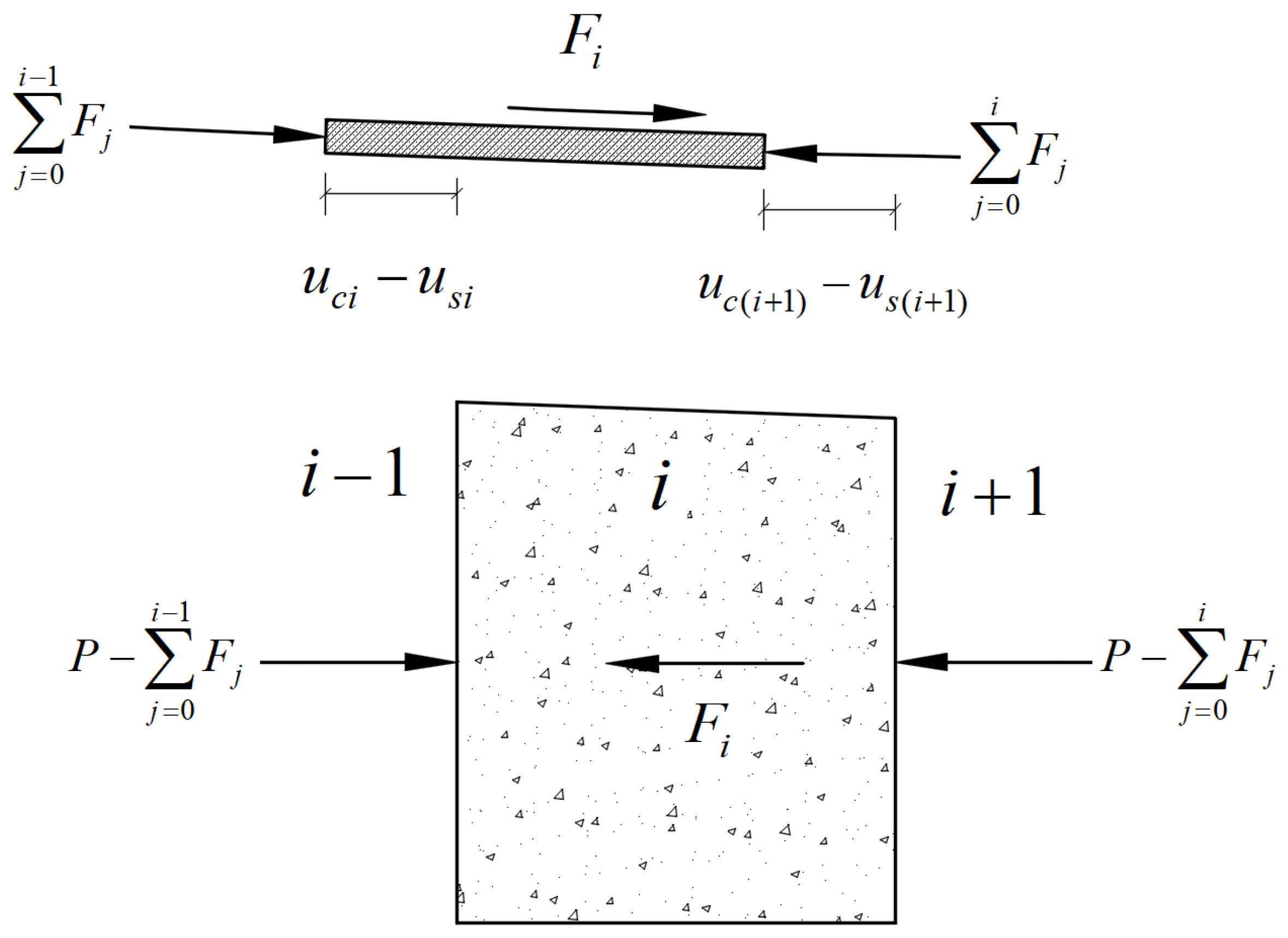
Current theoretical research on SCJs primarily focuses on the load transfer calculation of components such as the bearing plate and shear connectors within the SCJ. However, there is limited research on the direct bearing effects at the ends of steel beams. The large-size PBL-stiffened SCJ, as an innovative structural form, effectively enhances the mechanical performance of SCJs by combining PBL stiffening ribs with the bearing plate. However, the structure of large-size PBL-stiffened SCJs is complex, and the interaction mechanism among the steel beam end, PBL connectors, and bearing plate remains unclear. Therefore, it is necessary to investigate the design principles and simplified calculation model for large-size PBL-stiffened SCJs. To this end, based on the load-bearing characteristics of large-size PBL stiffening ribs, where only the top of the concrete dowel provides the main bearing capacity [
32], the relative slip parameter (∆xi) between steel and concrete in the simplified calculation model proposed by Wang et al. [
31] was modified. A new derivation was obtained, making the derived simplified model suitable for the design calculation of large-size PBL-stiffened SCJs. Additionally, the derived simplified model further considers the constraint effects at the ends of steel beams, allowing for the calculation of the load transfer ratio among the steel beam end, PBL connectors, and bearing plate, clarifying their interaction mechanism. Finally, based on the derived simplified calculation model, the design parameters affecting the mechanical performance of SCJs were analyzed to provide valuable references for the design and calculation of similar structures.
2. Overview of Project
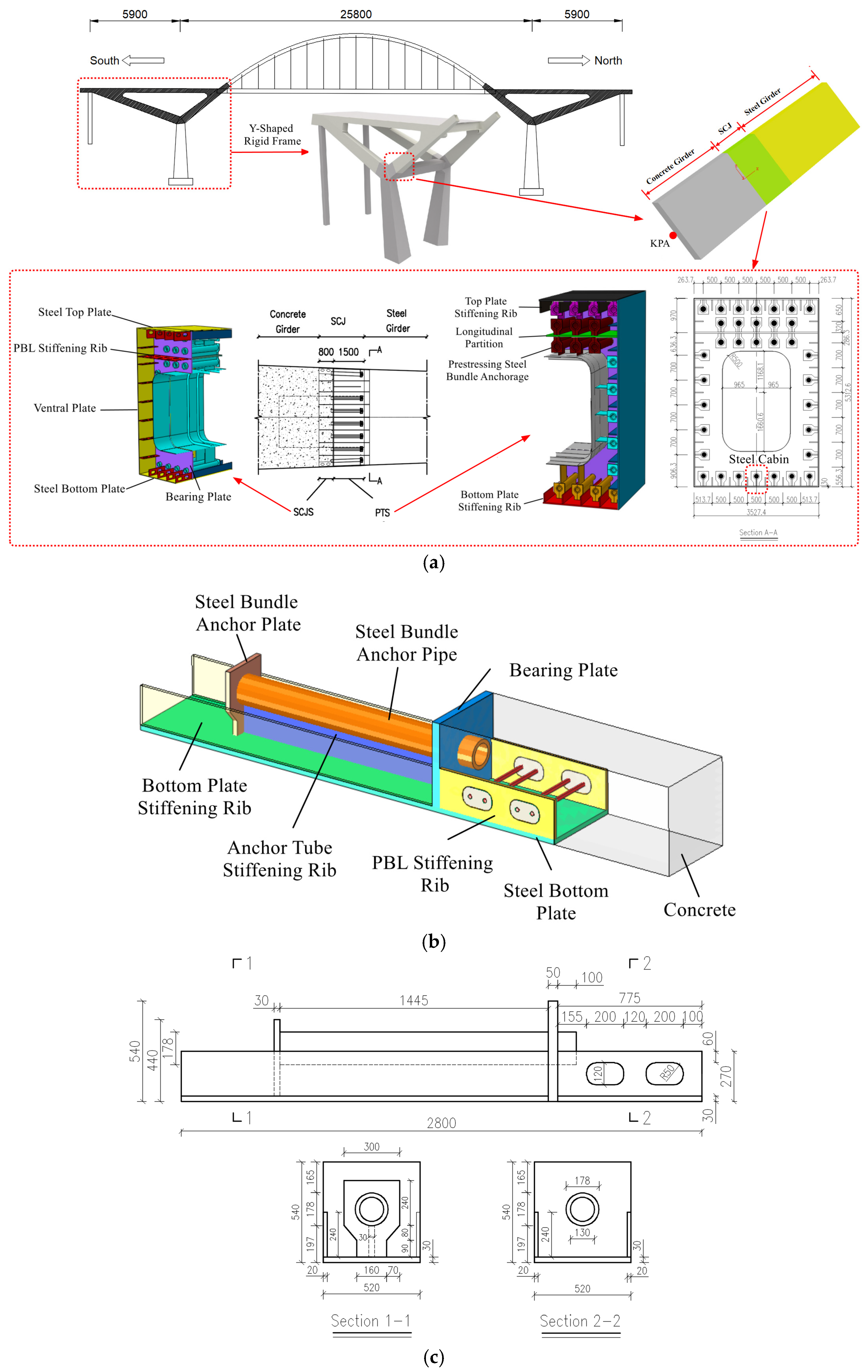
The main span of the bridge is 59 m + 258 m + 59 m, which is composed of a Y-shaped rigid frame and a main arch. The Y-shaped rigid frame is a composite structure, and the main arch structure is a steel box arch. The Y-shaped rigid frame consists of a concrete girder, an SCJ, and a steel girder. The segment from 0 to 7.5 m from the KPA point is the concrete girder composed of C60 steel fiber-reinforced concrete. The segment from 7.5 to 9.8 m from the KPA point is the SCJ. The steel girder adopts a single-box, single-cell steel girder structure. A schematic diagram of the SCJ is shown in
Figure 1a.
The SCJ is designed to withstand compressive forces and transfer shear forces. To ensure the local stability of the steel plates in the SCJ, PBL stiffening ribs are incorporated within the joint. The SCJ is prefabricated and hoisted onto the support structure at the construction site. Prestressing tendons are threaded through the SCJ according to their designated order, followed by rebar binding and concrete pouring. Once the concrete reaches 95% of its design strength and the elastic modulus meets the specified value, the SCJ is prestressed, grouted in the prestressing ducts, and the anchor heads are sealed with concrete.
The entire SCJ consists of two components: the steel–concrete joint section (SCJS) for direct force transfer and the prestressed tensioning section (PTS). The SCJS mainly consists of the top and bottom plates, ventral plates, PBL stiffening ribs, and infilled concrete. The PTS primarily consists of the top and bottom plates, ventral plates, stiffening ribs, longitudinal partition, steel bundle anchor pipes with stiffening ribs, support plates for the anchor pipes, and steel bundle anchor plates. The SCJ contains 34 prestressed tendons, with the prestress transmitted to the cantilever structure through welded connections between the anchor pipes with stiffening ribs and the steel structure, ensuring a tight bond between the steel box girder and the concrete beam. The PBL stiffening ribs, steel bundle anchor pipes, and surrounding concrete are the main load-bearing areas. The two PBL stiffening ribs, along with the concrete between them and the steel bundle anchor pipe, are referred to as the steel cabin, which is the focus of this study. The schematic diagram of the steel cabin is shown in
Figure 1b, the structure of the steel cabin is illustrated in
Figure 1c, and the mechanical properties of the materials of the SCJ are provided in
Table 1.
4. Verification of the Simplified Calculation Model
To validate the accuracy of the simplified calculation model, research findings from reference [
33] were first used to confirm the computational results of the model. A finite element model was then applied to further validate the computational accuracy of the simplified calculation model, considering the effects of constraints at the steel beam ends.
4.1. Verification of the Simplified Calculation Model Through the Related Literature
Reference [
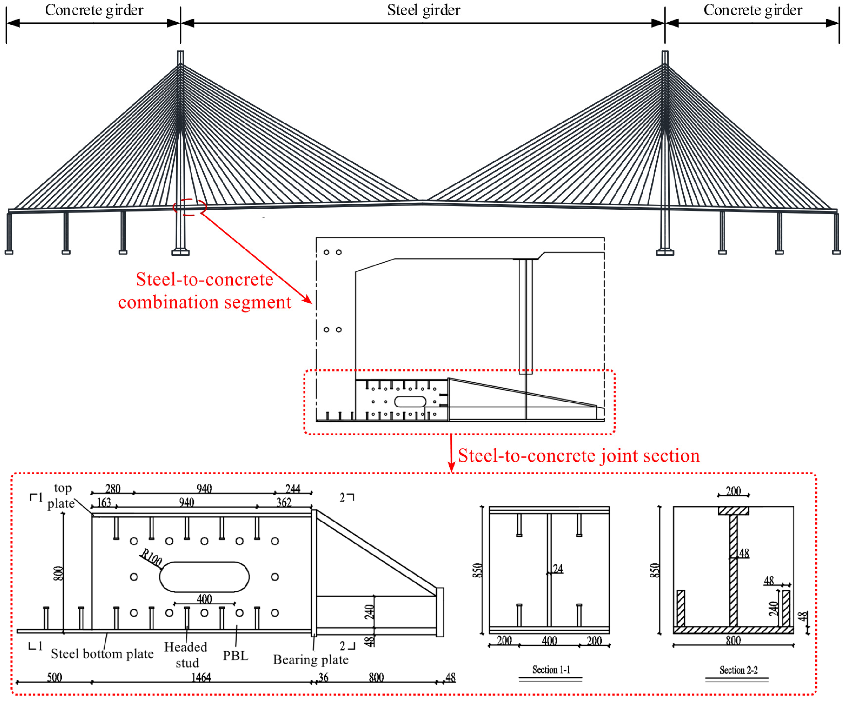
33] designed six SCJS specimens based on the steel–concrete joint section of a hybrid girder cable-stayed bridge. Using a combination of model testing and numerical simulation, the study analyzed the mechanical performance of SCJS with different configurations and obtained the force transmission ratio of key load-bearing components. This paper selects specimen J-1 from the study to validate the simplified calculation model. The structural dimensions of specimen J-1 are presented in
Table 2, and its structural diagram is shown in
Figure 4. In specimen J-1, the connectors transmitted 24.54% of the axial force, while the bearing plate transmitted 75.46% of the axial force.
As shown in
Figure 4, the cross-sectional area of the steel structure in specimen J-1 from reference [
33] varied. In the 500 mm segment, the cross-sectional area of the steel structure consisted only of the bottom plate. In the 1464 mm segment, the cross-sectional area included both the bottom plate and the top plate. Therefore, the model of specimen J-1 was divided into two segments: Segment 1 (500 mm) and Segment 2 (1464 mm).
In the simplified calculation model, the shear stiffness
of the connectors in the
i-th segment can be calculated using Equation (12), where the shear stiffness
of the PBL connectors can be calculated using Equation (23) provided in the Chinese standard [
27], and the shear stiffness
of the shear studs can be calculated using Equation (24) derived from model tests by Lin et al. [
34].
where
represents the diameter of the circular hole in the perforated plate connector (mm).
represents the diameter of the through-bar in the hole (mm).
represents the standard value of the concrete compressive strength (MPa).
where
represents the root diameter of the shear stud (mm).
The simplified calculation model takes into account the effect of cross-sectional variation, with the relevant calculation parameters:
mm2, , , , N/mm, and N/mm.
Based on the structural parameters of specimen J-1, the calculated load transfer ratios of the bearing plate and connectors are shown in
Table 3.
According to the results in
Table 3, the calculated results of the derived simplified calculation model are in good agreement with the example model of specimen J-1, with a maximum error of 0.76%, which verifies the accuracy of the simplified calculation model derived in this paper.
4.2. Verification of the Simplified Calculation Model Through Finite Element Analysis
As described in
Section 4.1, the simplified calculation model shows good accuracy in computing the load transfer effect of the connector and the bearing plate in the SCJS. However, the load transfer effect at the steel beam end is not considered. Therefore, the finite element model (FEM) based on the engineering project is used to verify the accuracy of the simplified calculation model in capturing the load transfer effect at the steel beam end in the SCJS. To validate the accuracy of the FEM, a model that considers only the load transfer effect of the bearing plate and the PBL connector (Condition 3) is first developed. This model incorporates the load transfer components (
a) + (
b), as shown in
Figure 5. The simplified calculation model, validated in
Section 4.1 for the accurate computation of load transfer through the connector and the bearing plate, is then used to verify the modeling approach of the FEM.
Subsequently, FEMs for Condition 1 and Condition 2, which consider the constraint effect at the steel beam end, are developed. The FEM for Condition 1 considers the full load transfer effect at the steel beam end, incorporating load transfer components (
a) + (
b) + (
c), as shown in
Figure 5. The FEM for Condition 2 considers the load transfer effect of the perforated steel plate at the beam end, incorporating components (
a) + (
b) + (
d). In all three FEM conditions, the load transfer at the steel beam end is achieved primarily by adjusting the contact area between the concrete and the beam end.
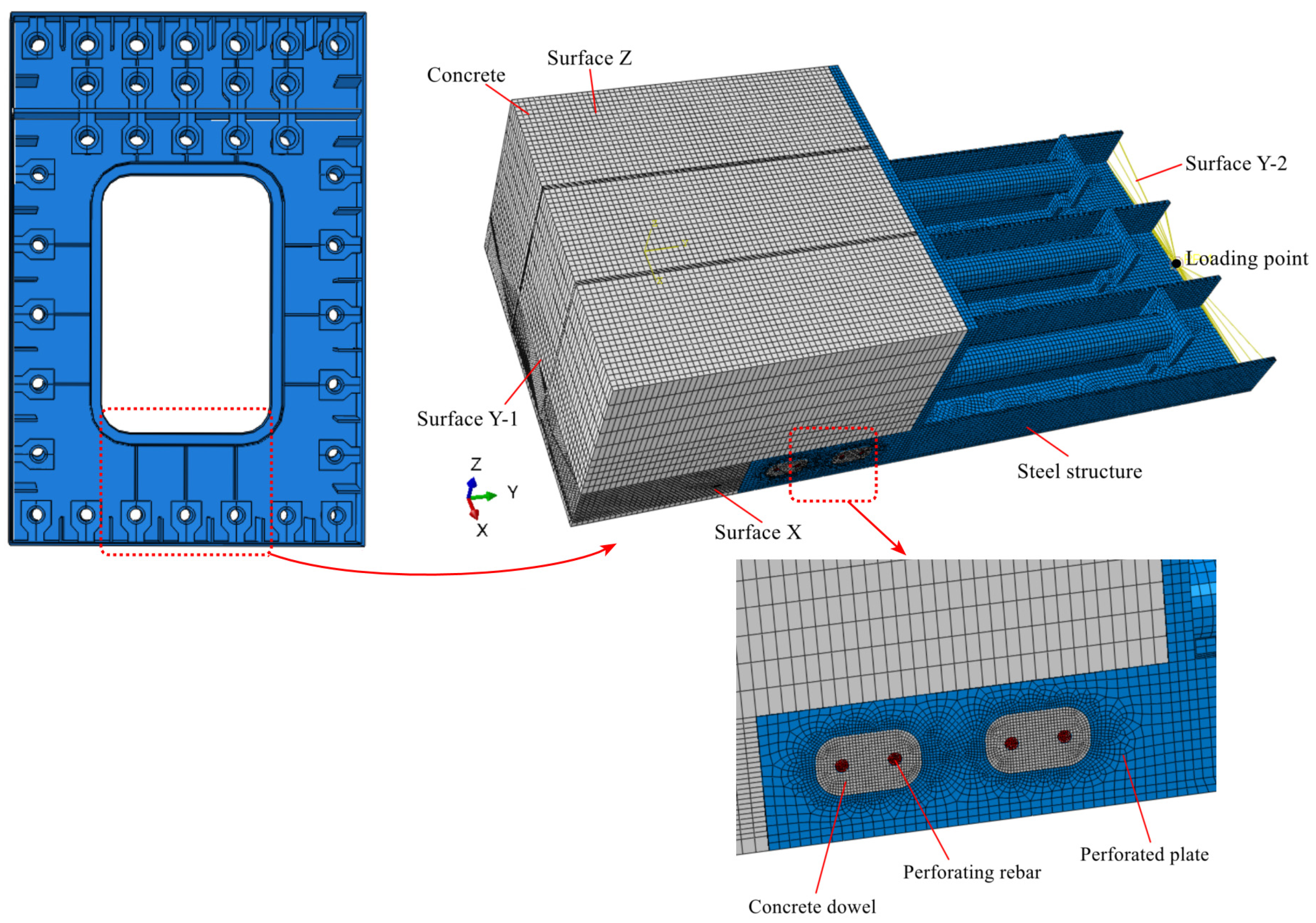
The FEM of the SCJS steel cabin was developed using Abaqus/CAE 2021 software. The dimensions of the steel cabin model are 1.5 m along the X-axis, 1.02 m along the Z-axis, and 3.58 m along the Y-axis. The finite element model of the PBL-stiffened SCJS steel cabin is shown in
Figure 6. To achieve higher accuracy, three-dimensional solid elements (C3D8R) were used to model both the concrete and the steel structure in the steel cabin model. The steel structure was meshed with an element size of 20 mm, while the concrete structure used an element size of 25 mm. A finer element size of 5 mm was applied near the concrete dowels and through-reinforcement to accurately simulate the mechanical behavior of the specimen. Analysis of the element size parameters indicated that this configuration provided sufficiently accurate simulation results. In the actual structure, the steel components are welded to form an integral unit. Therefore, tie constraints were applied to connect all steel components in the FEM [
13,
35]. To accurately simulate the load transfer behavior of the PBL connectors, surface-to-surface contact was applied between the concrete dowels and the perforated steel plates, with a tangential friction coefficient set to 0.5 and normal behavior set as hard contact [
36]. The perforating rebar, primarily subjected to shear forces, was embedded in the concrete. Since the simplified calculation model does not consider the bond friction between the steel structure and the concrete and treats it as a safety reserve, surface-to-surface contact was also used in the FEM for the SCJS interface, with tangential behavior set to frictionless and normal behavior set as hard contact. Boundary conditions were applied as follows: translational constraints in the X-direction were imposed on the X-plane, translational constraints in the Z-direction were imposed on the Z-plane, and all translational and rotational constraints were applied to the Y-1 plane. A loading point was established at the centroid of the Y-2 plane, where an axial force was applied.
The derived simplified calculation model requires dividing the SCJS into multiple segments based on the connectors, and therefore, the model is divided into two segments according to the arrangement of the PBL connectors. Segment 1 has
,
mm
2, and
mm
2. Segment 2 has
mm,
mm
2, and
mm
2. The total load of the model is
= 5,384,000 N,
MPa, and
MPa, and the equivalent support stiffness of the bearing plate is
N/mm. The shear stiffness of the PBL connectors for each segment is
N/mm and
N/mm. The calculated results are shown in
Table 4.
According to
Table 4, the calculated results of the derived simplified calculation model are in good agreement with those of the finite element model in Condition 3, with a maximum error of 4.95%.
Since the simplified calculation model derived in this paper also considers the constraint stiffness of the steel beam ends, it can calculate the load transfer ratio at the steel beam ends. Thus, the simplified calculation model is validated using the refined finite element model of the cabin in the SCJS, including Condition 1 (considering the stiffness of the entire steel beam end) and Condition 2 (considering only the stiffness of the perforated steel plate end). In Condition 1, the contact area between the steel beam end and the concrete is the entire steel beam end area; thus,
mm
2 and
N/mm. In Condition 2, the contact area between the steel beam end and the concrete is the area of the perforated steel plate end; thus,
mm
2 and
N/mm. The calculation results are shown in
Table 5 and
Table 6.
From
Table 5 and
Table 6, it can be seen that the load transfer ratios of each component in the simplified calculation model derived in this paper, which considers the steel beam end constraint, are in good agreement with the results of the FEM, with a maximum error of 5.26%.
In summary, the derived simplified calculation model for the SCJS, which considers the constraint at the steel beam end and the local bearing effect of the bearing plate, demonstrates high accuracy in its results and can be applied to the force transfer calculations of various components within the SCJS under different boundary conditions.
5. Parameter Analysis of the SCJS
Using the derived simplified calculation model, a study was conducted by varying parameters such as the stiffness of the shear connectors, the length of the SCJS, and the axial stiffness of the structure. Since the constraint stiffness of the steel beam end is difficult to control in practical bridge construction and the area of the steel beam end is relatively small, the concrete in contact tends to get damaged. Therefore, for safety purposes, the design considers the most unfavorable effects, ignoring the direct bearing action of the steel beam end and considering only the bearing action of the bearing plate and the shear action of the connectors. Hence, in the simplified calculation model, is set to zero for further calculations.
5.1. The Influence of the Length of the SCJS
To study the effect of varying the SCJS length L on the load transfer of major components (connectors and bearing plates), only the length L of the joint was changed, while maintaining the axial spacing of the connectors and keeping other parameters unchanged. The SCJS length L was varied from 0.5 to 5 times its original length. The derived simplified calculation model was used for analysis, and the results are shown in
Figure 7.
As shown in
Figure 7a, with an increase in the SCJS length, the maximum shear force experienced by the connectors first increases, then slightly decreases, and eventually stabilizes. As the SCJS length increases, the connectors located farther from the bearing plate and closer to the concrete section transfer the largest load. Meanwhile, the connectors located near the bearing plate and toward the middle of the SCJS progressively transfer less load, and the overall transferred load remains relatively low.
As shown in
Figure 7b, the load transferred by the bearing plate decreases as the SCJS length increases, eventually stabilizing. This occurs because, as the SCJS length increases, the number of connectors also increases, which leads to an increase in stiffness. Consequently, more load is transferred by the connectors, resulting in a reduction in the load carried by the bearing plate. When the SCJS length increases beyond a certain point, although the number of connectors increases, the number of connectors involved in load transfer remains almost unchanged. The connectors in the middle region near the bearing plate transfer very little load, and the stiffness does not change further. Therefore, the load transferred by the bearing plate does not continue to change with an increase in SCJS length.
In summary, extending the SCJS length affects the shear capacity of some connectors and does not effectively reduce the maximum shear force experienced by the connectors.
5.2. Effect of Stiffness of Shear Connectors
To study the effect of changes in shear connector stiffness on the load transfer behavior of key components (connectors themselves and bearing plates), the stiffness of the shear connectors was altered, while other parameters of the SCJS remained constant. Specifically, the stiffness was varied by factors of 0.5, 1, and 1.5 times its original value. The results are shown in
Figure 8. As seen in
Figure 8a, as the connector stiffness increases, the load transferred by the connectors located farther from the bearing plate and closer to the concrete section also increases. In contrast, as the SCJS length increases, an increase in connector stiffness causes a reduction in the load transferred by the connectors closer to the bearing plate in the middle section of the SCJS. The change in shear connector stiffness does not alter the overall distribution of shear forces; the connectors farthest from the bearing plate consistently transfer the greatest load.
Figure 8b shows that as connector stiffness increases, the load transferred by the bearing plate decreases. Moreover, as the length of the SCJS increases, the influence of connector stiffness changes on the bearing plate’s load transfer diminishes.
5.3. Influence of Axial Stiffness of Structure
To study the impact of axial stiffness variations on the load transfer characteristics of key components (connectors and bearing plates), the axial stiffness was changed while keeping other segment parameters unchanged. The axial stiffness (EsAs and EcAc) was modified between 0.6 and 5 times the original value, and the results are shown in
Figure 9. As shown in
Figure 9a, the maximum shear force on the connectors increases with an increase in the axial stiffness of the steel structure (EsAs), eventually reaching a stable value. In contrast, as the axial stiffness of the concrete structure (EcAc) increases, the maximum shear force on the connectors decreases and eventually stabilizes. As shown in
Figure 9b, with an increase in the axial stiffness of the steel structure (EsAs), the load transfer ratio of the bearing plate decreases, eventually becoming constant. Conversely, as the axial stiffness of the concrete structure (EcAc) increases, the load transfer ratio of the bearing plate also increases. Therefore, when designing segment connectors, to control the maximum shear force of the connector group, measures such as increasing the height of the concrete cabin or reducing the thickness of the steel plate can be adopted. However, this will also lead to an increase in the proportion of the load directly transferred from the bearing plate to the concrete.
6. Conclusions
This study focuses on the simplified calculation model of the SCJS. Based on this model, the effects of variations in shear connector stiffness, joint length, and axial stiffness on the load transfer performance of the bearing plate and connectors are investigated. The following conclusions can be drawn:
- (1)
The derived simplified calculation model of the SCJS, which incorporates the steel beam end restraint, the local bearing effects of bearing plates, and cross-sectional area variation, demonstrates high accuracy. The model comprehensively considers multiple factors and is applicable to the analysis and calculation of the SCJS under diverse boundary conditions.
- (2)
The length of the SCJS, within a certain range (0.5 L to 2 L), affects the maximum shear force on the connectors. However, when the SCJS length is excessively extended, it reduces the effectiveness of certain connectors in resisting shear without significantly decreasing the maximum shear force they experience.
- (3)
Variations in connector stiffness significantly affect connectors farther from the bearing plate and closer to the concrete segment but do not alter the shear force distribution among them. Increasing connector stiffness reduces the load carried by the bearing plate. However, as the SCJS length increases, the effect of connector stiffness variation on the load transferred by the bearing plate diminishes.
- (4)
With an increase in the axial stiffness of the steel structure (EsAs), the load transferred by the connectors initially increases and then stabilizes, while the load transferred by the bearing plate initially decreases and then stabilizes. In contrast, an increase in the axial stiffness of the concrete structure (EcAc) produces the opposite effect.
Based on the study of the simplified calculation model, the load transfer mechanism of the SCJS can be summarized as follows: Under axial force, the majority of the axial force is directly transferred to the concrete through the bearing plate, while the remaining portion is transferred along the steel structure within the SCJS. During this transfer process, part of the axial force is transferred to the concrete through PBL connectors, and another part is transferred through the steel beam end. The bearing plate, PBL connectors, and steel beam end collectively form the primary load transfer components of the SCJS. This conclusion is consistent with the findings of related studies cited in the Introduction, further validating the rationality and reliability of the simplified calculation model. The derived simplified calculation model enables rapid determination of load distribution among the primary load transfer components, facilitating the assessment of the load-bearing capacity of the SCJS. Compared with high-cost model tests or numerical simulations, the simplified calculation model significantly improves design efficiency. The regular conclusions derived from parameter analysis provide scientific guidance for structural optimization and serve as a reference for the design and analysis of similar structures. Current research on SCJS mainly focuses on mechanical performance and shear connectors. These findings further enrich the theoretical framework of SCJS and have significant value in both engineering applications and academic research. The accuracy of the simplified calculation model is influenced by the stiffness of shear connectors between steel and concrete. Therefore, determining connector stiffness that better reflects the behavior of actual structures is a key direction for further research.


