Article

Numerical Simulation of Nuclear Power Plant Pile Foundation Damage Under Earthquake Action

1
Key Laboratory of Earthquake Engineering and Engineering Vibration, Institute of Engineering Mechanics, China Earthquake Administration, Harbin 150080, China
2
Key Laboratory of Earthquake Disaster Mitigation, Ministry of Emergency Management, Harbin 150080, China
3
First Crust Monitoring and Application Center, China Earthquake Administration, Tianjin 300180, China
*
Author to whom correspondence should be addressed.
Buildings 2024, 14(11), 3617; https://doi.org/10.3390/buildings14113617
Submission received: 9 October 2024 / Revised: 1 November 2024 / Accepted: 6 November 2024 / Published: 14 November 2024
(This article belongs to the Section Building Structures)

Abstract

:
This study investigates the pile foundation of a nuclear power plant situated on medium-soft soil. It employs an improved viscoelastic artificial boundary unit to accurately simulate the boundary conditions of the calculation area. The research utilizes a constitutive model of concrete damage plasticity for the pile foundation and an equivalent linearized model for the soil layer. Through large-scale shaking table experiments and numerical simulations, we explore the internal force distribution within the nuclear power structure’s pile foundation and assess the extent of the damage. The results indicate that damage primarily occurs in the medium-soft ground, concentrating in the upper part of the pile and affecting the entire cross-section. Subsequent numerical analyses were conducted after reinforcing the soil layer around the top of the pile. The findings demonstrate that this reinforcement leads to a more uniform and rational distribution of internal forces along the pile, significantly reducing damage. Notably, there is no severe damage extending across the entire cross-section after reinforcement. This outcome highlights the potential for improving the force distribution in the pile foundations of nuclear power structures through appropriate soil layer reinforcement. The insights gained from this study provide valuable guidance for the seismic design of nuclear power structures.

1. Introduction

In constructing nuclear power plants, non-bedrock sites typically consist of two main components: the foundation and the superstructure. The design of the superstructure must withstand extreme conditions and possess a high seismic capacity. Therefore, ensuring the safety of nuclear power structures during earthquakes makes the seismic design of foundations in non-bedrock locations a crucial aspect of nuclear power plant design.
Earthquake investigations reveal that pile foundations generally exhibit good seismic performance. However, there are instances where damage to pile foundations in soft soil sites is more severe. Notable examples include the 1948 Fukui earthquake (M = 7.3) [1], the 1952 Tokachi earthquake (M = 8.1) [1], the 1976 Tangshan earthquake (M = 7.8) [2], the 1978 Miyagi Prefecture earthquake (M = 7.2) [1], the 1985 Mexico earthquake (M = 8.1) [3], and the 2008 Wenchuan earthquake (M = 8.0) [4]. These events demonstrated significant damage to pile foundations in soft ground, resulting in the destruction of buildings.
Given the complexity of interactions among rock, soil, and pile foundations, as well as the hidden nature of seismic damage and the challenges of post-damage repairs, many scholars have undertaken experimental and theoretical research on the seismic performance of pile foundations. Most existing studies focus on the design of pile foundations for industrial and civil structures [5,6,7,8,9,10,11,12,13,14,15,16,17], including high-rise buildings, bridges, factories, wharves, and marine platforms. Researchers have summarized the damage phenomena of pile foundations during earthquakes and analyzed their stress under seismic action, including studies on multilayered soil sites. These contributions provide valuable insights for the seismic design of pile foundations in industrial and civil contexts, serving as a reference for further research on the seismic damage mechanisms of these foundations.
Significant progress has also been made in soil–pile interaction tests and numerical calculations. For instance, Zhao et al. [18] conducted shaking table tests using group piles on in-ground load-bearing platforms, highlighting that dynamic soil pressure on the front side of the load-bearing structure plays a crucial role in the coordinated operation of the load-bearing platform, foundation piles, and foundation soil. Xie et al. [19] investigated pile–soil–structure interactions through shaking table tests, noting that interaction decreases as the peak ground vibration increases and that higher-order vibration modes of the superstructure significantly affect seismic response. Xu et al. [20] reported that during dynamic response, the bending moment of the pile foundation exhibits a pattern of small bending moments near the top and larger ones near the bottom, with abrupt changes at the soil layer interface. Advances in dynamic soil–pile–structure interaction theory and modern computational technology have led to more sophisticated numerical models and algorithms, improving calculation accuracy and stability in simulating the vibration characteristics of semi-infinite soil bodies. Wolf and Von Arx [21] were pioneers in using complete dynamic response analysis to assess group pile effects, revealing that frequency, number of piles, and spacing significantly impact results. Yang [22] utilized ANSYS finite element software to analyze the sensitivity of parameters in the pile–soil–structure interaction system, particularly the effects of soil liquefaction on the foundation pile’s dynamic response. Kumar et al. [23] employed PLAXIS3D to study the response characteristics of pile–raft composite foundations under seismic loading, validating numerical simulations against centrifuge test results, which were found reasonable. Wang et al. [24] used OpenSees to create a finite element model of a soil–pile–bridge structure, conducting nonlinear dynamic and pushover analyses. Their computational results aligned well with experimental outcomes, proposing parameters for superstructure engineering requirements to assess the seismic demands on pile foundations and the post-seismic load-carrying capacity of bridges.
The above studies satisfy the seismic design requirements of pile foundations for general industrial and civil buildings to a certain extent. However, whether they can meet the seismic design requirements of pile foundations for nuclear power plants needs to be demonstrated through a large number of studies. The number of nuclear power plants built on pile foundations in foreign countries is relatively small, and the seismic research on nuclear power plants using pile foundations is also limited. Through the evaluation of the seismic effect of using pile foundations for general construction, it is believed that, with proper design [25] and a reasonably selected supporting soil layer for the pile foundation, the seismic effect of the pile foundation is good. This understanding forms the basis for the seismic study of pile foundations for nuclear islands. In recent years, some foreign scholars [26,27,28,29,30] have actively explored the seismic design of nuclear power pile foundations, which provides valuable experience for the seismic design of nuclear power pile foundations, and also provides a reference for further research on the seismic failure mechanism of nuclear power pile foundations. In China, the research on seismic design of nuclear power pile foundations has also achieved some valuable results; Zou and others [31] have developed a refined model of AP1000 and studied the seismic dynamic response of a pile-based nuclear island plant. Qiu and Yin et al. [32] studied the water intake system of a nuclear power structure. They utilized ANSYS finite element software to create a dynamic interaction model of pile–soil–nuclear power intake structure interaction. Based on the calculation results, they proposed a reinforcement scheme for safety reserves and weak links. Chen et al. [33] introduced a soil–junction interaction partitioning algorithm that combines modal superposition and time-step integration. The study results indicated that the structural damping model minimally impacts the site’s response but significantly affects the structural response. This finding offers a basis for the rational selection of the damping model.
Since the superstructure selected in large-scale seismic simulation shaking table tests is generally a lighter quality steel frame structure, the pile foundation mostly uses steel piles to simulate the dynamic pile–soil–structure interaction. Therefore, in large-scale shaking table tests, rarely does the seismic damage phenomenon appear in pile foundations, especially those for nuclear power plants. There has been even less research on the seismic action damage mechanism for this special structure’s pile foundations. Jing et al. [34] conducted shaking table tests of a pile-based nuclear island structure model and studied the dynamic response of the pile-based nuclear island structure through experiments. They had a preliminary understanding of the damage mechanism of the soil–soil–pile–structure seismic response of a nuclear power structure’s pile foundations. Based on an understanding of the macro phenomenon of this experiment, this paper uses the pile foundations of a nuclear power plant in medium-soft soil as an example. It simulates the seismic response characteristics of the nuclear power plant’s pile foundation under seismic load using ABAQUS 6.14 meta-software. The paper compares the macro damage phenomenon of the nuclear power pile foundation with that of the shaking table test. It is numerically verified that the pile foundation of the nuclear power plant in medium-soft soil can significantly improve the internal force distribution of the pile body. This improvement helps in mitigating earthquake damage and saving construction costs by appropriately strengthening the soil in a certain range at the top of the pile. The study also confirms that appropriate reinforcement of a certain range of the soil body at the top of the pile can greatly enhance the internal force distribution of the pile body. This enhancement helps in mitigating seismic damage and reducing project costs. These findings provide an important reference for the seismic design of pile-based nuclear power structures.

2. Materials and Methods

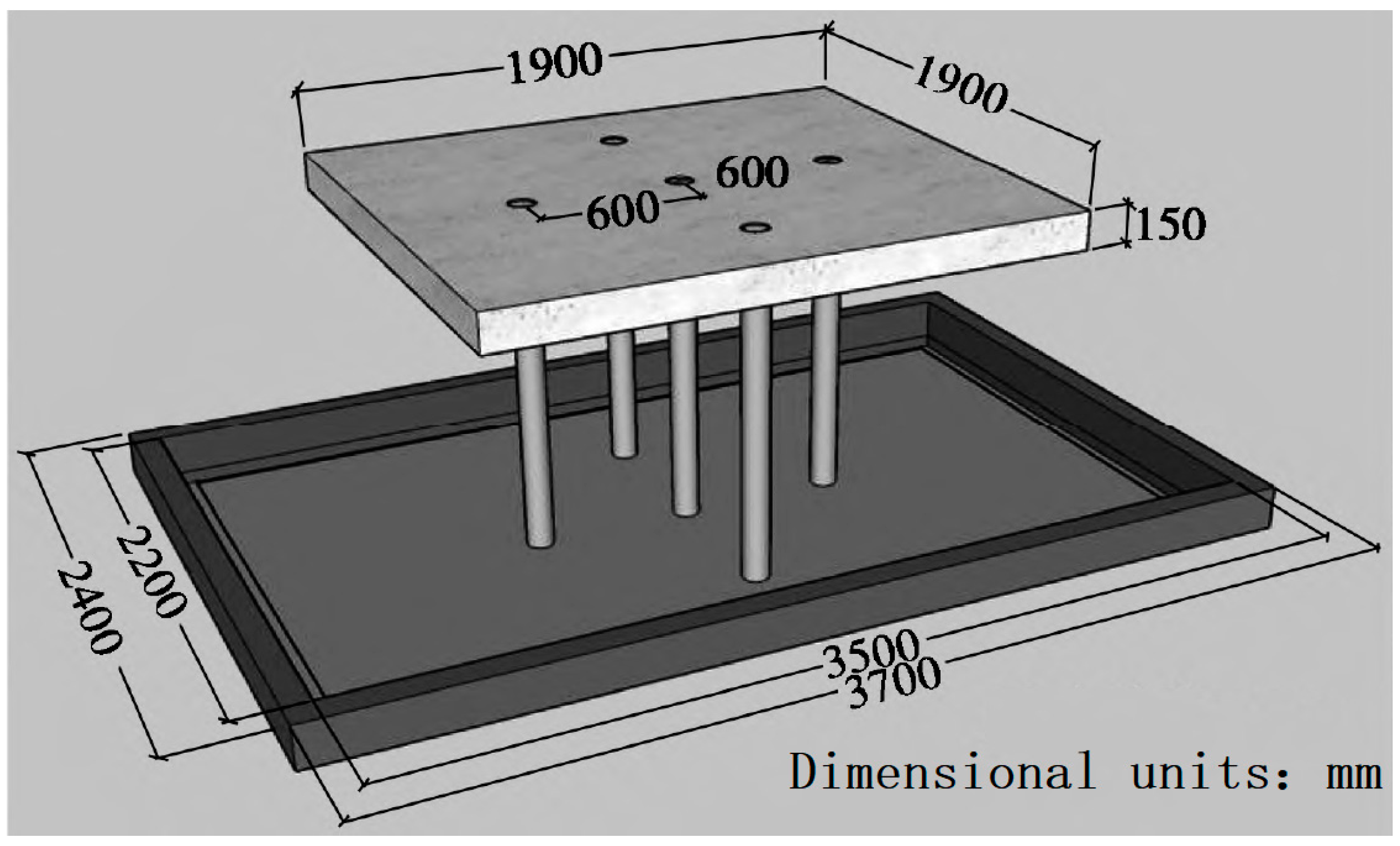
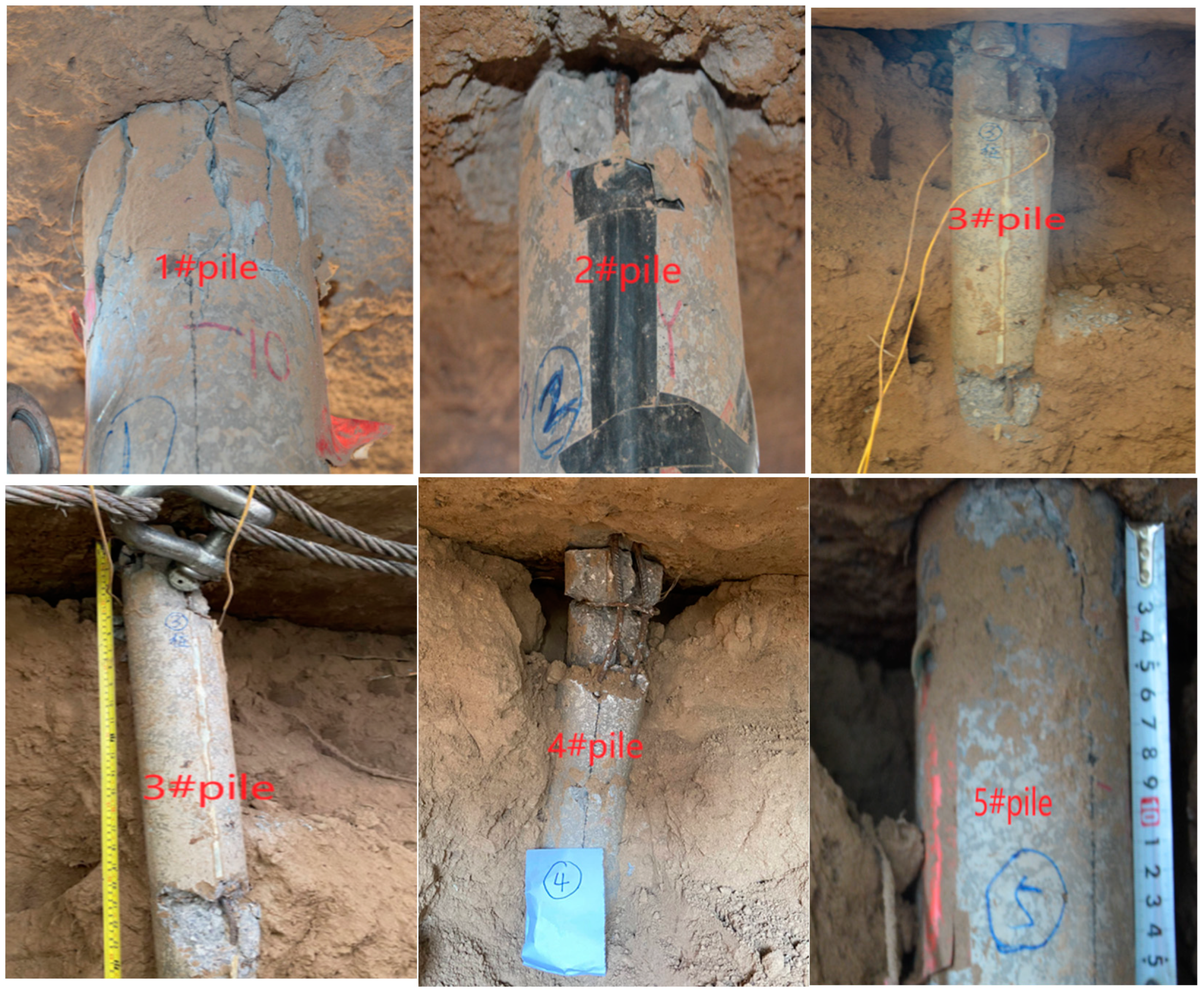
2.1. Macro Experimental Phenomena

The group piles are arranged as illustrated in Figure 1, with the vibration direction along the line connecting piles 1, 5, and 3, and the detailed test process is outlined in the literature [34]. The focus is on the damage observed in the pile foundation of a soft soil pile-based nuclear island structure, as depicted in Figure 2. As shown in Figure 2, the top of the pile and the connection to the loadbearing platform exhibit varying degrees of damage. The top of the No. 3 side pile shows severe damage in the direction of vibration, with fracture occurring at about 1/3 of the pile’s height. The top of the No. 1 side pile displays numerous vertical cracks, with slightly less damage compared to the No. 3 pile. The top of the No. 4 corner pile is crushed and fractured, indicating serious damage. The No. 2 corner pile and its connection to the bearing platform show concrete dislodging and rebar exposure, with damage less severe than the No. 4 corner pile. The No. 5 center pile sustains relatively light damage compared to the No. 4 corner pile. The No. 5 side pile and corner pile exhibit lighter damage, with only some vertical cracks at the pile tops.

2.2. Computational Model

The superstructure in this paper is a reactor-type nuclear power plant, including the reactor plant, fuel plant, electrical plant, safety plant, etc. All the plants share a raft with a thickness of 2.2 m. Apart from the reactor plant, the other nuclear power plants have a general wall and plate structure. The wall thickness is 800 mm, plate thickness ranges from 500 to 600 mm, with approximately 10 layers. The static pressure at the basement is about 550–600 kPa. The total height of the reactor plant is around 80 m, utilizing a large-volume double-layer containment. The inner layer is 1.3 m thick, the outer layer is 1.8 m thick, and the static pressure at the base of the reactor plant is about 800 kPa.
In this study, the general finite element software ABAQUS [35], widely used in geotechnical engineering, was employed for modeling and calculation. The pile layout is shown in Figure 3, with a pile diameter of 1.5 m and a pile length of 47.8 m. The pile foundation is embedded in bedrock at the bottom, with a layered soft soil layer of 48 m in thickness above it, and the bedrock thickness is set to 10 m. The finite element model of the layered soil is illustrated in Figure 3. The upper structure of the nuclear power plant was modeled to include the containment structure and surrounding buildings, where the containment material is C80 concrete and the surrounding buildings are made of C35 concrete. The specific parameters for the soil and concrete materials are detailed in Section 2.2. Following the recommendations of Zou et al. [31], a “3× model” was used to ensure sufficient computational accuracy.
Abaqus has limitations in handling artificial boundaries, requiring secondary development to incorporate suitable artificial boundaries in dynamic calculations. This study uses viscoelastic artificial boundary elements as the artificial boundary, with specific details discussed in Section 3.1. A finite element model of soft soil was established, focusing mainly on the response of the pile foundation, with a simplified model for the superstructure. The reactor containment was discretized using hexahedral solid elements (C3D8R), totaling 3324 elements, while the surrounding buildings were discretized using quadrilateral shell elements (S4R), resulting in a total of 3732 elements. The pile foundation was discretized with hexahedral solid elements (C3D8R), totaling 64,920 elements, and the soil was also discretized with hexahedral solid elements (C3D8R), resulting in a total of 150,060 elements. The pile–soil interaction was simulated using a tied contact without separation. The finite element model is shown in Figure 3.

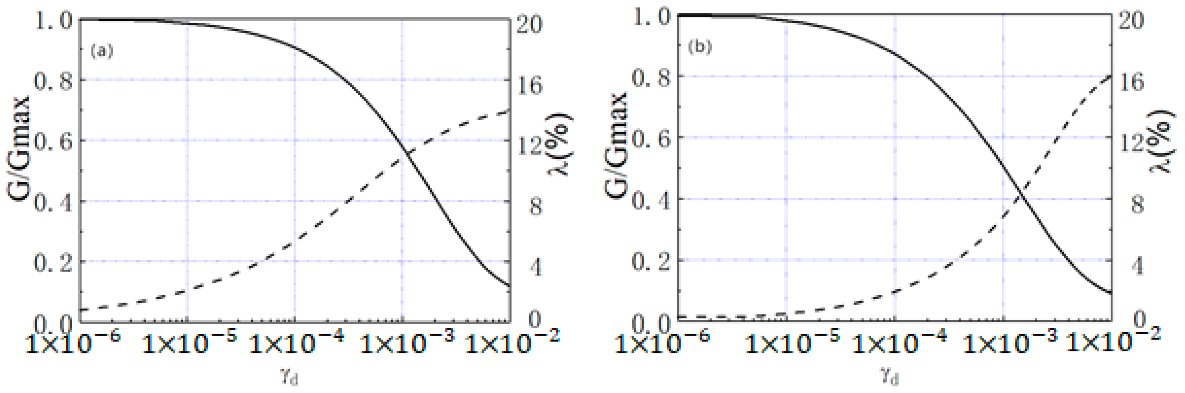
2.3. Calculation Parameters

In software was utilized to calculate the equivalent parameters of the soil layer based this paper, the soil layer parameters were determined using the equivalent linearization method. EERA [36] one-dimensional equivalent linearization on the results of the geodynamic test G/Gmaxd, λ~γd relationship (G/Gmax—dynamic shear modulus ratio, γ—dynamic strain, λ—dynamic damping ratio). The relationship of the soil body G/Gmaxd, λ~γd is illustrated in Figure 4, and the specific equivalent parameters of the soil layer are presented in Table 1.
Concrete was used for both the nuclear island superstructure and the pile foundation. Considering that the nuclear island structure has a high safety margin and is unlikely to be damaged under typical seismic loads, the upper concrete is a linear elastic eigen structure [37]. C80 concrete was utilized for the upper nuclear island structure, and the material parameters are detailed in Table 2. Since the pile foundation has been the subject of less research and is less often applied for nuclear power structures, and could potentially be a weak link in the system, more attention should be given to the stress and damage of the pile foundation under seismic activity. Therefore, the pile foundation was designed to use a concrete plastic principal structure, with its stress–strain relationship following the relevant provisions in Appendix C.2 of the Code for the Design of Concrete Structures GB50010-2010 [38]. To minimize calculation costs, no steel reinforcement was included in this model. To approximate the effect of steel reinforcement, the tensile properties of the concrete were adjusted to be symmetric with the compressive properties, demonstrating that reinforced concrete in tension and compression exhibits similar mechanical characteristics. The stress–strain relationship is illustrated in Figure 5. C35 concrete was chosen for the pile foundation, with some material parameters outlined in Table 2.
In addition, the damage factor of concrete is expressed using the following equation
D = 1 σ ε E 0
In the above equation, D represents the concrete damage factor, ε represents strain, σ represents the corresponding stress, and E0 represents the tangent modulus at the origin.

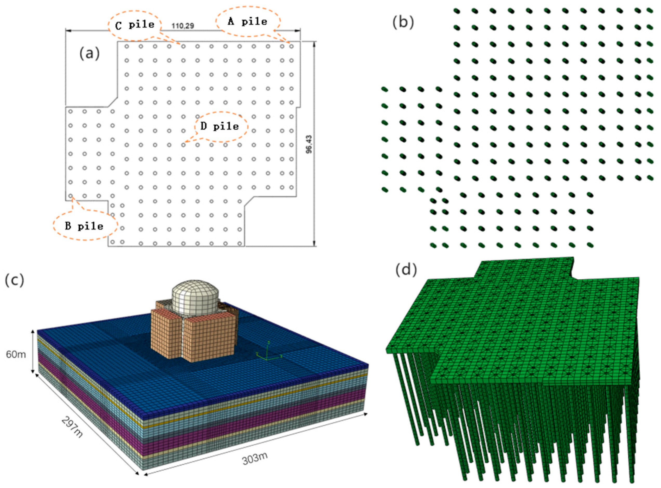
2.4. Finite Element Model

The finite element soft computing model was established. The calculation mainly considers the reaction of the pile foundation, while the superstructure was modeled using simplified modeling. The mesh was divided into the reactor containment with hexahedral solid-cell discretization, totaling 3324 cells. The other plants used quadrilateral shell-cell discretization, totaling 3732 cells after discretization. The pile foundation was discretized using hexahedral solid cells, resulting in a total of 64,920 cells. The soil body was discretized using hexahedral solid units, with a total of 150,060 units after discretization. The pile–soil contact employs non-separating bound contact. The finite element model is illustrated in Figure 3c.
The artificial boundary can allow the outgoing scattered waves to pass through or be absorbed, simulating the effect of a semi-infinite domain on the computational region. In this study, we utilized the viscoelastic boundary unit introduced by Gu [39], iu [40] and Wang [41] as the artificial boundary, enhancing it by integrating examples from this research. This boundary unit, along with the viscoelastic artificial boundary, offers comparable accuracy. Its key benefit lies in its ease of application, preventing errors stemming from significant deformation of the boundary unit. The primary parameters are as follows
E ~ = α N G R · b 1 + μ ~ 1 2 μ ~ 1 μ ~
β ~ 2 D = ρ R 2 G ( C s α T + C p α N ) β ~ 3 D = ρ R 3 G ( 2 C s α T + C p α N )  
When large deformations are considered, the viscoelastic boundary cell is improved [42] by imposing cell size limits on the viscoelastic boundary cell
h 10 · max d
In the above equation, E ~ denotes the equivalent modulus of elasticity of the boundary unit, β ~ 2 D and β ~ 3 D are the equivalent stiffness damping coefficients of the boundary unit of the two-dimensional and three-dimensional models, respectively. α N and α T are the boundary parameters, and the specific values are shown in Table 3. μ ~ denotes the equivalent Poisson’s ratio of the boundary unit, which is set to 0 in this paper. C s , C p , G and ρ represent the shear wave velocity, compression wave velocity, modulus of elasticity, and density. R denotes the distance from the wave source to the artificial boundary point, h denotes the size of the boundary unit, and d denotes the maximum displacement of the input ground shock. In this scenario, the maximum displacement of the ground vibration in the horizontal direction is 0.63 m, and in the vertical direction, it is 0.17 m. The size of the boundary unit in the horizontal direction is 7 m, and in the vertical direction, it is 3.5 m.

2.5. Input Ground Motion Time History

The earthquake motion is represented by the artificial seismic acceleration time history provided by Song [37], classified as SL-2 (Ultimate Safety Ground Motion) level. The acceleration was converted into equivalent seismic loads using the substructure-based input method proposed by Liu [40], enabling the application of seismic loads. The ground shaking level was SL-2 (Ultimate Safety Ground Motion) level, with a peak acceleration in the horizontal direction of 0.30 g. The duration of seismic motion is 40.96 s, and the seismic acceleration time history curve is illustrated in Figure 6.

3. Results and Discussion

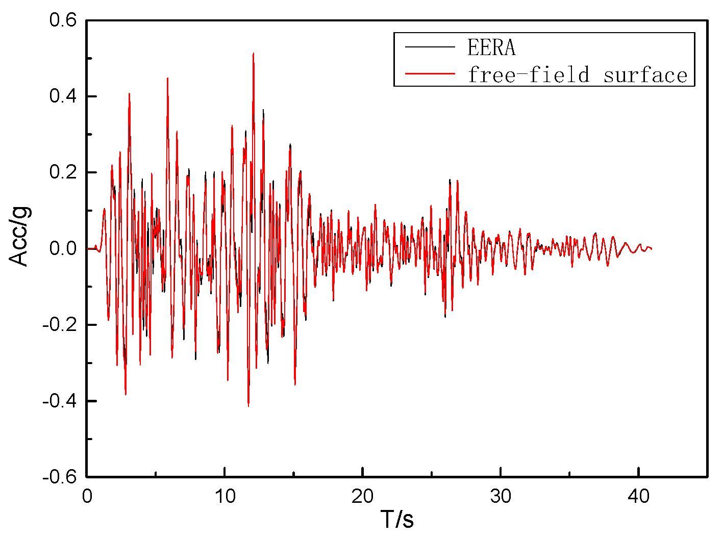
3.1. Free-Field Verification

To validate the effectiveness and reasonableness of the artificial boundary condition in the finite element method, the free-field seismic response was computed using both the finite element method and the equivalent linearized EERA method for soil layer seismic response. Under identical horizontal seismic acceleration time history input conditions, the horizontal acceleration time history of the free surface calculated by the two methods is plotted in Figure 7. The results demonstrate a strong agreement between the two methods, indicating that the artificial boundary condition employed in the finite element method of this study performs effectively.

3.2. Distribution of Internal Forces in Pile Body

Figure 8 shows the bending moment envelope, shear force envelope, and axial force distribution (where positive values indicate tension) for the four piles depicted in Figure 3a. The figure reveals that the bending moment is more pronounced in the upper third of the pile body. The distribution of bending moments is complex, with peak shear forces primarily observed at the pile head and pile bottom. Although there is no clear correlation between the bending moment and shear force with the pile location, the axial force exhibits a notable correlation. Angular piles experience the highest axial forces, followed by the side piles, while the center piles have the lowest axial forces. This indicates that angular piles are more susceptible to damage under ground vibrations.

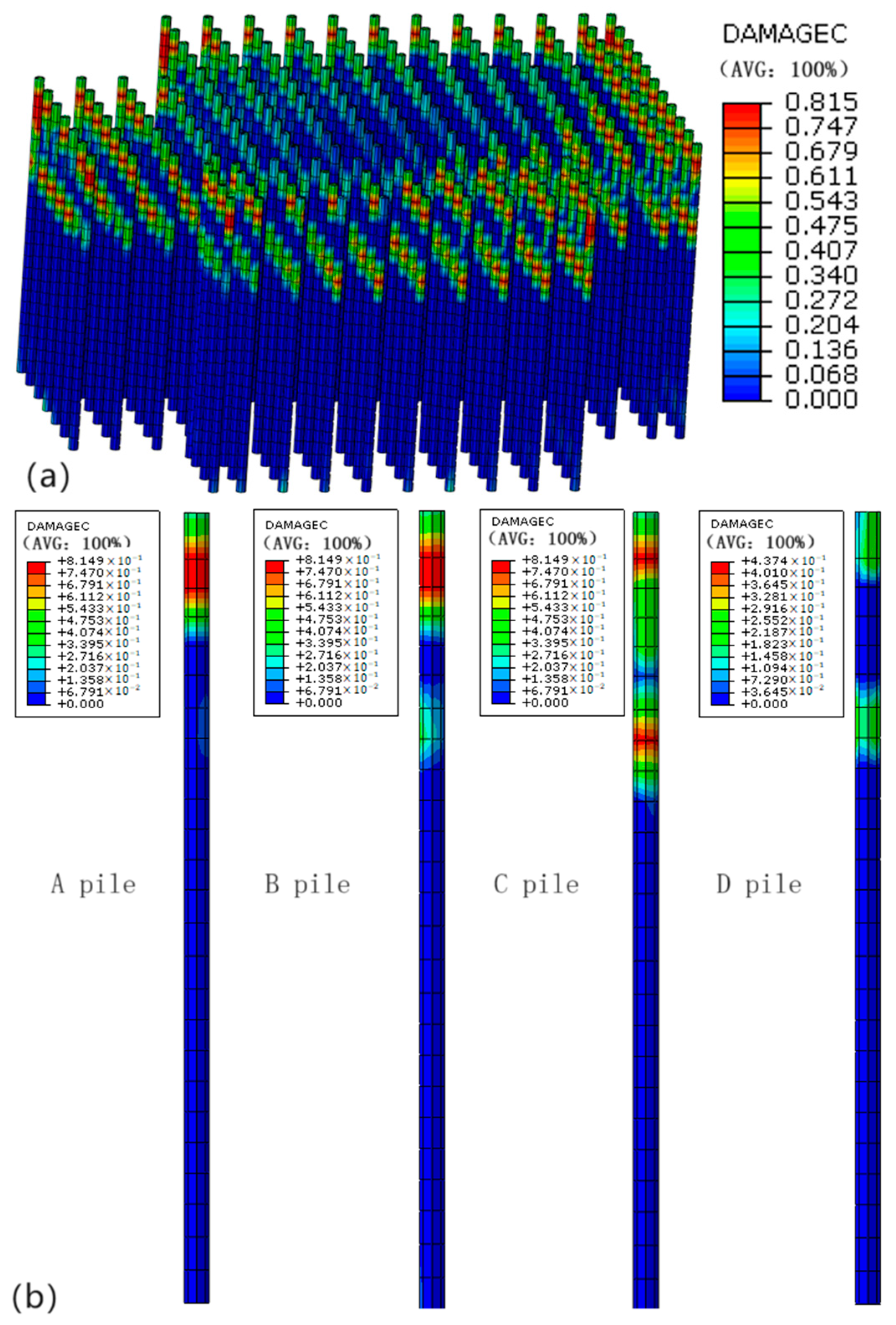
3.3. Pile Damage Distribution

The concrete damage factor D, which represents the concrete strength reduction coefficient, is determined by Equation (1) in the text and can be directly extracted from the model. Figure 9 illustrates the main damaged areas of the pile body, showing that damage predominantly occurs near the pile head. The damage was more pronounced in the corner piles, while it was less significant for piles closer to the center. Specifically, corner piles A and B experience maximum damage values exceeding 0.85, resulting in complete damage to the entire cross-section at the pile head and a loss of load transfer capacity. As a result, the damage did not propagate downward, which explains the lack of correlation between the bending moment and shear force for the single pile position. For side pile C, damage was most severe at heights of 45 m and 35 m, with a maximum damage value of approximately 0.8. In contrast, center piles D show less significant damage, with a maximum damage value of less than 0.3.

4. Seismic Response Analysis of Pile Foundation After Soil Reinforcement

From Figure 8 and Figure 9, it can be seen that the bending moment and shear force of the pile foundation were larger in the upper 1/3 of the pile body, and the damage of the pile body was mainly concentrated in this area, which is consistent with the results of the shaking table test [34]. Obviously, the force distribution of the pile foundation at this time is very unreasonable, so it should be properly reinforced. This paper proposes a treatment program for the soil around the pile foundation, which indirectly changes the internal force distribution of the pile body, making it more reasonable and reducing the damage to the pile body.

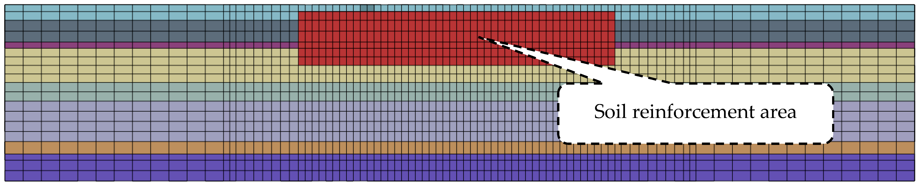
4.1. Soil Reinforcement Scheme

According to the scope of application of the Design Standard for Nuclear Power Plants, seismic calculations for the foundations of nuclear power plants are applicable to foundations with a static bearing capacity eigenvalue greater than 0.34 MPa or a shear wave velocity greater than 300 m/s. Therefore, the shear wave velocity in the reinforced area is set at 302.6 m/s. The 17.3 m of soil below the raft slab is treated as illustrated in Figure 10, and the parameters of the treated soil are presented in Table 4.

4.2. Internal Force Distribution of Pile Body After Reinforcement

The internal forces in the piles after soil treatment are shown in Figure 11. Compared to Figure 8, there is a significant change in the internal forces at the pile tops. The maximum bending moments in the X-direction near the tops of piles A, B, C, and D decreased from 8.6, 7.3, 5.2, and 7.6 × 10³ KN∙m to 1.2, 1.5, 1.0, and 0.9 × 10³ KN∙m, respectively. In the Y-direction, the maximum bending moments decreased from 7.9, 7.8, 8.0, and 8.7 × 10³ KN∙m to 1.3, 1.2, 1.2, and 0.9 × 10³ KN∙m, respectively. The maximum shear forces reduced from 7.7, 6.8, 6.9, and 5.1 × 10³ KN to 2.7, 2.6, 2.6, and 1.4 × 10³ KN, and in the Y-direction, the maximum bending moments decreased from 4.8, 4.8, 3.3, and 5.1 × 10³ KN∙m to 2.5, 3.3, 3.1, and 1.9 × 10³ KN. This indicates a significant reduction in the internal forces at the pile tops. The shear force distribution along the piles became more reasonable, with shear forces distributed more uniformly, enabling the pile foundation to bear the shear forces more effectively. The axial forces in the piles still followed the trend of the corner piles experiencing the maximum forces, followed by the edge piles, with the center piles experiencing the minimum forces.
These calculation results indicate that reinforcing the soil in a specific range around the pile tops improves the overall horizontal stiffness of the soil–pile interaction, enhancing the ability of the soil–pile system to resist lateral seismic loads. This effectively reduces the bending moments and axial forces in the piles, making the stress distribution at the weak points of the pile tops more reasonable.

4.3. Pile Damage Distribution After Soil Reinforcement

The internal force of the pile body after soil treatment is depicted in Figure 12. Compared with Figure 9, the internal force of the pile body has changed significantly. This change is mainly evident in three aspects: (1) The distribution of the bending moment in the pile body is more rational, showing a correlation in the location of individual piles. The bending moment is highest in the middle pile, followed by the side pile, and the corner pile has the least bending moment. (2) The distribution of the shear force in the pile body is more logical, with a more uniform distribution along the pile. The entire pile foundation experiences shear force. (3) The axial force in the pile body still follows the pattern where the corner pile experiences the highest axial force, followed by the side pile, and the middle pile experiences the lowest axial force. Overall, after the treatment of the soil layer, the distribution of forces in the pile body is more rational.

4.4. Discussion

  • The numerical calculations of the nuclear island pile group, along with the shaking table test results by Jing Liping [34], indicate that:
    (1)
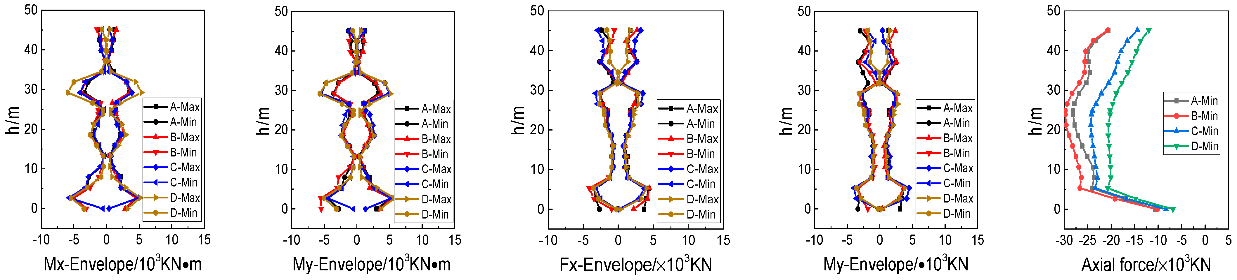
    The shear force in the piles is greatest at the pile–cap connection and decreases with depth, while the bending moments are larger at the pile tops and in the upper-middle regions;
    (2)
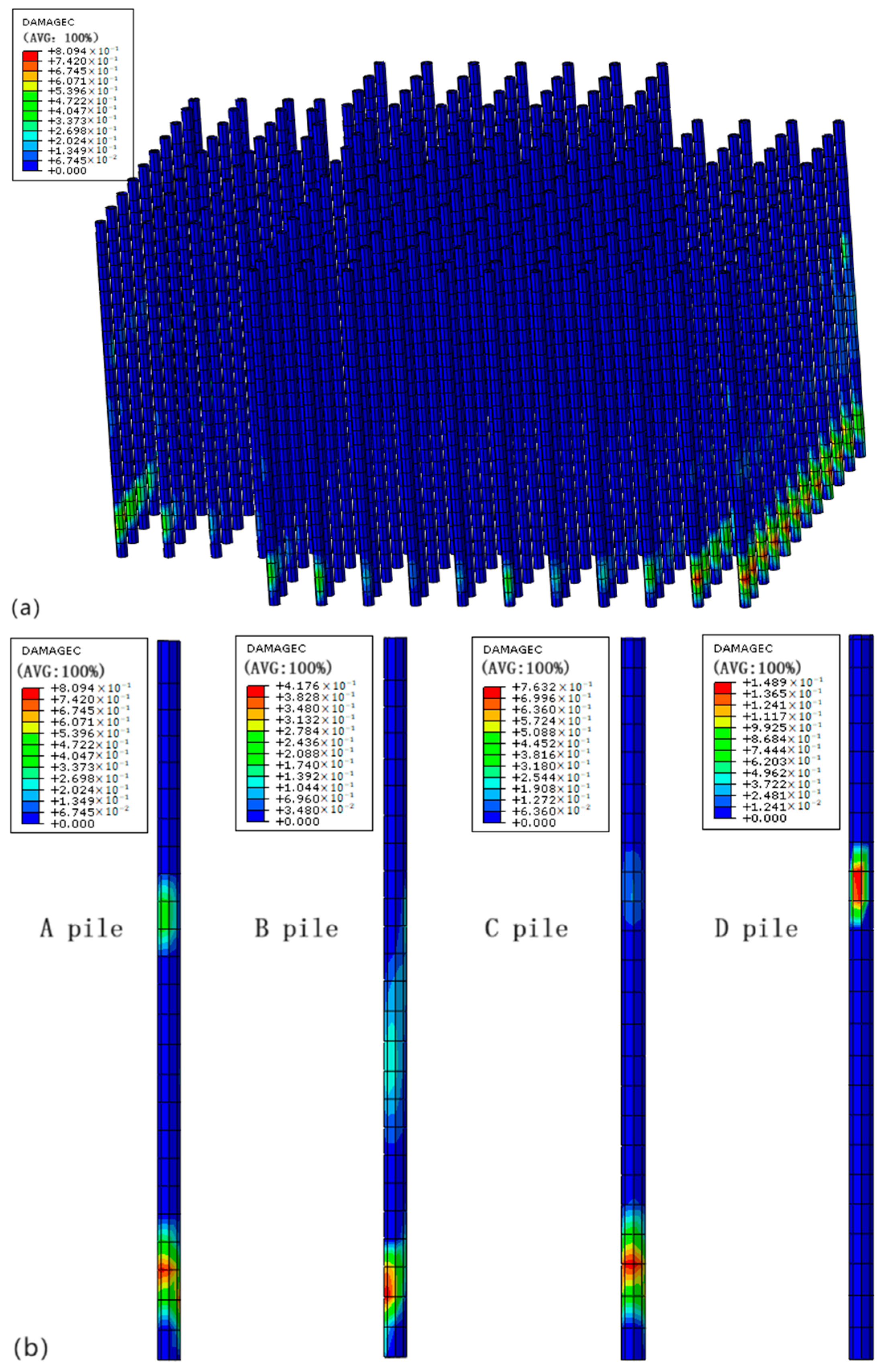
    Damage to the nuclear island plie group occurs at the pile tops and in the lower one-third of the pile length;
    (3)
    The extent of the damage is greatest in the corner piles, followed by the edge piles, with the center piles sustaining the least damage. The primary reason for these results is that the mass and stiffness of the nuclear island structure are significantly greater than those of the pile foundation, creating weak points near the pile–cap connection, especially at the corner piles, making them more prone to damage under seismic loading.
  • This paper utilizes numerical methods to investigate the seismic response of the nuclear island pile foundation after reinforcing the surrounding soil within a certain range. Appropriate reinforcement can significantly alter the stress state at the pile tops under seismic loads, thus reducing damage to the group piles. However, determining the most economical type of soil reinforcement and the optimal range requires more detailed numerical simulations and indoor shaking table tests to provide recommendations with greater engineering application value.
  • The viscoelastic boundary used in this study is detailed in Wang Zhan’s [41] paper. This boundary condition effectively mitigates the influence of excessive deformation in boundary elements on the computational results, while also considering the relationship between the dimensions of the boundary elements and their potential maximum deformations. This approach maintains computational accuracy and simplifies the pre-processing of the software.
  • This paper assumes that concrete exhibits symmetric tensile/compressive properties, which may lead to an underestimation of concrete damage. In reality, the initial development of cracks in the concrete may be greater than assumed, resulting in a higher level of early damage. As damage progresses to a certain stage, the surrounding concrete may fail, but the steel reinforcement can still sustain some tensile forces. Consequently, the damage estimated based on this assumption may be less than the actual results, with later concrete damage being lower. The simplification of the model is reasonably valid, adequately reflecting the performance of reinforced concrete while significantly enhancing the computational efficiency of the software.

5. Conclusions

In this paper, the seismic damage phenomena of the pile foundations of a nuclear power containment structure group are investigated using large shaking table experiments and numerical calculation methods. The conclusions are as follows:
  • The results of the numerical simulation for a pile foundation in a nuclear power plant indicate that the section of the pile foundation coupled with the bearing platform in a medium-soft soil site experiences the greatest force under seismic loading, making it prone to damage. These results align with the macroscopic phenomena observed in the shaking table model tests.
  • The numerical simulation results reveal that the bending moment and the shear force of the pile foundation group are primarily distributed in the upper one-third of the pile foundation. The pile head exhibits significant damage, with the side piles and corner piles in the direction of vibration being the most severely damaged.
  • Numerical methods were utilized to reinforce the soil in a specific area around the pile foundation. This reinforcement process can improve the stress state of the pile foundation to some extent, reduce the degree of damage, and provide valuable guidance for the seismic design of pile foundations.
  • The research findings of this paper on the soil–pile–nuclear island system and the methods for reinforcing pile foundations provide a reference for the design of nuclear power plant foundations and serve as a basis for ensuring the seismic safety of nuclear structures.

Author Contributions

Conceptualization, F.X., W.Q. and L.J.; methodology, F.X. and Z.W.; software, F.X. and Z.W.; validation, F.X., Z.W. and W.Q.; formal analysis, F.X.; investigation, X.L.; resources, F.X.; data curation, F.X.; writing—original draft preparation F.X. and W.Q.; writing—review and editing, F.X. and W.Q.; visualization, Z.W. and X.L.; supervision, W.Q.; project administration, F.X.; funding acquisition, F.X. All authors have read and agreed to the published version of the manuscript.

Funding

The APC was funded by The Basic Scientific Research Business Fee Special Fund Project of the Institute of Engineering Mechanics, China Earthquake Administration and Heilongjiang Province Science Fund Project, grant number 2021C07 and LH2021E121.

Data Availability Statement

All data, models, or codes that support the findings of this study are available from the corresponding author upon reasonable request.

Conflicts of Interest

The authors declare no conflicts of interest.

References

  1. Huang, Y.; Shu, X.; Ye, W.; Tang, Y. Recent studies on seismic resistance of pile foundation. Ind. Constr. 2002, 32, 50–53. (In Chinese) [Google Scholar]
  2. Liu, H.X. Tangshan Earthquake Damage; Seismological Press: Beijing, China, 1986. (In Chinese) [Google Scholar]
  3. Mendoza, M.J.; Auvinet, G. The mexico earthquake of september 19, 1985—Behavior of building foundations in Mexico city. Earthq. Spectra 1988, 4, 835–853. [Google Scholar] [CrossRef]
  4. Jiang, X.M. Investigation and Research on Earthquake Damage of Wenchuan Earthquake Foundation. Master’s Thesis, Tongji University, Shanghai, China, 2009. (In Chinese). [Google Scholar]
  5. Bhattacharya, S.; Madabhushi, S.P.G.; Bolton, M.D. An alternative mechanism of pile failure in liquefiable deposits during earthquakes. Geotechnique 2004, 54, 203–213. [Google Scholar] [CrossRef]
  6. Green, R.A.; Cox, B.R.; Rathje, E.; Olson, S.M.; Rix, G.J.; Bachhuber, J.; French, J.; Lasley, S.; Martin, N. Geotechnical aspects of failures at Port-au-Prince Seaport during the 12 January 2010 Haiti Earthquake. Earthq. Spectra 2011, 27, 43–65. [Google Scholar] [CrossRef]
  7. Tokimatsu, K.; Tamura, S.; Suzuki, H.; Katsumata, K. Building damage associated with geotechnical problems in the 2011 Tohoku Pacific Earthquake. Soils Found. 2012, 52, 956–974. [Google Scholar] [CrossRef]
  8. Tian, Z.Y. Study on Pile Negative Friction Caused by Soft Soil Seismic Settlement. Master’s Thesis, Institute of Disaster Prevention, Langfang, China, 2020. (In Chinese). [Google Scholar]
  9. Castelli, F.; Maugeri, M. Simplified approach for the seismic response of a pile foundation. J. Geotech. Geoenviron. Eng. 2009, 135, 1440–1451. [Google Scholar] [CrossRef]
  10. Thavaraj, T.; Liam Finn, W.D.; Wu, G. Seismic response analysis of pile foundations. Geotech. Geol. Eng. 2010, 28, 275–286. [Google Scholar] [CrossRef]
  11. Bradley, B.A.; Cubrinovski, M.; Dhakal, R.P.; MacRae, G.A. Intensity measures for the seismic response of pile foundations. Soil Dyn. Earthq. Eng. 2009, 29, 1046–1058. [Google Scholar] [CrossRef]
  12. Kimura, M.; Zhang, F. Seismic evaluations of pile foundations with three different methods based on three-dimensional elasto-plastic finite element analysis. Soils Found. 2000, 40, 113–132. [Google Scholar] [CrossRef]
  13. Garala, T.K.; Madabhushi, G.S.P. Role of pile spacing on dynamic behavior of pile groups in layered soils. J. Geotech. Geoenvironmental Eng. 2021, 147, 04021005. [Google Scholar] [CrossRef]
  14. Hökelekli, E.; Bayraktar, A.; Şermet, F. Seismic Failure Mechanisms of Concrete Pile Groups in Layered Soft Soil Profiles. Buildings 2024, 14, 177. [Google Scholar] [CrossRef]
  15. Stacul, S.; Squeglia, N. Simplified assessment of pile-head kinematic demand in layered soil. Soil Dyn. Earthq. Eng. 2020, 130, 105975. [Google Scholar] [CrossRef]
  16. López Jiménez, G.A.; Dias, D.; Jenck, O. Effect of the soil–pile–structure interaction in seismic analysis: Case of liquefiable soils. Acta Geotech. 2019, 14, 1509–1525. [Google Scholar] [CrossRef]
  17. Avcil, F.; Işık, E.; İzol, R.; Büyüksaraç, A.; Arkan, E.; Arslan, M.H.; Aksoylu, C.; Eyisüren, O.; Harirchian, E. Effects of the February 6, 2023, Kahramanmaraş earthquake on structures in Kahramanmaraş city. Nat. Hazards 2024, 120, 2953–2991. [Google Scholar] [CrossRef]
  18. Zhao, X.G.; Gao, W.S. Experimental study on seismic response of pile group foundation with high-cap by shaking table. Build. Struct. 2019, 49, 120–129. (In Chinese) [Google Scholar]
  19. Xie, W.; Sun, L. Experimental studies on seismic response characteristics of dynamic interaction system of pile-soil-cable-stayed bridges. Chin. J. Geotech. Eng. 2019, 41, 1319–1328. (In Chinese) [Google Scholar]
  20. Xu, C.-S.; Dou, P.-F.; Du, X.-L.; Su, C.; Li, X. Shaking table test study on dynamic response of non liquefiable soil pile group foundation structure system. J. Build. Struct. 2022, 43, 185–194. (In Chinese) [Google Scholar]
  21. Wolf, J.; Von Arx, G. Impedance functions of a group of vertical piles. In Proceeding of the ASCE Conference in Earthquake Engineering and Soil Dynamics, Pasadena, CA, USA, 19–21 June 1978; Volume 2, pp. 1024–1041. [Google Scholar]
  22. Yang, X.-W. Numerical Analysis of Pile-Soil-Structure Dynamic Interaction. Master’s Thesis, Wuhan University of Technology, Wuhan, China, 2006. (In Chinese). [Google Scholar]
  23. Kumar, A.; Choudhury, D.; Katzenbach, R. Effect of earthquake on combined pile-raft foundation. Int. J. Geomech. 2016, 16, 04016013. [Google Scholar] [CrossRef]
  24. Wang, X.; Shafieezadeh, A.; Ye, A. Optimal EDPs for post-earthquake damage assessment of extended pile-shaft–supported bridges subjected to transverse spreading. Earthq. Spectra 2019, 35, 1367–1396. [Google Scholar] [CrossRef]
  25. Pan, R.; Sun, F.; Zhang, Q. Discussion on 3 Issues Related to Structure Safety in Nuclear Safety Regulation. Nucl. Saf. 2013, 12 (Suppl. S1), 81–87. (In Chinese) [Google Scholar]
  26. Zou, D.; Sui, Y.; Chen, K. Plastic damage analysis of pile foundation of nuclear power plants under beyond-design basis earthquake excitation. Soil Dyn. Earthq. Eng. 2020, 136, 106179. [Google Scholar] [CrossRef]
  27. Wolf, J.P.; Von Arx, G.A.; De Barros, F.C.P.; Kakubo, M. Seismic analysis of the pile foundation of the reactor building of the NPP Angra 2. Nucl. Eng. Des. 1981, 65, 329–341. [Google Scholar] [CrossRef]
  28. Bhaumik, L.; Raychowdhury, P. Seismic response analysis of a nuclear reactor structure considering nonlinear soil-structure interaction. Nucl. Eng. Des. 2013, 265, 1078–1090. [Google Scholar] [CrossRef]
  29. Patil, G.; Choudhury, D.; Mondal, A. Interactive iterative methodology for seismic analysis of pile-raft supported nuclear power plant structure in a conventional framework. Soil Dyn. Earthq. Eng. 2023, 173, 108109. [Google Scholar] [CrossRef]
  30. Firoj, M.; Maheshwari, B.K. Effect of CPRF on nonlinear seismic response of an NPP structure considering raft-pile-soil-structure-interaction. Soil Dyn. Earthq. Eng. 2022, 158, 107295. [Google Scholar] [CrossRef]
  31. Zou, D.; Sui, Y.; Zhou, C.; Zhou, Y.; Pan, R.; Liu, X.; Li, J. Nonlinear Dynamic Analysis of Soil-Pile Interactions of Nuclear Island with Nonlithological Foundation. Nucl. Power Eng. 2020, 41, 59–65. (In Chinese) [Google Scholar]
  32. Qi, Y.; Yin, X.; Wang, G. Dynamic Interaction Analysis of Water Intake Structure of Nuclear Power Plant under Complex Foundation Condition. Struct. Eng. 2021, 37, 151–158. (In Chinese) [Google Scholar]
  33. Chen, S.-I.; Zhang, J.; Guo, Q.-C.; Zhou, G.-L.; Liu, Q.-F.; Wang, J.-Q. Time-domain soil-structure interaction analysis of nuclear facilities on non-horizontal layered site. Chin. J. Geotech. Eng. 2020, 42, 308–316. (In Chinese) [Google Scholar]
  34. Jing, L.-P.; Wang, G.; Li, J.-R.; Sun, Y.-L.; Zhou, Z.-Y.; Qi, W.-H. Shaking table tests and numerical simulations of dynamic interaction of soil-pile-nuclear island system. Chin. J. Geotech. Eng. 2022, 44, 163–172. (In Chinese) [Google Scholar]
  35. Systèmes, D. ABAQUS 6.14 Analysis User’s Manual; Dassault Systemes, Inc.: Waltham, DC, USA, 2014. [Google Scholar]
  36. Bardet, J.P.; Ichii, K.; Lin, C.H. EERA—A Computer Program for Equivalent-Linear Earthquake Site Response Analyses of Layered Soil Deposits; University of Southern California, Department of Civil Engineering: Los Angeles, CA, USA, 2000. [Google Scholar]
  37. Song, Z.F.; Yang, X.G.; Zhang, H.D. Finite Element Calculation and Analysis for the Integrity Strength Test of Containment Structure of “HPR-1000”. In Proceedings of the 2022 Industrial Building Academic Exchange Conference, Chengdu, China, 19 August 2022; Volume 1. (In Chinese). [Google Scholar]
  38. GB50010-2010; Code for Design of Concrete Structures. China Architecture & Building Press: Beijing, China, 2010.
  39. Gu, Y.; Liu, J.-B. 3D Consistent Viscous-Spring Artificial Boundary And Viscous-Spring Boundary Element. Eng. Mech. 2007, 24, 31–37. (In Chinese) [Google Scholar]
  40. Liu, J.; Tan, H.; Bao, X.; Wang, D.; Li, S. Seismic wave input method for three-dimensional soil-structure dynamic interaction analysis based on the substructure of artificial boundaries. Earthq. Eng. Eng. Vib. 2019, 18, 747–758. [Google Scholar] [CrossRef]
  41. Wang, Z.; Jing, L.-P. Lu, X.-U.; Qi, W.-H. Comparative study of viscous-spring boundary element and methods of seismic motion input. World Earthq. Eng. 2023, 39, 167–177. (In Chinese) [Google Scholar]
  42. Chen, G.X. Geotechnical Seismic Engineering; Science Press: Beijing, China, 2007. (In Chinese) [Google Scholar]
Figure 1. Group pile arrangement and pile number diagram.
Buildings 14 03617 g001
Figure 2. Numerical modeling and material parameters.
Buildings 14 03617 g002
Figure 3. Pile Foundation Layout: (a) schematic diagram of pile foundation arrangement; (b) finite element diagram of pile foundation; (c) overall model of nuclear power plant; (d) pile foundation mode.
Buildings 14 03617 g003
Figure 4. Soil G / G m a x ~ γ d , λ ~ γ d relationship curve ((a) silty clay, (b) silt).
Buildings 14 03617 g004
Figure 5. Stress–strain curve of pile material.
Buildings 14 03617 g005
Figure 6. Seismic acceleration time history curves in three directions.
Buildings 14 03617 g006
Figure 7. Comparison of site seismic response analysis results in X direction.
Buildings 14 03617 g007
Figure 8. Internal forces of pile.
Buildings 14 03617 g008
Figure 9. Pile compressive damage distribution. (a) Distribution of pile group body pressure damage; (b) single pile body pressure damage distribution.
Buildings 14 03617 g009
Figure 10. Soil treatment diagram.
Buildings 14 03617 g010
Figure 11. Internal forces of pile after soil reinforcement.
Buildings 14 03617 g011
Figure 12. Pile pressure damage distribution after soil layer treatment. (a) Pressure damage distribution of pile group after soil reinforcement; (b) single pile body pressure damage distribution.
Buildings 14 03617 g012
Table 1. Equivalent linear parameters of soil layer.
Soil DescriptionSoil Thickness (m)Poisson’s RatioDensity (kg/m3)Shear Wave Velocity After Discounting (m/s)Damping Ratio (%)
Silty clay50.45195075.0811.66
Silt70.482010110.7610.31
Silty clay20.421880123.5311.07
Silty clay110.481980158.4911.96
Silty clay60.421910137.3712.94
Silty clay130.421980200.4011.99
Silt40.382030189.3610.73
Basalt100.2824501569.005
Table 2. Concrete material parameters.
Concrete GradeModulus of Elasticity (MPa)Poisson’s RatioDensity (kg/m3)
C35315000.22350
C80380000.22550
Table 3. Boundary parameter value.
ParameterValue RangesRecommendation Coefficient
two-dimensional α T 0.35–0.651/2
α N 0.8–1.22/2
three-dimensional α T 0.5–1.02/3
α N 1.0–2.04/3
Table 4. The soil parameters after treatment.
Density (kg/m3)Poisson’s RatioElastic Modulus (MPa)Shear Modulus (MPa)Shear Wave Velocity (m/s2)
21000.3500192.3302.6
Disclaimer/Publisher’s Note: The statements, opinions and data contained in all publications are solely those of the individual author(s) and contributor(s) and not of MDPI and/or the editor(s). MDPI and/or the editor(s) disclaim responsibility for any injury to people or property resulting from any ideas, methods, instructions or products referred to in the content.

