
Influence of the Internal Friction Resistance on the Vertical Compressive Bearing Capacity of Large-Diameter Steel Pipe Piles


Abstract
1. Introduction
2. Numerical Simulation and Parameter Selection
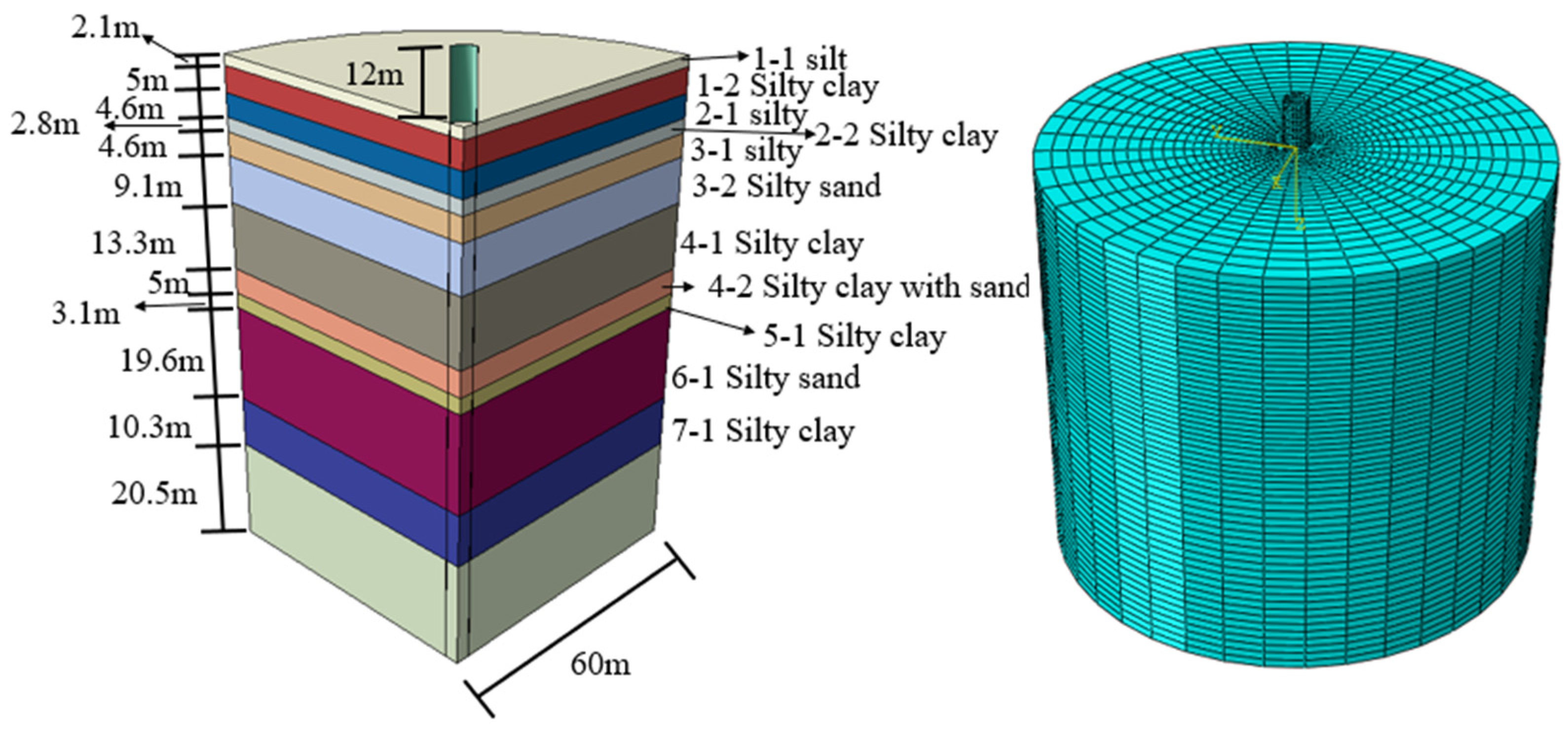
2.1. Finite Element Model Selection
2.2. Effects of Meshing and Interface
2.3. Steps of Model Calculation
2.4. Model Calculation and Loading
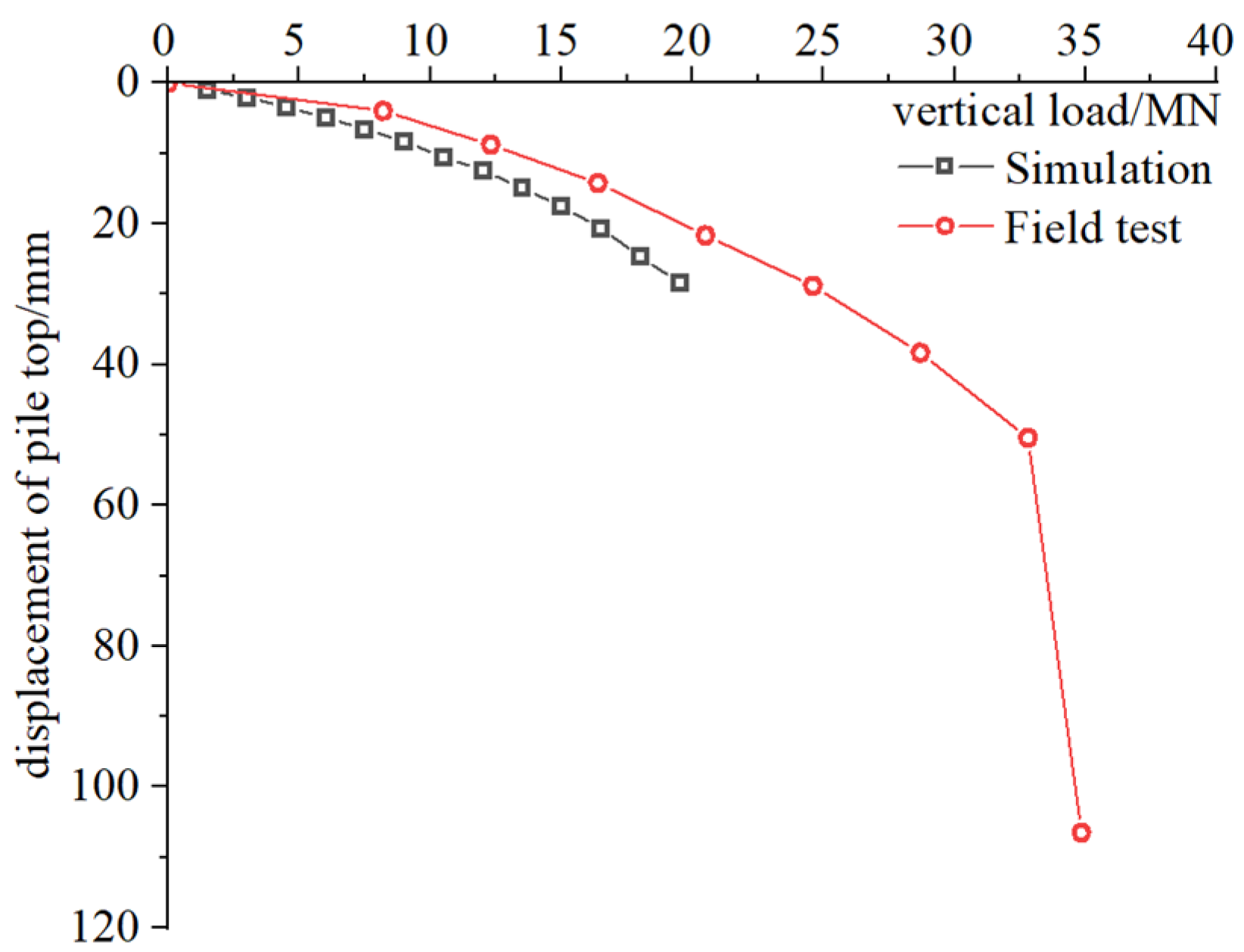
2.5. Simulation Results
3. Influence of Soil Coring on Large Diameter Steel Pipe Pile
3.1. Simulation Condition
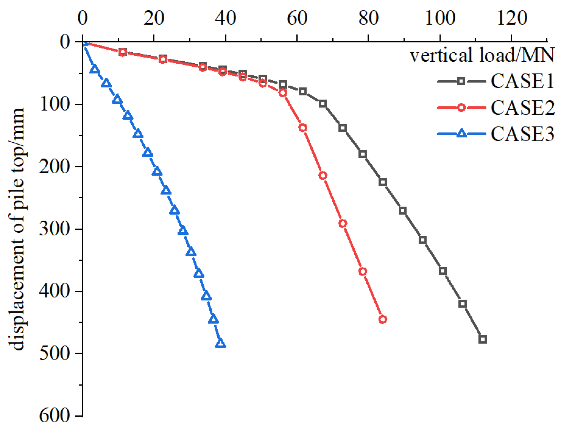
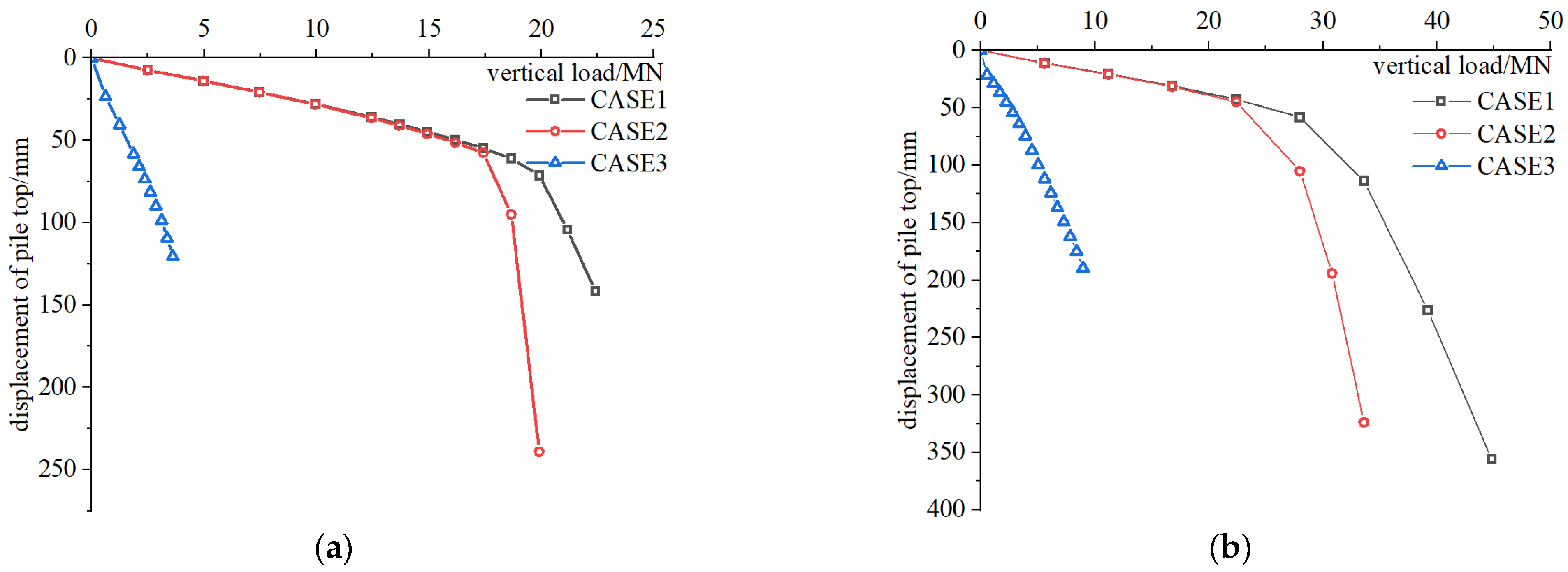
3.2. Result Analysis
4. Formula Correction
5. Engineering Example Verification
5.1. Case Study 1
5.2. Case Study 2
6. Conclusions
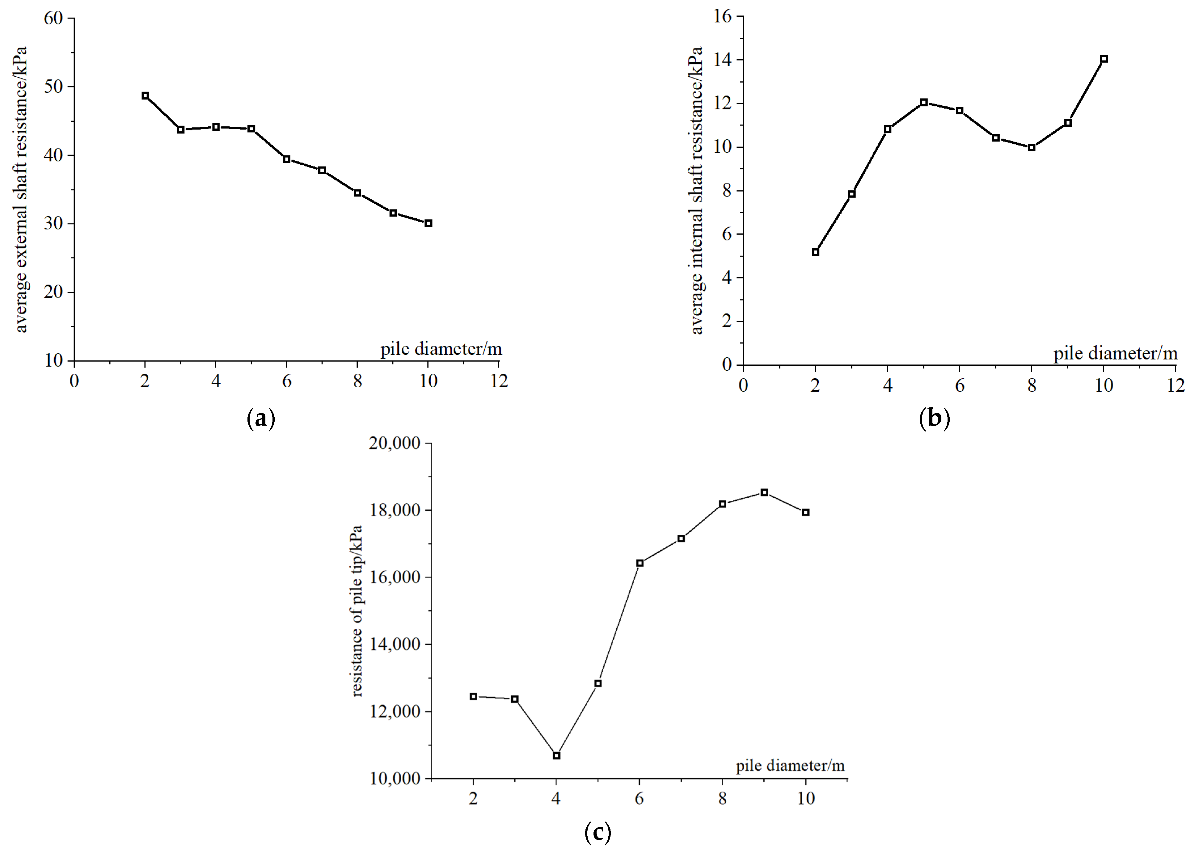
- For the external friction resistance, the pile diameter has a linearly positive effect on it at 2 m < D < 10 m, while it has no influence on it when the diameter is smaller than 2 m or larger than 10 m.
- For pile tip bearing capacity, the correction coefficient β is 2.5 for diameters between 2 m and 4 m, and 3.8 for diameters over 8 m. For diameters from 4 m to 8 m, β varies linearly.
- The calculation methods in the Technical Code for Building Pile Foundations and the Specification for Pile Foundations of Port Engineering are overly conservative. The modified formula provides a more accurate estimate of bearing capacity.
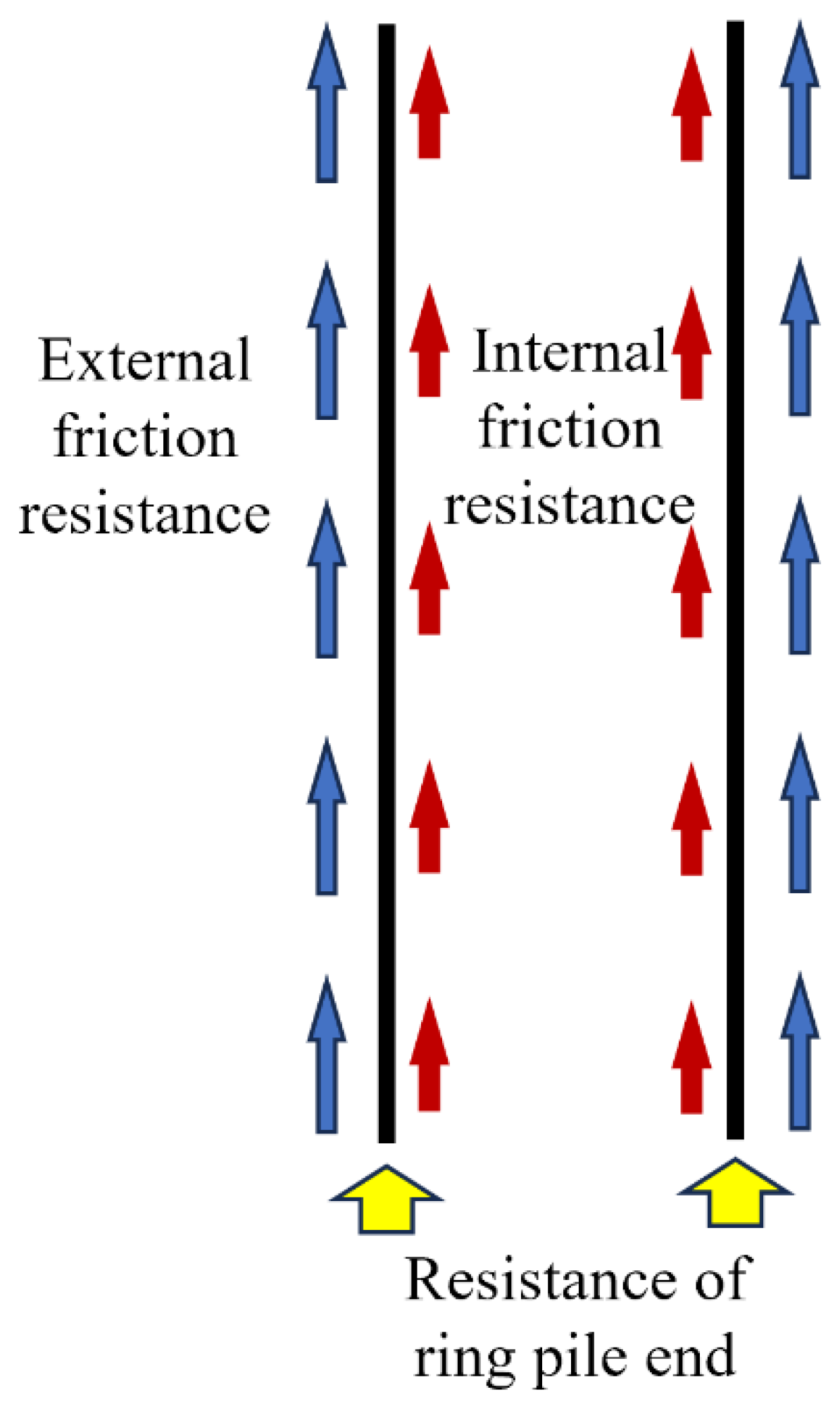
- The friction resistance inside the soil core has a certain influence on the vertical bearing capacity of the steel pipe pile. Through the finite element simulation and field test results, it can be observed that the inner friction resistance of the steel pipe pile does not exceed 30% of the outer friction resistance.
- The effect of soil squeezing during pile driving and the effect of soil compaction around the pile have a great influence on the simulation results, which is also a problem to be considered in subsequent numerical simulation research.
Author Contributions
Funding
Data Availability Statement
Conflicts of Interest
References
- Li, X.; Dai, G.; Zhang, F.; Gong, W. Energy-based analysis of laterally loaded caissons with large diameters under small-strain conditions. Int. J. Geomech. 2022, 22, 05022005. [Google Scholar] [CrossRef]
- Li, X.; Dai, G. Closure to ‘Energy-Based Analysis of Laterally Loaded Caissons with Large Diameters under Small-Strain Conditions’. Int. J. Geomech. 2023, 23, 07023008. [Google Scholar] [CrossRef]
- Li, X.; Dai, G.; Yin, Q.; Yang, X.; Gong, W. A continuum-based model for a laterally loaded steel pipe pile in layered soils in offshore wind farms. Arab. J. Geosci. 2021, 14, 1605. [Google Scholar] [CrossRef]
- Karalar, M.; Dicleli, M. Effect of pile orientation on the fatigue performance of jointless bridge H-piles subjected to cyclic flexural strains. Eng. Struct. 2023, 276, 115385. [Google Scholar] [CrossRef]
- Karalar, M.; Dicleli, M. Effect of thermal induced flexural strain cycles on the low cycle fatigue performance of integral bridge steel H-piles. Eng. Struct. 2016, 124, 388–404. [Google Scholar] [CrossRef]
- Karalar, M.; Dicleli, M. Fatigue in jointless bridge H-piles under axial load and thermal movements. J. Constr. Steel Res. 2018, 147, 504–522. [Google Scholar] [CrossRef]
- Karalar, M.; Dicleli, M. Low-cycle fatigue in steel H-piles of integral bridges; a comparative study of experimental testing and finite element simulation. Steel Compos. Struct. Int. J. 2020, 34, 35–51. [Google Scholar]
- Dicleli, M.; Karalar, M. Optimum characteristic properties of isolators with bilinear force–displacement hysteresis for seismic protection of bridges built on various site soils. Soil Dyn. Earthq. Eng. 2011, 31, 982–995. [Google Scholar] [CrossRef]
- Qin, W.; Cai, S.; Dai, G.; Wang, D.; Chang, K. Soil Resistance during Driving of Offshore Large-Diameter Open-Ended Thin-Wall Pipe Piles Driven into Clay by Impact Hammers. Comput. Geotech. 2023, 153, 105085. [Google Scholar] [CrossRef]
- Li, X.; Zhu, M.; Dai, G.; Wang, L.; Liu, J. Interface Mechanical Behavior of Flexible Piles Under Lateral Loads in OWT Systems. China Ocean Eng. 2023, 37, 484–494. [Google Scholar] [CrossRef]
- Ministry of Housing and Urban-Rural Construction of the People’s Republic of China. JGJ 94-2008 Technical Code for Building Pile Foundation; China Architecture & Building Press: Beijing, China, 2008. [Google Scholar]
- Ministry of Transport of the People’s Republic of China. JTS167-4-2012, Specification for Pile Foundation of Port Engineering; China Communications Press: Beijing, China, 2012. [Google Scholar]
- API. Recommended Practice for Planning, Designing, and Constructing Fixed Offshore Platforms—Working Stress Design, API RP2A-WSD, 21st ed.; American Petrolium Institute: Washington, DC, USA, 2014. [Google Scholar]
- Det Norske Veritas. Design of Offshore Wind Turbine Structures; Offshore Standard DNV-OS-J101; Det Norske Veritas: Oslo, Norway, 2014. [Google Scholar]
- Qin, W.; Dai, G.; Zhao, X.; Shu, G.; Gong, W. Experimental Investigation of CFFP-Soil Interaction in Sand under Cyclic Lateral Loading. Geotech. Test. J. 2019, 42, 1055–1074. [Google Scholar] [CrossRef]
- OuYang, H.; Dai, G.; Qin, W.; Zhang, C.; Gong, W. Dynamic behaviors of calcareous sand under repeated one-dimensional impacts. Soil Dyn. Earthq. Eng. 2021, 150, 106891. [Google Scholar] [CrossRef]
- Stefanoff, G.; Boshinov, B. Bearing capacity of hollow piles driven by vibration. In Proceedings of the 9th International Conference on Soil Mechanics and Foundation Engineering, Tokyo, Japan, 10–15 July 1977; pp. 753–758. [Google Scholar]
- Stevens, R.S.; Wiltsie, E.A.; Turton, T.H. Evaluating Drivability for Hard Clay, Very Dense Sand, and Rock, Offshore Technology Conference. In Proceedings of the Offshore Technology Conference, Houston, TX, USA, 3–6 May 1982. [Google Scholar]
- Gallagher, D.A.; Gavin, K.G. An Investigation of the Effect of Partial Plugging During Installation on the Shaft Capacity of Open-Ended Piles in Soft Clay. In Contemporary Issues in Deep Foundations; American Society of Civil Engineers: Reston, VA, USA, 2007; pp. 1–8. Available online: https://ascelibrary.org/doi/abs/10.1061/40902%28221%2935 (accessed on 21 October 2024).
- Guo, Y.; Yu, X. Soil Plugging Mechanism on Large Diameter Pipe Piles: Insight from Discrete Element Simulations. In Proceedings of the International Foundations Congress and Equipment Expo 2015, San Antonio, TX, USA, 17–21 March 2015; pp. 1075–1086. [Google Scholar]
- Qin, W.; Li, X.; Dai, G.; Hu, P. Analytical Penetration Solutions of Large-Diameter Open-Ended Piles Subjected to Hammering Loads. J. Mar. Sci. Eng. 2022, 10, 885. [Google Scholar] [CrossRef]
- Li, X.; Dai, G.; Gong, W.; Zhao, X. A numerical study into the impact of soil coring on lateral capacity of piles with large diameter. In Proceedings of the 27th International Ocean and Polar Engineering Conference, San Francisco, CA, USA, 25–30 June 2017. ISOPE-I-17-211. [Google Scholar]
- Li, W.; Li, X.; Wang, T.; Yin, Q.; Zhu, M. The Simplified Method of Head Stiffness Considering Semi-Rigid Behaviors of Deep Foundations in OWT Systems. Buildings 2024, 14, 1803. [Google Scholar] [CrossRef]
- Li, P.; Xia, Y.; Xie, X.; Wang, J.; Wang, C.; Shi, M.; Wang, B.; Wu, H. Study on Vertical Bearing Capacity of Pile Foundation with Distributed Geopolymer Post-Grouting on Pile Side. Materials 2024, 17, 398. [Google Scholar] [CrossRef] [PubMed]
- Zhu, M.X.; Lu, H.Q.; Dai, G.L.; Wan, Z.H. Effect of Vertical Shaft Resistance on the Lateral Behavior of Large-Diameter Pile Foundation. In Proceedings of the China-Europe Conference on Geotechnical Engineering, Vienna, Austria, 13–16 August 2016; Springer International Publishing: Cham, Switzerland, 2018; Volume 2. [Google Scholar]
- Fleming, W.G.K.; Weltman, A.J.; Randolph, M.F.; Elson, W.K. Piling Engineering, Glasgow and London; Surrey University Press: Glascow, UK, 1992. [Google Scholar]
- Xu, G.; Zhang, W. A study of size effect and boundary effect in centrifugal tests. Chin. J. Geotech. Eng. 1996, 18, 80–85. (In Chinese) [Google Scholar]
- Zhang, M.; Li, S.; Peng, W.; Song, H. Simulation of vertical bearing features for large-diameter and super-long steel pipe pile based on FLAC3D. Rock Soil Mech. 2011, 32, 2856–2860. [Google Scholar]
- Su, H.; Li, J.; Wen, Z.; Zhou, F. A bi-criteria combined evaluation approach for reinforcement effect of gravity dam with cracks. Int. J. Solids Struct. 2018, 147, 238–253. [Google Scholar] [CrossRef]
- Pan, D.; Lucarelli, A.; Cheng, Z. Field test of monopile for offshore wind turbine foundations. In Proceedings of the Geotechnical and Structural Engineering Congress, Phoenix, AZ, USA, 14–17 February 2016. [Google Scholar]


| Main Reference | Research Object | Main Conclusion |
|---|---|---|
| Stefanoff (1977) [17] | Soil plug effect | Pile tip resistance increases exponentially with the ratio of soil plug length to pile diameter. |
| Stevens (1982) [18] | Soil plug effect | The plugging rate’s effect on vertical bearing capacity in both cohesive and cohesionless soil conditions. |
| Gallagher (2007) [19] | Soil plug effect | Determined that the soil plugging effect on bearing capacity was minimal. |
| Guo (2015) [20] | Soil plug effect | The influence of soil race in the process of large-diameter pile penetration was determined by discrete element simulation. |
| Qin (2022) and Li (2017), (2024) [21,22,23] | Soil plug effect | It is determined that the soil inside the pile has influence on the lateral bearing capacity of the foundation. |
| Li (2024) [24] | Soil plug effect | Influence of distributed grouting on bearing capacity |
| Zhu (2018) [25] | Size effect | Presents a numerical solution for the resisting moment that is suitable for any type of side friction model. |
| Diameter (m) | Wall Thickness (mm) | Length of Pile (m) | Embedment Length (m) | Elastic Modulus (kPa) | Poisson’s Ratio | Constitutive Model |
|---|---|---|---|---|---|---|
| 6 | 60 | 67 | 55 | 2.1 × 10⁸ | 0.3 | Ideal elastic |
| Layers No. | Soil Layer Properties | Layers Thickness (m) | Soil Density kg/m3 | Compression Modulus MPa | Poisson’s Ratio | Internal Friction Angle (°) | Cohesion (kPa) |
|---|---|---|---|---|---|---|---|
| 1-1 | silt | 2.1 | 1825 | 9.26 | 0.25 | 24 | 11 |
| 1-2 | silty clay | 5.0 | 1490 | 2.54 | 0.30 | 11.4 | 19 |
| 2-1 | silt | 4.6 | 1820 | 10.55 | 0.25 | 25 | 9 |
| 2-2 | silty clay | 2.8 | 1735 | 5.08 | 0.29 | 19.4 | 38.3 |
| 3-1 | silt | 4.6 | 1815 | 9.38 | 0.25 | 26 | 10 |
| 3-2 | silty sand | 9.1 | 1735 | 13.51 | 0.28 | 15.3 | 27 |
| 4-1 | silty clay | 13.3 | 1590 | 5.71 | 0.28 | 12.9 | 26.8 |
| 4-2 | silty clay with sand | 5.0 | 1785 | 9.61 | 0.23 | 32.5 | 50.0 |
| 5-1 | silty clay | 3.1 | 1715 | 3.44 | 0.28 | 15.9 | 40.5 |
| 6-1 | silty sand | 19.6 | 1810 | 11.16 | 0.23 | 35 | 8.0 |
| 7-1 | silty clay | 10.3 | 1805 | 8.83 | 0.26 | 18.1 | 65 |
| CASE No. | Simulated Bearing Capacity (kN) | Composition of Bearing Capacity |
|---|---|---|
| CASE 1 | 71,171 | Qtotal = Qf + Qi + Qb |
| CASE 2 | 59,309 | Qf + Qb |
| CASE 3 | 30,253 | Qi + Qb |
| Diameter (m) | Wall Thickness (cm) | Area of Pile End (m2) | Length of Pile (m) | Embedment Depth (m) | Elastic Modulus (kPa) | Poisson’s Ratio | Constitutive Model |
|---|---|---|---|---|---|---|---|
| 2 | 2 | 0.124 | 67 | 55 | 2.1 × 10⁸ | 0.3 | Ideal elastic |
| 3 | 3 | 0.280 | |||||
| 4 | 4 | 0.498 | |||||
| 5 | 5 | 0.778 | |||||
| 7 | 7 | 1.524 | |||||
| 8 | 8 | 1.991 | |||||
| 9 | 9 | 2.519 | |||||
| 10 | 10 | 3.110 |
| Diameter (m) | Percentage of Qfm (%) | Percentage of Qim (%) | Percentage of Qbm (%) | Weight of Piles (kN) | Bearing Capacity (kN) | |||
|---|---|---|---|---|---|---|---|---|
| Qf | Qi | Qb | Q | |||||
| 2 | 83.59 | 8.72 | 7.69 | 641 | 16,836 | 1756 | 1549 | 20,141 |
| 3 | 75.26 | 13.24 | 11.50 | 1443 | 22,686 | 3991 | 3466 | 30,143 |
| 4 | 70.69 | 17.00 | 12.32 | 2565 | 30,513 | 7336 | 5316 | 43,165 |
| 5 | 65.25 | 17.56 | 17.19 | 4008 | 37,915 | 10,204 | 9989 | 58,108 |
| 6 | 57.49 | 16.67 | 25.84 | 5771 | 40,918 | 11,862 | 18,391 | 71,171 |
| 7 | 54.32 | 14.66 | 31.02 | 7855 | 45,767 | 12,352 | 26,137 | 84,256 |
| 8 | 48.97 | 13.88 | 37.16 | 10,260 | 47,724 | 13,524 | 36,212 | 97,460 |
| 9 | 43.59 | 15.03 | 41.38 | 12,985 | 49,160 | 16,952 | 46,674 | 112,786 |
| 10 | 39.53 | 18.08 | 42.39 | 16,031 | 52,037 | 23,798 | 55,795 | 131,630 |
| Pile Number | Diameter (m) | Wall Thickness (mm) | Embedment Depth (m) | Pile Top Elevation (m) | Pile Tip Elevation (m) |
|---|---|---|---|---|---|
| S1 | 2.8 | 40 | 72.5 | 8.2 | −85.5 |
| S2 | 2.8 | 40 | 72.5 | 8.2 | −85.5 |
| Pile No. | S1 and S2 | |||||
|---|---|---|---|---|---|---|
| Top elevation of soil layer (m) | −13.5 | −27.7 | −31.2 | −61.5 | −73.5 | Total (kN) |
| bottom elevation of soil layer (m) | −27.7 | −31.2 | −61.5 | −73.5 | −85.5 | |
| Soil Thickness (m) | 14.2 | 3.5 | 30.3 | 12 | 12 | |
| Soil layer properties | Silty clay | Silty clay | Silty sand | fine sand | fine sand | |
| Characteristic value of bearing capacity of foundation fak (kPa) | 80 | 110 | 180 | 230 | 260 | |
| Standard value of ultimate lateral resistance qsik (kPa) | 15 | 45 | 60 | 70 | 80 | |
| Standard value of end face resistance qpk (kPa) | —— | —— | 4000 | 5000 | 6000 | |
| Measured side friction (kPa) | 22 | 56 | 72 | 101 | 121 | |
| Measured friction friction qsiA (kN) | 2747 | 1723 | 19,181 | 10,656 | 12,766 | 47,073 |
| friction resistance of each layer qsikA (kN) | 1873 | 1385 | 15,984 | 7385 | 8440 | 35,067 |
| Calculation Details for Compared Piles | S1 | S2 | |
|---|---|---|---|
| Measured end resistance (kN) | 2819 | 2823 | |
| Coefficient of soil plug effect at pile tip, λp | 0.686 | 0.686 | |
| Standard value of ultimate end resistance (kPa) | 6000 | 6000 | |
| Ultimate end resistance (kN) | by Standard of the design of building foundation | 9047 | 9047 |
| by Specification for pile foundation of Port Engineering | 3297 | 3297 | |
| by modified formula | 5200 | 5200 | |
| Total bearing capacity (kN) | by in-situ measured | 49,891 | 49,891 |
| by Standard of the design of building foundation | 44,114 | 44,114 | |
| by Specification for pile foundation of Port Engineering | 38,364 | 38,364 | |
| by modified formula | 46,228 | 46,228 | |
| Pile Number | Diameter (m) | Wall Thickness (mm) | Embedment Depth (m) | Pile Top Elevation (m) | Pile Tip Elevation (m) |
|---|---|---|---|---|---|
| S3 | 2.0 | 50 | 71.5 | −10.1 | −64.0 |
| S4 | 2.0 | 50 | 77.5 | −10.5 | −70.0 |
| Pile No. | Soil Thickness (m) | Soil Layer Properties | Characteristic Value of Foundation Bearing Capacity fak (kPa) | Standard Value of Side Resistance qsik (kPa) | Standard Value of End Resistance qpk (kPa) | Measured Side Resistance (kPa) | Measured Resistance of Each Layer qsiA (kN) | Calculated Resistance of Each Layer qsikA (kN) |
|---|---|---|---|---|---|---|---|---|
| S3 | 2.62 | mud | 40 | 12 | —— | 23 | 378 | 197 |
| 7.90 | Silty clay | 50 | 18 | —— | 54 | 2679 | 893 | |
| 3.00 | Silty sand | 150 | 50 | —— | 67 | 1262 | 942 | |
| 8.20 | Silty sand | 200 | 65 | —— | 107 | 5510 | 3347 | |
| 9.80 | Silty clay | 70 | 48 | —— | 105 | 6462 | 2954 | |
| 16.30 | Silty clay | 80 | 50 | —— | 94 | 9622 | 5118 | |
| 1.70 | Silty clay | 180 | 65 | 3600 | 95 | 1014 | 694 | |
| 4.08 | Fine sand | 260 | 80 | 5600 | 128 | 3280 | 2050 | |
| S4 | 1.37 | Silty sand | 100 | 32 | —— | 32 | 275 | 275 |
| 7.9 | Silty clay | 50 | 16 | —— | 40 | 1984 | 794 | |
| 3.3 | Silty sand | 150 | 50 | —— | 63 | 1306 | 1036 | |
| 7 | Silty sand | 200 | 65 | —— | 77 | 3385 | 2857 | |
| 10.1 | Silty clay | 70 | 48 | —— | 80 | 5074 | 3045 | |
| 12 | Silty sand | 220 | 70 | 4800 | 103 | 7762 | 5275 | |
| 4.6 | Silty clay | 180 | 65 | 3600 | 111 | 3207 | 1878 | |
| 7.4 | Silty sand | 260 | 80 | 4500 | 135 | 6274 | 3718 | |
| 1.9 | Silty clay | 180 | 65 | 3600 | 97 | 1157 | 776 | |
| 3.93 | Silt | 260 | 70 | 4500 | 114 | 2814 | 1728 |
| Calculation Details for Compared Piles | S3 | S4 | |
|---|---|---|---|
| Measured end resistance (kN) | 1724 | 1590 | |
| Coefficient of soil plug effect at pile tip, λp | 0.326 | 0.314 | |
| Standard value of ultimate resistance (kPa) | 5600 | 4500 | |
| ultimate end resistance (kN) | by Design code for building foundation | 2306 | 2221 |
| by Specification for pile foundation of Port Engineering | 1766 | 1766 | |
| by modified formula | 4286 | 3444 | |
| Total bearing capacity (kN) | by in-situ measured | 31,392 | 34,828 |
| by Design code for building foundation | 21,206 | 23,602 | |
| by Specification for pile foundation of Port Engineering | 17,962 | 23,147 | |
| by modified formula | 22,749 | 27,968 | |
Disclaimer/Publisher’s Note: The statements, opinions and data contained in all publications are solely those of the individual author(s) and contributor(s) and not of MDPI and/or the editor(s). MDPI and/or the editor(s) disclaim responsibility for any injury to people or property resulting from any ideas, methods, instructions or products referred to in the content. |
© 2024 by the authors. Licensee MDPI, Basel, Switzerland. This article is an open access article distributed under the terms and conditions of the Creative Commons Attribution (CC BY) license (https://creativecommons.org/licenses/by/4.0/).
Share and Cite
Shu, J.; Gu, X.; Wang, T.; Li, X.; Zhu, M. Influence of the Internal Friction Resistance on the Vertical Compressive Bearing Capacity of Large-Diameter Steel Pipe Piles. Buildings 2024, 14, 3481. https://doi.org/10.3390/buildings14113481
Shu J, Gu X, Wang T, Li X, Zhu M. Influence of the Internal Friction Resistance on the Vertical Compressive Bearing Capacity of Large-Diameter Steel Pipe Piles. Buildings. 2024; 14(11):3481. https://doi.org/10.3390/buildings14113481
Chicago/Turabian StyleShu, Jiaqing, Xiaoqing Gu, Tengfei Wang, Xiaojuan Li, and Mingxing Zhu. 2024. "Influence of the Internal Friction Resistance on the Vertical Compressive Bearing Capacity of Large-Diameter Steel Pipe Piles" Buildings 14, no. 11: 3481. https://doi.org/10.3390/buildings14113481
APA StyleShu, J., Gu, X., Wang, T., Li, X., & Zhu, M. (2024). Influence of the Internal Friction Resistance on the Vertical Compressive Bearing Capacity of Large-Diameter Steel Pipe Piles. Buildings, 14(11), 3481. https://doi.org/10.3390/buildings14113481