Article

Research on Coordinated Relationship Between Deformation and Force in Shaft Foundation Pit Support Structures

1
Department of Civil Engineering, Xi’an Jiaotong University, Xi’an 710049, China
2
China Jikan Research Institute of Engineering Investigations and Design, Co., Ltd., Xi’an 710043, China
3
School of Civil Engineering, Central South University, Changsha 410075, China
*
Author to whom correspondence should be addressed.
Buildings 2024, 14(11), 3438; https://doi.org/10.3390/buildings14113438
Submission received: 13 October 2024 / Revised: 27 October 2024 / Accepted: 28 October 2024 / Published: 29 October 2024
(This article belongs to the Section Building Structures)

Abstract

In order to investigate the coordinated relationship between lateral deformation of the diaphragm wall and axial force of the internal strut, this paper first carried out a scaled model test on the mechanical features of a foundation pit support system based on a novel axial force servo device. Then, a finite element model was established to simulate the scaled model test, and the correctness of the finite element modeling approach was validated by comparing test results. After that, the same finite element modeling method was used to analyze the coordinated relationship between axial force and lateral deformation in the prototype foundation pit support structure. The results show that the axial force of the inner strut is negatively correlated with the lateral deformation in the diaphragm wall. The initial maximum lateral deformation in the diaphragm wall of the shaft foundation pit occurs at the bottom of the foundation pit, so changing the length of bottom strut simultaneously is the most effective way to adjust the mechanical behavior of the support structure. Under various support conditions, the maximum lateral deformation of the diaphragm wall in the prototype project is 0.59~0.66‰ of the total excavation depth of the foundation pit, and the maximum axial force of internal support is 11~30% of the yield load of a single steel strut.

1. Introduction

With the utilization of urban underground space, excavation projects for foundation pits have become an indispensable part of urban infrastructure construction [1,2,3]. Excavation in congested urban space requires a very strong support system for the foundation pit, otherwise soil loosening around the pit will adversely affect the service safety of the adjacent buildings [4,5,6,7,8], and even lead to disastrous collapse accidents [9,10,11].
In the conventional design of foundation pit support systems, the influence of foundation pit excavation on the surrounding soil is usually suppressed only by controlling the lateral displacement of support structures [12,13,14]. This design method, while strictly controlling the lateral displacement [15,16], often increases the axial force of internal horizontal support and brings higher requirements for the construction and cost of internal horizontal support [17,18,19]. Once the support axial force is too large, the internal horizontal support will face the risk of failure [20]. On the other hand, before the completion of the internal horizontal support’s construction, surrounding support structures such as the diaphragm wall and occlusal pile are in an unsupported state [21,22], which leads to a discrepancy between the actual and design value of the lateral displacement of the diaphragm wall and the occlusal pile after construction is completed [23]. When the difference exists, the traditional passively stressed support system cannot be effectively adjusted, which poses safety hazards for the subsequent construction and service of the foundation pit [24].
Therefore, scholars have proposed various active adjustment methods for internal support based on axial force servo devices. Wang et al. [25] arranged servo jacks at the contact position between concrete inner struts and the diaphragm wall, realized the change in support axial force through servo jack, and achieved preliminary application in an actual project. However, the resulting jacks and concrete struts are completely separated, and the internal support has no integrity. To overcome this drawback, Di et al. [26,27] used steel struts instead of concrete struts and bolted the jack to the end of the steel strut so that the internal support could maintain good integrity. In the same manner, Li et al. [28] and Xiao et al. [29] studied the influence of active adjustment of internal support axial force on the mechanical behavior of diaphragm wall support systems in practical engineering through bolted jacks and steel struts. In addition, in terms of the novel internal support adjustment device, Chen et al. [30] combined a symmetrical bolt-fastened wedge joint and purlins to actively control the lateral deformation in the diaphragm wall, and a scaled model test was carried out to validate the effectiveness of the device. Jin [31] and Di [32] used screws and nuts that can be rotated to change the length of internal strut in a scaled model experiment.
Previous studies only focused on the effect of unidirectional support axial force adjustment on the mechanical behaviors of foundation pit support structures. There is a huge research gap regarding bidirectional axial force adjustment devices and the coordination relationship between force and deformation in foundation pit support structures.
The purpose of this paper is to investigate the coordinated relationship between the axial force of the inner strut and lateral deformation in the diaphragm wall in a bidirectional support foundation pit. Firstly, a scaled model of a shaft foundation pit and its support structure was manufactured based on novel support axial force servo equipment and an active bidirectional internal strut adjustment approach. Then, the finite element method was used to simulate a scaled model test with the purpose of verifying the correctness of the finite element modeling approach by comparing calculated results with test results under various test conditions. Finally, for the prototype project, the same method was used to establish the finite element model for the excavation of shaft foundation pit and the mechanical analysis of support structures, and different support schemes under active adjustments of internal support were compared.

2. Scaled Model Test Design

In order to investigate the coordinated relationship between the axial force of the internal support and lateral deformation in the diaphragm wall of the prototype integrated utility tunnel shaft, a scaled model test of the shaft foundation pit and its support system was designed and carried out firstly to test the influence pattern of active adjustment of bidirectional internal support on the axial force of the internal strut and deformation in the diaphragm wall.

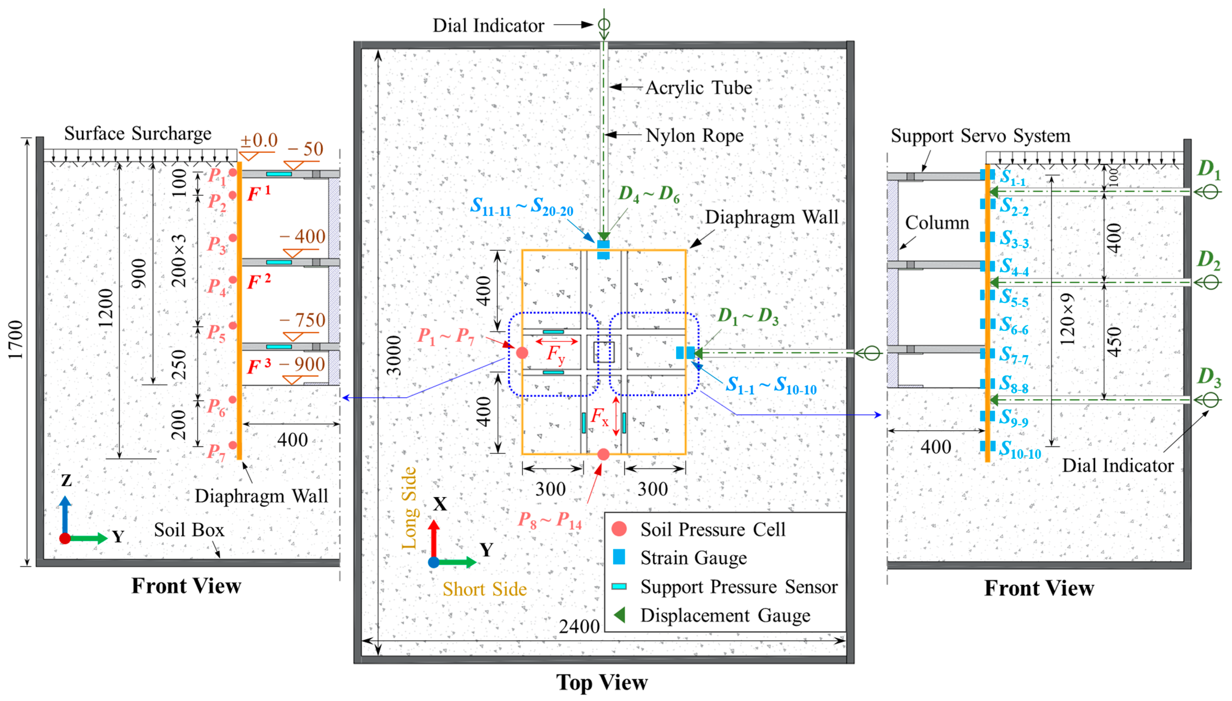
2.1. Model Test Components

Figure 1 shows the main components of the scaled model of the shaft foundation pit and its support structure. The dimensions of the pit and support structure were designed on the basis of a prototype foundation pit with 1:25 scaling, as listed in Table 1. On this basis, a soil box with dimensions of 3000 mm × 2400 mm × 1700 mm and a diaphragm wall with dimensions of 1000 mm × 800 mm × 1200 mm were manufactured. For the convenience of experimental measurement, acrylic plates [33] with a low elastic modulus were used for the diaphragm wall.
The bidirectional horizontal internal struts were set up on holes pre-drilled holes in the support column to provide horizontal support for the diaphragm wall. The height of the pre-drilled holes varied to change the position of the inner strut. In order to realize the active adjustment of the bidirectional horizontal support, a novel support axial force servo device was designed and adopted, which activated the internal electrical motor of the horizontal strut and controlled the rotation of the transmission screw through an external control panel, and then pushed the screw support forward and backward, achieving the elongation and shortening of the strut. In addition, a pressure sensor was placed at the end of the screw support to measure the axial force of the internal strut.

2.2. Test Schemes and Test Conditions

The force and deformation features of the diaphragm wall were measured by placing the soil pressure cell, strain gauge, and displacement gauge on the surface of the diaphragm wall. Due to the symmetry of support structure, the soil pressure cell and the strain gauge were arranged separately, and the dial indicator was installed outside the soil box and connected to the displacement measuring point of the diaphragm wall through an inelastic nylon rope, as shown in Figure 2.
In the scaled model test, the trial soil was first backfilled to a height of 0.4 m; then, the diaphragm wall and inner support were positioned and erected, followed by backfilling the trial soil to a height of 1.6 m. The initial forces and deformations of the support structure were measured after the soil surface was leveled. After that, various test conditions were established by changing the weight of the sandbags stacked at the top of the soil around the pit and the height of the bidirectional internal strut, as listed in Table 2. The support heights of the inner struts were designed according to the [34], as shown in Figure 3.

3. Numerical Investigations

A numerical simulation of the above shaft foundation pit model test was carried out and the correctness of the finite element model was verified by comparing the mechanical behaviors of the support structure under different test conditions.

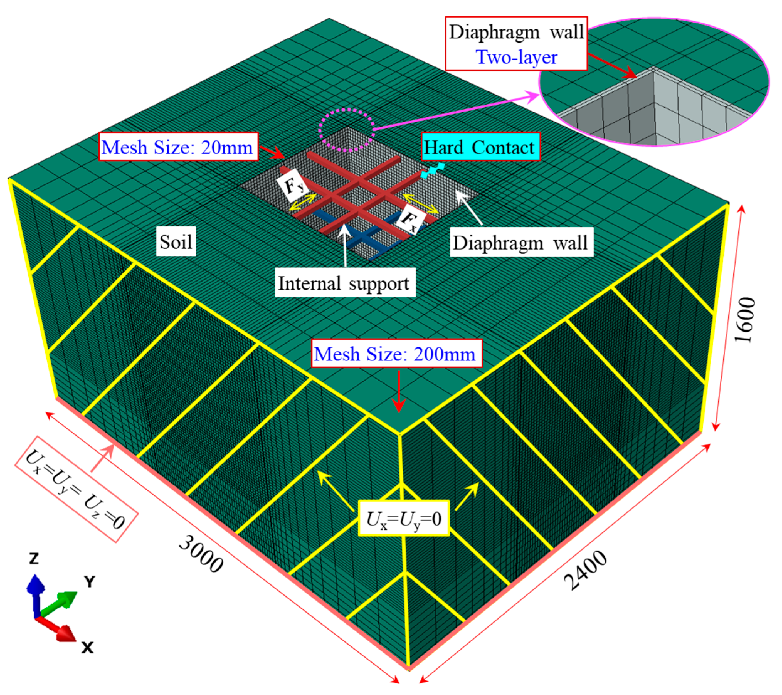
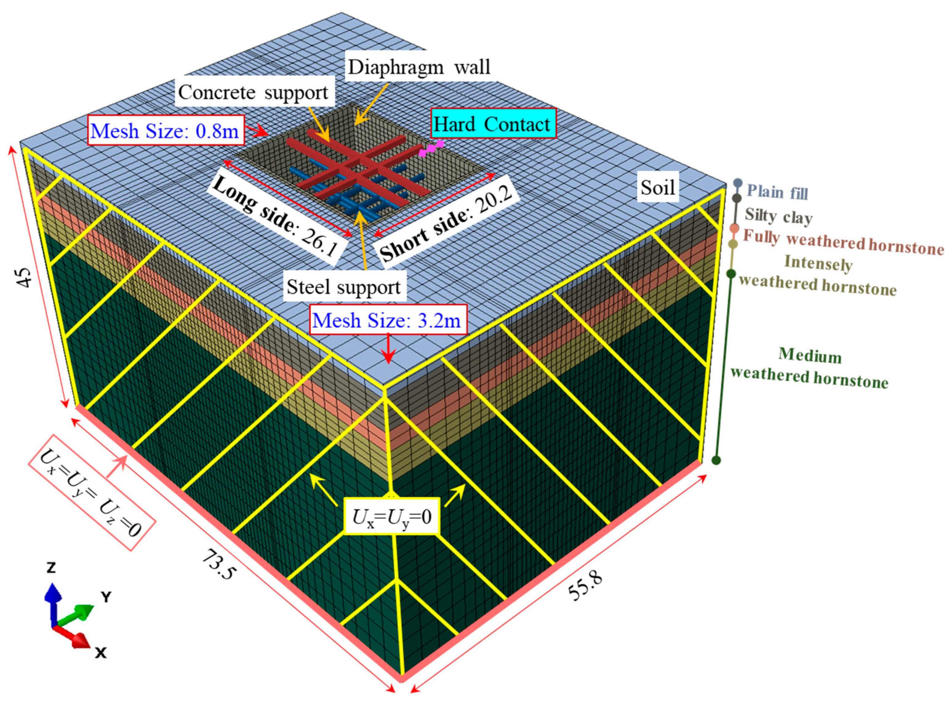
3.1. Numerical Model

In the finite element model (FEM), the trial soil and diaphragm wall were modeled using a three-dimensional solid mesh (C3D8R), and internal horizontal supports were modeled using a beam element mesh (B31). The Mohr–Coulomb constitutive model [35,36] was used for trial soil material; only elastic deformation was considered for both the diaphragm wall and the internal horizontal supports. The mechanical properties of the trial soil sample were measured by confined compression test and direct shear test, as listed in Table 3.
The finite element model of foundation pit scaled model test is displayed in Figure 4. The finite element model constrained the displacement degrees of freedom of the trial soil at the bottom in three directions and constrained the displacement degrees of freedom of the side surfaces along both x and y directions to simulate the constraint effect of the soil box on the trial soil. “Hard contact” was used for the normal contact between diaphragm wall and trial soil and between internal horizontal struts and diaphragm wall. In addition, a penalty friction coefficient of 0.2 was applied to the tangential contact between diaphragm wall and trial soil. Before calculating the deformation and internal force of the support structure, geostatic stress was applied to the trial soil to simulate its equilibrium state under its own stacking condition. Since the mesh size of the area near the foundation pit excavation has a great influence on calculation results, while the mesh quality of the edge area away from the foundation pit had a little impact on calculation results, the mesh around the foundation pit was encrypted to improve calculation efficiency. For finite element model validation, four test conditions, listed in Table 2, were calculated.

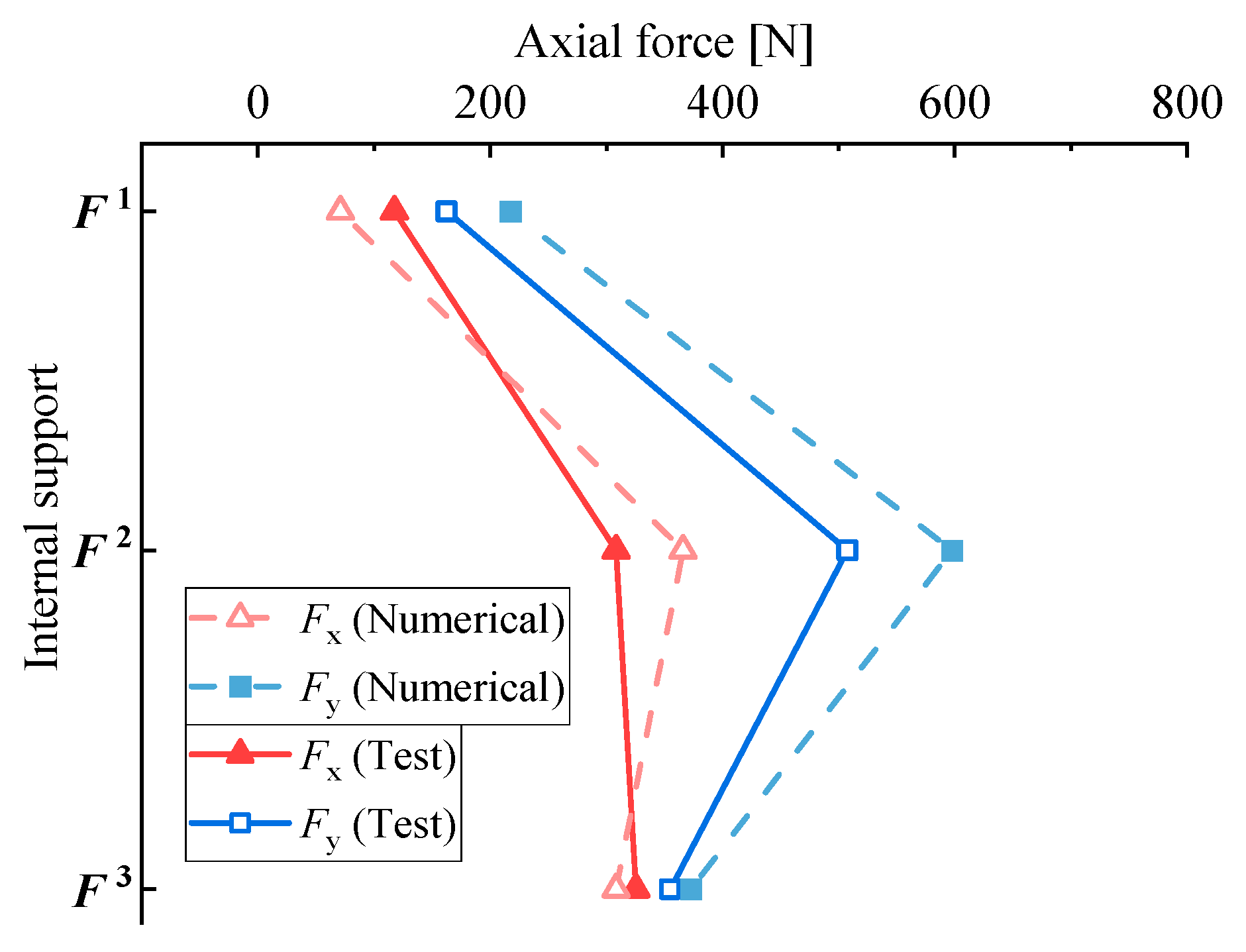
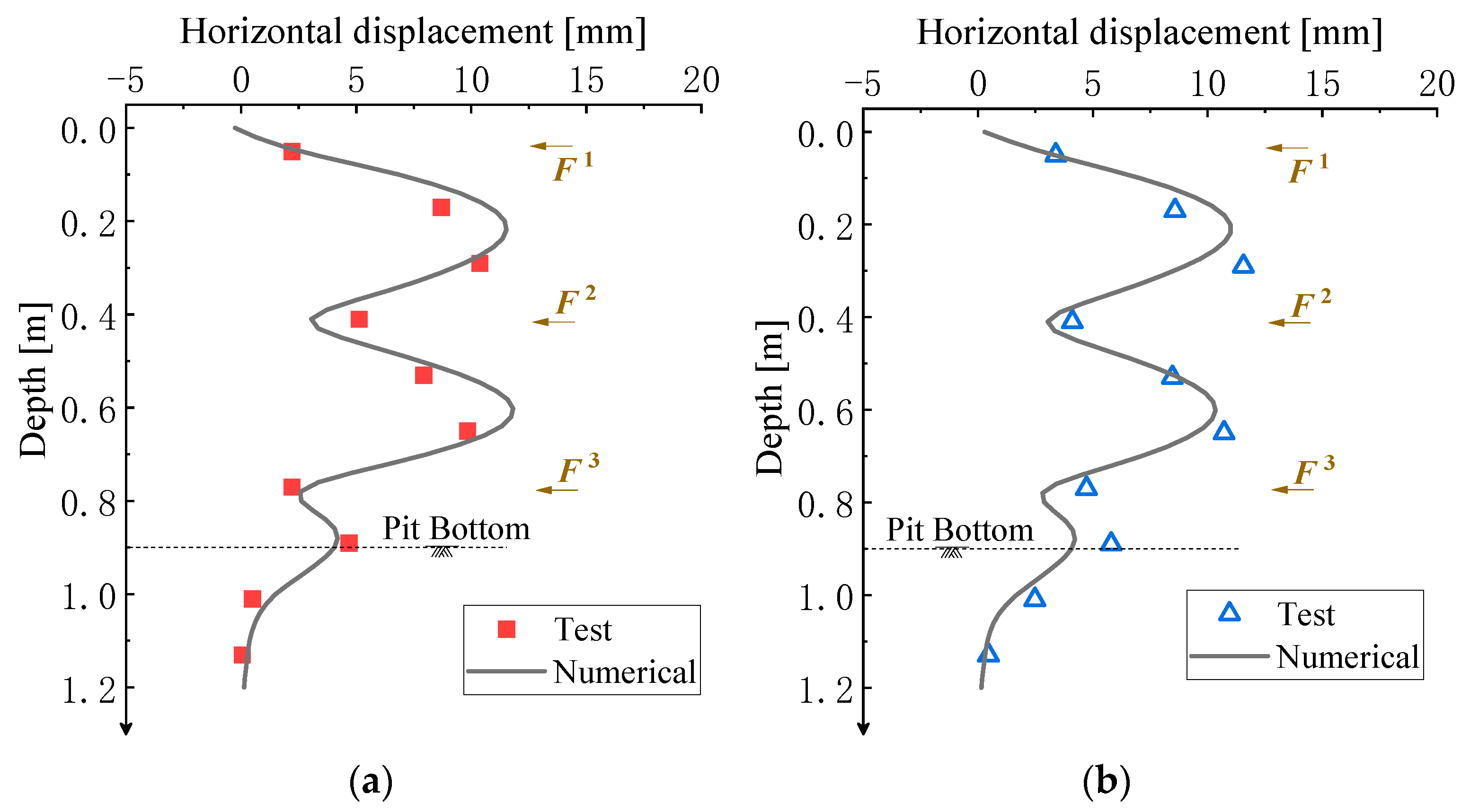
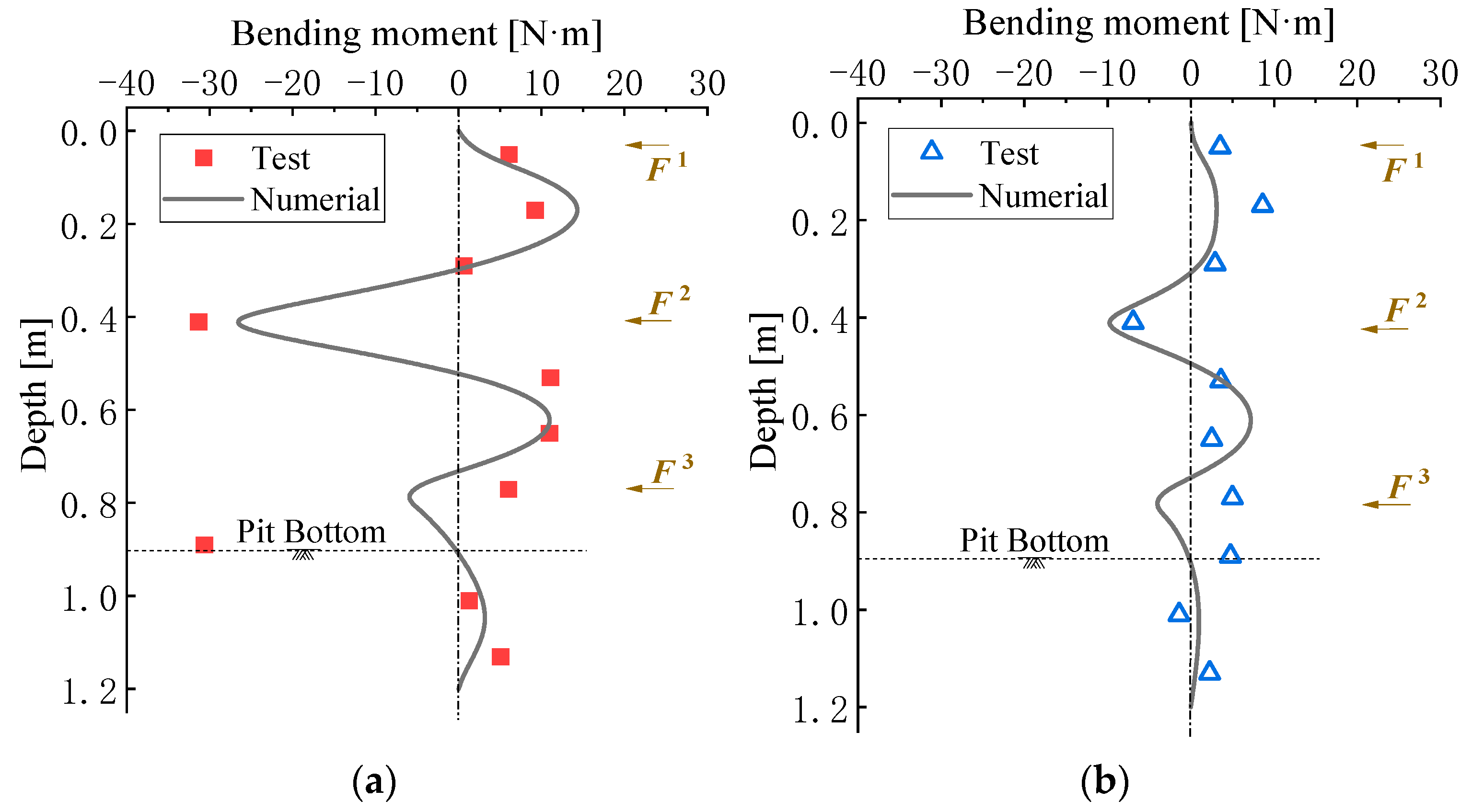
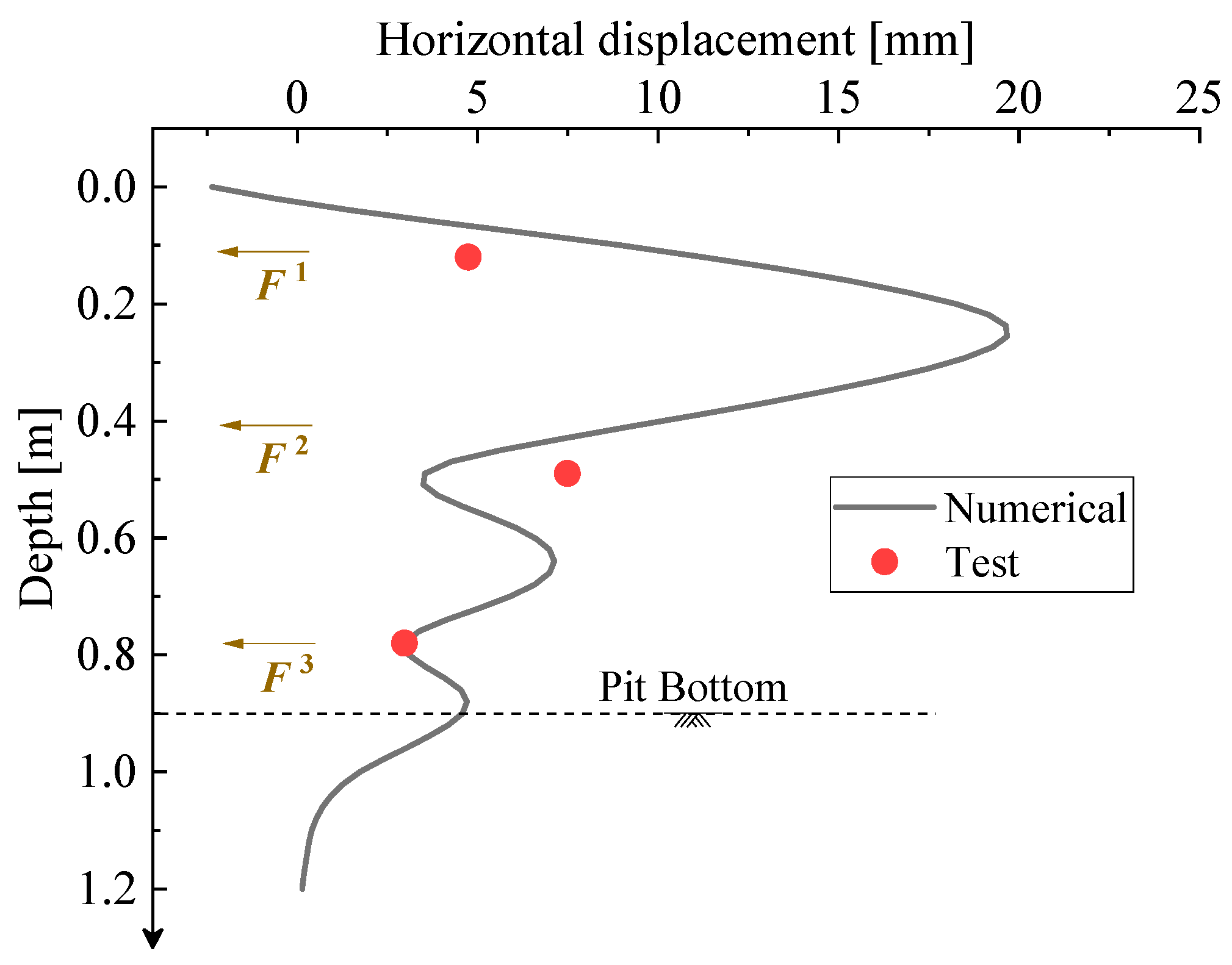
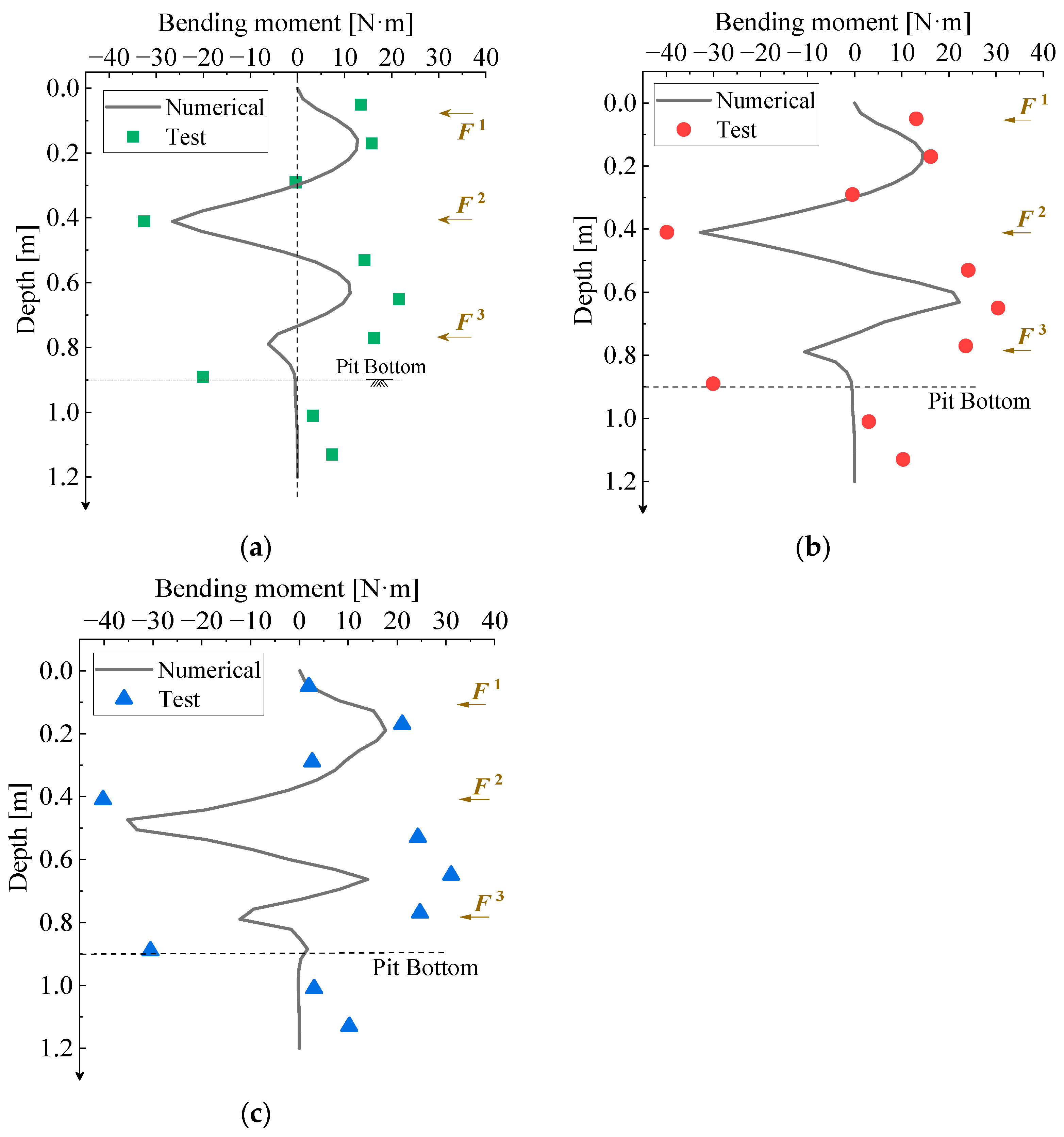
3.2. Calculation Result Validation

Firstly, the results of support forces and deformations in the diaphragm wall without surface surcharge (A0 condition) were compared. Figure 5 shows the comparison curves between the FEM calculation results of the internal support forces and the model test results. For condition A0, the height of inner support F1 is close to the top of the pit, while support F3 is near the bottom of the pit, so the distribution of internal support axial force along the depth direction causes the axial force of F1 to be the smallest, and the axial force of F3 to be smaller than that of F2. Moreover, the support axial forces on the long side of the diaphragm wall (Fy) are all greater than those on the short side (Fx), and the support axial force on the long side of the diaphragm wall at the depth of F2 is about 1.65 times that of the short side. The calculated results of the support axial forces had the same distribution trend with test results along the depth direction; the calculated value of axial force of each support was very close to the test value, with a relative error range of 5.07~68.09%.
Figure 6 compares the calculated results and experimental results of horizontal displacement at the midpoints of the long side and short side of the diaphragm wall. Along the depth direction, due to the effect of the internal support, there are significant fluctuating variations in the lateral displacements of the long and short sides of the diaphragm wall, with the most significant changes occurring near the middle of the foundation pit. The calculated values of horizontal displacement of the diaphragm wall agreed with the test values. The calculated curves showed the maximum value of horizontal displacement of long side was 11.84 mm, which occurred at a depth of 0.61 m, and the maximum value of horizontal displacement of the short side was 11.00 mm, which occurred at a depth of 0.21 m.
Figure 7 illustrates the calculated values of bending moments at the midpoints of the long side and short side of the diaphragm wall. Along the depth direction, with the same distribution pattern of lateral displacement in the diaphragm wall, the bending moments of the diaphragm wall show obvious fluctuating changes of alternating positive and negative moments. The calculated results were consistent with the experimental bending moments, and there were inflection points at the supports. The fluctuation variation in bending moment on the long side of the diaphragm wall is more prominent, with a fluctuation range of about 2.41 times that of the bending moment on the short side of the diaphragm wall.
In summary, it can be seen that the calculation results of internal support forces and deformations in the support structure without surface surcharge were in good agreement with the experimental values.
Then, the calculated results of the internal support forces and deformations in the support structure under various surface surcharge conditions and support conditions were compared with the experimental values. From the above analysis, it can be seen that the support forces and deformations on the long side and short side of the support structure had the same characteristics, and the change degree in long side was more pronounced. Hence, the subsequent comparative study was carried out only for the support force and deformation characteristics of the long side of the diaphragm wall.
Figure 8 compared the calculated and experimental results of internal support axial forces under different test conditions. For conditions A0, A3, and A5, the height of inner support does not change, only the surface surcharge varies, so axial forces of all three supports increase continuously with the increase in surface surcharge, whereas in condition E5, the height of support F1 is reduced so that it is closer to the middle of the foundation pit, the axial force of support F1 is significantly increased, and the axial forces of supports F2 and F3 are reduced accordingly. The calculated support axial force values were very close to the experimental results: the relative error ranges of axial forces in support F1, F2, and F3 were 7.56~11.72%, 2.48~12.82%, and 0.73~7.37%, respectively.
Figure 9 depicts the distribution pattern of horizontal displacements at midpoints of the long side of the diaphragm wall under test condition E5. Along the depth direction, the horizontal displacement of the diaphragm wall fluctuates and changes around the location of internal support, with the most obvious fluctuation in the middle of two support ranges F1 and F2. The displacement values measured at the three displacement measurement points were located on the distribution path of the FEM-calculated curve. From top to bottom, the relative errors of displacement values at the three displacement measurement points were 54.01%, 53.07%, and 2.94%.
Figure 10 shows the distribution of bending moments at the midpoints of the long side of the diaphragm wall along the depth direction under test conditions A3, A5, and E5. In general, the distribution pattern and the location of the extreme bending moment value are very close in the simulation and experimental results. The calculated value of extreme negative bending moment was −26.25 N·m in condition A3, a 19.75% difference from the experimental result. Under all three conditions, the bending moment of the diaphragm wall fluctuates around 0 along the depth direction, and the turning point is the depth where the three internal supports are located. The calculated value of the extreme negative bending moment was −32.49 N·m in condition A5, a 18.69% difference from the experimental result. The calculated extreme negative bending moment value was −34.95 N·m in condition E5, a 13.12% difference from the experimental result.
In summary, after considering the change in surface surcharge and support position, the calculated values of internal support axial forces, horizontal displacements, and bending moments of the diaphragm wall obtained by finite element model were very close to the experimental results, which verified the correctness of the established finite element model.

4. Prototype Engineering Analysis

After verifying the correctness of the finite element model, the same modeling method was used to calculate internal force and deformation of support structure in the prototype shaft foundation pit project.

4.1. Numerical Model of Prototype Pit

The internal struts for the prototype foundation pit consisted of two reinforced concrete supports and three steel supports, and plane layouts were all bidirectional cross shapes. The reinforced concrete supports used a rectangular cross-section with a size of 800 mm × 800 mm and the steel supports adopted a circular cross-section with an outer diameter of 800 mm and a thickness of 20 mm.
The trial soil and diaphragm wall were modeled using a three-dimensional solid mesh (C3D8R), internal horizontal struts were modeled using a beam element mesh (B31), and the boundary conditions and interaction relationships were the same as in Figure 4. The finite element model of the prototype shaft foundation pit is shown in Figure 11. The processes of shaft foundation pit soil excavation finite element simulation, support structure erection, and active adjustment of internal support sequentially included the following steps: Firstly, the geostatic stress was applied to the soil to simulate its initial stress and equilibrium state. Then, the birth–death element method was used to activate the diaphragm wall and kill the soil in the original area to simulate the erection of the diaphragm wall before shaft foundation pit excavation. After that, the birth–death element method was adopted to kill the soil in each excavation layer in turn and activate an internal horizontal support to simulate the excavation and support process until the excavation reached the target depth. Finally, based on the coefficient of thermal expansion of the steel support, support length was quantitatively changed by heating and cooling approaches to simulate the adjustment of strut length. Only elastic deformation was involved for both concrete supports and steel supports, so the constitutive relationships used for the internal supports were based on ideal elastic models. The mechanical properties are listed in Table 4.
The geological conditions within the excavation depth of the prototype project included five layers of soil. The thickness of each soil layer, the depth of each excavation, and the position of each internal strut are shown in Figure 12. The Mohr–Coulomb constitutive model was also adopted for soil materials in the finite element analysis, and the mechanical properties of each layer of soil are listed in Table 5.

4.2. Simulation Results of Excavation of Foundation Pit

Figure 13 shows the axial force variation patterns of the five internal supports as the excavation depth increases. After the horizontal supports of the long side and short side of the diaphragm wall were set up, axial forces of the supports increased significantly when excavating the next layer of soil, and axial forces of the upper supports changed little in the subsequent excavation due to the barrier effect caused by the lower supports. Because of the different dimensions of the long side and short side of the diaphragm wall, axial forces of long side supports were greater than those of short side supports in each excavation stage.
Figure 14 describes the variation trends of horizontal displacements at midpoints of the long side and short side of the diaphragm wall with the depth of excavation. As the excavation depth increased, the maximum horizontal displacements of the long side and short side of the diaphragm wall gradually increased, and the locations of maximum displacement moved downwards. When the shaft foundation pit was excavated to the target depth, the maximum horizontal displacement of the long side of the diaphragm wall was 14.36 mm, which was −0.6382‰ of the excavation depth, and the maximum horizontal displacement of the short side of the diaphragm wall was 10.59 mm, which was 0.4707‰ of the excavation depth.
Figure 15 shows the change in earth pressures behind the diaphragm wall with the depth of excavation at the midpoints of the long side and short side of the diaphragm wall. With the increase in excavation depth, earth pressure behind the diaphragm wall on the long side and short side at the same depth gradually decreased. This is because horizontal displacement of the diaphragm wall increased with the increase in excavation depth, the soil behind the diaphragm wall moved towards the inner direction of the foundation pit and exceeded the limit equilibrium state, and the earth pressure that acted on the diaphragm wall gradually became less than the active earth pressure.

4.3. Comparison of Internal Support Schemes

The initial lengths of the internal supports described in the previous section were the same as the inner dimensions of the diaphragm wall. On this basis, the lengths of the reinforced concrete supports were kept unchanged; the steel supports of F2, F3, and F5 were shortened or elongated by 2 mm, 4 mm, 6 mmm and 8 mm through a heating or cooling approach; and then axial forces and deformations in the support structure under different adjustment schemes were compared. The adjustment schemes of the internal supports are listed in Table 6.
Because the support forces and deformations on the long side and short side of the support structure had the same characteristics, the subsequent comparative study was carried out only for the support force and deformation characteristics of the long side of the diaphragm wall. The distribution patterns of horizontal displacements at the midpoints of the long side of the diaphragm wall under different adjustment conditions are shown in Figure 16. In general, compared to the initial condition, the shortening of the horizontal support led to an increase in horizontal displacement of the diaphragm wall and the elongation of the horizontal support led to a gradual decrease in horizontal displacement of the diaphragm wall. Horizontal displacement of the long side of the diaphragm wall varied only in the region close to the adjusted support. Due to the strong constraint effect of the reinforced concrete supports (F1 and F4) on the horizontal displacements of the diaphragm wall, the horizontal displacements of the diaphragm wall at the concrete supports were less affected by the length adjustments of the other steel supports.
The maximum horizontal displacement of the diaphragm wall in the initial condition occurred at the bottom of foundation pit. When the length of a single support was adjusted (condition L1, L2, and L3), the length adjustment of supports F2 and F3 had no effect on the maximum displacement of the diaphragm wall because the supports were far away from the bottom of foundation pit, but the length change in support F5 had an obvious influence on the horizontal displacement of the diaphragm wall since F5 was the bottommost support, and the change range of maximum horizontal displacement of the diaphragm wall was −4.34~7.80%. When the lengths of multiple supports were adjusted at the same time (condition L4, L5, L6, and L7), only the change in the length of support F5 had an effect on the maximum horizontal displacement of the diaphragm wall. Under the three adjustment conditions (L5, L6, and L7), the variation ranges of maximum horizontal displacements of the diaphragm wall were −4.19~7.74%, −4.19~7.30%, and −4.19~7.30%, respectively. It can be seen that the controlling factor for the maximum horizontal displacement of the diaphragm wall was only the length of support F5 near the position where the maximum horizontal displacement occurred, and there was no significant relationship with the length adjustment of other supports.
The variation curves of support axial forces on long side of the diaphragm wall are shown in Figure 17, where the horizontal coordinate indicates the change in support length and the vertical coordinate represents the ratio of axial force after the adjustment of support length to initial test condition. It is worth noting that the initial lengths of internal supports that are not adjusted after the excavation of the foundation pit (initial condition) are the same as the design value of the inner dimension of the diaphragm wall, and the axial force of each internal support in this condition is recorded as F0, which represents the initial value of the axial force of each internal support before the adjustment of support length. An increase in support length caused an increase in axial force of this support and a decrease in axial force of adjacent support. A decrease in support length leaded to a decrease in axial force of this support and an increase in axial force of adjacent support. In general, the variation trends in support axial forces caused by the adjustment in support lengths were linear. The variation amplitude of support axial force was the smallest when adjusting support F2 and F3 simultaneously, and the axial force variation range of support F3 was 54.09~148.44%. The support axial force varied most significantly when F3 and F5 were adjusted at the same time, with a range of 19.04~181.79% for F3 axial force.
Figure 16 and Figure 17 show that shortening the inner strut will increase horizontal displacement of the diaphragm wall near the support and decrease the axial force of the support, while elongating the inner strut will decrease horizontal displacement of the diaphragm wall around the support but significantly increase the axial force of the support. Therefore, the design of the foundation pit support scheme should consider both the deformation of the diaphragm wall and axial force of the internal strut.
Figure 18 depicts coordinated relationship curves between the maximum value of the support axial force (Fmax) and the maximum value of the horizontal displacement (xmax) of the diaphragm wall for various support schemes. Point A is the initial state of Fmax-xmax without elongation and shortening of the inner strut. It can be seen that only adjusting the upper support had no obvious influence on the maximum force and deformation of the support structure, while changing the length of the bottom strut was more effective in adjusting the force and deformation distribution of the support structure. In the context of the prototype pit project, the deformation interval of the diaphragm wall was xmax/He = 0.59~0.66‰, and the axial force interval of inner horizontal support was Fmax/Fy = 0.11~0.30, where He denotes the total depth of the pit excavation and Fy is the yield load of a single steel support.

5. Discussion

This study used a novel support axial force servo device to analyze the coordinated relationship between the axial force of the internal strut and the lateral deformation in the diaphragm wall.
(1)
In previous studies [25,26,27,28,29], scholars commonly combined a servo jack with an internal strut in the foundation pit, utilizing the adjustable servo jack pressure to realize the active adjustment of internal supports. This combination has obvious disadvantages, i.e., the jack and the internal strut are relatively separated, especially for the concrete internal strut. Although the steel strut improves this disadvantage to a certain extent, the use of connecting bolts likewise introduces a new force concentration problem and weak points to the internal support structure. Various new types of axial force adjustment devices proposed by scholars [30,31,32] also suffer from poor practicality problems such as operation difficulties and the inability to measure and feedback the axial force adjustment amount. In addition, existing research only discusses the influence of internal support adjustment on the mechanical behavior of the foundation pit support system, ignoring the coordinated relationship between the force and deformation of the support structure itself. Blindly pursuing strict deformation control may bring more serious safety hazards to the internal support. In this study, a novel integrated support axial force servo system is adopted to effectively combine the axial force-adjusting device with the inner strut, which can achieve the real-time monitoring and adjustment of support axial force while maintaining the integrity of the internal support structure, and it has great practicability and wide application prospects. In terms of research content, this study focuses on the coordinated relationship between the axial force of the internal support and lateral deformation of the diaphragm wall in the shaft foundation pit, aiming to provide a reference for the design of foundation pit support structures that considers both deformation and support force.
(2)
The limitations of this research include the following: On the one hand, although the support scheme with synchronized adjustment of multiple internal supports is discussed, the adjustment amount of different internal supports in each scheme is the same, ignoring the variability in internal support lengths at different depths. On the other hand, the novel axial force servo device used in this study is only applied to the steel support, so only active adjustment of the steel supports is realized, and the adjustment of concrete supports is not included.
(3)
In order to overcome the limitations of this study in future research, the design idea of the axial force servo device proposed here will firstly be used to develop a novel type of concrete support axial force servo system that effectively combines the internal concrete strut and the axial force adjustment device. Then, the influence of independent adjustment amount of each support on the mechanical behavior of the foundation pit support system and the coordinated relationship between the support force and lateral deformation in the diaphragm wall will be analyzed.

6. Conclusions

In this paper, a model test and numerical simulation were used to analyze the coordinated relationship between inner support axial force and lateral deformation of the diaphragm wall for a prototype project of an integrated utility tunnel shaft, and the following conclusions can be drawn:
(1)
There is a typical negative correlation between horizontal internal support axial force and lateral displacement of the diaphragm wall. Therefore, strict displacement control of the diaphragm wall will significantly increase internal support axial force.
(2)
The active adjustment of inner strut length can obviously affect the lateral deformation of the diaphragm wall and the axial force of the internal support. Under various support schemes considered in this prototype project, the change in maximum horizontal displacement of the diaphragm wall ranged from −4.34% to 7.80%, and the change in axial force of the internal support ranged from 19.04% to 181.79%.
(3)
Under a variety of support conditions, the maximum lateral displacement of the diaphragm wall was 0.59~0.66‰ of the excavation depth, and the maximum axial force of the internal support was 0.11~0.30 times the yield load of a single steel strut.

Author Contributions

Conceptualization, C.X. and J.H.; methodology, C.X.; software, C.X.; validation, B.L., J.H. and F.L.; formal analysis, C.X.; investigation, F.L.; resources, J.H.; data curation, L.S.; writing—original draft preparation, C.X.; writing—review and editing, J.H.; visualization, B.L.; supervision, L.S.; project administration, J.H.; funding acquisition, J.H. All authors have read and agreed to the published version of the manuscript.

Funding

This paper is supported by the National Natural Science Foundation of China, grant number 52378196.

Data Availability Statement

Data will be made available upon reasonable request.

Conflicts of Interest

Authors C.X. and F.L. are employed by the company China Jikan Research Institute of Engineering Investigations and Design, Co., Ltd. The remaining authors declare that the research was conducted in the absence of any commercial or financial relationships that could be construed as a potential conflict of interest.

References

  1. Cheng, W.C.; Song, Z.P.; Tian, W.; Wang, Z.F. Shield tunnel uplift and deformation characterization: A case study from Zhengzhou metro. Tunn. Undergr. Space Technol. 2018, 79, 83–95. [Google Scholar] [CrossRef]
  2. Li, M.G.; Xiao, X.; Wang, J.H.; Chen, J.J. Numerical study on responses of an existing metro line to staged deep excavations. Tunn. Undergr. Space Technol. 2019, 85, 268–281. [Google Scholar] [CrossRef]
  3. Li, M.G.; Zhang, Z.J.; Chen, J.J.; Wang, J.H.; Xu, A.J. Zoned and staged construction of an underground complex in Shanghai soft clay. Tunn. Undergr. Space Technol. 2017, 67, 187–200. [Google Scholar] [CrossRef]
  4. Zhang, J.; Xie, R.; Zhang, H. Mechanical response analysis of the buried pipeline due to adjacent foundation pit excavation. Tunn. Undergr. Space Technol. 2018, 78, 135–145. [Google Scholar] [CrossRef]
  5. Wang, G.H.; Chen, W.H.; Cao, L.G.; Li, Y.D.; Liu, S.C.; Yu, J.C.; Wang, B.B. Retaining technology for deep foundation pit excavation adjacent to high-speed railways based on deformation control. Front. Earth Sci. 2021, 9, 735315. [Google Scholar] [CrossRef]
  6. Shi, H.; Jia, Z.L.; Wang, T.; Cheng, Z.Q.; Zhang, D.; Bai, M.Z.; Yu, K. Deformation characteristics and optimization design for large-scale deep and circular foundation pit partitioned excavation in a complex environment. Buildings 2022, 12, 1292. [Google Scholar] [CrossRef]
  7. Xiao, Y.G.; Liu, X.M.; He, X.P.; Zheng, C.; Bai, Q.Q.; Zhang, Y. Case study on the mutual influence of simultaneous construction of adjacent deep foundation pit with cover-excavation reverse method. Adv. Civ. Eng. 2024, 2024, 5197973. [Google Scholar] [CrossRef]
  8. Xue, H.J. Research on the control of excavation deformation of super deep foundation pit adjacent to the existing old masonry structure building. Sustainability 2023, 15, 7697. [Google Scholar] [CrossRef]
  9. Shi, X.; Rong, C.X.; Cheng, H.; Cui, L.Z.; Wang, B.; Sun, S.C. Analysis on deformation and stress characteristics of a multibraced pit-in-pit excavation in a subway transfer station. Adv. Civ. Eng. 2020, 2020, 8844460. [Google Scholar] [CrossRef]
  10. Zhao, Y.R.; Chen, X.S.; Hu, B.; Wang, P.H.; Li, W.S. Evolution of tunnel uplift induced by adjacent long and collinear excavation and an effective protective measure. Tunn. Undergr. Space Technol. 2023, 131, 104846. [Google Scholar] [CrossRef]
  11. Li, H.; Tang, Y.J.; Liao, S.M.; Shen, M.L. Structural response and preservation of historic buildings adjacent to oversized deep excavation. J. Perform. Constr. Facil. 2021, 35, 04021095. [Google Scholar] [CrossRef]
  12. Liu, K.X.; Ariaratnam, S.T.; Zhang, P.; Chen, X.L.; Wang, J.; Ma, B.S.; Zhang, Y.L.; Feng, X.; Xu, T.S. Mechanical response of diaphragm wall supporting deep launch shaft induced by braced excavation and pipe jacking operation. Tunn. Undergr. Space Technol. 2023, 134, 104998. [Google Scholar] [CrossRef]
  13. Cui, K.; Feng, J.; Zhu, C.Y. A study on the mechanisms of interaction between deep foundation pits and the pile foundations of adjacent skewed arches as well as methods for deformation control. Complexity 2018, 2018, 6535123. [Google Scholar] [CrossRef]
  14. Zhong, W.C.; Wan, Q.W.; Nie, N.; Ding, H.B.; Gao, F.; Xu, C.J. Research on the optimal design of retaining piles of a wide metro tunnel foundation pit based on deformation control. Buildings 2024, 14, 1906. [Google Scholar] [CrossRef]
  15. Liu, B.; Zhang, D.W.; Wang, Y.Y.; Wang, N.N.; Xu, W. Design optimization and observed performance of a super-large foundation pit excavation subjected to unsymmetrical loading in water-rich floodplain: A case study. Soils Found. 2023, 63, 101329. [Google Scholar] [CrossRef]
  16. Nangulama, T.H.H.K.; Mbewe, V.R. Site characterization, deep basement support, construction, and deformation control. Geotech. Geol. Eng. 2024, 42, 1611–1622. [Google Scholar] [CrossRef]
  17. Sun, J.K.; Wang, S.P.; Shi, X.J.; Wu, F.; Zeng, L.Y. Study on the design method for the deformation state control of pile-anchor structures in deep foundation pits. Adv. Civ. Eng. 2019, 2019, 9641674. [Google Scholar] [CrossRef]
  18. Liu, H.Z.; Liu, X.R.; Zhou, X.H.; Wang, L.F.; Wang, K.X.; Zhang, J.L.; Guo, X.Y. Study on spatiotemporal evolution laws and deformation characteristics of circular deep and large foundation pits in soft soils. Arab. J. Sci. Eng. 2024, 49, 13975–13999. [Google Scholar] [CrossRef]
  19. Tao, H.; Ye, S.H.; Zhang, S.C. Monitoring and numerical simulation analysis of a pit-in-pit excavation of the first branch line of Lanzhou metro. Appl. Rheol. 2023, 33, 20230111. [Google Scholar] [CrossRef]
  20. Liu, B.; Li, H.B.; Li, L.; Zhao, Q.P.; Gao, J.K. Construction technique of vertical shafts excavation above subway tunnel. Geotech. Geol. Eng. 2021, 39, 4225–4235. [Google Scholar] [CrossRef]
  21. Tan, Y.; Lu, Y.; Xu, C.J.; Wang, D.L. Investigation on performance of a large circular pit-in-pit excavation in clay-gravel-cobble mixed strata. Tunn. Undergr. Space Technol. 2018, 79, 356–374. [Google Scholar] [CrossRef]
  22. Jin, Y.; Zhao, H.Z.; Zheng, C.F.; Liu, J.; Ding, C. Effect of steel support cross-section and preloaded axial force on the stability of deep foundation pits. Buildings 2024, 14, 2532. [Google Scholar] [CrossRef]
  23. Chen, B.G.; Jia, Z.P. Stress and deformation characteristics of dual-purpose diaphragm wall in metro stations. Archit. Eng. Des. Manag. 2024, 2024, 1–17. [Google Scholar] [CrossRef]
  24. Yan, T.F.; Chen, B.G.; Zhang, L.; He, J.X.; Zhang, Y.Q. Dynamic adjustment method of diaphragm wall supporting system in deep foundation pit and its application. J. Zhejiang Univ. (Eng. Sci.) 2022, 56, 356–367. (In Chinese) [Google Scholar] [CrossRef]
  25. Wang, S.C.; Xu, L.; Zhang, X.H.; Long, L.Y.; Zhuang, X.Y. Development and field analysis of a novel servo concrete bracing system for deep foundation pit excavation. Buildings 2024, 14, 1674. [Google Scholar] [CrossRef]
  26. Di, H.G.; Jin, Y.Y.; Zhou, S.H. A hybrid method to determine optimal design axial forces of servo steel struts in excavations with high deformation requirements. Eng. Comput. 2023, 40, 997–1015. [Google Scholar] [CrossRef]
  27. Di, H.G.; Guo, H.J.; Zhou, S.H.; Chen, J.M.; Wen, L. Investigation of the axial force compensation and deformation control effect of servo steel struts in a deep foundation pit excavation in soft clay. Adv. Civ. Eng. 2019, 2019, 5476354. [Google Scholar] [CrossRef]
  28. Li, M.G.; Demeijer, O.; Chen, J.J. Effectiveness of servo struts in controlling excavation-induced wall deflection and ground settlement. Acta Geotech. 2020, 15, 2575–2590. [Google Scholar] [CrossRef]
  29. Xiao, Q.Z.; Liu, N.W.; Li, M.G.; Chen, J.J.; Hou, Y.M. Performance of a deep excavation supported by diaphragm walls combining with servo steel struts: A case study in Hangzhou, China, soft clay deposits. Int. J. Geomech. 2023, 23, 05023010. [Google Scholar] [CrossRef]
  30. Chen, B.G.; Yan, T.F.; Song, D.B.; Luo, R.P.; Zhang, G.H. Experimental investigations on a deep excavation support system with adjustable strut length. Tunn. Undergr. Space Technol. 2021, 115, 104046. [Google Scholar] [CrossRef]
  31. Jin, Y.Y.; Di, H.G.; Zhou, S.H.; Liu, H.B.; Wu, D.; Guo, H.J. Effects of active axial force adjustment of struts on support system during pit excavation: Experimental study. J. Geotech. Geoenviron. Eng. 2024, 150, 04024027. [Google Scholar] [CrossRef]
  32. Di, H.G.; Jin, Y.Y.; Zhou, S.H.; Zhang, X.H.; Wu, D.; Guo, H.J. Experimental study on the adjustments of servo steel struts in deep excavations. Acta Geotech. 2023, 18, 6615–6629. [Google Scholar] [CrossRef]
  33. Du, G.Q.; Xi, S.; Ling, C.; Shi, W.A.; Li, X.J.; Zhu, M.X.; Li, S.G. Experimental study on the horizontal bearing characteristics of a strip-walled underground diaphragm wall. Buildings 2024, 14, 1637. [Google Scholar] [CrossRef]
  34. JGJ 120-2012; Ministry of Housing and Urban-Rural Development of the People’s Republic of China. Technical Specification for Retaining and Protection of Building Foundation Excavations. China Architecture Publishing & Media Co., Ltd.: Beijing, China, 2012. (In Chinese)
  35. Huang, J.Z.; Liu, J.Z.X.; Guo, K.; Wu, C.; Yang, S.; Luo, M.X.; Lu, Y.N. Numerical simulation study on the impact of deep foundation pit excavation on adjacent rail transit structures-a case study. Buildings 2024, 14, 1853. [Google Scholar] [CrossRef]
  36. Zhong, W.C.; Huang, N.Y.; Nie, N.; Ding, H.B.; Gao, F. Study on the influence of excavation of superlarge and ultra-deep foundation pits on the pile foundation of existing viaducts. Adv. Civ. Eng. 2023, 2023, 5834958. [Google Scholar] [CrossRef]
Figure 1. Scaled model components (unit: mm).
Buildings 14 03438 g001
Figure 2. Measuring point layout (unit: mm).
Buildings 14 03438 g002
Figure 3. Height adjustment range of internal strut (unit: mm).
Buildings 14 03438 g003
Figure 4. Finite element model of shaft foundation pit model test (unit: mm).
Buildings 14 03438 g004
Figure 5. Validation of support force at condition A0.
Buildings 14 03438 g005
Figure 6. Validation of horizontal displacement of diaphragm wall at condition A0: (a) long side; (b) short side.
Buildings 14 03438 g006
Figure 7. Validation of bending moment of diaphragm wall at condition A0: (a) long side; (b) short side.
Buildings 14 03438 g007
Figure 8. Validation of support force at various conditions.
Buildings 14 03438 g008
Figure 9. Validation of horizontal displacement of diaphragm wall under condition E5.
Buildings 14 03438 g009
Figure 10. Validation of bending moment of diaphragm wall: (a) A3; (b) A5; (c) E5.
Buildings 14 03438 g010
Figure 11. Finite element model of prototype pit (unit: m).
Buildings 14 03438 g011
Figure 12. Excavation processes of prototype shaft pit (unit: m).
Buildings 14 03438 g012
Figure 13. Variation in support force with excavation depth: (a) long side; (b) short side.
Buildings 14 03438 g013
Figure 14. Variation in horizontal displacement of diaphragm wall with excavation depth: (a) long side; (b) short side.
Buildings 14 03438 g014
Figure 15. Variation in earth pressure on diaphragm wall with excavation depth: (a) long side; (b) short side.
Buildings 14 03438 g015
Figure 16. Horizontal displacement of diaphragm wall under different adjustment conditions: (a) L1; (b) L2; (c) L3; (d) L4; (e) L5; (f) L6; (g) L7.
Buildings 14 03438 g016aBuildings 14 03438 g016b
Figure 17. Internal support force under different conditions: (a) L1; (b) L2; (c) L3; (d) L4; (e) L5; (f) L6; (g) L7.
Buildings 14 03438 g017aBuildings 14 03438 g017b
Figure 18. Coordinated relation curves of support structure.
Buildings 14 03438 g018
Table 1. Geometric details of prototype pit and scaled model.
DimensionsPrototype Pit [m]Scaled Model [mm]
Length24.51000
Width19.6800
Depth29.21200
Table 2. Model test conditions.
ListAdjustment Element
Surface Surcharge [KPa]F1 HeightF2 HeightF3 Height
A00C1C2C3
A30.9
A51.5
E5C2
Table 3. Mechanical property parameters.
MaterialApplicationThickness
[mm]
Density
[kg/m3]
Elastic Modulus
[MPa]
Poisson’s RatioInternal Friction
Angle [°]
Cohesion
[Pa]
Acrylic plateDiaphragm wall5120030000.36--
Aluminum tubeInternal strut3270070,0000.30--
Sand sampleTrial soil--500.332.270
Table 4. Mechanical properties of internal support.
MaterialElastic Modulus [MPa]Density [kg/m3]Poisson’s Ratio
C30 concrete30,00024500.3
Steel209,00078500.3
Table 5. Mechanical properties of soil layers.
No.Soil LayerThickness
[m]
Density
[kg/m3]
Internal Friction Angle [°]Cohesion
[KPa]
Elastic Modulus
[MPa]
Poisson’s Ratio
1Plain fill2.018501510150.3
2Silty clay4.5190020315.70.3
3Fully weathered hornstone2.81850221.5300.25
4Intensely weathered hornstone3.018802224200.3
5Medium weathered hornstone32.725003035450.27
Table 6. Internal support adjustment schemes.
ConditionAdjusted SupportLength Change [mm]
L1F2±2, ±4, ±6, ±8
L2F3±2, ±4, ±6, ±8
L3F5±2, ±4, ±6, ±8
L4F2 and F3±2, ±4, ±6, ±8
L5F2 and F5±2, ±4, ±6, ±8
L6F3 and F5±2, ±4, ±6, ±8
L7F2, F3 and F5±2, ±4, ±6, ±8
Disclaimer/Publisher’s Note: The statements, opinions and data contained in all publications are solely those of the individual author(s) and contributor(s) and not of MDPI and/or the editor(s). MDPI and/or the editor(s) disclaim responsibility for any injury to people or property resulting from any ideas, methods, instructions or products referred to in the content.

