
An Innovative Composite Wall Inner Tie System Applied to Reinforced Concrete Modular Integrated Construction


Abstract
1. Introduction
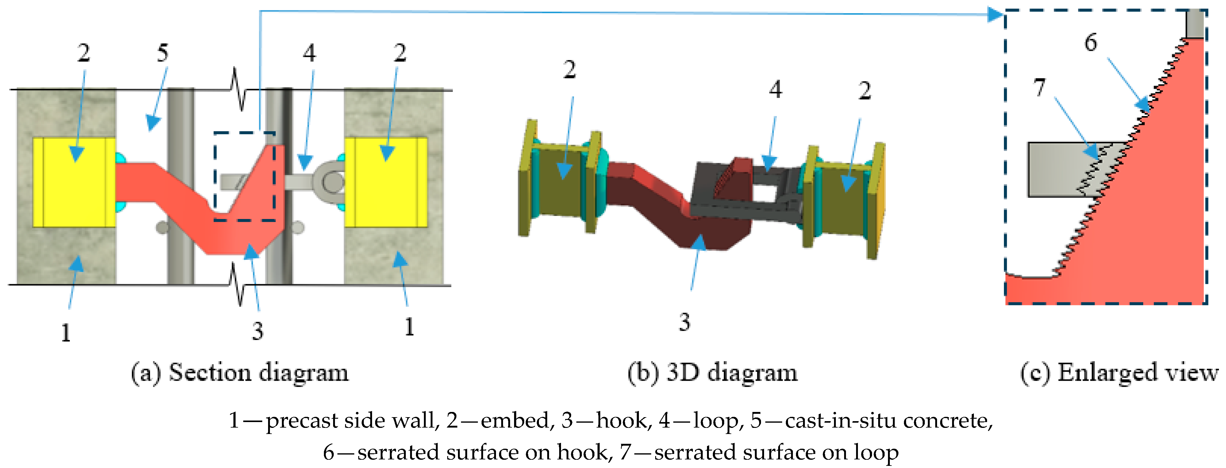
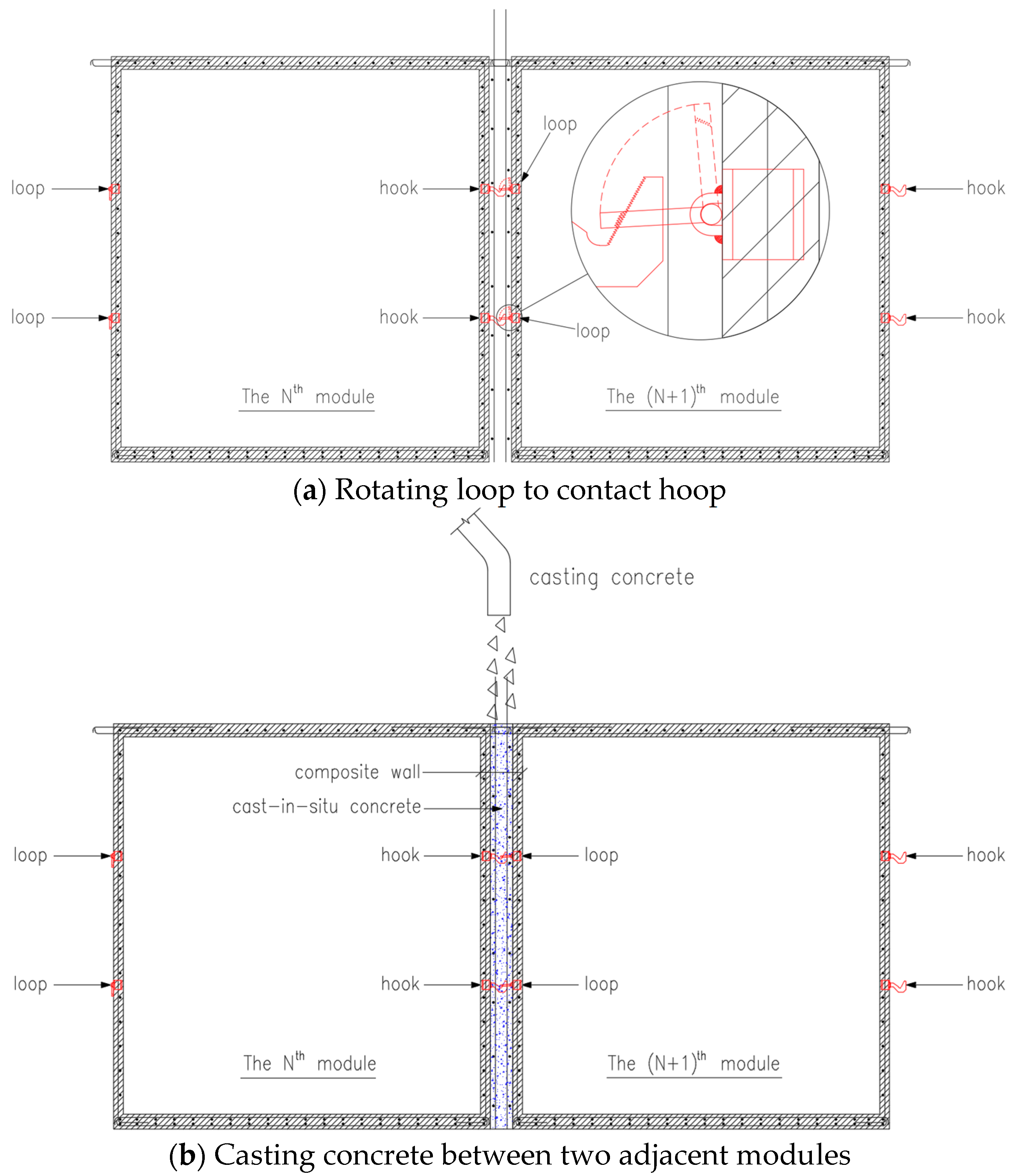
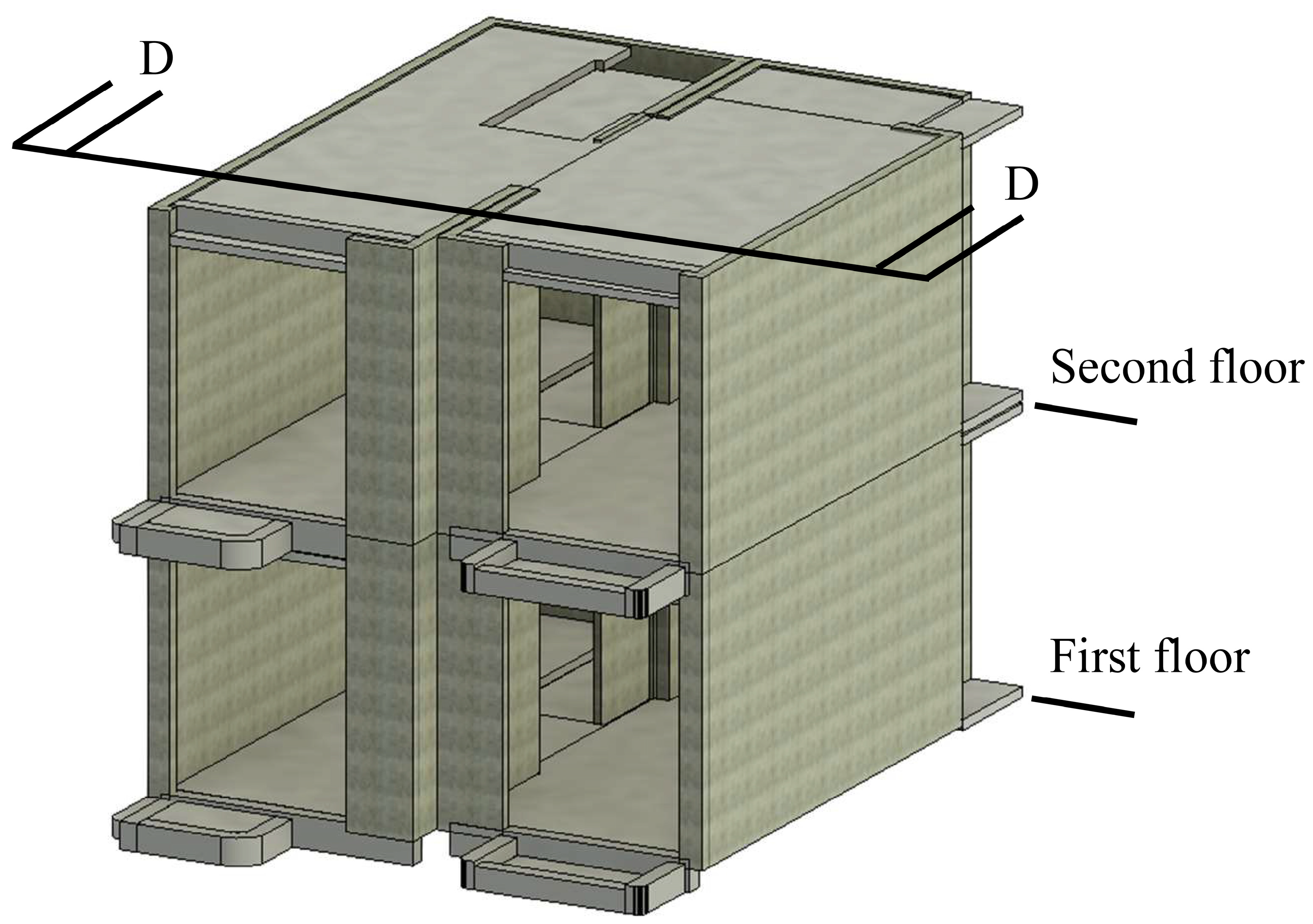
2. Mechanism of the System
- (1)
- The modules are prefabricated in the factory, and embeds are installed in the side walls.
- (2)
- The hooks are welded to the steel plates in the end of the embeds, and the loop holders with loops are welded to the end steel plates of the embeds.
- (3)
- The N-th module is installed on-site.
- (4)
- Rebars are fixed between the two modules. The loops of the (N + 1)-th module are pulled upward with ropes and the ropes are fixed onto the top of the (N + 1)-th module.
- (5)
- The (N + 1)-th module is installed on-site.
- (6)
- The worker cuts the ropes from the top of the module to release loops, and the loops fall to the left under their self-weight, as shown in Figure 3a.
- (7)
- Concrete is poured into the gap between the N-th and (N + 1)-th modules, as shown in Figure 3b.
3. Numerical Simulation for the Inner Tie System
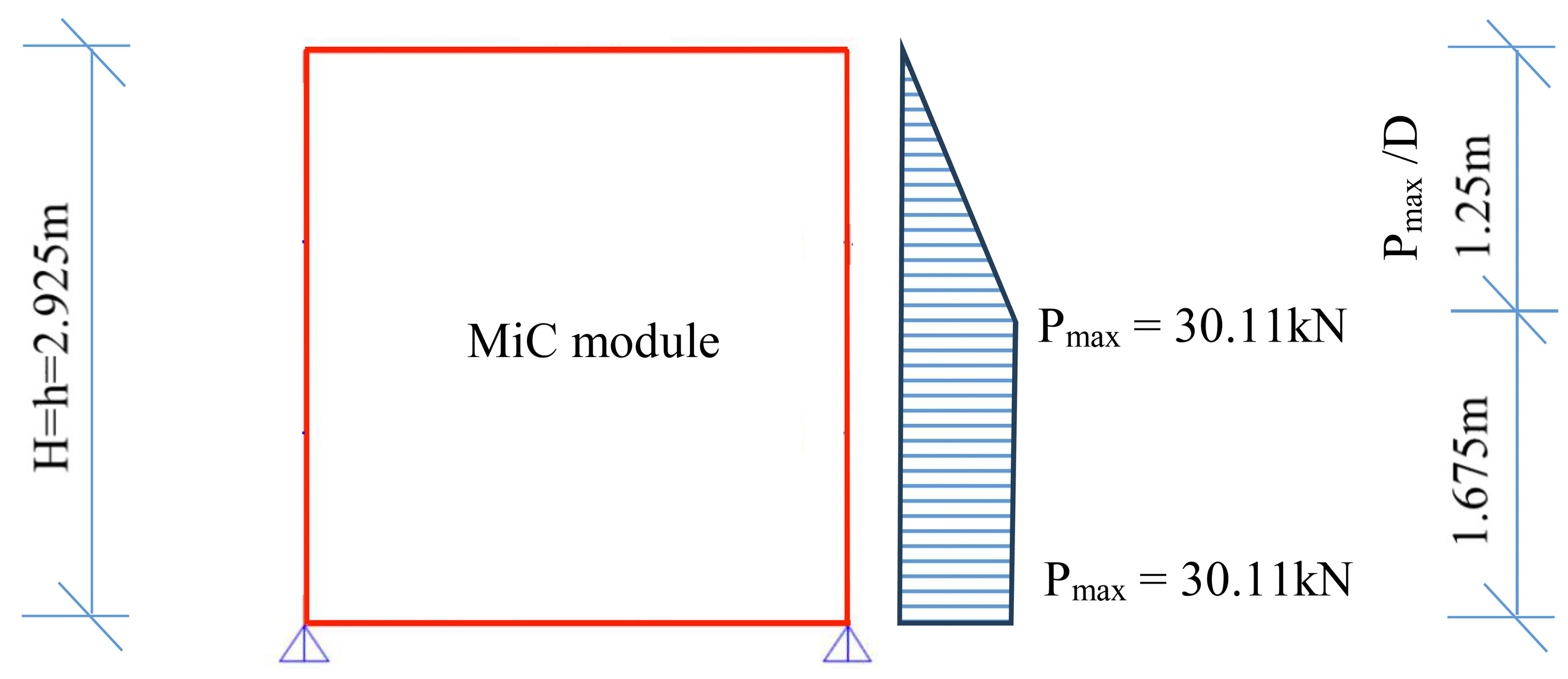
3.1. Design Parameters
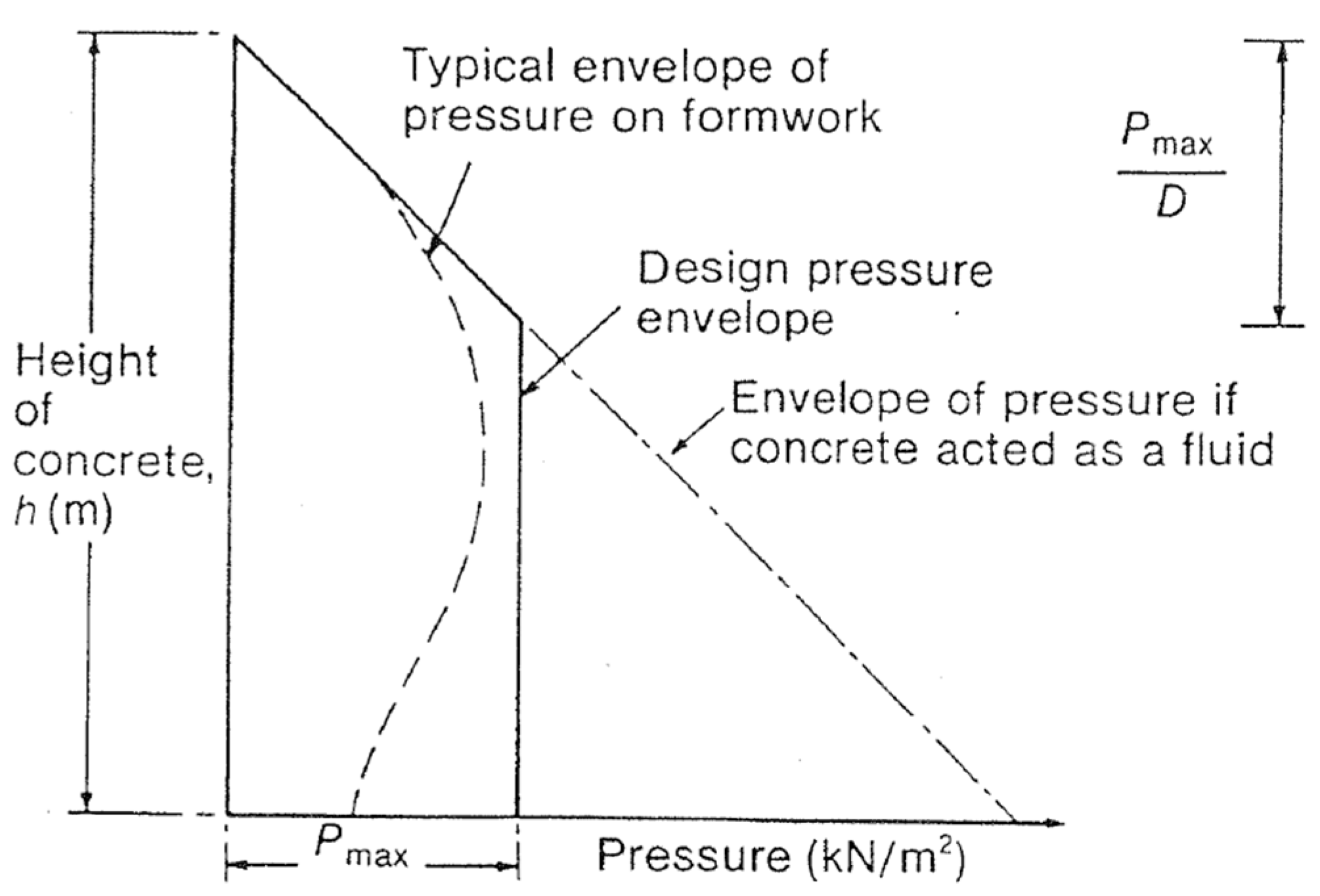
3.2. Tension Force and Initial Tie Member Sizes
- C1—is the coefficient dependent on the size and shape of formwork;
- C2—coefficient dependent on the constituent materials of the concrete;
- D—weight density of concrete;
- H—vertical form height;
- h—vertical pour height;
- T—concrete temperature at placing;
- K—temperature coefficient taken as ;
- R—the rate at which the concrete rises vertically up the form.
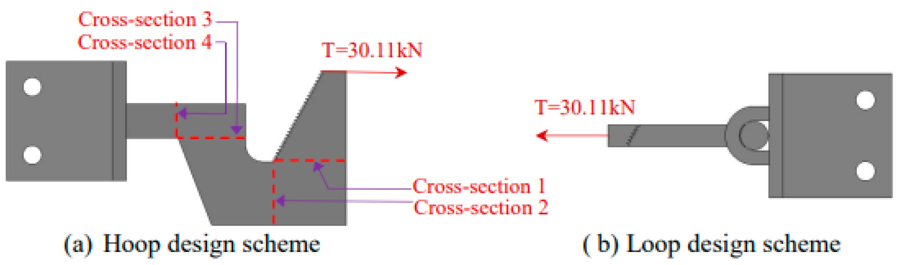
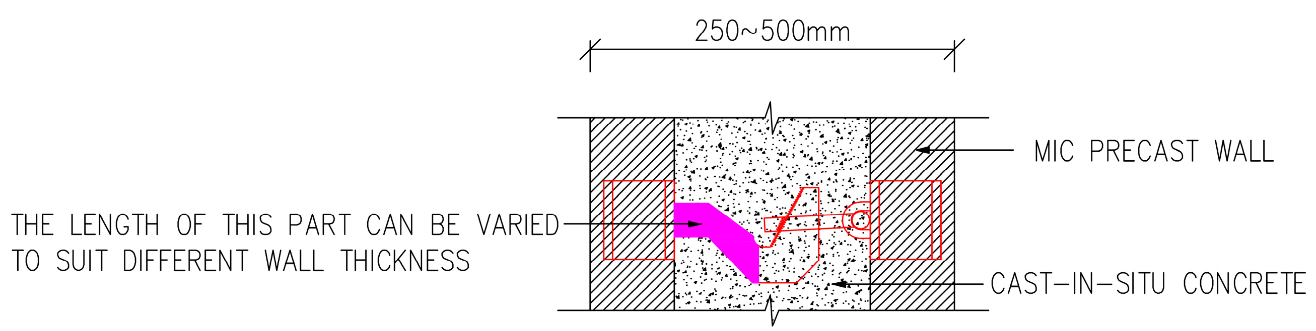
3.3. Serrated Surface Design
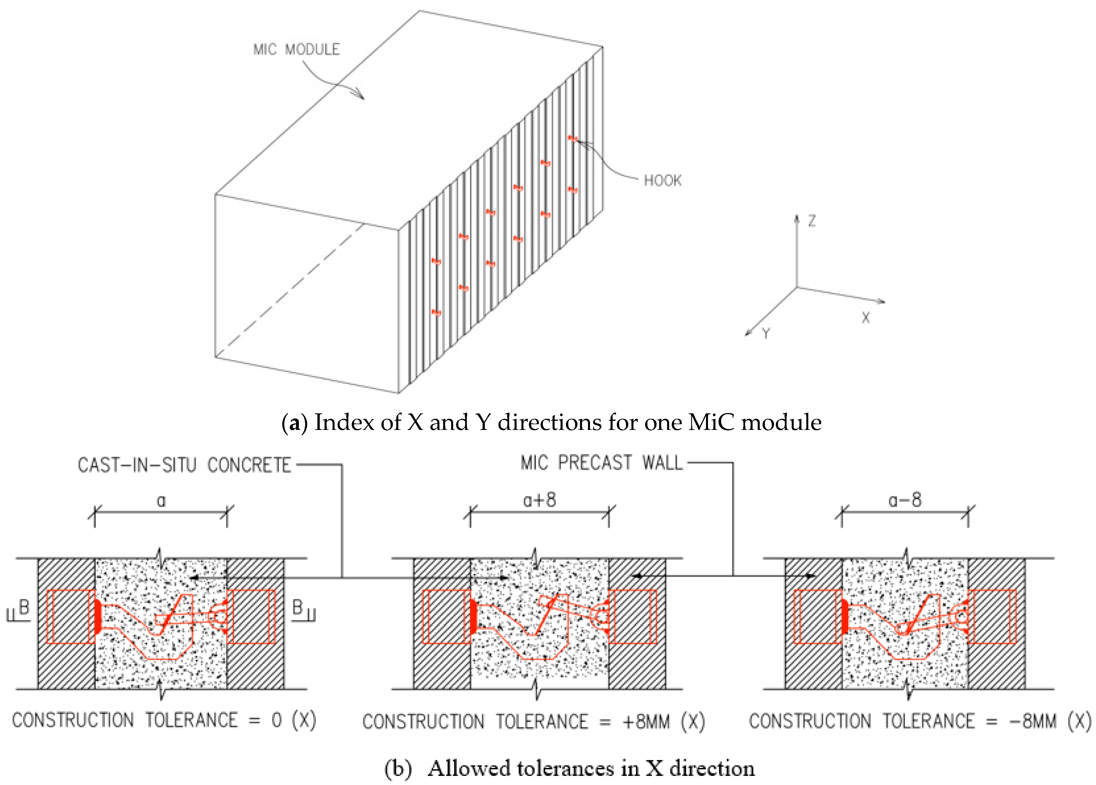
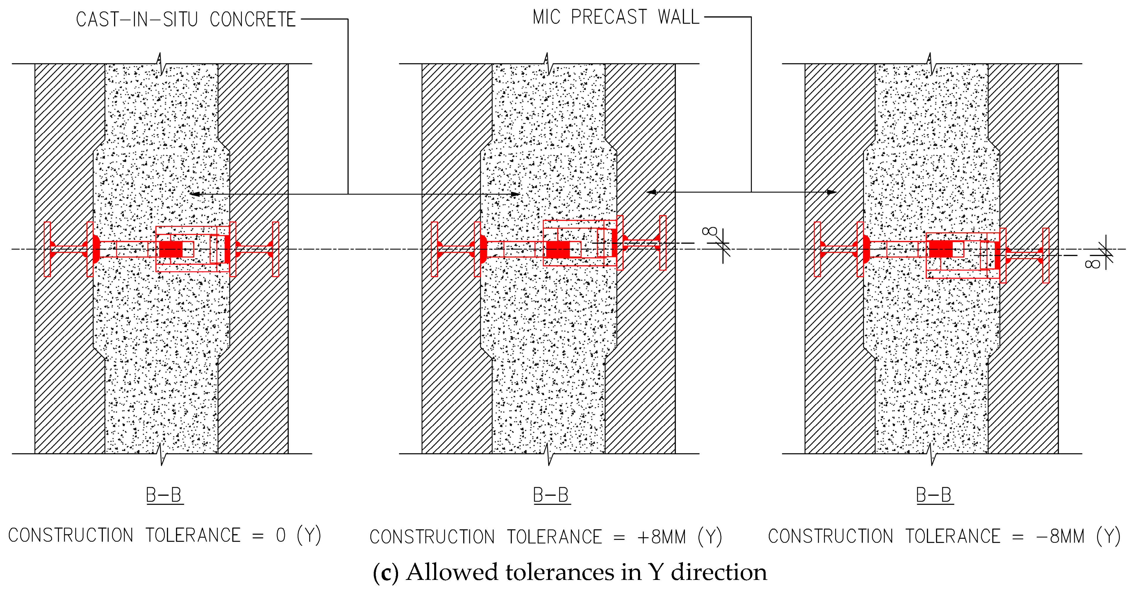
3.4. Construction Tolerances
- Case 1: +8 mm construction tolerance in X direction, no tolerance in Y direction;
- Case 2: no construction tolerance in X and Y directions;
- Case 3: −8 mm construction tolerance in X direction, no tolerance in Y direction.
- Case 4: +8 mm construction tolerance in X direction, +8 mm tolerance in Y direction;
- Case 5: no construction tolerance in X direction, +8 mm tolerance in Y direction;
- Case 6: −8 mm construction tolerance in X direction, +8 mm tolerance in Y direction.
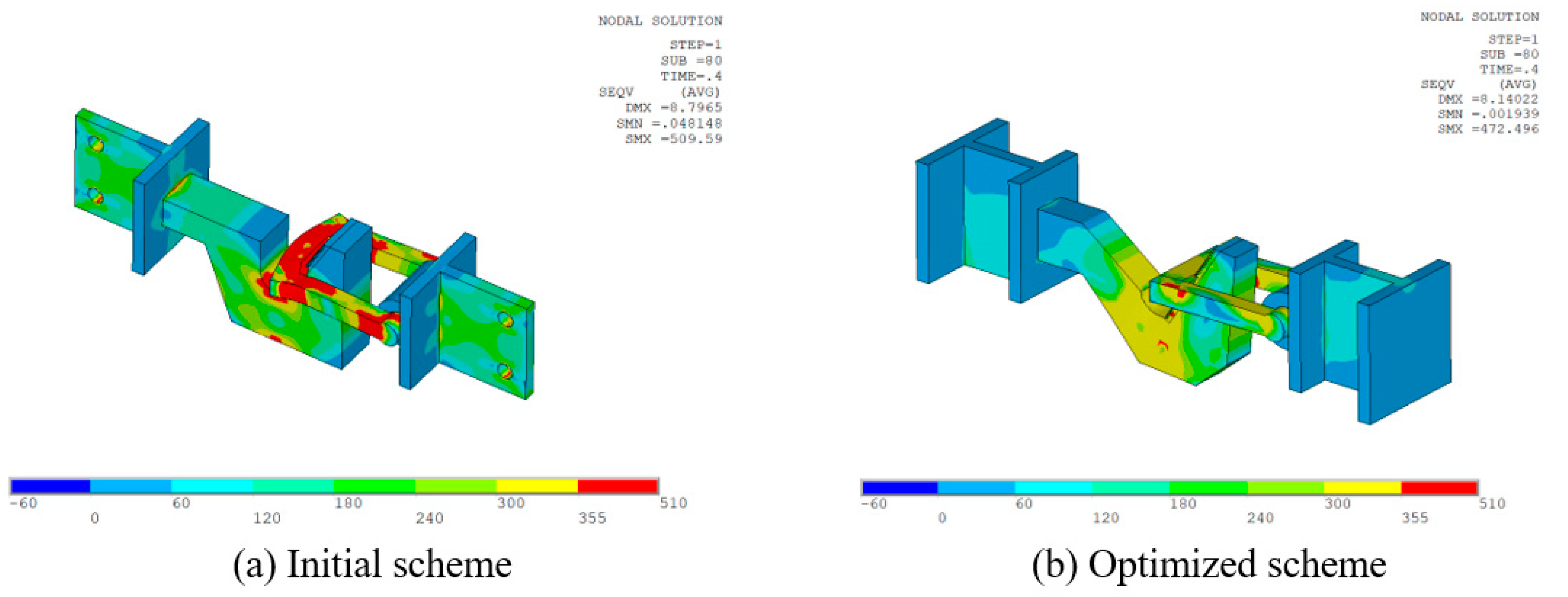
3.5. Optimized Scheme and Section Sizes
4. Experimental Verification
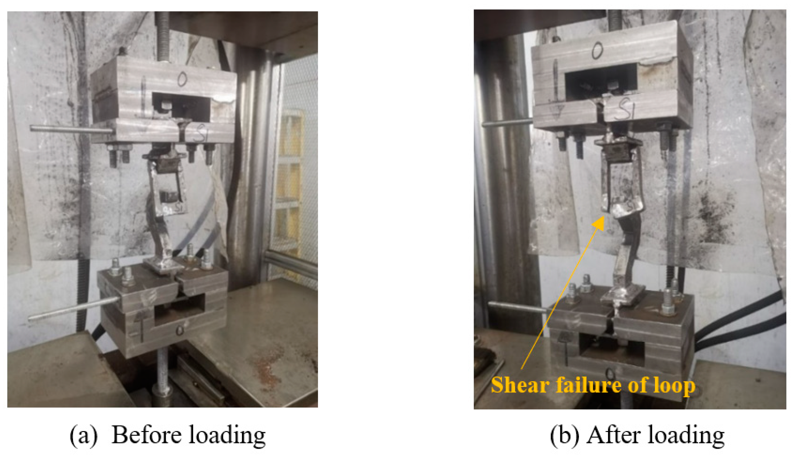
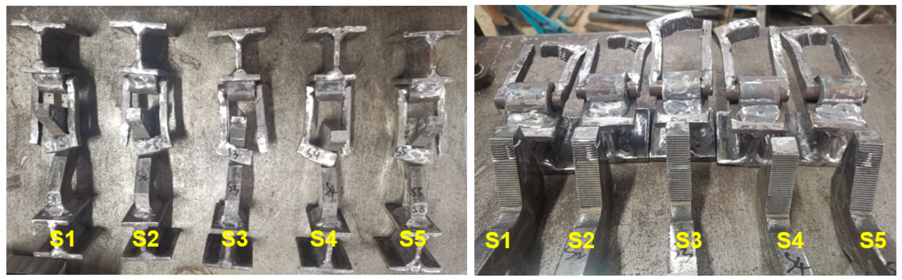
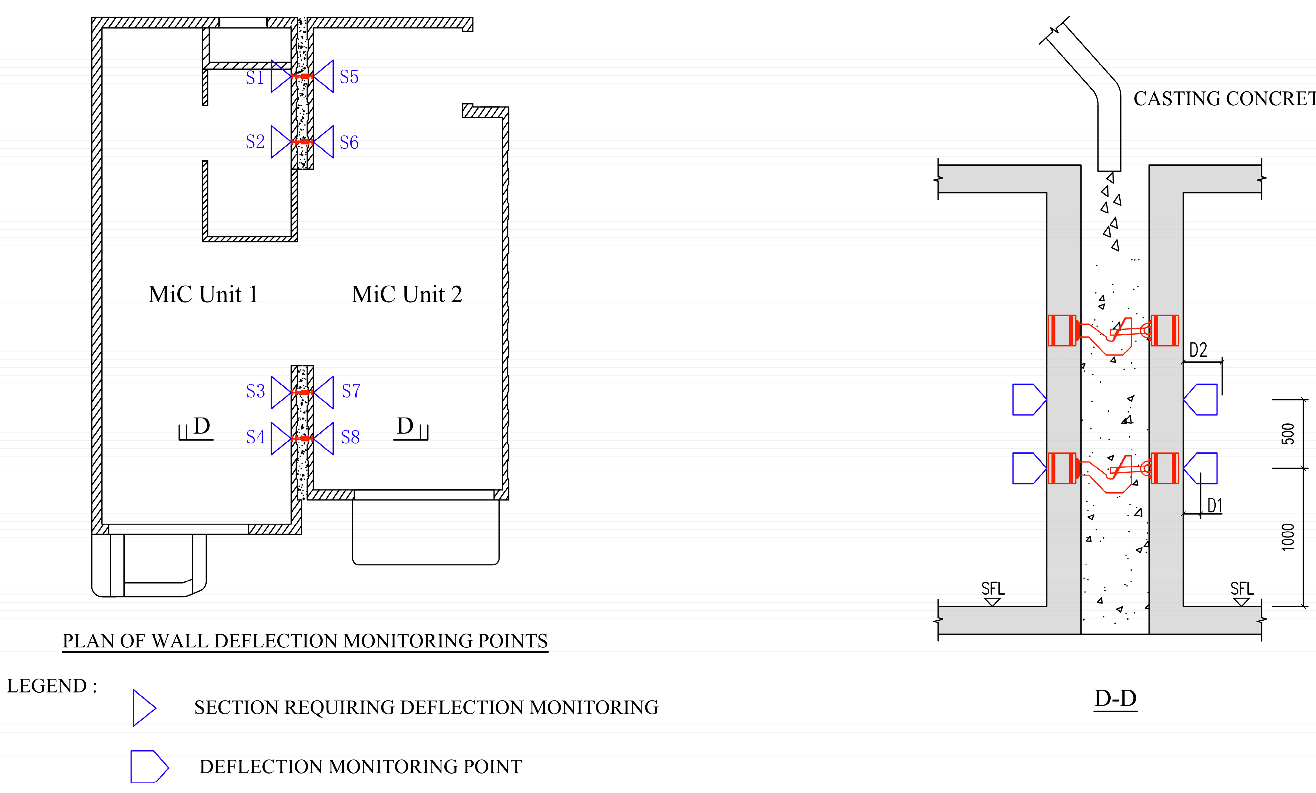
4.1. Tensile Test
- S1, S2, and S5: construction tolerance of +8 mm only in X direction;
- S3: no construction tolerance;
- S4: construction tolerance of −8 mm only in X direction.
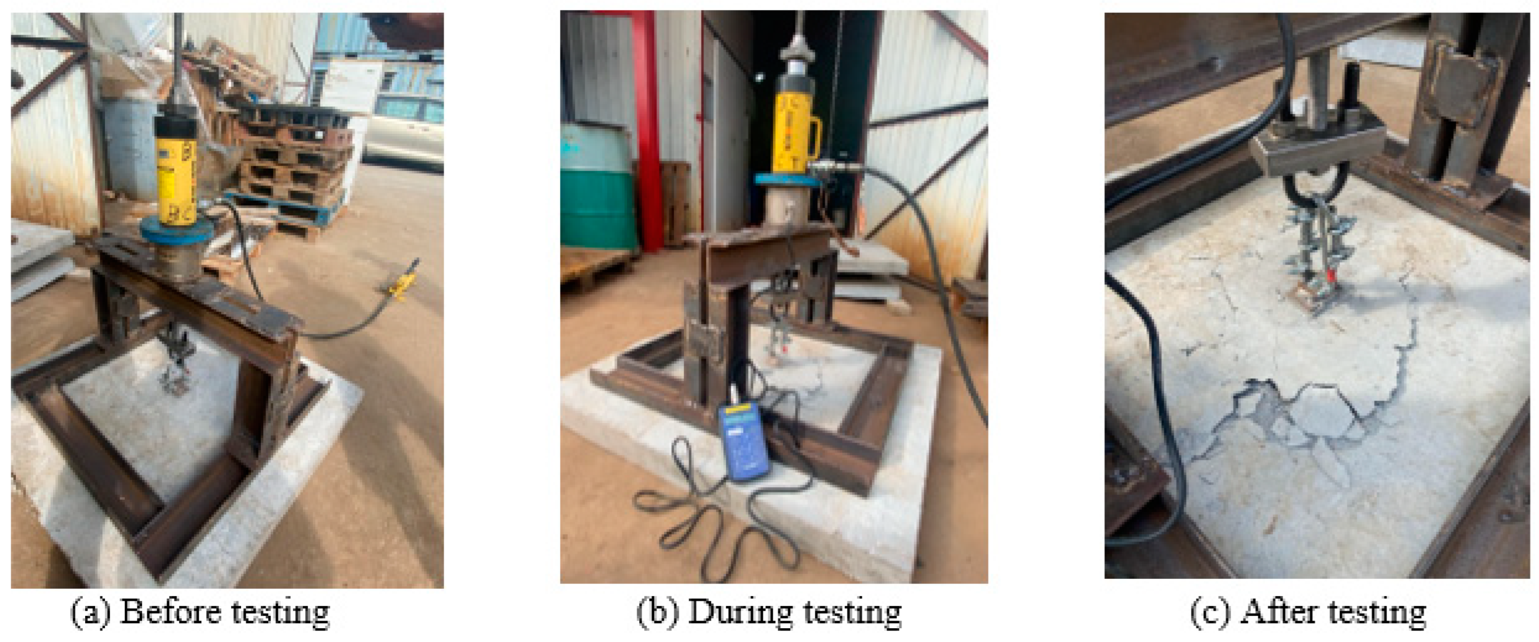
4.2. Punching Shear Test
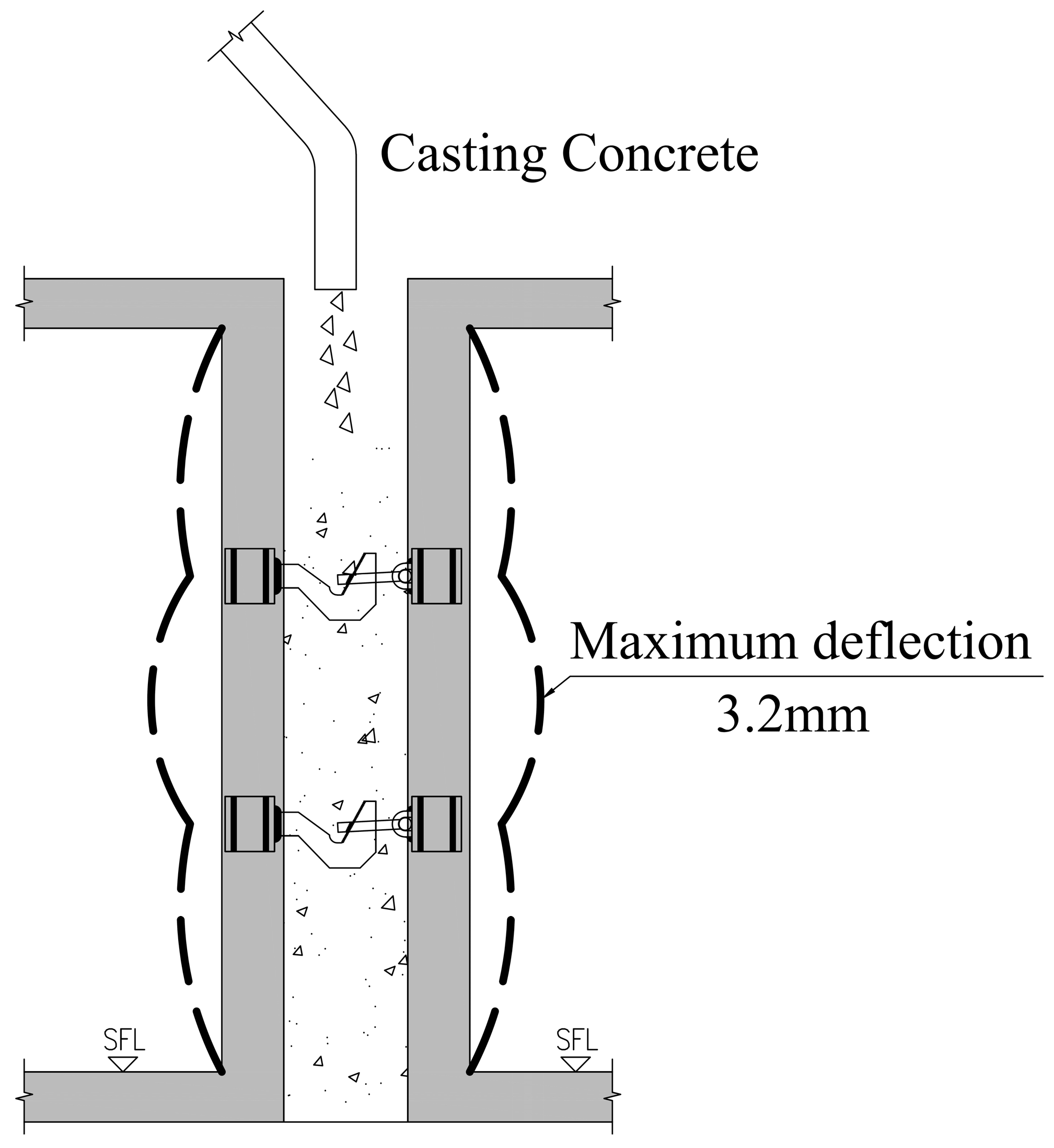
5. Estimated Deformation and Further Analysis Modified by the Test Results
6. Practical Application
6.1. Application Scope of the Inner Tie System
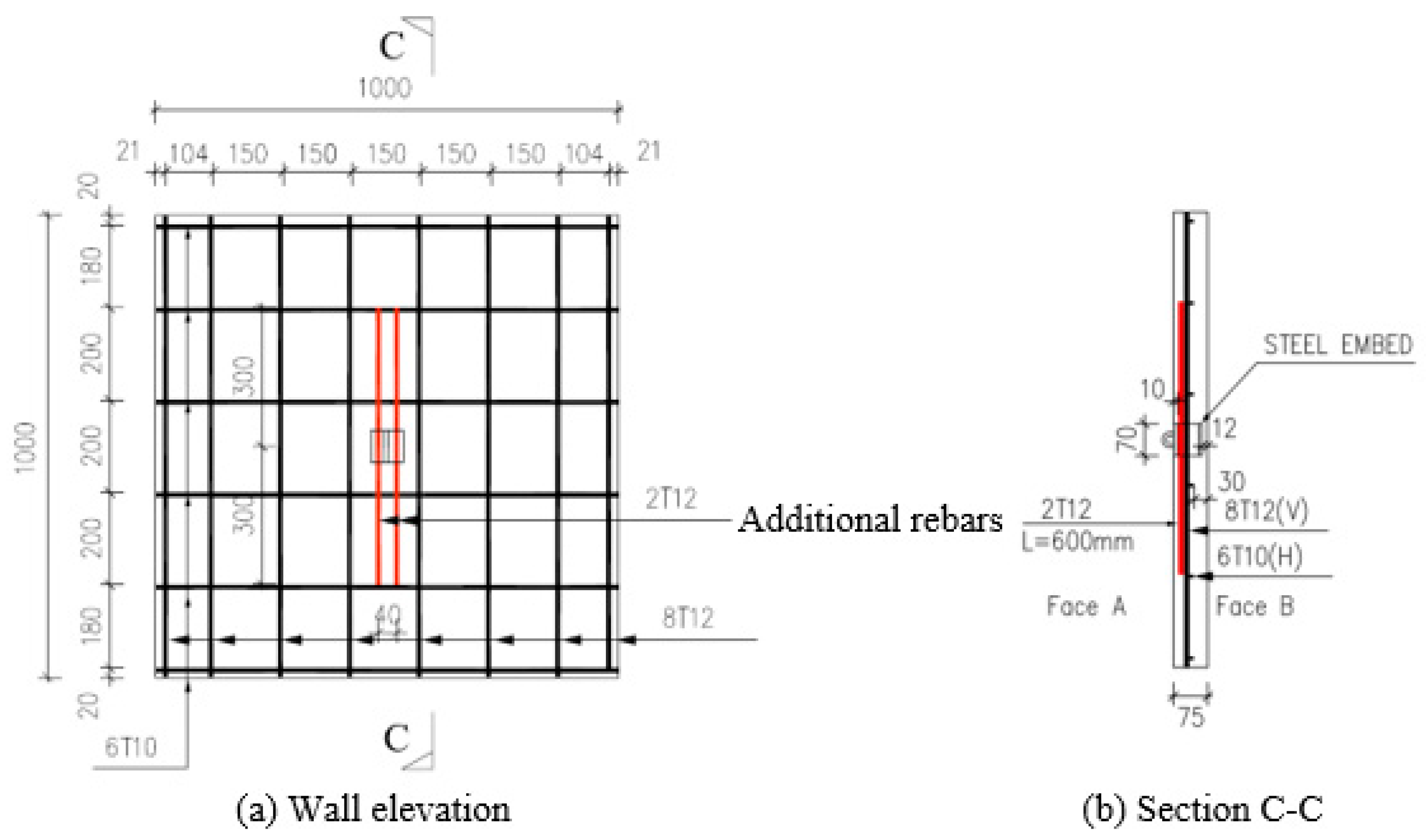
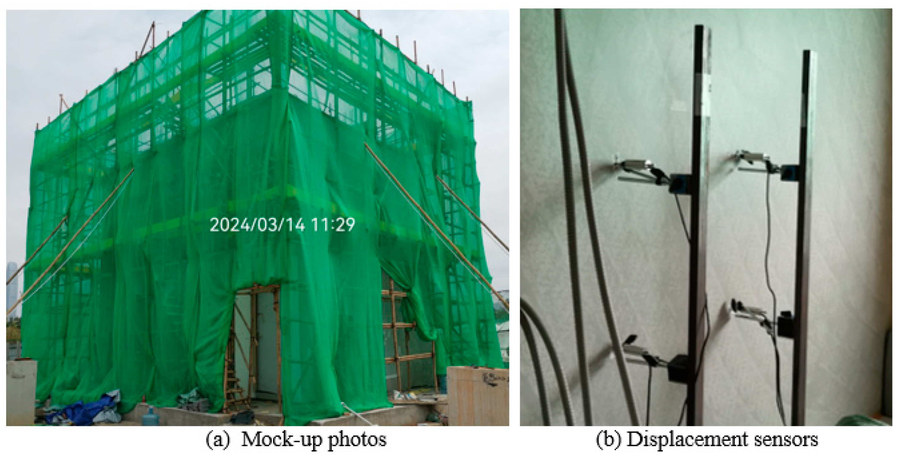
6.2. Mockup Assembly and Monitoring
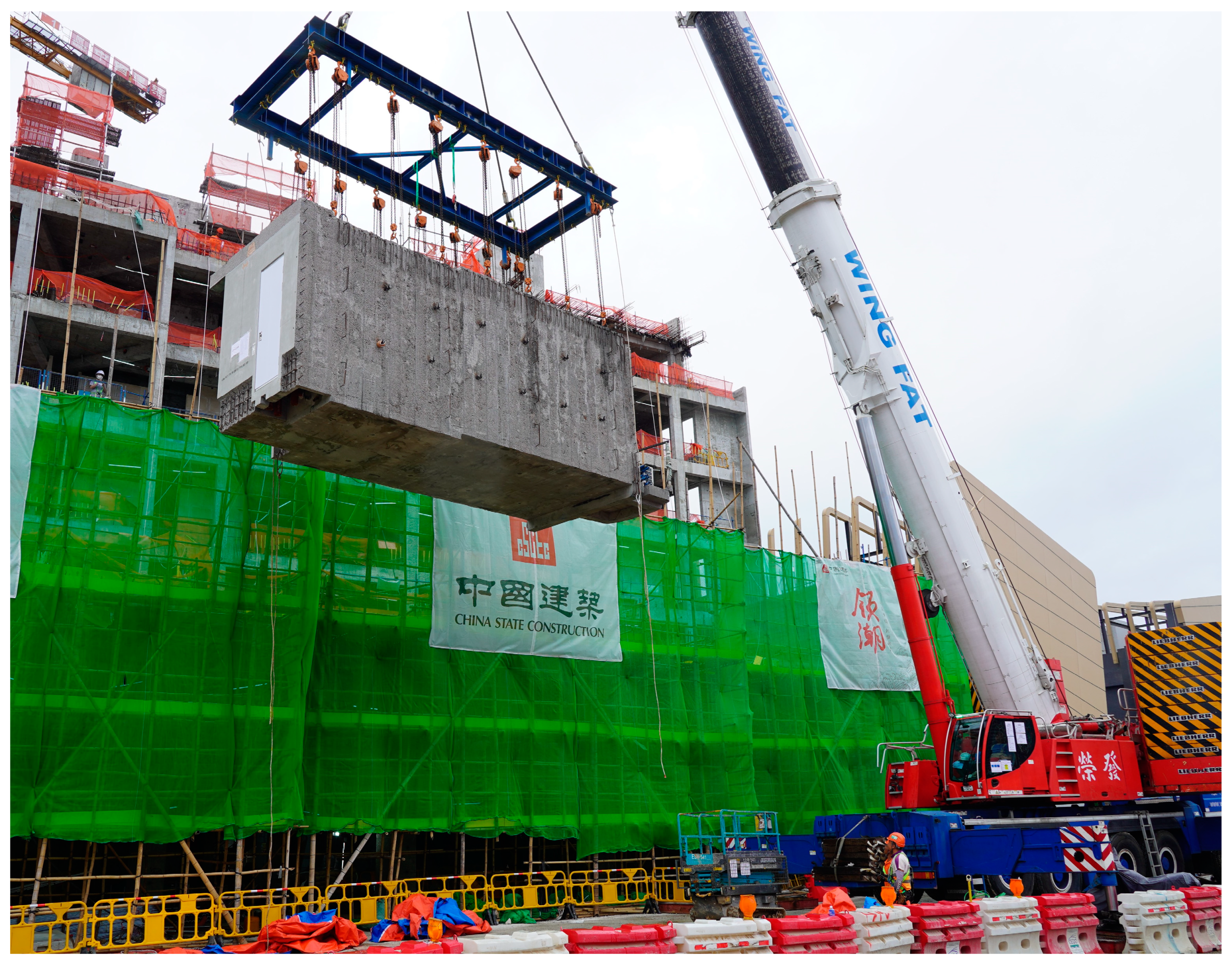
6.3. Application in a Real Project
7. Conclusions
Author Contributions
Funding
Data Availability Statement
Acknowledgments
Conflicts of Interest
References
- Hu, H.S.; Xia, H.J. A Type of Modular Shear Wall Structure and Its Construction Method. China Patent CN115807499B, 25 April 2023. [Google Scholar]
- Ji, J.; Huang, G.X.; Feng, Z.H.; Lin, J.C.; Chen, Q.J.; Tan, Z.X.; Li, P.L. A Type of Composite Modular Integrated Construction Structure. China Patent CN115045534A, 13 September 2022. [Google Scholar]
- Duan, L.J.; Yu, Y.S.; Wang, T.; Fu, C.C. Experimental Research on Mechanical Behavior of Prefabricated Prefinished Volumetric Construction Connections. J. Qingdao Univ. Technol. 2022, 43, 1–7. [Google Scholar]
- Pan, W.; Wang, Z.; Zhang, Y.; Zhang, Z.Q. Horizontal Connection Joint and Construction Method of Multi-Story and High-Rise Concrete MiC Buildings. China Patent CN116084591A, 9 May 2023. [Google Scholar]
- Li, Z.; Wang, Q.; Zhang, J.Y.; Chen, C.J.; Zhang, Z.; Ding, T.; Chen, J.; Lan, Z.L.; Zhang, Y. A Type of MiC Building with Mixed Wall Structures. China Patent CN219794297U, 3 October 2023. [Google Scholar]
- Yao, J.; Huang, M.Y.; Zeng, Z.X.; Wu, C.; Zeng, W.L.; Xu, X.; Tan, P.; Ding, T. A Type of Concrete MiC Module. China Patent CN219527957U, 15 August 2023. [Google Scholar]
- Poon, C.M.; Ma, M.C.; Li, Z.; Zhang, Z.; Chen, Z.H.; Xie, J.H.; Mei, K.L.; Liu, Y.L. A Type of Concrete MiC Structural System and Its Construction Method. China Patent CN117127714A, 28 November 2023. [Google Scholar]
- Qaidi, S.M.A.; Tayeh, B.A.; Zeyad, A.M.; de Azevedo, A.R.G.; Ahmed, H.U.; Emad, W. Recycling of mine tailings for the geopolymers production: A systematic review. Case Stud. Constr. Mater. 2022, 16, e00933. [Google Scholar] [CrossRef]
- Qaidi, S.M.A.; Dinkha, Y.Z.; Haido, J.H.; Ali, M.H.; Tayeh, B.A. Engineering properties of sustainable green concrete incorporating eco-friendly aggregate of crumb rubber: A review. J. Clean. Prod. 2021, 324, 129251. [Google Scholar] [CrossRef]
- Izadifar, M.; Dolado, J.S.; Thissen, P.; Ukrainczyk, N.; Koenders, E.; Ayuela, A. Theoretical Elastic Constants of Tobermorite Enhanced with Reduced Graphene Oxide through Hydroxyl vs. Epoxy Functionalization: A First-Principles Study. J. Phys. Chem. C 2023, 127, 18117–18126. [Google Scholar] [CrossRef]
- Zou, X.K.; Huang, J.; Lu, W.J.; Shi, J.; Zhao, Z.; Shi, T. A New Composite Wall Inner Tie System Applied in Reinforced Concrete Modular Integrated Construction. In Proceedings of the 10th International Conference on Construction Engineering and Project Management, Sapporo, Japan, 29 July–1 August 2024; pp. 85–92. [Google Scholar]
- Chan, C.M.; Zou, X.K. Elastic and Inelastic Drift Performance Optimization for Reinforced Concrete Buildings under Earthquake Loads. Earthq. Eng. Struct. Dyn. 2004, 33, 929–950. [Google Scholar] [CrossRef]
- Zou, X.K.; Chan, C.M. Optimal Seismic Performance-Based Design of Reinforced Concrete Buildings Using Nonlinear Pushover Analysis. Eng. Struct. 2005, 27, 1289–1302. [Google Scholar] [CrossRef]
- Zou, X.K.; Chan, C.M. An Optimal Resizing Technique for Seismic Drift Design of Concrete Buildings Subjected to Response Spectrum and Time History Loadings. Comput. Struct. 2005, 83, 1689–1704. [Google Scholar] [CrossRef]
- Zou, X.K.; Chan, C.M.; Li, G.; Wang, Q. Multiobjective Optimization for Performance-Based Design of Concrete Structures. J. Struct. Eng. 2007, 133, 1462–1474. [Google Scholar] [CrossRef]
- Zou, X.K.; Teng, J.G.; Xia, S.H.; Wong, Y.L. Optimal Performance-Based Seismic Retrofit Design of FRP-confined Concrete Buildings. Compos. Part B Eng. 2007, 38, 584–597. [Google Scholar] [CrossRef]
- Zou, X.K.; Wang, Q.; Li, G.; Chan, C.M. Integrated Reliability-Based Seismic Drift Design Optimization of Base-Isolated Concrete Buildings. J. Struct. Eng. 2010, 136, 1282–1295. [Google Scholar] [CrossRef]
- Zou, X.K.; Zhang, Y.; Liu, Y.P.; Shi, L.C.; Kan, D. Design and Construction of High-Performance Long-Span Steel Transfer Twin Trusses Applied in One Hospital Building in Hong Kong. Buildings 2023, 13, 751. [Google Scholar] [CrossRef]
- Clear, C.A.; Harrison, T.A. CIRIA Report 108—Concrete Pressure on Formwork; Construction Industry Research and Information Association: London, UK, 1985. [Google Scholar]
- Buildings Department of Hong Kong SAR Government. Code of Practice for the Structural Use of Steel 2011, 2023 ed.; Buildings Department of Hong Kong SAR Government: Hong Kong, China, 2023.


| Steel Grade | Steel Thickness (mm) | Design Strength py (N/mm2) | Elastic Modulus (N/mm2) | Poisson’s Ratio |
|---|---|---|---|---|
| S355J0 | ≤16 | 355 | 2.05 × 10⁵ | 0.3 |
| >16, ≤40 | 345 |
| Variable | C1 | C2 | D | H | h | T | K | R |
|---|---|---|---|---|---|---|---|---|
| Value | 1.0 | 0.3 | 24.0 kN/m3 | 2.925 m | 2.925 m | 30 °C | 0.612 | 1.0 m/h |
| Item | Initial Scheme | Optimized Scheme | ||
|---|---|---|---|---|
| Section Width (mm) | Section Thickness (mm) | Section Width (mm) | Section Thickness (mm) | |
| Cross-section 1 | 44 | 30 | 44 | 20 |
| Cross-section 2 | 37 | 30 | 32 | 20 |
| Cross-section 3 | 40 | 30 | Not Applicable | Not Applicable |
| Cross-section 4 | 20 | 30 | 30 | 20 |
| Weight | 1.56 kg | 0.88 kg (43.6% reduction) | ||
| Case | Tension at 8 mm Deformation (kN) |
|---|---|
| Case 1 | 34.20 |
| Case 2 | 63.97 |
| Case 3 | 68.97 |
| Case 4 | 38.08 |
| Case 5 | 64.38 |
| Case 6 | 66.58 |
| Steel Grade | Steel Thickness (mm) | Yield Strength py (N/mm2) | Ultimate Strength fu (N/mm2) |
|---|---|---|---|
| S355J0 | 16 | 418~459 | 549~566 |
| 20 | 384~429 | 521~536 |
| Case | Test Sample | Tension at 8 mm Deformation TTest (kN) |
|---|---|---|
| Case 1 | S1 | 33 |
| S2 | 33 | |
| S5 | 31 | |
| Case 2 | S3 | 43 |
| Case 3 | S4 | 51 |
| Case | Test Sample | Ultimate Tension (kN) | Ultimate Deformation (mm) |
|---|---|---|---|
| Case 1 | S1 | 53.8 | 29.1 |
| S2 | 51.0 | 26.4 | |
| S5 | 47.7 | 24.0 | |
| Case 2 | S3 | 59.9 | 23.0 |
| Case 3 | S4 | 62.5 | 13.5 |
| Wall Panel Sample | Ultimate Punching Shear Tu (kN) | Design Punching Shear Capacity Equivalent to C45 Concrete TC45 (kN) | Average Capacity of TC45 (kN) |
|---|---|---|---|
| W1 | 47.1 | 34.1 | 35.6 |
| W2 | 56.3 | 40.7 | |
| W3 | 44.1 | 31.9 |
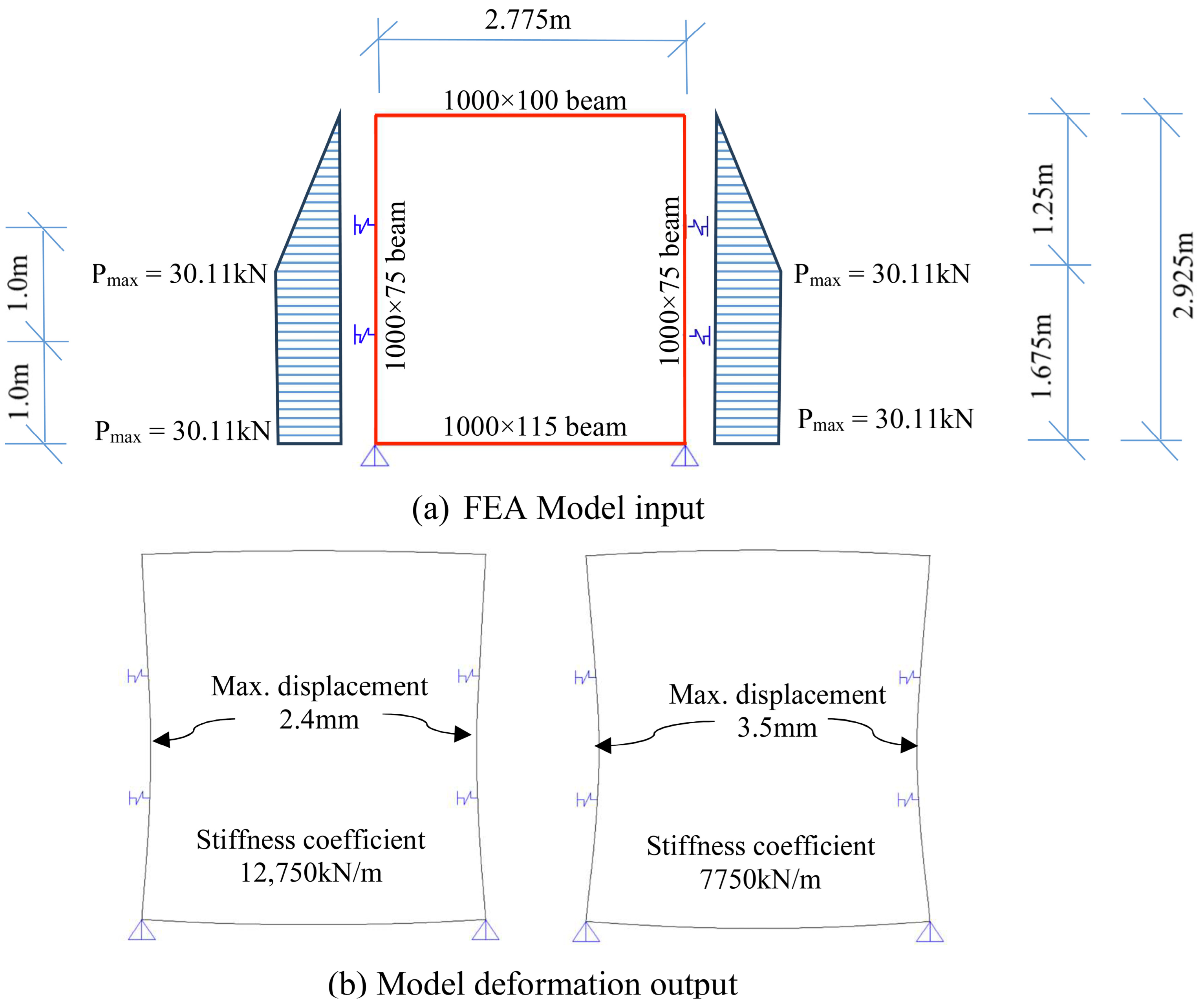
| FEA Input | FEA Output | |||
|---|---|---|---|---|
| Test Sample | Tension at 8 mm Deformation TTest (kN) | Inner Tie Stiffness (kN/m) | Hor. Displacement of Side Wall (mm) | Unfactored Inner Tie Tensile Force (kN) |
| S4 | 51 | 12,750 (Upper bound) | 2.4 (<4.0, OK) | 27.2 (27.2 × 1.2 * = 32.6 < 35.6, OK) |
| S5 | 31 | 7750 (Lower bound) | 3.5 (<4.0, OK) | 23.6 (23.6 × 1.2 * = 28.3 < 35.6, OK) |
Disclaimer/Publisher’s Note: The statements, opinions and data contained in all publications are solely those of the individual author(s) and contributor(s) and not of MDPI and/or the editor(s). MDPI and/or the editor(s) disclaim responsibility for any injury to people or property resulting from any ideas, methods, instructions or products referred to in the content. |
© 2024 by the authors. Licensee MDPI, Basel, Switzerland. This article is an open access article distributed under the terms and conditions of the Creative Commons Attribution (CC BY) license (https://creativecommons.org/licenses/by/4.0/).
Share and Cite
Zou, X.; Huang, J.; Lu, W.; Shi, J.; Au, S.; Zhao, Z.; Shi, T.; Kan, D.; Zhang, Y. An Innovative Composite Wall Inner Tie System Applied to Reinforced Concrete Modular Integrated Construction. Buildings 2024, 14, 3052. https://doi.org/10.3390/buildings14103052
Zou X, Huang J, Lu W, Shi J, Au S, Zhao Z, Shi T, Kan D, Zhang Y. An Innovative Composite Wall Inner Tie System Applied to Reinforced Concrete Modular Integrated Construction. Buildings. 2024; 14(10):3052. https://doi.org/10.3390/buildings14103052
Chicago/Turabian StyleZou, Xiaokang, Jiang Huang, Wenjie Lu, Jun Shi, Sunny Au, Zhen Zhao, Tian Shi, Daniel Kan, and Yang Zhang. 2024. "An Innovative Composite Wall Inner Tie System Applied to Reinforced Concrete Modular Integrated Construction" Buildings 14, no. 10: 3052. https://doi.org/10.3390/buildings14103052
APA StyleZou, X., Huang, J., Lu, W., Shi, J., Au, S., Zhao, Z., Shi, T., Kan, D., & Zhang, Y. (2024). An Innovative Composite Wall Inner Tie System Applied to Reinforced Concrete Modular Integrated Construction. Buildings, 14(10), 3052. https://doi.org/10.3390/buildings14103052