Abstract
The utilization of externally bonded carbon fiber-reinforced polymers (CFRPs) and glass fiber-reinforced polymers (GFRPs) for reinforcing and retrofitting components has garnered considerable interest recently, as such composites provide beneficial properties, including a high modulus of elasticity, high strength, and low weight. This work conducts a finite element analysis, verified through laboratory experiments on 14 reinforced concrete (RC) beams. The primary focus is the final load of these components, considering varying CFRP orientations relative to the loading direction. In this research, the performances of control beams and RC beams are compared to assess the effectiveness and efficiency of different strengthening methods. The results demonstrated that bonding CFRP sheets with V-shaped end anchorages on the tension side was highly effective in improving the flexural capacity of RC beams in the weaker concrete strength group. This strengthening method resulted in a substantial increase in strength (of around 29.8%) in the higher concrete strength group. In addition, utilizing V-shaped end anchorages to bond CFRP sheets on the tension side proved to be a highly efficient technique for improving flexural strength. Conversely, bonding inclined CFRP strips to the sides of RC beams was highly effective at enhancing the shear capacity of the beams. These outcomes convincingly demonstrate the effectiveness of FRP for the reinforcement of structural components. The specimens strengthened with inclined strips exhibited enhanced shear and deformation capacity compared to those strengthened with vertical strips.
1. Introduction
When bonding (carbon fiber-reinforced polymer) CFRP sheets with U-shaped end anchorages or in span, column, and slab configurations, each CFRP sheet is positioned perpendicular to the loading direction. This alignment allows the CFRP sheet to bear the load by stretching it along its primary direction. However, when bonding CFRP strips to the sides of reinforced concrete (RC) beams at an inclined angle, the loading direction and the fiber orientation of the CFRPs become parallel. Consequently, each CFRP experiences contraction along its fiber direction, resulting in a reduced contribution to the ultimate failure load. Finite element method (FEM) simulations and previous experiments have revealed a significant difference in the ultimate strength of RC beams strengthened with CFRP sheets on their sides. FEM simulations can effectively capture the behavior of RC members and help to accurately assess the contribution of fiber-reinforced polymer (FRP) to the ultimate strength of beams bonded with CFRP sheets in U-shaped, column, and slab configurations. However, the results obtained from experiments differ slightly from those of numerical simulations regarding RC beams with inclined CFRP strips bonded to their sides. Therefore, further investigation is needed on the behavior of concrete beams reinforced with CFRP.
To accurately assess the impact of the boundary conditions on the ultimate strength of RC beams, we must consider the size and position of the CFRP component and examine various FRP patterns to determine optimal strengthening solutions for practical applications. A simplified guideline or formula is essential for the engineering implementation of strengthened beams. By comparing control beams with strengthened beams, we can assess the effectiveness and efficiency of different approaches. While bonding CFRP sheets to the tension side of the beams using U-shaped end anchorages increases the flexural strength significantly, bonding inclined CFRP strips to the sides of RC beams increases their shear strength. To provide reliable recommendations, a comprehensive experimental and numerical analysis is being conducted at Adnan Menderes University.
The utilization of FRP materials has brought about a significant transformation in strengthening concrete structures [1]. In traditional techniques, FRP is user-friendly, long-lasting, and easy to install, and it exerts minimal impact on the weight and size of the structure [2,3,4,5,6,7,8]. Numerous experimental studies [9,10,11,12,13,14,15,16,17] and national standard codes [18,19,20,21] have acknowledged the applications of FRP, although further investigation is required to understand its behavior in specific scenarios. Furthermore, despite the substantial amount of experimental work conducted in this field [16,22,23,24,25], limited exploration has utilized the FEM to understand the behavior of CFRP-containing Reinforced Concrete (RC) beams placed in the parallel loading direction and CFRP orientations following different schemes. The objective of this study is to address the existing research gap through an investigation of the behavior of FRP confinement in centrally loaded concrete elements, with a particular focus on RC beams. We build upon previous experimental work conducted on strengthened RC beams. Numerous researchers [26,27,28,29,30,31,32] have investigated how FRP-strengthened RC beams perform under shear and flexural forms, and notable enhancements in strength and stiffness have been observed with the application of FRP materials perpendicular to cracks. An analysis of RC elements involves evaluating the load capacity of standard test results and comparing them with the predicted outcomes obtained from the ABAQUS software 6.14 [33,34,35,36,37,38,39,40,41].
Utilizing Carbon Fiber Reinforced Polymer (CFRP) for reinforcing concrete beams presents a multitude of benefits. The remarkable characteristics of CFRP, including its high strength-to-weight ratio, resistance to corrosion, and ease of installation, make it a highly desirable option for improving the performance of weakened or inadequately designed beams. There are different techniques available for reinforcing concrete beams, such as applying externally bonded CFRP laminates, utilizing near-surface mounted CFRP strips, or employing CFRP plate bonding. Each method offers distinct advantages and can be customized to meet specific project needs. Reinforced concrete beams can crack in three ways. First, flexural cracking happens when the beam’s bending capacity is surpassed by tensile stresses. These cracks usually start near the supports and extend towards the center of the beam. Secondly, shear cracking occurs when the shear reinforcement fails or when the beam does not have enough shear capacity. Shear forces play a vital role in resisting the sideways movement of the beam and are transmitted between the reinforcement and concrete. Insufficient shear reinforcement or incorrect detailing can result in shear cracks that are inclined near the supports or in areas experiencing high shear stress. Such cracks can compromise the beam’s structural integrity and load-carrying capacity. Lastly, bond cracking occurs when there is insufficient bonding between the reinforcing steel and the concrete. Factors like inadequate development length, poor concrete quality, or improper construction practices can contribute to this problem. Bond cracking hampers the transfer of forces between the reinforcement and concrete, potentially reducing the load-carrying capacity of the beam.
To validate the accuracy of the FEM simulations, comparison tests are conducted using experimental samples from previous studies [42,43,44,45], providing a cost-effective and time-efficient method for assessing the strength and performance of structural elements. To fully comprehend optimal enhancing strategies for real implementation, we need to explore the different applications of FRP patterns. A lack of clear understanding exists regarding the performance of FRP-strengthened beams in various strengthening techniques. For this current study, an experimental schedule is undertaken to examine the level of productivity and success of two distinct yet highly realistic FRP schemes to improve the shear and flexural strength of RC beams. By utilizing the data obtained from experimental tests and incorporating them into the finite element analysis, relationships between the input material properties and the derived stiffness values can be established.
2. Laboratory Setup
Previous experiments on strengthened beams [16,42] provided valuable experimental data for this study. The comprehensive data and outcomes of these trials are available in the primary research papers. This section presents a concise summary of each experiment, including material characteristics and the maximum-strength augmentation. The properties of the FRP material are described in the subsequent section. The experiments conducted on beams are designated with the labels RB (reference beam) and SB (strengthened beam). An experimental program was managed at the Department of Civil Engineering, Adnan Menderes University, to validate the success of various CFRP and (glass fiber-reinforced polymer) GFRP schemes for strengthening RC beams in terms of flexure and shear. The program involved casting 13 RC beams divided into Group 1 with lower concrete strength (30 MPa) and Group 2 with higher concrete strength (35 MPa), comprising six and seven RC beams, respectively. These were based on ACI 400.2R-08 [1].
2.1. Sample Beams
Experiments were conducted on the 13 RC beams, utilizing one reinforcement arrangement and ten FRP patterns. With a clear span of 1860 mm and a load separation of 500 mm, the beams were bent in a four-point arrangement. The results of these experiments led to the selection of two beams for numerical simulation: one with CFRP and one without. The height of the beams measured 300 mm, while their width was 200 mm, and their length extended to 2000 mm. For the longitudinal steel reinforcements, three bars measuring mm were utilized to withstand tension, and an additional mm bar was employed for the side of compression. Sufficient reinforcement for shear was achieved by incorporating mm rebars at intervals of 100 mm, as depicted in Figure 1 and Table 1. In Table 1, Epoxy LR135/LH135 is used for specimens between SB01 and SB11.
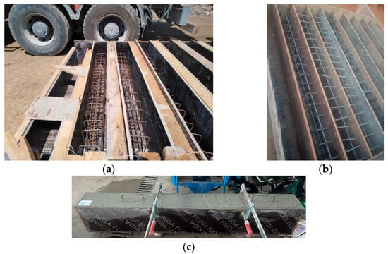
Figure 1.
Views of the reinforcement of (a) Group 1 and (b) Group 2 specimens in the mold and the (c) casting.

Table 1.
Configuration and specific information pertaining to the test specimens (units in mm).
Following the casting process (Figure 1), the specimens underwent daily intermittent water spraying for two weeks. Subsequently, they were allowed to air-dry for an additional two weeks. On the 26th day after casting, two beams were reinforced with externally bonded CFRP sheets to the surface of the concrete using epoxy coating.
2.2. Specimen Configuration
The specimens in Group 1 (SB01–SB06) were intentionally designed to have weak concrete strength, using only 0.40 m2 CFRP strips, while the specimens in Group 2 (SB07–SB13) were designed to be strong, using 0.56 m2 CFRP and GFRP strips. The last two specimens in Group 2 were strengthened with the same number of GFRP strips but two different epoxy techniques (SB12 and SB13). Within each group, one beam served as the control specimen, while the remaining RC beams were reinforced using the nine FRP schemes given in Table 1. The results of SB02 specimen are not given here due to machinery failure. SB09 is the same as SB10, which is not given in the paper. All schemes involved the external bonding of some number of FRP sheets to the bottom of the beam using epoxy. Three schemes (SB02, SB04, and SB07) were additionally U-wrapped at the supports using CFRP and GFRP strips to prevent any potential debonding; in three other schemes (SB05, SB06 and SB11), additional CFRP strips were attached to the beam sides to enhance the flexural strength; and, finally, three schemes (SB03, SB08 and SB10) were designed to prevent shear–flexural failures. For validation purposes, SB01 and SB07 were compared with the findings of Siddiqui [44] and Lima, Doh, Hadi and Miller [16]. The CFRP strips were affixed to be perpendicular to the longitudinal axis of the beam at 90 degrees. Conversely, the strips in some schemes were attached at a 45-degree angle to this axis. The strips were affixed to the surfaces of the beam using epoxy. Afterward, all beams were subjected to comparable loading, and the results were analyzed to assess the effectiveness of the presented schemes, comparing the responses of the control beams to those that had been strengthened. Using the description in Table 1, we can easily differentiate between nonstrengthened and strengthened samples with respect to each type of structural element.
This standardized approach allows for a clear identification and comparison of the experimental results across different studies.
2.3. Properties of Material
2.3.1. Steel and Concrete
In the control beams of each group, loading was continued until failure. When casting the designated test specimens, the strengths of the concrete under compressive forces were 30 MPa and 35 MPa in Groups 1 and 2, respectively. The stress required for the reinforcement to reach its yield point was 420 MPa. A batch was employed to cast all of the specimens. To control the 28-day compressive strength for the batch, six cubes with dimensions of 150 × 150 mm were cast, as displayed in Figure 2.
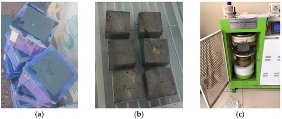
Figure 2.
Six cubes: (a) casting, (b) curing, and (c) measuring concrete strength.
To tie the CFRP sheets onto the beam surfaces, a cold-curing epoxy adhesive consisting of two components was employed with three different resin types. The adhesive exhibited a maximum strength under tension of approximately 25 MPa, while the elastic modulus was measured as 8.5 GPa. Details regarding the mechanical characteristics of the epoxy are given in Table 2.
Table 2.
The characteristics of CFRP, GFRP, and epoxy used in the present study.
2.3.2. Epoxy Resin and Hardener
Three types of epoxy systems were utilized, consisting of a ratio of two parts resin to one part hardener, mixed with a 100/35 ratio for LR135/LH135, a 2/1 ratio for LR300/LH300, and a 3.85/1.15 ratio for Tecnobond 300 TIX. The LR135/LH135 epoxy system was used for all beams strengthened with CFRP, while LR300/LH300 and Tecnobond 300 TIX were used for beams strengthened with GFRP. A dedicated mixing tool was used for each system, meticulously blending the resin and hardener by hand for at least five minutes. A thin layer of epoxy, approximately 1 mm in thickness, was then used on the concrete surface. The epoxy-treated surface was then covered with a CFRP sheet/strip. Gaps between the sheet or strip and the concrete surface were carefully removed. CFRP sheets/strips were exclusively applied for strengthening. For proper epoxy curing, the specimens were allowed to rest at room temperature for two days following their application. Table 2 presents the CFRP system properties as provided by the manufacturers.
2.4. Bonding CFRP Process
The process conducted to attach the layers to the concrete surfaces using epoxy began with the preparation of the surfaces and the removal of any excess sheets/strips. We used epoxy to secure the sheets to the concrete, removing any excess epoxy by applying pressure. Once the sheets/strips solidified, they retained their positions. Prior to the examination, the samples were kept in an accurately regulated environment at a temperature of 25 °C 2 °C and a relative humidity of 30%. Following the experiment, the sheets were secured to the beams. A CFRP sheet is typically attached to the lower side of the beam (under tension). Using CFRP sheets and U-strip anchorages at the beam extremities, two configurations were created (Figure 3). In a few schemes, CFRP strips at a angle were attached to the longitudinal axis of the beam, while, in other schemes, the strips were affixed at a angle to the same axis. Prepregs offer exceptional bonding between the fibers and matrix, consistent quality, and favorable handling properties. Fabrics made of carbon or glass consist of woven strands of these fibers. These fabrics are highly versatile and find applications in numerous fields. Woven fabrics provide reliable structural integrity and dimensional stability. Unidirectional (UD) fibers refer to carbon or glass fibers that are aligned parallel to each other, commonly in the form of tapes. UD fibers are preferred in applications that require high strength along longitudinal directions.
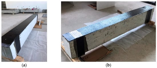
Figure 3.
The process of CFRP sheet for strengthening of beams: (a) Group 1, SB01, and (b) Group 2, SB07.
The bonding procedure employed for the external application of the sheets is shown in Figure 3. The specifications of the specimens and the quantity of FRP employed in this investigation are shown in Table 3.
Table 3.
Amount of FRP used in experimental specimens for the current study.
2.5. Test Procedure and Setup
A Besmak testing machine was employed to conduct tests on the beams. Each beam used a simple support setup and was subjected to four-point loads, loaded symmetrically at 500 mm from the beam centerline. The test setup utilized for flexure testing of the beams is illustrated in Figure 4.
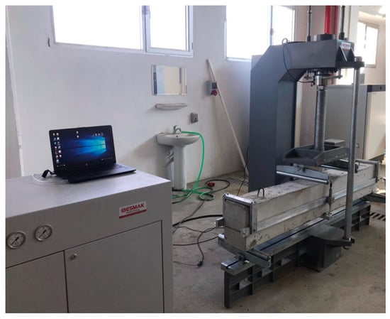
Figure 4.
Arrangement of the four-point bending test in the laboratory.
We used a linear variable displacement transducer (LVDT) to monitor central deviations, and the applied load recording system for data collection recorded the real-time LVDT displacements. External forces were continually applied, and the process was documented until the beam failed structurally. After pouring ready-mix concrete in two intervals, we separated the beams into Groups 1 and 2 based on their concrete strength characteristics. RB01 and 2RB1 were the respective reference beams for each group, respectively.
3. Numerical Methods for Material Properties
Several materials were utilized in the FEM evaluation, including steel bars, concrete, and FRP. The subsequent section discusses the insert material qualities and the models describing the material behavior. The FEM analysis incorporated various materials such as bars, concrete, and FRP. The subsequent section details the characteristics of the materials as inputs and the models employed to describe their behavior.
3.1. Steel Bars
Regarding stress–strain behavior, a steel bar is expected to behave like an elastic–perfectly plastic material. Steel reinforcement is depicted in ABAQUS as truss pieces embedded within concrete, as shown in Figure 5.
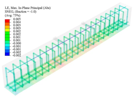
Figure 5.
Beam modeling of SB01 in Abaqus Software 2020.
We assume that the concrete and reinforcement have a perfect bond. In the FEM model, we use the yield stress provided in the previous section and an elastic modulus of 210 GPa when applicable. In all models, the reinforcement rebars are assigned a Poisson’s ratio of 0.3 as an additional consideration.
3.2. Concrete
The strength under uniaxial compression (MPa) for each sample is as provided in the previous section. This uniaxial compressive strength in Figure 6 is based on the concrete strain , which generally falls between 0.002 and 0.003. For this analysis, we utilize a value of = 0.003, as recommended by ACI318-14 [1]. In addition, we assume a Poisson’s ratio of 0.2 was for all concrete samples since the Poisson’s ratio of concrete under uniaxial compressive strength ranges from 0.15 to 0.22. The initial modulus of elasticity of concrete can be determined using the empirical equation AS3600 [46], which shows a strong correlation with the material’s compressive strength (MPa):
where is the density of concrete, considered as 2300 kg/m3. Based on the stress–strain relationship presented by Saenz [47], the stress–strain relationship displayed by concrete of typical strength was established for beams and slabs. The unitless is obtained by the rate of initial elastic modulus to Elastic modulus from the rate of compressive strength to the strain.
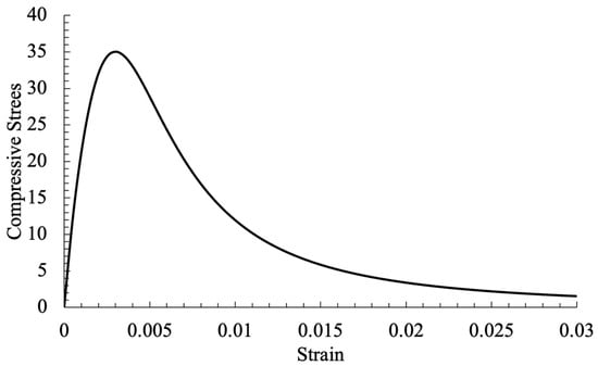
Figure 6.
Concrete’s compressive response to stress and strain.
The values in Equation (5) were obtained from the study of Hu and Schnobrich [48]. Hsu and Hsu [49] proposed a stress and strain correlation equation, where n in Equation (7) is unity once unless :
The tensile strength is simulated using a basic tension stiffening model. Figure 7 depicts a linear softening model representing the tension behavior following failure. The fracture energy , indicated by the region beneath the curve, is used in the stress–fracture energy approach to calculate the tension-stiffening reaction. To estimate and for concrete under uniaxial tension, the following formulae can be used.
where and represent the tensile strength and strain of concrete under uniaxial tension, respectively; denotes the fracture energy needed to generate a crack without any applied stress across a specific area; and, in the fracture energy formula given by Bažant and Becq-Giraudon [50], represents the maximum size of the aggregate, taking a default value of 20 mm.
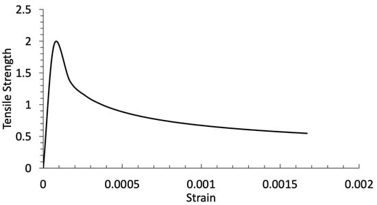
Figure 7.
Concrete’s tension response to stress and strain.
To assess the damage plasticity of concrete, the compression-induced nonlinear characteristics exhibited by concrete can be effectively conducted by incorporating the theory of damage, plasticity, or both, as suggested by Maekawa, et al. [51]. Damage refers to the reduction in elastic constants, while plasticity refers to the permanent deformation. To accurately represent the nonlinear characteristics of concrete, we integrate the notions of damage and plasticity, as demonstrated in previous research [51]. In this study, the concrete damage plasticity model is employed to simulate RC beams. In order to effectively represent the nonelastic properties of concrete, the ABAQUS software utilizes a combination of isotropic damage, tensile plasticity, and compressive plasticity [52]. The underlying assumption of this approach is that the key factors contributing to concrete failure are the formation of tensile cracks and the occurrence of compressive crushing. A concise explanation of the damage model for the concrete is provided in the ABAQUS software guide [52]; specifically, it focuses on the yield criterion, the damage variable, flow rule, and viscosity parameter.
We assume that damage within the concrete does not exist until the applied stress reaches the concrete ultimate strength . Beyond this threshold, the damage due to compression increases continuously in the softening branch , as mentioned by Jankowiak and Łodygowski [53]. The calculation for the compression damage is based on . To address the problem of excessive sensitivity to mesh conditions, an alternative method known as the fracture energy criterion is employed as a substitute for the traditional tensile strain. This approach involves evaluating the fracture energy as the ratio of the total external energy required to initiate cracking in the concrete per unit area. Similarly, the tension strength is assessed based on the monolithic increase tensile damage in concrete within the region of softening, and the damage is designed as .
For the yield criterion, ABAQUS uses the function with variables proposed by Lee and Fenves [54] for the concrete damage plasticity model, where represents the initial biaxial compressive yield stress divided by the initial uniaxial compressive yield stress, using the default value in ABAQUS, and represents the relative strength of concrete when subjected to equal biaxial compression compared to triaxial compression. Deviatoric plane yield surfaces, which are commonly encountered, can be expressed using varying values of . However, in all FEM simulations, a constant value of 2/3 is used for ; in the case of nonassociated plastic flow, ζ denotes a parameter that determines the eccentricity in the p–q plane. The conventional eccentricity for flow potential is assumed to be 0.1; the magnitude of the dilation angle is evaluated across various levels of confining pressure stress, which is taken as [55]; and, finally, the plastic strain tensor is enhanced by the viscosity parameter . Per the ABAQUS documentation, the viscosity parameter is initially set to 0. However, in cases where convergence issues arise, extensive sensitivity analyses lead to the consideration of a low viscosity coefficient (μ = 10−5) for the affected specimens, as shown in Figure 8.
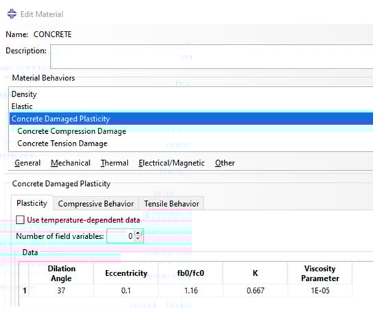
Figure 8.
Concrete damaged plasticity in ABAQUS.
The purpose of this value is to improve the rate at which convergence occurs during the phases when concrete undergoes softening and deterioration of stiffness.
3.3. FRP Properties
FRP exhibits linear elastic and orthotropic properties. As a result of its one-way nature, the behavior follows an orthotropic pattern. As the primary stress is exerted in a direction parallel to the FRP fibers, the modulus in the fiber direction is an important factor. In the FEM analysis, the experimental data are used to determine the elastic modulus in the fiber direction of the unidirectional FRP material. This material is characterized by a modulus of elasticity of 77,280 MPa, an elongation at rupture of 0.011, a tensile strength of 846 MPa, and a thickness of 1.0 mm. To streamline the research focus, we assume a perfect bond between the FRP and concrete, and the simulation of detachment is not considered. As a result of the simulation, the CFRP material is modeled as an orthotropic substance, exhibiting unique elastic moduli in three primary directions; for this, the “Engineering Constant” feature in ABAQUS is used.
Experimental measurements were conducted to determine the modulus of elasticity in the primary direction. Initially, we calculated that the modulus of resin in the remaining two orientations ( and ) is equivalent to the modulus of elasticity in the primary direction (). Based on Mosallam and Mosalam [56], a value of 1–2% for the modulus of elasticity in the primary direction is assumed for and if the experiments did not provide specific information about the resin. As CFRP experiences uniaxial tension exclusively in the direction of its fibers, the postulated parameters have no effect on its uniaxial tensile behavior.
where Poisson’s ratio is assigned variables of 0.3, 0.3, and 0.45 for , , and , respectively, and the shear moduli (, , and ) are calculated using Equation (11).
4. FEM Simulations
All numerical models involving an examination of the constituents for analysis were evaluated when fully scaled up. In the FEM, the concrete in the beams was modeled using eight-node brick elements (C3D8R). Because of the relatively thin nature of the FRP compared to the concrete section, a four-node shell element was used to model the FRP. The shell elements were directly affixed to the surface of the concrete, assuming a fully bonded interface between the concrete and FRP. To ensure consistency in element behavior and failure load, an analysis of the sensitivity of mesh convergence was conducted for every sample. A square element configuration was utilized for all specimens, and proper contact was taken between the loading plate and the concrete element. We aimed to reduce variations in element behavior and failure load by conducting a mesh convergence sensitivity analysis on every sample, attaining a square element layout for each specimen. A medium mesh configuration was chosen because it demonstrated the most appropriate deflection response and ultimate failure load, as shown in Figure 9. Of note, while maintaining the same mesh sizes for other components like reinforcement bars, the sensitivity of the RC beam to mesh density was also investigated. in Figure 9 is the applied force.
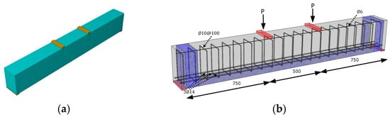
Figure 9.
View of (a) medium-size mesh for RC beam and (b) strengthened beam with CFRP at the bottom and U-anchorage (all dimensions in mm) [44].
4.1. Failure of RC Beam
This study aimed to define the failure load of the structure. To ensure a constant analysis approach for all RC beams, the risk process was chosen. Additionally, automatic stability measures were implemented to prevent any divergence in the solution. Moreover, the Nlgeom setting was initiated to consider geometric nonlinearity. By utilizing the feature for visualizing the maximum plastic strain (PE) within ABAQUS—which represents the cracking strain in the material model—we could identify the specific regions where cracks or fractures occurred. The similarity between the cracks observed in experimental tests and the correlated maximum PE values in simulations suggests that the models successfully captured the failure mechanisms of the specimens.
Similarly, Siddiqui [44] reported the failure of an RC beam with CFRP at the bottom due to concrete crushing, as demonstrated in Figure 10a. Figure 10b displays the wider and lower crack locations due to the additional FRP at U-anchorage.
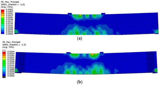
Figure 10.
An image showing the FEM’s correlated maximum PE fracture pattern for reinforced beams (a) with CFRP at the bottom and (b) with CFRP at the bottom and U-anchorage due to crushing of concrete.
To address the issue of debonding, CFRP anchors were applied on both sides of the beam. Additionally, the Finite Element Method (FEM) analysis revealed a comparable structural failure pattern occurring at the midpoint of the beam, as shown in Figure 10b, when compared with the experimental study conducted by Siddiqui [44].
4.2. Ultimate Strength Check
To demonstrate the influence of FRP on the maximum strength of RC members, Table 4 compares the ultimate failure loads of strengthened samples in terms of the experimental and FEM modeling results. Siddiqui [44] defined Scheme-1 as BS01 Specimen configuration while Scheme-2 is the same as SB07.
Table 4.
Comparison of experimental study (PEXP) conducted by Siddiqui [44] with FEM model (PFEM) in current study.
Our findings unequivocally demonstrate that the utilization of FRP increases the ultimate strength of beams substantially, as depicted in Figure 11.
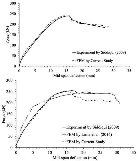
Figure 11.
Deflection under applied load (Force) for reinforced beams compared to the findings obtained by Siddiqui [44] and Lima, Doh, Hadi and Miller [16].
Nevertheless, minimal changes were observed in the strength of RC beams strengthened with CFRP in the FEM model of the current study when compared with the experimental study conducted by Siddiqui [44].
5. Findings and Discussion
Figure 12 depicts the relationships between the load and deflection of the strengthened RC beams (30 MPa concrete strength and 0.4 m2 strings used) in Group 1 (without specimen SB02 because of machine error during testing). Figure 12 compares the first six strengthening schemes (omitted SB02) with the control beam RB01. The graph demonstrates that the sheeted beams presented significant improvements in strength compared to the unsheeted control. Nevertheless, the enhancement in strength was accompanied by a decrease in deformation capacity or ductility, except for specimen SB06. Notably, for this specific specimen, the flexural capacity remained unchanged despite the minimal amount of CFRP, and the shear capacity was likewise unaffected, presenting similar characteristics to the reference specimen in terms of strength and deformation capacities. These are the principal attributes of FRP sheet-based flexural reinforcement of RC columns. Furthermore, Figure 12 shows that the 45° V-section in the web-shear zone, as demonstrated by SB03, enhanced the load-carrying capacity and achieved a lower deformation capacity.
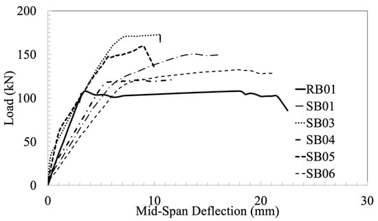
Figure 12.
Graphs of load and deflection for reference and reinforced beams (Group 1).
Table 5 presents a concise overview of the test outcomes, encompassing the ultimate load and displacement values. These results conclusively demonstrate that the implementation of CFRP sheets enhanced the load-bearing potential while limiting the ability to withstand deformation.
Table 5.
Test findings for the specimens in Group 1.
Nonetheless, employing end anchorages not only augmented the load-carrying capacity but also amplified the capacity to withstand deformation. Figure 13 displays the load–deflection relationships for five beams with concrete strength of 35 MPa, demonstrating that the beams retrofitted with CFRP strips exhibited a significant increase in strength compared to the control beam. However, the retrofitted beams also presented a reduction in deformation capacity, although the concrete strength and the amount of FRP used for the specimens in Group 2 were higher when compared to Group 1.
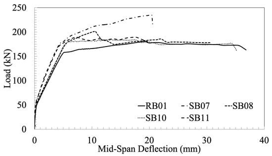
Figure 13.
Load–deflection graphs of reference and strengthened beams with CFRP (Group 2).
The failure patterns observed in the beam specimens of Group 1 are illustrated in Figure 14, Figure 15, Figure 16 and Figure 17. The failure of the reinforced beam in the absence of end anchorages was attributed to the debonding of the CFRP sheet, as depicted in Figure 17. However, the failure mode shifted to concrete crushing in the compression zone near the midpoint when debonding was prevented by employing V-wrapping at the extremities (as illustrated in Figure 14). Figure 12 illustrates in SB03 the efficacy of employing inclined strips to augment the load-bearing capacity. Similarly, SB06 presented improved deformability. Additionally, the inclination of the strips increases the load-carrying capacity further, as displayed in SB03 and SB05, while improving the deformation capacity by effectively controlling the propagation of cracks caused by diagonal tension, surpassing the performance of vertical strips (as in SB06). Shear failure appeared in SB05, as shown in Figure 16b. Moreover, debonding occurred to a greater extent with the vertical strips than with the inclined strips (see Figure 15 and Figure 17).
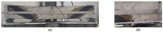
Figure 14.
Beam SB03 in Group 1: (a) view of setup after testing and (b) close view of the failure of the inclined strip.
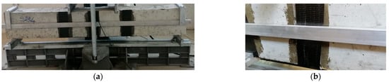
Figure 15.
Beam SB04 in Group 1: (a) view before testing and (b) close view of debonding sheets in flexural failure.
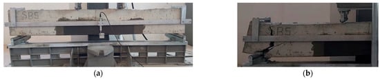
Figure 16.
Beam SB05 in Group 1: (a) view of setup before testing and (b) close view of shear failure at support after testing.
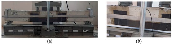
Figure 17.
Beam SB06 in Group 1: (a) view after testing and (b) close view of FRP rupture at high-stress zone.
The two primary effects of CFRP-strengthening in RC beams are an increase in strength and a decrease in deformation capacity. An overview of the test findings, containing the ultimate load values and maximum displacements, is provided in Table 6.
Table 6.
Test findings for the specimens in Group 2.
Based on the data, the beam reinforced with vertical strips (SB07)’s load capacity was significantly more than that of the control beam. As shown in the final column of Table 6, the capability to deform was reduced, as the failure took place at roughly 50% of the maximum displacement recorded in the control sample. When ultimate displacement was used to quantify the deformation capacity and load capacity, the beam reinforced with inclined CFRP strips (SB08) exhibited considerably greater capacity than the beam reinforced with half vertical strips (SB11), highlighting the superior performance of inclined CFRP strips in the middle regarding the shear strengthening of reinforced concrete beams.
Figure 18, Figure 19, Figure 20, Figure 21 and Figure 22 illustrate the typical failure schemes seen in the beam specimens from Group 2. The control specimen’s failure was attributed only to flexure, as evidenced by the development of cracks close to the midpoint that extended vertically with increasing applied stress until complete failure (see Figure 18). Furthermore, in the later phases of the loading process, evidence of concrete crushing within the midpoint, specifically in the compression area was present, as presented in Figure 18b. An important discovery was that the failure of the control specimen was caused entirely by flexural stress. The cracks started in the middle and spread in a direction approximately 45° from the horizontal as the subjected load improved until the specimen failed (refer to Figure 18b). Conversely, the failures of the reinforced beams were predominantly caused by the detachment of CFRP strips (as depicted in Figure 21b). Figure 23 compares the load–deflection relationships of two beams reinforced with GFRP using the same method but different epoxy techniques. From the figure, compared to SB13, SB12 exhibited superior strength and greater deformation capacity.
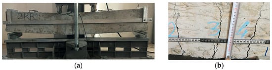
Figure 18.
Reference beam (RB) in Group 2: (a) view after testing and (b) flexural failure with cracks.
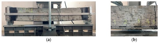
Figure 19.
Beam (SB07) in Group 2: (a) view after testing and (b) close view of flexural failure.
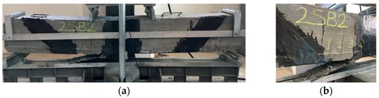
Figure 20.
Beam (SB08) in Group 2: (a) view after testing and (b) close view of debonding of CFRP.
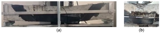
Figure 21.
Strengthened beam (SB10) in Group 2: (a) View after testing; and (b) close view of concrete crushing and debonding of CFRP.
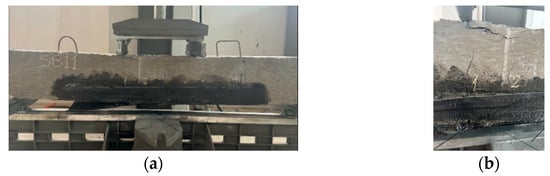
Figure 22.
Beam (SB11) in Group 2: (a) view after testing and (b) close view of concrete crushing and CFRP rupture.
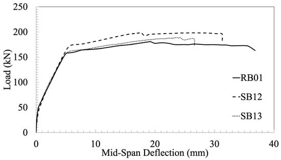
Figure 23.
GFRP-strengthened beam load–deflection graph (Group 2).
The observed failure patterns commonly seen in the Group 2 beam specimens with GFRP are illustrated in Figure 24 and Figure 25. SB12 and SB13 presented equivalent levels of concrete strength and FRP area (measuring 0.52 m2), with their primary distinction being the type of epoxy and its application. Specifically, LR300/LH300 was employed to enhance the beams using GFRP in the case of SB12, whereas Tecnobond 300 TIX was used for the same purpose in the case of SB13.
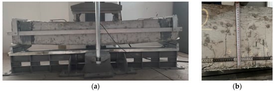
Figure 24.
GFRP-strengthened beam SB12 in Group 2: (a) view after testing and (b) close view of concrete crushing and flexural failure.
Figure 25.
GFRP-strengthened beam SB13 in Group 2: (a) view after testing and (b) close view of concrete crushing and flexural failure.
6. Conclusions
This study focused on assessing various practical techniques utilizing FRP materials to strengthen RC beams against flexure and shear failure. The results demonstrated that bonding CFRP sheets with V-shaped end anchorages on the tension side was highly effective in refining the flexural capability of RC beams in the weaker concrete strength group. Furthermore, this approach successfully maintained an adequate deformation capacity. In terms of shear strengthening, externally applied inclined CFRP strips demonstrated superior performance compared to vertically applied CFRP strips. After conducting a thorough experimental investigation, we noticed a substantial enhancement in the ultimate failure capacity of reinforced concrete beams when CFRP was employed in the flexural strengthening method in conjunction with U-shaped anchors. This strengthening method resulted in a substantial increase in strength (of around 29.8%) in the higher concrete strength group. These outcomes convincingly demonstrate the efficiency of FRP for the reinforcement of mechanical components.
Consequently, these findings can be considered a valuable contribution to the continuous advancement and exploration of innovative techniques to enhance the strength and performance of reinforced concrete structures. The specimens strengthened with inclined strips exhibited enhanced deformation and shear capacity compared to those strengthened with vertical strips. Moreover, the carbon fiber reinforced polymer (CFRP) strips that are angled were more effective in preventing crack propagation than the vertical CFRP strips.
Author Contributions
Conceptualization, M.E.U. and Y.G.; methodology, E.A.; software, M.E.U.; validation, M.E.U.; formal analysis, M.E.U. and Y.G.; investigation, E.A.; resources, E.A.; maintaining data, E.A.; writing—original draft preparation, M.E.U.; writing—review and editing, M.E.U.; visualization, M.E.U.; supervision, M.E.U.; project administration, M.E.U. and Y.G.; funding acquisition, M.E.U., Y.G. and E.A. All authors have read and agreed to the published version of the manuscript.
Funding
This study was financially supported by The Scientific and Technological Research Council of Türkiye (TÜBİTAK; Grant number: 123M231) and Scientific Research Project at Aydin Adnan Menderes University (BAP: MF-20014).
Data Availability Statement
The data included in this research are accessible upon request from the respective author handling correspondence. They are not accessible to the public owing to the Scientific Research Project Policy at The Scientific and Technological Research Council of Türkiye.
Acknowledgments
The authors express their gratitude to Ayhan Oner Yucel and Mustafa Furkan Guler from the Faculty of Engineering at Aydin Adnan Menderes University for their invaluable contributions in enhancing this study. Their expertise was instrumental in the sample preparation and testing processes.
Conflicts of Interest
The authors declare no conflicts of interest.
References
- ACI Committee 440. Guide for the Design and Construction of Externally Bonded FRP Systems for Strengthening Concrete Structures (ACI 440.2R-08); American Concrete Institute: Farmington Hills, MI, USA, 2008. [Google Scholar]
- Hollaway, L.C.; Head, P.R. Preface. In Advanced Polymer Composites and Polymers in the Civil Infrastructure; Hollaway, L.C., Head, P.R., Eds.; Elsevier Science Ltd.: Oxford, UK, 2001; p. 316. [Google Scholar]
- Teng, J.G.; Chen, J.-F.; Smith, S.; Lam, L.; Jessop, T. Behaviour and strength of FRP-strengthened RC structures: A state-of-the-art review. Proc. Inst. Civ. Eng. Struct. Build. 2003, 156, 334–335. [Google Scholar] [CrossRef]
- Teng, J.G.; Chen, J.F.; Smith, S.T.; Lam, L. FRP: Strengthened RC Structures; John Wiley & Sons: West Sussex, UK, 2002; p. 266. [Google Scholar]
- Tumialan, G.; Nanni, A.; Tim, I.; Fukuyama, H. FRP composites for strengthening civil infrastructure around the world. SAMPE J. 2002, 38, 9–15. [Google Scholar]
- Zhang, Z.; Hsu, C.-T.T. Shear Strengthening of Reinforced Concrete Beams Using Carbon-Fiber-Reinforced Polymer Laminates. J. Compos. Constr. 2005, 9, 158–169. [Google Scholar] [CrossRef]
- Zhang, Z.; Hsu, C.-T.T.; Moren, J. Shear Strengthening of Reinforced Concrete Deep Beams Using Carbon Fiber Reinforced Polymer Laminates. J. Compos. Constr. 2004, 8, 403–414. [Google Scholar] [CrossRef]
- Zhao, X.-L.; Zhang, L. State-of-the-art review on FRP strengthened steel structures. Eng. Struct. 2007, 29, 1808–1823. [Google Scholar] [CrossRef]
- Thanoon, W.A.; Jaafar, M.S.; Kadir, M.R.A.; Noorzaei, J. Repair and structural performance of initially cracked reinforced concrete slabs. Constr. Build. Mater. 2005, 19, 595–603. [Google Scholar] [CrossRef]
- Spadea, G.; Bencardino, F.; Swamy, R.N. Structural Behavior of Composite RC Beams with Externally Bonded CFRP. J. Compos. Constr. 1998, 2, 132–137. [Google Scholar] [CrossRef]
- Rahimi, H.; Hutchinson, A. Concrete Beams Strengthened with Externally Bonded FRP Plates. J. Compos. Constr. 2001, 5, 44–56. [Google Scholar] [CrossRef]
- Pantelides, C.P.; Gergely, J.; Reaveley, L.D.; Volnyy, V.A. Retrofit of RC Bridge Pier with CFRP Advanced Composites. J. Struct. Eng. 1999, 125, 1094–1099. [Google Scholar] [CrossRef]
- Neale, K.W. FRPs for structural rehabilitation: A survey of recent progress. Prog. Struct. Eng. Mater. 2000, 2, 133–138. [Google Scholar] [CrossRef]
- Napoli, A.; Bank, L.C.; Brown, V.L.; Martinelli, E.; Matta, F.; Realfonzo, R. Analysis and design of RC structures strengthened with mechanically fastened FRP laminates: A review. Compos. Part B Eng. 2013, 55, 386–399. [Google Scholar] [CrossRef]
- Nanni, A. North American design guidelines for concrete reinforcement and strengthening using FRP: Principles, applications and unresolved issues. Constr. Build. Mater. 2003, 17, 439–446. [Google Scholar] [CrossRef]
- Lima, M.M.; Doh, J.-H.; Hadi, M.N.S.; Miller, D. The effects of CFRP orientation on the strengthening of reinforced concrete structures. Struct. Des. Tall Spec. Build. 2016, 25, 759–784. [Google Scholar] [CrossRef]
- Kim, H.; Lee, K.H.; Lee, Y.H.; Lee, J. Axial behavior of concrete-filled carbon fiber-reinforced polymer composite columns. Struct. Des. Tall Spec. Build. 2012, 21, 178–193. [Google Scholar] [CrossRef]
- ISIS. Retrofitting Concrete Structures with Fiber Reinforced Polymers; ISIS: Kingston, ON, Canada, 2001. [Google Scholar]
- FIB14. Externally Bonded FRP Reinforcement for RC Structures; International Federation for Structural Concrete: Lausanne, Switzerland, 2001; p. 138. [Google Scholar]
- Maruyama, K. Recommendations for Upgrading of Concrete Structures with Use of Continuous Fiber Sheets; Research Committee on Upgrading of Concrete Structures with Use of Continuous Fiber Sheets, Japan Society of Civil Engineers: Tokyo, Japan, 2001. [Google Scholar]
- Arya, C.; Clarke, J.L.; Kay, E.A.; O’Regan, P.D. TR 55: Design Guidance for Strengthening Concrete Structures Using Fibre Composite Materials—A Review. In Structural Engineering, Mechanics and Computation; Zingoni, A., Ed.; Elsevier Science: Oxford, UK, 2001; pp. 1243–1250. [Google Scholar]
- Almusallam, T.; Al-Salloum, Y.; Alsayed, S. Fibre-reinforced polymer repair materials—Some facts. In Proceedings of the Institution of Civil Engineers-Civil Engineering; Thomas Telford Ltd.: London, UK, 2000; Volume 138, pp. 131–134. [Google Scholar]
- Clarke, J. Strengthening concrete structures with fibre composites. Proc. ICE Struct. Build. 2003, 156, 49–50. [Google Scholar] [CrossRef]
- Meneghetti, L.C.; Garcez, M.R.; da Silva Filho, L.C.P.; Gastal, F.d.P.S.L.; Bittencourt, T.N. Fatigue life of RC beams strengthened with FRP systems. Struct. Concr. 2014, 15, 219–228. [Google Scholar] [CrossRef]
- Obaidat, Y.T.; Heyden, S.; Dahlblom, O. The effect of CFRP and CFRP/concrete interface models when modelling retrofitted RC beams with FEM. Compos. Struct. 2010, 92, 1391–1398. [Google Scholar] [CrossRef]
- Bakis, C.E.; Bank, L.C.; Brown, V.L.; Cosenza, E.; Davalos, J.F.; Lesko, J.J.; Machida, A.; Rizkalla, S.H.; Triantafillou, T.C. Fiber-Reinforced Polymer Composites for Construction—State-of-the-Art Review. J. Compos. Constr. 2002, 6, 73–87. [Google Scholar] [CrossRef]
- Chin, S.C.; Shafiq, N.; Nuruddin, M.F. FRP as strengthening material for Reinforced Concrete beams with openings—A review. KSCE J. Civ. Eng. 2015, 19, 213–219. [Google Scholar] [CrossRef]
- Pendhari, S.S.; Kant, T.; Desai, Y.M. Application of polymer composites in civil construction: A general review. Compos. Struct. 2008, 84, 114–124. [Google Scholar] [CrossRef]
- Smith, S.T.; Teng, J.G. FRP-strengthened RC beams. I: Review of debonding strength models. Eng. Struct. 2002, 24, 385–395. [Google Scholar] [CrossRef]
- Al-khreisat, A.; Abdel-Jaber, M.T.; Ashteyat, A. Shear Strengthening and Repairing of Reinforced Concrete Deep Beams Damaged by Heat Using NSM–CFRP Ropes. Fibers 2023, 11, 35. [Google Scholar]
- Amaireh, L.K.; Al-Tamimi, A. Optimum Configuration of CFRP Composites for Strengthening of Reinforced Concrete Beams Considering the Contact Constraint. Procedia Manuf. 2020, 44, 350–357. [Google Scholar] [CrossRef]
- Askar, M.K.; Hassan, A.F.; Al-Kamaki, Y.S.S. Flexural and shear strengthening of reinforced concrete beams using FRP composites: A state of the art. Case Stud. Constr. Mater. 2022, 17, e01189. [Google Scholar] [CrossRef]
- Altin, S.; Anil, Ö.; Ocakli, R.Ö.; Kopraman, Y. Retrofitting of shear damaged RC beams using diagonal CFRP strips. J. Reinf. Plast. Compos. 2011, 30, 1495–1507. [Google Scholar] [CrossRef]
- Grace, N.; Sayed, G.; Soliman, A.; Saleh, K. Strengthening Reinforced Concrete Beams Using Fiber Reinforced Polymer (FRP) Laminates. ACI Struct. J. 1999, 188, 865–874. [Google Scholar]
- Hong, W.-K.; Park, S.-C.; Kim, H.-C.; Kim, J.-M.; Kim, S.-I.; Lee, S.-G. Experimental study of reinforced concrete beams strengthened with a GFRP channel and CFRP sheets. Struct. Des. Tall Spec. Build. 2010, 19, 497–517. [Google Scholar] [CrossRef]
- Kim, N.; Kim, Y.; Kim, H. Experimental and analytical investigations for behaviors of RC beams strengthened with tapered CFRPs. Struct. Eng. Mech. 2015, 53, 1067–1081. [Google Scholar] [CrossRef]
- Lu, W.-Y.; Yu, H.-W.; Chen, C.-L.; Liu, S.-L.; Chen, T.-C. High-strength concrete deep beams with web openings strengthened by carbon fiber reinforced plastics. Comput. Concr. 2015, 15, 21–35. [Google Scholar] [CrossRef]
- Norris, T.; Saadatmanesh, H.; Ehsani, M.R. Shear and Flexural Strengthening of R/C Beams with Carbon Fiber Sheets. J. Struct. Eng. 1997, 123, 903–911. [Google Scholar] [CrossRef]
- Rahai, A.R.; Saberi, M.R. Experimental and numerical investigation of damaged concrete beams strengthened with FRP composed of different fibres and resins. Struct. Des. Tall Spec. Build. 2011, 20, 972–985. [Google Scholar] [CrossRef]
- Tanarslan, H.M.; Kumanlıoğlu, A.A.; Şakar, G. An anticipated shear design method for reinforced concrete beams strengthened with anchoraged carbon fiber-reinforced polymer by using neural network. Struct. Des. Tall Spec. Build. 2015, 24, 19–39. [Google Scholar] [CrossRef]
- Yurdakul, Ö.; Avşar, Ö. Structural repairing of damaged reinforced concrete beam-column assemblies with CFRPs. Struct. Eng. Mech. 2015, 54, 521–543. [Google Scholar] [CrossRef]
- Hadi, M.; Widiarsa, I. Axial and Flexural Performance of Square RC Columns Wrapped with CFRP under Eccentric Loading. J. Compos. Constr. 2012, 16, 640–649. [Google Scholar] [CrossRef]
- Mohammed, B.; Lee Woen, E.; Abdul Malek, M. One way RC wall panels with openings strengthened with CFRP. Constr. Build. Mater. 2013, 40, 575–583. [Google Scholar] [CrossRef]
- Siddiqui, N. Experimental investigation of RC beams strengthened with externally bonded FRP composites. Lat. Am. J. Solids Struct. 2009, 6, 343–362. [Google Scholar]
- Smith, S.T.; Kim, S.J. Strengthening of one-way spanning RC slabs with cutouts using FRP composites. Constr. Build. Mater. 2009, 23, 1578–1590. [Google Scholar] [CrossRef]
- AS3600. Concrete Structures; SAI Global Limited: Sydney, Australia, 2009. [Google Scholar]
- Saenz, L.P. Discussion of “Equation for the Stress-Strain Curve of Concrete” by Desayi and Krishnan. J. Am. Concr. Inst. 1964, 61, 1229–1235. [Google Scholar]
- Hu, H.T.; Schnobrich, W.C. Constitutive Modeling of Concrete by Using Nonassociated Plasticity. J. Mater. Civ. Eng. 1989, 1, 199–216. [Google Scholar] [CrossRef]
- Hsu, L.S.; Hsu, C.-T.T. Complete stress—Strain behaviour of high-strength concrete under compression. Mag. Concr. Res. 1994, 46, 301–312. [Google Scholar] [CrossRef]
- Bažant, Z.P.; Becq-Giraudon, E. Statistical prediction of fracture parameters of concrete and implications for choice of testing standard. Cem. Concr. Res. 2002, 32, 529–556. [Google Scholar] [CrossRef]
- Maekawa, K.; Pimanmas, A.; Okamura, H. Non-Linear Mechanics of Reinforced Concrete; Spon Press: New York, NY, USA, 2003. [Google Scholar]
- Hibbitt, K. Sorensen. In ABAQUS/CAE User’s Manual; Hibbitt, Karlsson & Sorensen, Incorporated, Pennsylvania State University: State College, PA, USA, 2002. [Google Scholar]
- Jankowiak, T.; Łodygowski, T. Identification of parameters of concrete damage plasticity constitutive model. Found. Civ. Environ. Eng. 2005, 6, 53–69. [Google Scholar]
- Lee, J.; Fenves, G.L. Plastic-Damage Model for Cyclic Loading of Concrete Structures. J. Eng. Mech. 1998, 124, 892–900. [Google Scholar] [CrossRef]
- Majewski, T.; Bobinski, J.; Tejchman, J. FE analysis of failure behaviour of reinforced concrete columns under eccentric compression. Eng. Struct. 2008, 30, 300–317. [Google Scholar] [CrossRef]
- Mosallam, A.S.; Mosalam, K.M. Strengthening of two-way concrete slabs with FRP composite laminates. Constr. Build. Mater. 2003, 17, 43–54. [Google Scholar] [CrossRef]
Disclaimer/Publisher’s Note: The statements, opinions and data contained in all publications are solely those of the individual author(s) and contributor(s) and not of MDPI and/or the editor(s). MDPI and/or the editor(s) disclaim responsibility for any injury to people or property resulting from any ideas, methods, instructions or products referred to in the content. |
© 2023 by the authors. Licensee MDPI, Basel, Switzerland. This article is an open access article distributed under the terms and conditions of the Creative Commons Attribution (CC BY) license (https://creativecommons.org/licenses/by/4.0/).