Article

Fire Resistance of Prestressed Multispan Steel Truss Composite Slab

1
College of Civil Engineering, Shandong Jianzhu University, Jinan 250101, China
2
Key Laboratory of Building Structural Retrofitting and Underground Space Engineering, Shandong Jianzhu University, Ministry of Education, Jinan 250101, China
*
Authors to whom correspondence should be addressed.
Buildings 2024, 14(1), 80; https://doi.org/10.3390/buildings14010080
Submission received: 7 November 2023 / Revised: 14 December 2023 / Accepted: 25 December 2023 / Published: 27 December 2023
(This article belongs to the Section Building Structures)

Abstract

:
Prestressed steel truss composite slab is composed of a precast prestressed bottom slab, a steel truss, and a postcast concrete layer. In order to investigate the fire resistance performance of prestressed multispan steel truss composite (STPC) slabs under the coupled effect of high temperature and load, four specimens of such composite slab containing two spans with various postcast concrete layer thicknesses were fabricated. Fire experiments were conducted following the ISO 834 standard temperature–time curve. Two of the specimens underwent two-span fire experiments, while the other two underwent single-span fire experiments. During the experiment, the bottom of the multispan STPC slabs exhibited serious bursting under fire and the precast concrete layer at the bursting locations fell off. The experiment result showed that the degree of bursting was much higher than that of nonprestressed composite slabs and single-span slabs. Although bond failure was observed at the composite interface where horizontal cracks developed, the STPC slabs still performed well in terms of load bearing, which could be attributed to the contribution of the steel truss. Under the coupled action of high temperature and load, concrete cracks were prone to occurring at the cut-off position of the top reinforcement near the supports; therefore, the anchorage length of these reinforcing bars should be appropriately extended. The damage to the STPC slab specimens after fire was found to be more serious for those with a less-think postcast concrete layer. In the single-span fire experiments, the structural performance of the unfired span was not prominently affected. Due to the bursting of the precast layer, the thickness of the STPC slabs was reduced, resulting in decreases in the thermal insulation and the fire resistance limit. The fire resistance limits of the STPC slabs with 60 mm and 80 mm postcast concrete layers were 90 min and 130 min, respectively. When a high fire resistance limit of the STPC slabs is required in a design, it is recommended that the thickness of the postcast concrete layer be no less than 60 mm.

1. Introduction

Structural composite slabs normally consist of two layers of concrete, the lower layer being a precast prestressed concrete slab with a steel truss (see Figure 1) and the upper layer being a postcast composite concrete slab. The steel truss not only ensures the co-work of the precast and postcast composite concrete layers but also changes the force mechanism of the precast bottom slab and improves the mechanical performance of the precast slab. By using the prestressing technique, a thinner precast bottom slab, which has stronger cracking resistance than normal composite slabs, can be achieved.
Authors [1] examined the stiffness of STC slabs with different sizes through finite element analysis and showed that the short-term stiffness of STC slabs is higher than that of ordinary composite slabs. A method for calculating the short-term stiffness of four types of STC slabs with different sizes was also proposed. By conducting four-point bending tests, researchers [2] investigated the mechanical behaviors of a rebar truss ribbed slab that incorporated shuttering and showed that the interaction between the steel profiles and the concrete improved both the bending resistance and the ductility of the slab. Researchers [3] parametrically investigated the effect of recycled coarse aggregate (RAC) on the long-term deflection of steel truss slabs, based on which a design method was proposed. Authors [4] quantitatively analyzed the contribution of the truss framework to the load-carrying capacity of the bottom layer of a composite slab. The results showed that, for a common STC slab in China with a 60 mm bottom precast layer and a 70 mm postcast concrete layer, which are considerably less thick than the commonly used composite slabs in Japan and Germany, the truss framework could enhance the load-carrying capacity of the sections subjected to negative bending moments. In reference [5], two rebar truss composite slabs without temporary supports were tested to evaluate their deflections, the stresses of the truss framework, as well as the ultimate load-carrying capacities of the slabs. Through finite element analysis, authors [6,7] have discussed the effects of various influencing factors on the short-term stiffness of self-supporting rebar truss concrete composite slabs, and another paper [8] proposes a calculation method for the short-term stiffness of prestressed steel truss bottom slabs.
Building fires occur frequently, causing economic losses that are second only to those of droughts and floods. International attention has been paid to the study of structural fire resistance since the 1950s. During the spread of fires, the floor often is one of the most severely damaged components. The authors in [9] conducted an in-depth study on the behavior of single-span cantilever-supported laminated slabs at both ends under different fire scenarios by considering both the heating and cooling phases of the fire. By comparing the results of the fire experiment and an ABAQUS finite element analysis, Refs. [10,11] have carried out parametric analyses of the factors affecting the fire resistance of prestressed single-span composite slabs. Then, Refs. [12,13,14,15] have carried out studies on laminated slabs with different restraining conditions, indicating that the type of in-face restraint has a significant effect on the fire resistance performance of the slabs. The deflection response of simply supported slabs in the heating stage shows ductility, while in-face-restrained slabs tend to be rigid. The presence of steel trusses not only enables the precast layer and the postcast layer to work better together but also improves the deformation capacity of the stacked slabs. Fire experiments and static postfire load experiments with 12 prestressed composite slabs were carried out [16], and fire resistance experiments were carried out with three two-way constrained precast concrete composite slabs with different load levels and constraints [17]. A comparative study showed that the steel truss plays an important role in the fire resistance of composite slabs. In [18,19], a failure assessment model is proposed for unconstrained, simply supported, lightweight reinforced concrete slabs under fire. Moreover, Refs. [20,21,22,23] have studied the influence of different factors on the residual bearing capacity of multispan continuous cast-in-place concrete slabs after fire, showing that concrete spalling, reinforcement ratio, and steel bar layout have significant effects on the ultimate load and failure mode of fire-damaged continuous slabs. The authors proposed an elliptic method that can accurately compute the residual ultimate load of continuous fire-damaged slabs with a large span-to-thickness ratio. The effect of the number of heating compartments on the fire resistance of continuous multispan slabs was investigated [24], showing that the fire scenario of the edge compartments is an important factor determining the deflection trend (upward or downward) of the heated intermediate compartments of the same continuous floor slab. In refs. [25,26], experimental studies were conducted on the mechanical properties of continuous concrete slabs under the action of fire, and the mechanical behavior of postfire slab cracks, deformation, concrete, reinforcement strains, and postfire damage modes was obtained, showing that the location and number of fire-exposed spans had an important influence on the distribution of cracks at the top (or bottom) of each span of the experimental slab.
The existing literature has mostly examined the mechanical properties of composite slabs at room temperature and the fire resistance of single-span composite slabs. The research on the fire resistance of multispan continuous slabs has mainly focusd on cast-in-place slabs, while in practical engineering, the STPC slabs are mostly multispan continuous slabs, and there are few experimental studies on the fire resistance of multispan prestressed continuous composite slabs. So, in this study, we designed and fabricated four experimental specimens of two-span prestressed continuous steel truss composite slabs, which had different thicknesses of the postcast layer, and, respectively, carried out a one-span and a two-span fire resistance experiment to research the fire resistance performance of multispan composite slabs with different postcast layer thicknesses in the case of single- and multispan fires.

2. Materials and Methods

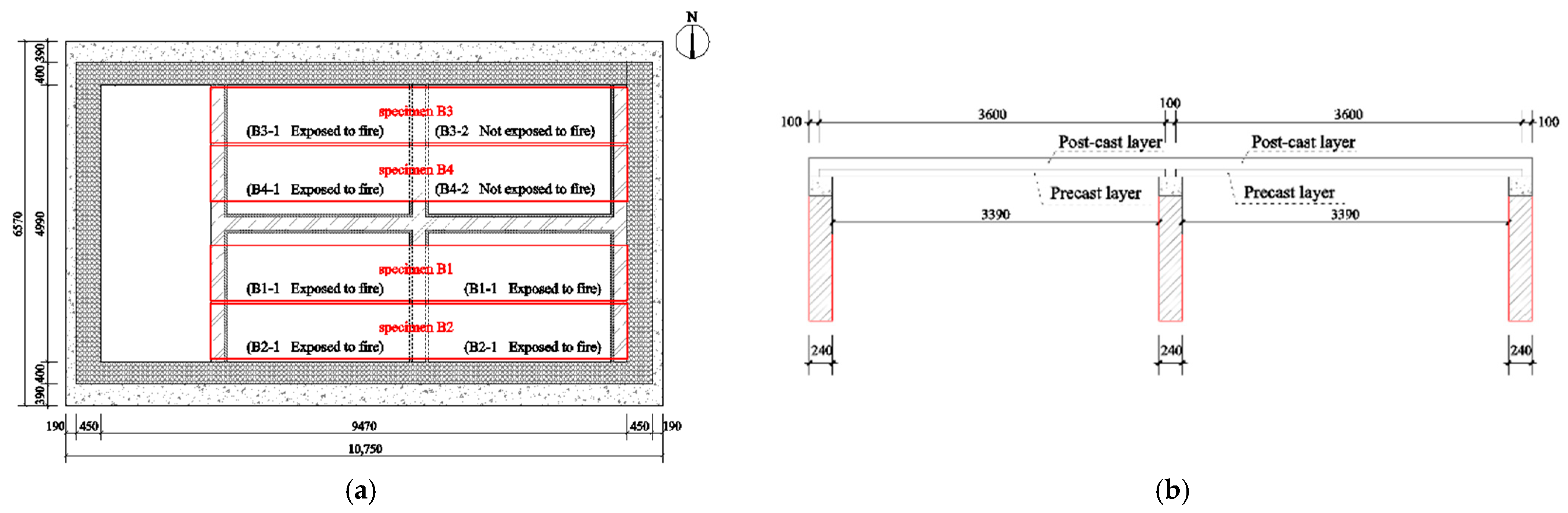
2.1. Specimen Design

Four two-span STPC slab specimens were designed and fabricated for experiments. The overall plane size of the specimens was 7500 mm × 1000 mm, and the clear span length was 3390 mm. Each specimen had two precast concrete bottom slabs, which were manufactured in batches in a factory. The plan dimension of a single precast concrete bottom slab was 3600 mm × 1000 mm, and its thickness was 40 mm. Moreover, the longitudinal reinforcing bars with a concrete cover of 20 mm protruded out of the precast concrete bottom slab at two ends, and two longitudinal steel trusses were installed on top of the precast concrete bottom slab (see Figure 2). Slab top reinforcement of 10 mm diameter bars with a length of 2400 mm and a 100 mm spacing was placed at the position of the supports in the middle of the composite slab. The postcast concrete layer thickness of specimens B1 and B3 was 60 mm, while the postcast concrete layer thickness of specimens B2 and B4 was 80 mm.

2.2. Material Properties

The designed concrete strength grade for the precast bottom slab was C40, the strength grade for the postcast layer was C30, and the compressive strength of the concrete cubes was 52.9 MPa and 32.3 MPa, respectively. The reinforcement at the bottom of the concrete slab was made of spiral-ribbed steel wires of AH 4.8, where “AH” represents a high-strength spiral rib steel wire material, and 4.8 indicates a tensile strength of 4.8 megapascals (MPa). They were prestress-eliminated, which is a steel treatment method that reduces or eliminates internal stress in steel by applying appropriate heat treatment or tensile stress release. This treatment can improve the reliability and durability of steel, making it more suitable for use in civil engineering structures and components. The steel bar at the top of the slab at the midspan support of the composite slab was an HRB400 steel bar with a diameter of 10 mm, the steel bar truss support bar was Φb5 cold-drawn low carbon steel wire, and the support longitudinal bar was an HRB400 steel bar with a diameter of 8 mm. The measured tensile ultimate strengths were 1589 N/mm2, 574 N/mm2, 599 N/mm2, and 503 N/mm2, respectively.

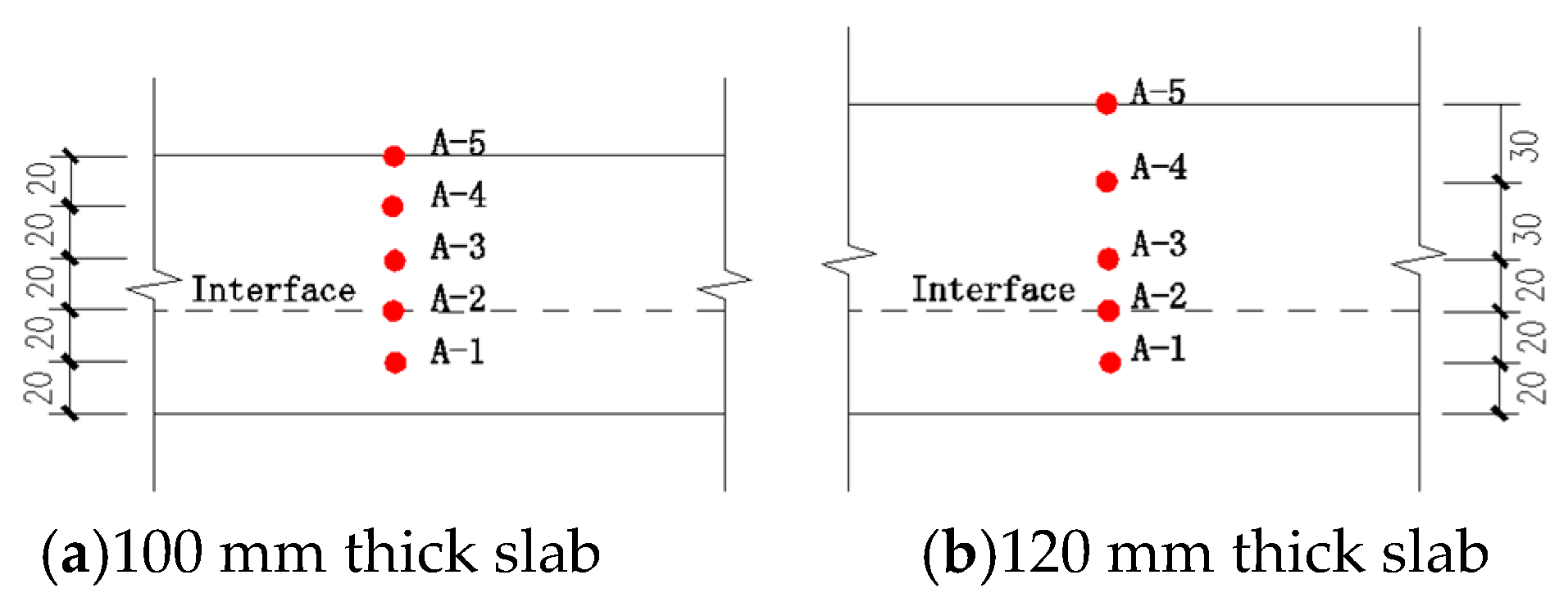
2.3. Arrangement of Measurement Points

The temperature at various locations within the specimen and inside the furnace during the experiment process was measured using either a nickel–chromium/nickel–silicon (K-type) thermocouple or a platinum–rhodium (S-type) thermocouple as a temperature sensor. The deformation of every specimen was measured using a differential variable reluctance transducer (LVDT) positioned on the surface of it.
Four thermocouples were arranged in each furnace to measure the temperature in the furnace chamber during the experiment. Two of them were connected to the acquisition instrument and two were connected to the control system. Four control sections were selected for each burning span of each specimen to measure the concrete temperature of the specimen and the temperature of the corresponding location of the reinforcement, respectively designated as A–H and GJA–GJH, as shown in Figure 3a. Displacement measurement points were arranged at the supports, midspan, and at the quarter points on the precast slab, respectively designated as 1–9, as shown in Figure 3b. Each temperature experiment control section was arranged along the height of the slab section with five concrete measuring point thermocouples and two steel measuring point thermocouples. The temperature measurement points on each control section had the same distance from the bottom of the slab, considering the thickness of the slab. Figure 4 shows the layout of the concrete temperature measurement points for control section A. The temperature measurement points for the reinforcing steel were arranged on the upper chord and lower chord of the steel truss, corresponding to distances of 80 mm and 20 mm from the bottom of the slab, respectively. The temperature measurement point on the upper chord of the steel truss for control section A was recorded as GJA2, while the temperature measurement point on the lower chord of the truss was recorded as GJA1. The same naming convention was applied for the other sections. Since the lower longitudinal reinforcement of the truss was in the same horizontal plane as the prestressed reinforcement, the thermocouple arranged in the lower chord could also be considered as the temperature measuring point of the prestressed reinforcement.

2.4. Fire Experiment Design

The fire resistance experiment was carried out with a horizontal combustion furnace, which was modified to accommodate the specimen dimensions. The experiment was conducted in two phases: the first phase involved a two-span constant load and temperature-rise fire performance experiment on specimens B1 and B2, while the second phase involved a single-span constant load and temperature-rise fire performance experiment on specimens B3 and B4. In other words, the composite slabs with different thicknesses of the postcast layer were subjected to single-span and two-span fire resistance experiments, respectively. The plan layout of the specimens in the furnace is shown in Figure 5. According to the functional requirements of general buildings and the specifications of the composite slab in this experiment, a uniform constant load of 2.0 kN/m2 was initially applied to the standard cast iron block before the experiment, as shown in Figure 6. Under the load-holding condition, the heating was carried out according to the ISO 834 standard heating curve [27] to simulate the fire behavior of the multispan prestressed steel truss composite slab, until the specimens reached the fire-resistance limit, and then the experiment was stopped. The criteria for assessing fire resistance limits mainly included the load-bearing capacity, integrity, and insulation performance of the experimental specimens. According to the load-bearing capacity criteria in Table 1, the maximum deflection and maximum bending deformation rate of the specimens did not exceed the specified limits. Based on the integrity criteria, significant deflection deformation and horizontal cracking occurred at the joint surfaces while conducting the experiment, but there was no separation between the prefabricated layer and the laminated layer, and no fire leakage occurred on the back side. Furthermore, according to the insulation judgment criteria presented in Table 2, the fire resistance limits for B1, B2, B3, and B4 slabs are 90 min, 130 min, 91 min, and 135 min, respectively [27].

3. Experiments and Analysis

In order to accurately record and clearly describe the phenomena during and after the experiments and to carry out subsequent comparative analysis, the first span of specimen B1 was recorded as slab B1-1, the second span was recorded as span B1-2, and the same was carried out for each span of other specimens, as shown in Figure 5a.

3.1. First Fire Experiment

The fire resistance experiment was conducted on specimens B1 and B2 in the two-span configuration. After around 7 min of fire exposure and at a temperature of approximately 510 °C, transverse cracks perpendicular to the spans appeared at the negative reinforcement midsupport locations on the surface of the slabs, as shown in Figure 7a. With continued burning, multiple cracks perpendicular to the direction of the slab span appeared in the upper part of the slab at the center support location in sequence. After about 21 min, popping sounds were heard at the bottom of the B2-2 spanning plate, which were followed by popping sounds at B1-2. As the experiment proceeded, a large number of water traces appeared on the surface of the slab, gathering to form a water bay; as the temperature continued to rise, the water traces on the surface of the slab formed blisters, and a large amount of water vapor appeared on the top of the slab, as shown in Figure 7b. As it continued to burn, the slab exhibited obvious deflection deformation; after burning for about 35 min, a bursting sound occurred from the prefabricated B2-1 span slab layer, and a crack appeared on the laminated surface, almost through the whole span, as shown in Figure 7c. As the slab continued to burn, cracks continued to develop, and the deflection deformation of each slab was accelerated. After being subjected to fire for 101 min, the deflection of slab B1 increased dramatically and was obviously greater than the deflection of slab B2. At the board end of each slab, there was obvious warping, the crack at the cut-off position of the negative reinforcement of the B2-1 span support obviously widened, and the whole back casting layer fractured, as shown in Figure 7d. After 142 min of fire, the deflection of the B1-2 span slab obviously increased, and the depression was serious. The experiment was terminated at 150 min by extinguishing the fire and providing ventilation to reduce the temperature.

3.2. Second Fire Experiment

The second fire resistance experiment was conducted on specimens B3 and B4 in a single-span configuration, specifically on spans B3-1 and B4-1. After exposure to fire, transverse cracks perpendicular to the spans appeared at the midsupport negative reinforcement locations on the surface of the slabs, as shown in Figure 8a, resulting in noticeable cracks that traversed the surface of spans B3-1 and B4-1. Bursting sounds were also heard from the bottom of slab B4-1. After approximately 10 min of burning, vertical cracks perpendicular to the span direction developed at the midsupport locations of spans B3 and B4, accompanied by the presence of water traces. Between approximately 12 and 23 min, bursting sounds were heard from the bottom of spans B4-1 and B3-1. At around 45 min, significant deflection and deformation were observed in span B3-1, with noticeable warping occurring at the edges of all slabs. At approximately 77 min, longitudinal cracks along the span direction developed on the surface of span B3-1, nearly spanning the entire surface, while the crack at the negative reinforcement location of span B4-1 significantly widened, resulting in complete fracture of the postcast layer, as shown in Figure 8b. At 144 min, significant deflection and severe sagging were observed on the surface of span B3-1, with noticeable variation in deformation compared to the adjacent specimens. Cracks between the slab ends and the support were observed, indicating fire leakage. At 153 min, the burning was stopped, and the experiment was concluded. Spans B3-2 and B4-2 were not exposed to fire, and no significant experimental phenomena were observed during the experiment.

3.3. Failure Mode and Analysis of Specimens

After the fire experiment, the furnace temperature was reduced to room temperature, and the load was removed to observe the damage pattern of the specimens. Both fire experiments resulted in carbonization and spalling of the bottom concrete of the exposed spans due to prolonged exposure to high temperatures, exhibiting a grayish-white appearance. The concrete at the bottom of the slab burst seriously—almost all of the precast layer concrete at the location of bursting fell off, and the prestressing reinforcement was exposed. The damage pattern of the bottom of the slab is shown in Figure 9.
The specimens in both fire experiments exhibited vertical cracks extending from the top surface to the side of the slabs, with horizontal cracks occurring at the interface. Delamination between the precast layer and the postcast layer was observed, as shown in Figure 10.
In both fire experiments, the surface of the slabs exhibited significant cracking at the exposed spans and midsupport locations. At the supports, vertical cracks were observed perpendicular to the span direction, while longitudinal cracks along the span direction developed midspan. Additionally, the top longitudinal cracks in the steel truss were wider, and the slabs with a thinner postcast layer exhibited more severe crack propagation, as shown in Figure 11. In the single-span fire experiment, no significant damage was observed in the unexposed span after the fire.
Based on a comparative analysis of references [28,29,30], the failure modes of the composite slabs in the two fire experiments were as follows:
(1)
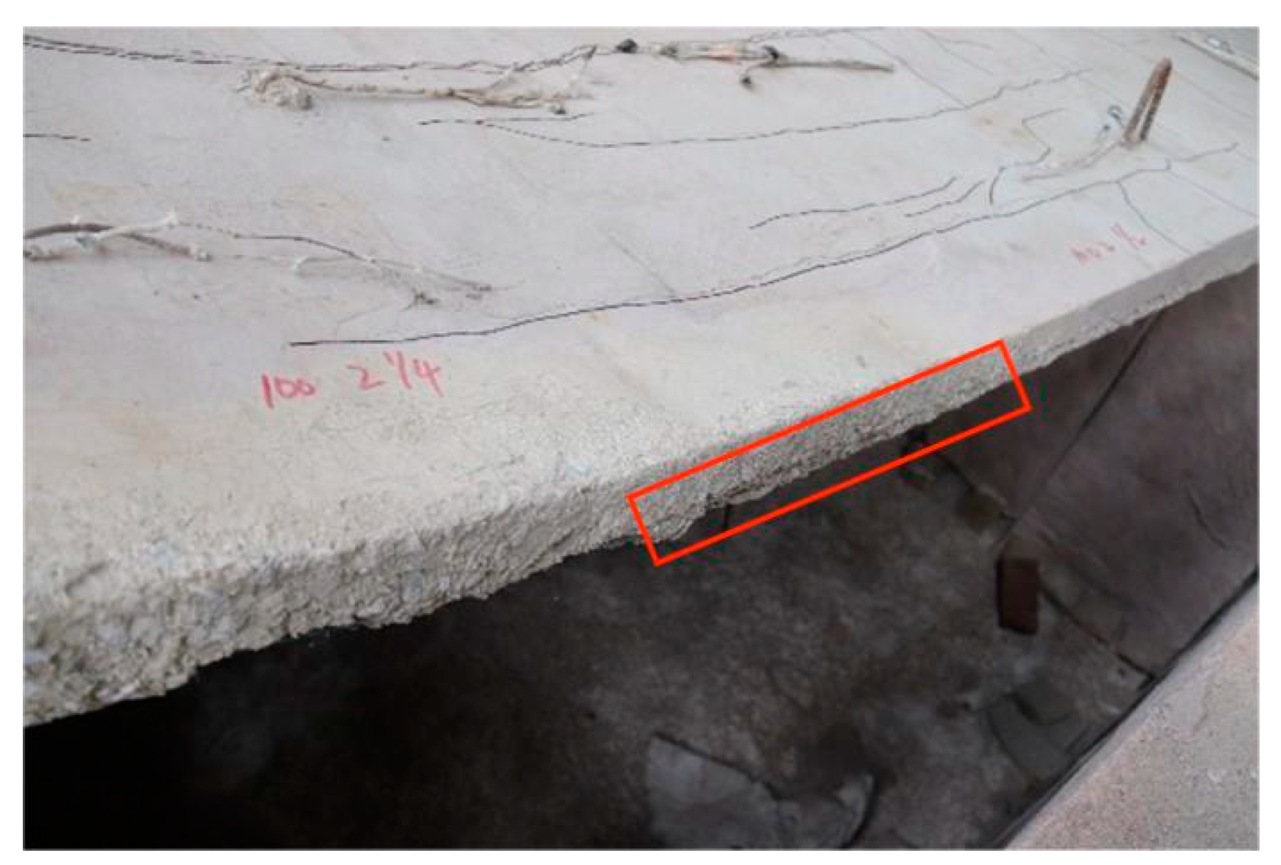
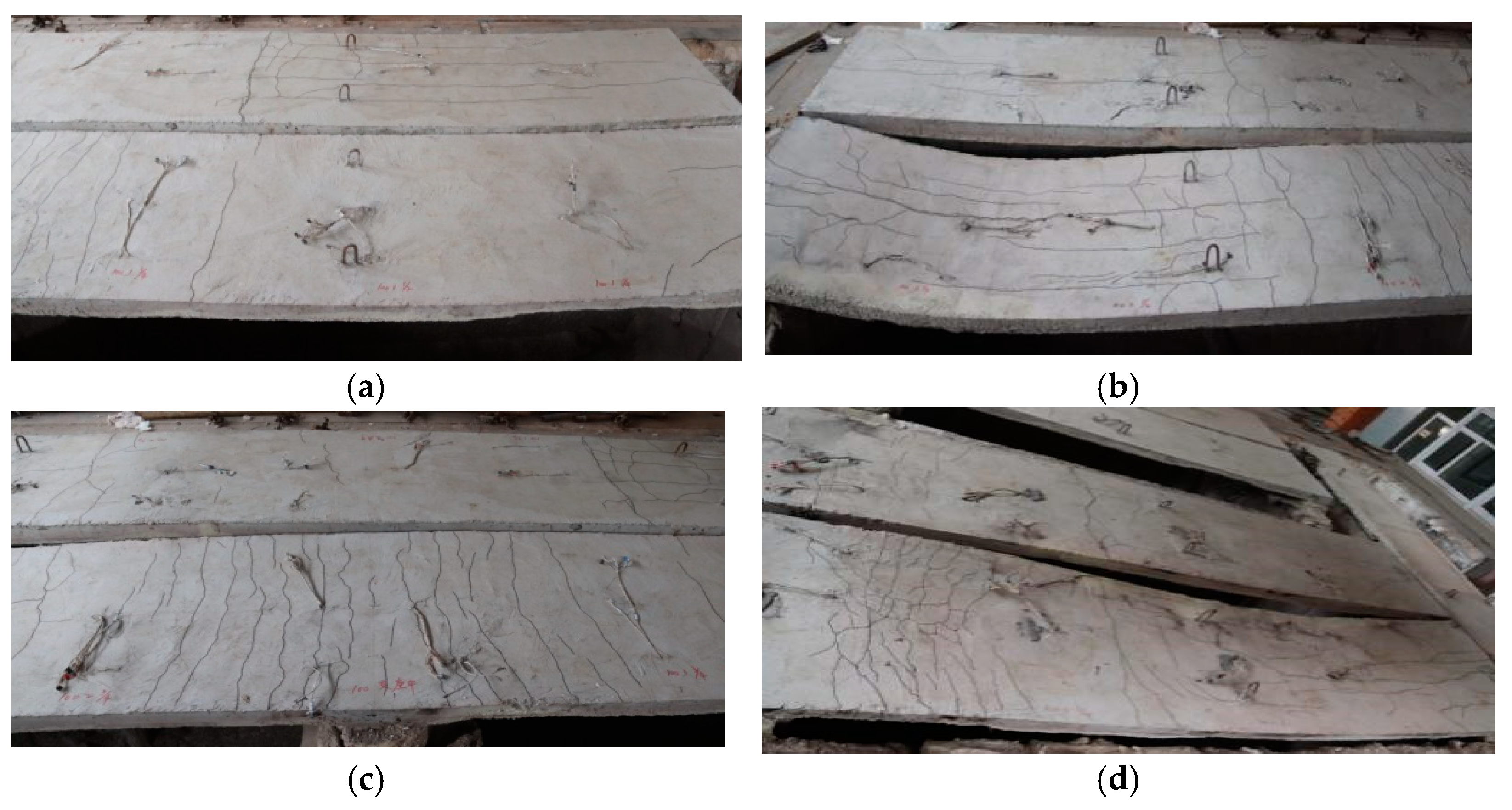
During the experiment, a transverse crack perpendicular to the span of the slab was initiated at the truncated position of the negative moment reinforcement near the upper support. At the conclusion of the experiment, this crack exhibited the maximum width, leading to the fracture of the composite layer. The primary reason behind this phenomenon was that the lower region of the slab, being closer to the heat source, experienced a greater temperature rise and underwent larger deformation due to heating. As a result, it generated tensile stress in the upper region, which experienced relatively smaller deformation, known as temperature-induced stress, caused by the temperature gradient. Under the combined action of load and temperature, the tensile zone in the upper region gradually extended outward along the span direction from the support. As a result, the negative moment reinforcement, originally situated within the compressive zone, entered the tensile zone at its truncated location. Furthermore, all of the tensile stresses in this specific position were borne by the concrete, leading to a concentration of tensile forces and initiating the initial cracking of the concrete. Consequently, the concrete experienced the initial cracking.
(2)
After the exposure to the fire event, a substantial number of cracks developed at the midspan supports of the slab during the experiment. This occurrence could be attributed to several factors. Firstly, as the temperature rose, the generated temperature-induced stress gradually intensified. Furthermore, the influence of the fire on material properties and potential cracking at the bottom of the slab led to variations in the structural stiffness along the span. This, in turn, resulted in a redistribution of internal forces, leading to an increase in the negative bending moments at the supports. Concurrently, both the crack resistance and flexural bearing capacity of the slab diminished due to the effects of load–temperature coupling. Consequently, the load-carrying capacity of the supports fell short of the required level, ultimately giving rise to transverse cracks perpendicular to the span of the slab at the support locations.
(3)
During the fire experiment, longitudinal cracks along the span direction of the slab were observed. The analysis of the reasons for this phenomenon revealed that although temperature gradients induced tensile stresses in the upper region of the slab, the presence of applied loads resulted in compressive stresses in the upper midspan region under the combined effect of load and temperature. Therefore, transverse cracks perpendicular to the span did not develop in the upper midspan region. However, along the span direction, there were tensile stresses induced by temperature gradients, leading to the formation of longitudinal cracks. Additionally, the interface between the precast and postcast layers experienced damage due to the effects of temperature. The steel truss connected the precast layer with the postcast layer, causing the expansion of the precast layer due to heating. As a result, the postcast layer was subjected to forces along the vertical span direction through the steel truss, resulting in a concentration of tensile stresses at the location of the steel truss. Therefore, wider longitudinal cracks developed in that region.
(4)
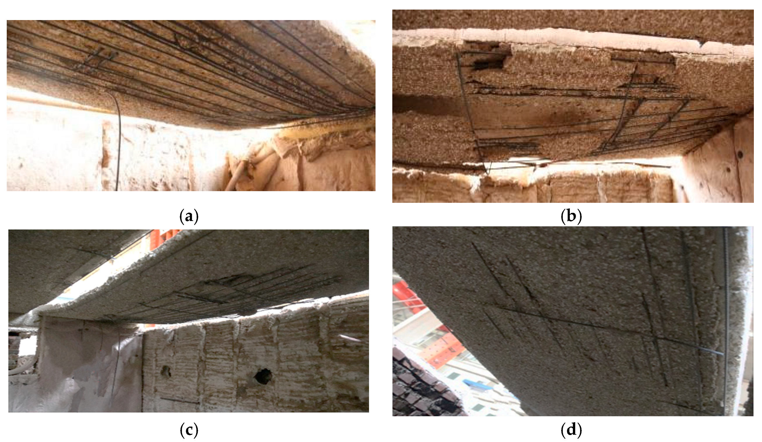
When subjected to fire, the prestressed steel truss composite slabs exhibited a tendency to experience severe spalling, often resulting in the detachment of the precast layer as a unified entity. This spalling phenomenon was more pronounced compared to non-prestressed composite slabs, fully cast prestressed slabs, and single-span prestressed steel truss reinforced composite slabs. The underlying cause could be attributed to the precompression applied, which established an initial compressive state within the precast layer. Subsequent exposure to high temperatures induced additional compressive stresses due to temperature gradients, further contributing to the risk of bond failure at the interface, leading to delamination between the precast and postcast layers. Consequently, the precast layer transformed into a slender compressed plate, making it susceptible to instability-induced spalling under the influence of high-temperature steam. In comparison to the single-span simply supported prestressed steel truss composite slabs, the multispan composite slabs experienced higher levels of temperature-induced stresses during fire due to the lateral restraint provided by the supports, exacerbating the severity of the spalling. These observations highlight the importance of considering such behavior in the design and analysis of composite structures under fire conditions.
(5)
After the fire experiments, the precast layers and the postcast layers of the composite slabs showed delamination. The reasons for this were found to be as follows: The interface between the precast layer and the postcast layer was prepared with roughening treatment, as they were not poured simultaneously, leading to a limited bond strength between the two types of concrete. Under the high-temperature exposure during the fire, the slab experienced a gradual decrease in temperature from the exposed face to the back face. This temperature gradient induced tensile stresses at the interface, generating shear stresses between the two types of concrete. Consequently, when the shear stresses exceeded the bond strength, horizontal cracks and delamination occurred between the precast layer and the postcast layer. However, the presence of the steel truss embedded in the precast layer facilitated their combined behavior, highlighting the crucial role of steel trusses in ensuring the overall integrity of the component.

4. Results

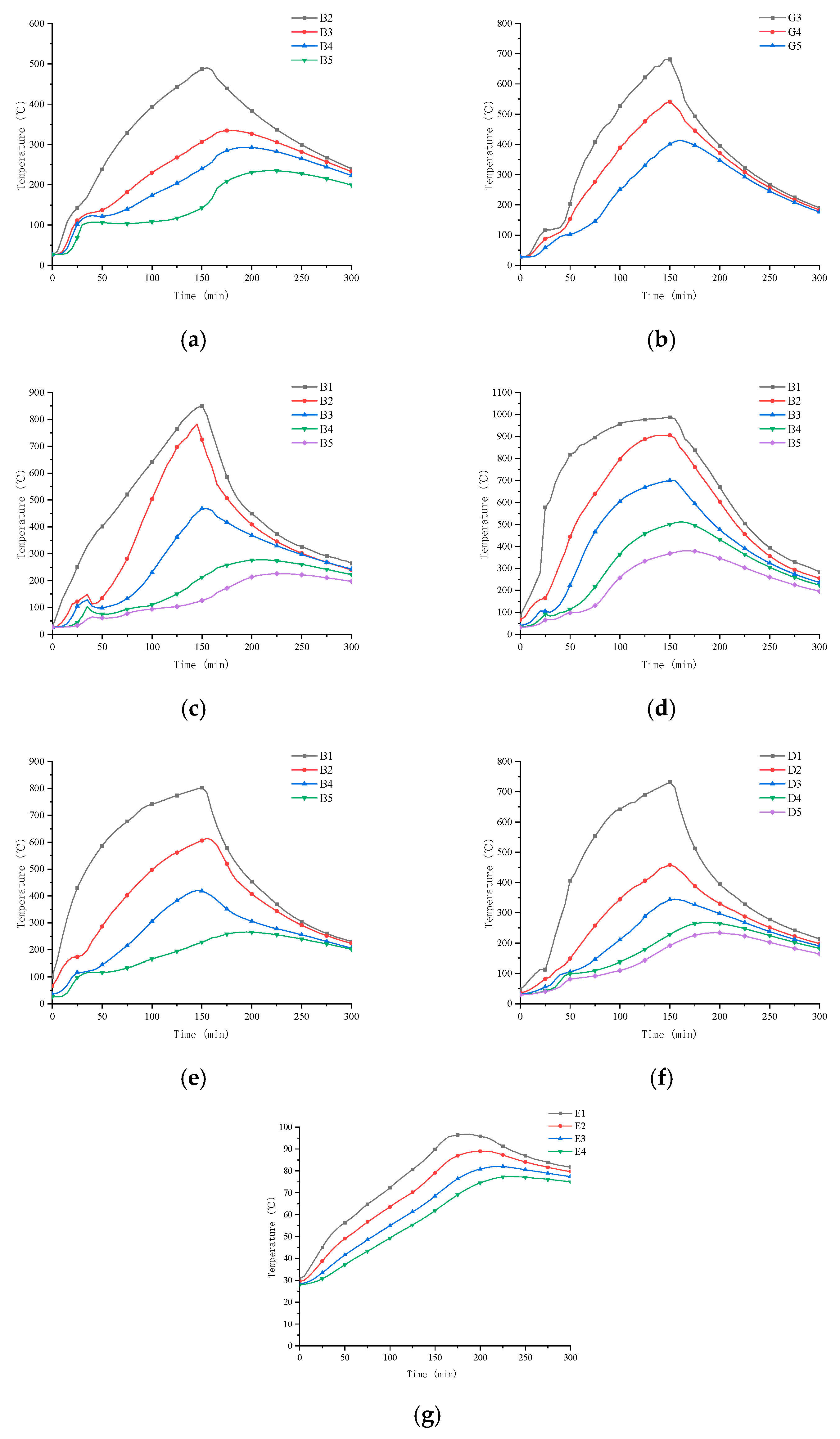
4.1. Temperature Distribution within the Furnace during Fire Resistance Experiment

The time furnace temperature collected with the S-type platinum–rhodium thermocouple was compared with the ISO 834 standard heating curve, as shown in Figure 12. The furnace temperature curves of the two fire resistance experiments were in good agreement with the ISO 834 standard heating curve, showing a rapid increase in temperature during the initial stages, simulating the occurrence of a fire and the subsequent phenomena.

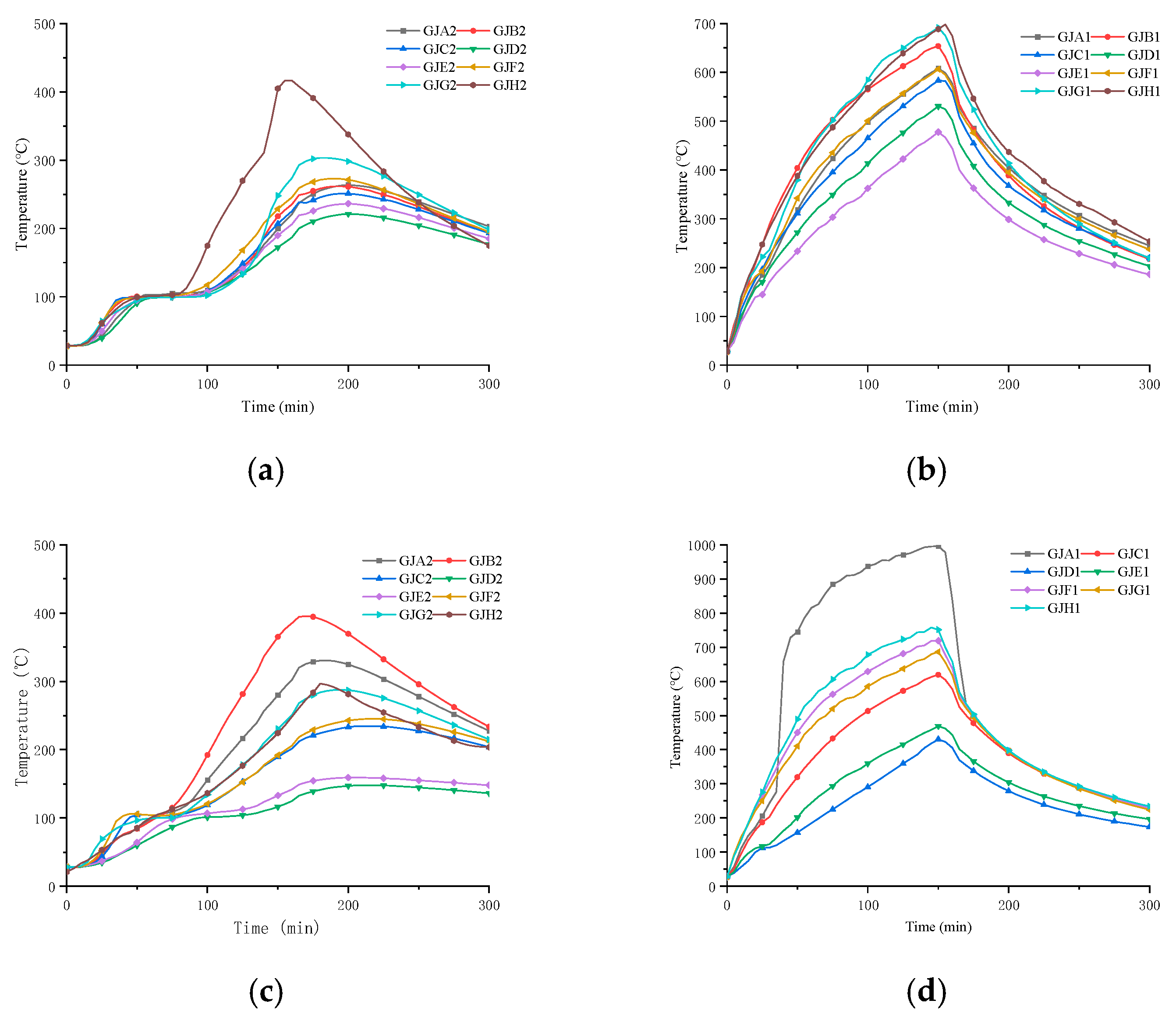
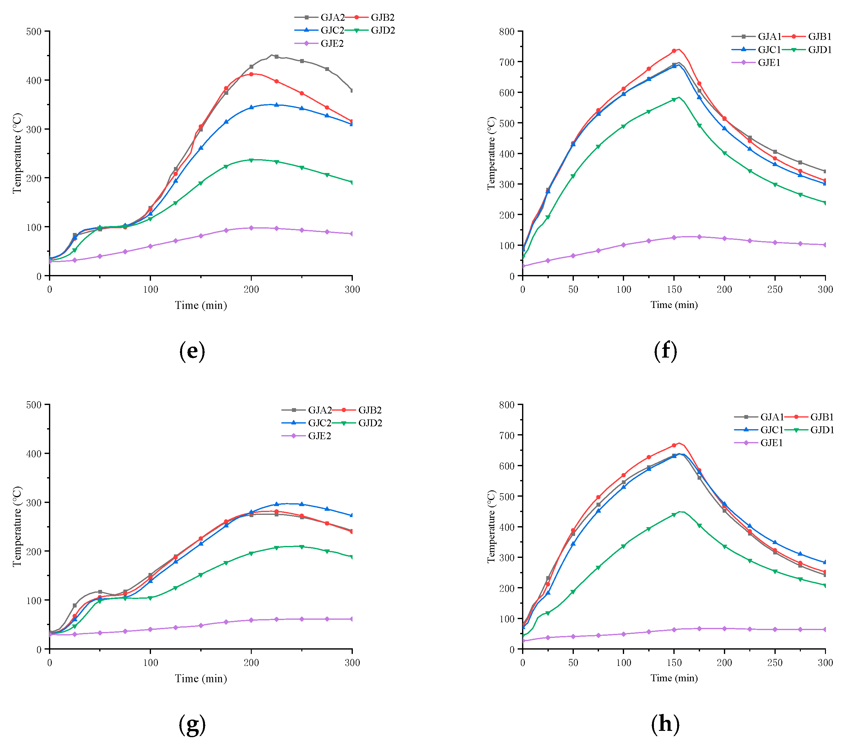
4.2. Temperature Field of Specimens

4.2.1. Temperature Field of Concrete

The temperature field distribution of the concrete in some control sections at the time of the fire is shown in Figure 13. Due to the burst of concrete at the bottom of the slab, information on the damage to individual measuring points was not obtained. The distribution pattern of the concrete temperature field of each specimen was basically the same: during 0~25 min at the beginning of the experiment, the temperature at measurement points 1 and 2 increased rapidly, reflecting when the fire occurred.
In observing the measurement points 3~5 in each figure, it was noted that when the temperature reached 100 °C, a brief temperature plateau occurred, caused by the evaporation of moisture reaching its boiling point, thus dissipating the heat and resulting in a temperature plateau on the curve. Furthermore, it was observed from the curve that the farther away from the fire surface, the longer the temperature plateau appeared; measuring points 1 and 2 had almost no temperature plateau. Near the midspan support of the nonfire span of the slab that was subjected to fire in the single-span experiment, the temperature increased due to the heat transferred by the fire span, albeit at a slower rate. This increase in temperature aligned with the trend of the change in the temperature of the fire span. After the bottom of the slab produced bursts, the temperature of the subsequently cast composite layer concrete significantly rose, with that at the top of the slab exceeding the specified fire-resistant limit.

4.2.2. Temperature Field of Steel Reinforcement

The temperature of the steel reinforcement at the time of the fire is shown in Figure 14. The thermal conductivity of steel reinforcements is higher than that of concrete, so the temperature of the longitudinal reinforcement at the upper part of the truss was higher than that of the concrete at the same level when the furnace heated up. In addition, the temperature of the concrete around this region was higher than that of the concrete at other positions at the same height, which led to greater thermal expansion at this location. The steel truss bore most of the shear force generated by the prefabricated layer and the stacked layer at the stacked surface due to the temperature gradient, which is the antibolting effect, which resulted in cracks along the direction of the tension stress concentration in the concrete at the location of the steel truss after the truss was placed. The tensile stress of the concrete at the location of the steel truss was concentrated, so cracks along the longitudinal reinforcement direction of the truss appeared on the slab surface. The thinner the stacked layer, the more likely cracks were to be produced. Due to the uneven thickness of the specimen caused by the bursting of the fire surface and cracks on the slab surface, the longitudinal bars at the top of the joist were at the same height, but there were differences in the temperature field. Since the top longitudinal bar was farther away from the concrete fire surface and the moisture in the nearby concrete was slow to absorb heat and evaporate, a temperature plateau effect occurred, and the curves showed a short-lived stagnation of warming when the temperature was approximately 100 °C, while the bottom longitudinal bar did not exhibit this phenomenon.
Referring to Figure 14c, the temperature at measurement point GJA1 on slab B2 rapidly increased at around 50 min due to the spalling of the bottom slab and direct exposure of the steel reinforcement to the fire. Additionally, this measurement point was located very close to the oil nozzle, resulting in significantly higher temperatures compared to the other measurement points at the same horizontal level. Measurement points GJD1 and GJE1, located near the midspan supports, exhibited lower temperatures as the bottom slab was less damaged in those areas.

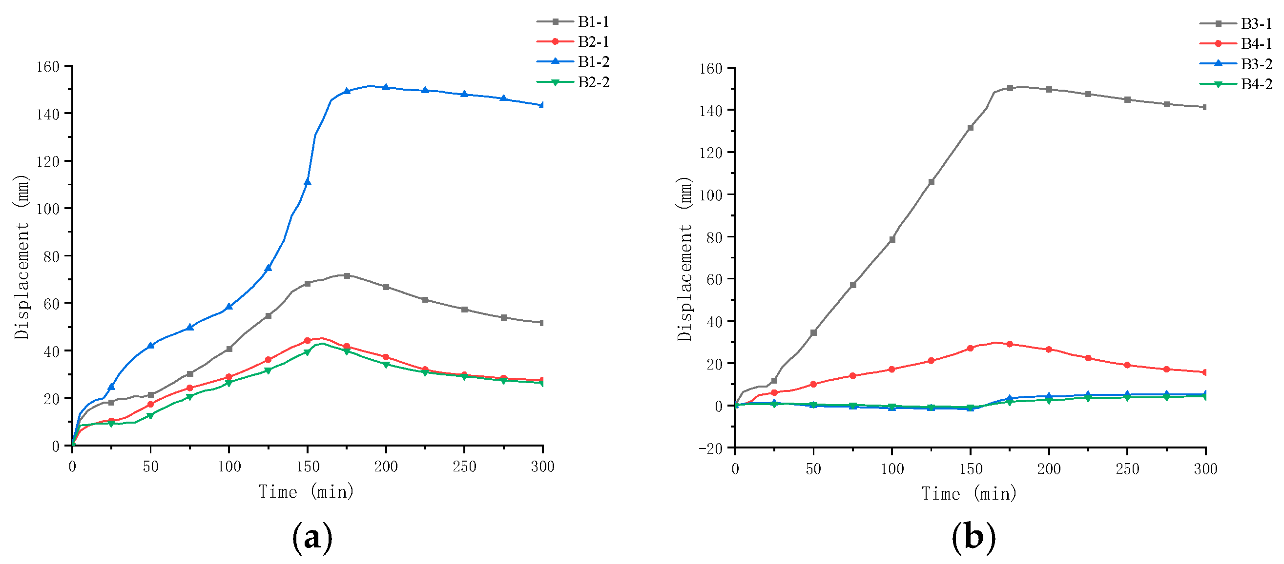
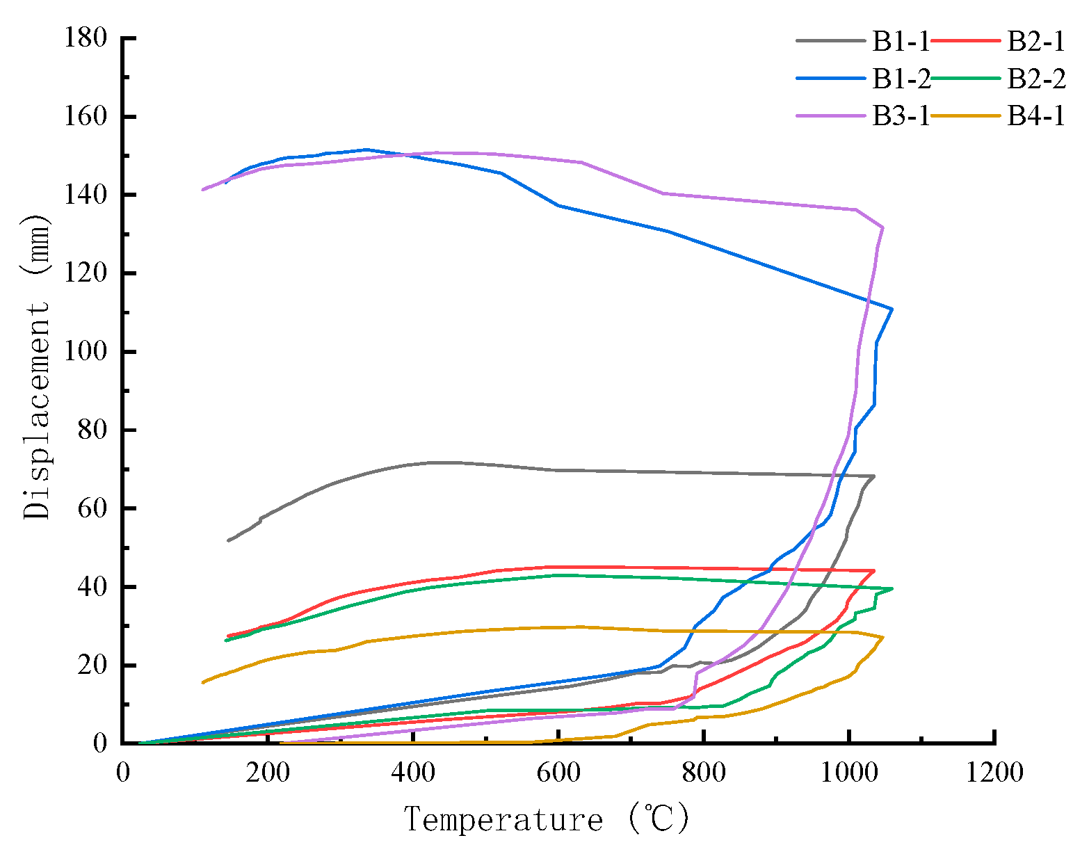
4.3. Deformation of the Specimen

The deflection–time curves for each span of the specimen are shown in Figure 15.
According to Figure 15, as the burning time increased, the temperature of the specimen gradually rose, and the deflection of the burning span of the specimen increased continuously. This was due to the degradation of the mechanical properties of both the concrete and reinforcement after exposure to high temperatures, resulting in a reduction in the specimen’s stiffness. Additionally, the spalling of the bottom concrete of the slab significantly reduced the stiffness of the specimen, leading to the deflection deformation of the structure. From Figure 15, it can be observed that the deflection of the fire-exposed span developed rapidly both in the early and later stages, with a horizontal segment in between. The reasons for this were as follows: in the early stage of the experiment, spalling of the bottom concrete occurred; in the later stage, the material properties degraded significantly, causing substantial damage to the specimen’s stiffness. Hence, deflection deformation occurred rapidly. When the moisture within the concrete was subjected to fire, the temperature of the concrete remained constant for a certain period, and the material properties did not change, resulting in the stiffness and deflection of the specimen remaining unchanged. Consequently, a horizontal segment appeared in the deflection–time curve.
Furthermore, from Figure 15, it is evident that the displacements of the measurement points continued to increase even after fire suppression. This could be attributed to the lag phenomenon between the furnace temperature and concrete temperature. Additionally, for the same specimen, the deflection deformations could vary significantly among different spans when subjected to fire due to differences in the extent of the spalling of the bottom concrete. The slab with a thickness of 60 mm for the postcast layer exhibited more significant deformation after the fire compared to the slab with a thickness of 80 mm, indicating that a smaller postcast layer thickness resulted in more severe stiffness damage during the fire incident. In the case of single-span fire exposure, the adjacent spans that were not subjected to fire experienced limited upward arching deformation.

4.4. Deformation of Specimen Midspan Deflection as a Function of Furnace Temperature

The relationship between the midspan deflection of the specimens and the furnace temperature is shown in Figure 16. The analysis revealed that when the furnace temperature was below 700 °C, the rate of displacement change was relatively small and followed a linear trend. Additionally, the specimens with a thickness of 100 mm exhibited a higher rate of displacement change in both fire experiments. Once the furnace temperature reached 700 °C, corresponding to approximately 200 °C for prestressing tendons and around 100 °C for the compressed zone of concrete, the degradation of both steel reinforcement and concrete materials occurred, resulting in a decrease in the overall specimen stiffness and an increase in the rate of deflection deformation. After reaching the peak temperature, and as the furnace temperature decreased, the specimens gradually recovered from their deformations. However, the recovery accounted for a relatively small proportion of the total deformation.

4.5. Fire Resistance Limit

The criteria for determining the fire resistance limit primarily include the load-bearing capacity, integrity, and thermal insulation performance of the specimens. From the experimental results, it was observed that the main failure modes of the multispan STPC slab after fire exposure was the delamination of the precast layer from the postcast overlay layer, with severe spalling of the prefabricated layer. However, due to the presence of the steel truss, the nonspalled sections of the combined precast and postcast layers still maintained certain overall performance, and the steel truss also contributed to the load-bearing capacity. The maximum deflection and bending deformation rate of the slab in the experiment did not exceed the specified limits. No temperature breakthrough was observed on the non-fire-exposed face of the specimens. Nevertheless, due to the spalling and detachment of the prefabricated layer at the bottom of the slab, the effective thickness of the slab reduced, resulting in an accelerated temperature rise on the upper surface, leading to decreased thermal insulation performance and a reduced fire resistance limit. According to the thermal insulation performance criteria, the fire resistance limits of specimens B1, B2, B3, and B4 were determined to be 90 min, 130 min, 91 min, and 135 min, respectively. It can be concluded that for a given thickness of a prefabricated bottom slab, increasing the thickness of the postcast layer results in a higher fire resistance limit.

5. Conclusions

This study experimentally investigated the fire resistance of multispan STPC slabs under the coupled action of high temperature and load using four specimens with a post-cast concrete layer with different thicknesses as well as different spans exposed to fire, through which the main conclusions obtained were as follows:
(1)
After being exposed to fire, the bottom of the multispan STPC slabs showed severe spalling, resulting in the significant detachment of the precast layer. This spalling was more pronounced than in the non-pre-stressed composite slabs and single-span prestressed steel truss composite slabs.
(2)
Under the coupled influence of temperature and load, the multispan prestressed steel truss composite slabs experienced horizontal cracks at the interface due to bond failure, yet the STPC slabs maintained satisfactory structural performance, which could be attributed to the presence of the steel bar truss.
(3)
Under the coupled influence of temperature and load, cracks occurred at the support point of the multispan prestressed steel truss composite slabs, where the negative reinforcement was cut. Considering fire resistance requirements, the anchorage length of the negative reinforcement at the slab support was appropriately extended.
(4)
The damage of the STPC slab specimens after fire was found to be more serious for those that had a thinner postcast concrete layer. In the single-span fire experiments, the structural performance of the unfired span was not prominently affected.
(5)
Due to the bursting and spalling of the precast layer, the thickness of the STPC slabs was reduced, resulting in decreases in the thermal insulation and the fire resistance limit. The fire resistance limits of the STPC slabs with 60 mm and 80 mm postcast concrete layers were 90 min and 130 min, respectively. When a high fire resistance limit of the STPC slab is required in design, it is recommended that the thickness of the postcast concrete layer be no less than 60 mm.

6. Future Work

In real applications of the multispan STPC slabs, their design parameters, including the span layout, boundary conditions, thickness of the postcast concrete layer, etc., may vary, resulting in different levels of fire resistance of the slabs. Further research is needed to investigate the influences of the above on the fire resistance of the STPC slabs through experimental and/or numerical analysis.

Author Contributions

Writing—original draft, K.Z. and S.L.; Writing—review & editing, J.L. and Z.F. All authors have read and agreed to the published version of the manuscript.

Funding

This research received no external funding.

Data Availability Statement

Data are contained within the article.

Conflicts of Interest

The authors declare no conflict of interest.

References

  1. Cheng, J.Y.; Zhao, L.; Yang, J.J. Study on short-term rigidity of precast composite slab with steel truss and concrete. Adv. Mater. Res. 2013, 639–640, 198–205. [Google Scholar] [CrossRef]
  2. Favarato, L.F.; Gomes, A.V.S.; Candido, D.C.d.M.; Ferrareto, J.A.; Vianna, J.d.C.; Calenzani, A.F.G. On the composite behavior of a rebar truss ribbed slab with incorporated shuttering made of lipped channel section. J. Build. Eng. 2022, 55, 104663. [Google Scholar] [CrossRef]
  3. Wang, Q.; Ranzi, G.; Wang, Y.; Geng, Y. Long-term behaviour of simply-supported steel-bars truss slabs with recycled coarse aggregate. Constr. Build. Mater. 2016, 116, 335–346. [Google Scholar] [CrossRef]
  4. Li, W.J. Experimental Study and Analysis on Flexural Performance of Prestressed Concrete Composite Slabs. Ph.D. Thesis, Chongqing University, Chongqing, China, 2018. (In Chinese). [Google Scholar]
  5. Li, Y.X.; Jiang, L.; Yu, Z.Q.; Li, J.; Li, Y.W. Experiment research on the behaviors of steel bar truss and concrete superimposed floor slabs. In Applied Mechanics and Materials; Trans Tech Publications Ltd.: Xi’an, China, 2012; Volume 166, pp. 3–8. [Google Scholar]
  6. Zhao, L. Research on the Design and Calculation Method of Self-Anchored Steel Truss Reinforced Concrete Composite Slabs. Ph.D. Thesis, Central South University, Changsha, China, 2007. (In Chinese). [Google Scholar]
  7. Zhang, W.R. Research on the Design Method of Self-Anchored Steel Truss Prestressed Concrete Composite Slabs. Ph.D. Thesis, Shandong Jianzhu University, Jinan, China, 2015. (In Chinese). [Google Scholar]
  8. Ma, X.L. Research on the Mechanical Performance of Truss Reinforced Concrete Composite Slabs. Ph.D. Thesis, Southeast University, Nanjing, China, 2018. (In Chinese). [Google Scholar]
  9. Guo, S.; Bailey, C.G. Experimental behaviour of composite slabs during the heating and cooling fire stages. Eng. Struct. 2011, 33, 563–571. [Google Scholar] [CrossRef]
  10. Deng, L.B.; Wu, F.B.; Zhou, X.H.; Liu, B.; Li, J. Experimental study on fire resistance performance of prestressed concrete simply supported composite slabs. J. Build. Struct. 2015, 45, 65–70. (In Chinese) [Google Scholar]
  11. Deng, L.B.; Wu, F.B.; Zhou, X.H.; Liu, B.; Li, J. Parametric analysis of fire resistance performance for prestressed precast composite floor. Fire Sci. 2015, 24, 32–39. (In Chinese) [Google Scholar]
  12. Wang, Y.; Wang, G.; Huang, Z.; Li, L.; Bu, Y.; Zhong, B.; Zhang, Y.; Ma, S. Numerical modelling of in-plane restrained concrete two-way slabs subjected to fire. Fire Saf. J. 2021, 121, 103307. [Google Scholar] [CrossRef]
  13. Zhang, T. Experimental Study on Fire Resistance Performance of One-Way Simply Supported Composite Slabs. Ph.D. Thesis, Shandong Jianzhu University, Jinan, China, 2018. (In Chinese). [Google Scholar]
  14. Zhao, K.Z.; Wei, X.; Ren, X. Experimental study on fire resistance performance of four-side simply supported steel truss reinforced concrete composite slabs. Eng. Mech. 2022, 40, 1–9. (In Chinese) [Google Scholar]
  15. Wang, Y.; Bisby, L.A.; Wang, T.; Yuan, G.; Baharudin, E. Fire behaviour of reinforced concrete slabs under combined biaxial in-plane and out-of-plane loads. Fire Saf. J. 2018, 96, 27–45. [Google Scholar] [CrossRef]
  16. Zhao, K.Z.; Wei, F.X.; Gao, W. Experimental study on fire resistance performance of prestressed composite slabs. J. Build. Struct. 2022, 43, 140–148. (In Chinese) [Google Scholar]
  17. Xu, Q.; Chen, L.; Li, X.; Han, C.; Wang, Y.C.; Zhang, Y. Comparative experimental study of fire resistance of two-way restrained and unrestrained precast concrete composite slabs. Fire Saf. J. 2020, 118, 103225. [Google Scholar] [CrossRef]
  18. Omer, E.; Izzuddin, B.A.; Elghazouli, A.Y. Failure of unrestrained lightly reinforced concrete slabs under fire, Part I: Analytical models. Eng. Struct. 2010, 32, 2631–2646. [Google Scholar] [CrossRef]
  19. Omer, E.; Izzuddin, B.A.; Elghazouli, A.Y. Failure of unrestrained lightly reinforced concrete slabs under fire, Part II: Verification and application. Eng. Struct. 2010, 32, 2647–2657. [Google Scholar] [CrossRef]
  20. Wang, Y.; Wang, G.; Huang, Z.; Huang, Y.; Wang, B.; Gu, A.; Zhang, C.; Jiang, Y.; Zhang, X. Experimental studies and theoretical analysis of the residual properties of three-span small-scale continuous concrete slabs after a fire. Fire Saf. J. 2021, 126, 103481. [Google Scholar] [CrossRef]
  21. Wang, Y.; Chen, Z.; Jiang, Y.; Huang, Z.; Zhang, Y.; Huang, Y.; Li, L.; Wu, J.; Guo, W. Residual properties of three-span continuous reinforced concrete slabs subjected to different compartment fires. Eng. Struct. 2020, 208, 110352. [Google Scholar] [CrossRef]
  22. Wang, Y.; Jiang, Y.; Huang, Z.; Li, L.; Huang, Y.; Zhang, Y.; Zhang, G.; Zhang, X.; Duan, Y. Post-fire behaviour of continuous reinforced concrete slabs under different fire conditions. Eng. Struct. 2021, 226, 111342. [Google Scholar] [CrossRef]
  23. Wang, Y.; Duan, Y.; Ma, S.; Huang, Z.; Zhang, Y.; Wu, J.; Yuan, G.; Zhou, M.; Zhang, G. Behaviour of continuous reinforced concrete floor slabs subjected to different compartment fires. Eng. Struct. 2019, 197, 109445. [Google Scholar] [CrossRef]
  24. Wang, Y.; Wu, J.; Huang, Z.; Jiang, J.; Yuan, G.; Zhang, Y.; Jiang, Y.; Chen, Z.; Zhou, M. Experimental studies on continuous reinforced concrete slabs under single and multi-compartment fires with cooling phase. Fire Saf. J. 2020, 111, 102915. [Google Scholar] [CrossRef]
  25. Ma, S. Research on the Mechanical Performance of Concrete Continuous Slabs under the Spreading Effect of Fire. Ph.D. Thesis, China University of Mining and Technology, Xuzhou, China, 2020. (In Chinese). [Google Scholar]
  26. Wu, J.C. Experimental Study on Mechanical Performance of Post-Fire Concrete Continuous Bidirectional Slabs. Ph.D. Thesis, China University of Mining and Technology, Xuzhou, China, 2020. (In Chinese). [Google Scholar]
  27. ISO834; Fire Resistance of Building Components Test Method Part 1: General Requirements. China Architecture & Building Press: Beijing, China, 2008. (In Chinese)
  28. Yang, Z.; Dong, Y. Experimental study of two way reinforced concrete slab subjected to fire in a steel framed building. Eng. Mech. 2013, 30, 337–344. (In Chinese) [Google Scholar]
  29. Zhu, C.; Dong, Y. An energy method for calculation the load-carrying capacity of two-way slabs with two edges simply supported and two edges clamped in fire. Eng. Mech. 2018, 35, 67–99. (In Chinese) [Google Scholar]
  30. Yang, Z.; Dong, Y.; Lv, J.; Li, S.; Peng, P. Experimental study of two-way reinforced concrete slab subjected to fire in a whole structure. J. Build. Struct. 2012, 33, 96–103. (In Chinese) [Google Scholar]
Figure 1. Precast prestressed concrete slab.
Buildings 14 00080 g001
Figure 2. Precast slab construction: (a) reinforcement detailing for precast concrete bottom slab; (b) section of steel truss; (c) 1-1 cross-section.
Buildings 14 00080 g002
Figure 3. Arrangement of control sections of specimen temperature and displacement measurement points. (a) Locations of temperature measurement points; (b) locations of displacement measurement points.
Buildings 14 00080 g003
Figure 4. Arrangement diagram of temperature measurement points for control section A along the height direction of the cross-section.
Buildings 14 00080 g004
Figure 5. Layout diagram of specimens in the furnace. (a) Plan layout diagram of specimens in the furnace; (b) elevation layout diagram of specimens in the furnace.
Buildings 14 00080 g005
Figure 6. Slabs applying uniform load.
Buildings 14 00080 g006
Figure 7. Experiment phenomena of specimens B1 and B2 in fire. (a) Lateral cracks on the surface of the slab; (b) water vapor on the surface of the slab; (c) delamination between the precast layer and the postcast layer; (d) fracture of the postcast layer.
Buildings 14 00080 g007
Figure 8. Experiment phenomena of specimens B3 and B4 in fire. (a) Lateral cracks on the surface of the slab; (b) fracture of the postcast layer at the location of the cut-off of the negative reinforcement in the fire span of specimen B4.
Buildings 14 00080 g008
Figure 9. Damage pattern on the bottom surface of the slab after the fire exposure. (a) Bottom surface of specimen B1-2; (b) bottom surface of specimen B2-1; (c) bottom surface of specimen B3-1; (d) bottom surface of specimen B4-1.
Buildings 14 00080 g009
Figure 10. Damage pattern on the side of specimen B1-2 after the fire experiment.
Buildings 14 00080 g010
Figure 11. Damage pattern on the upper part of the specimens after the fire experiment. (a) Lateral cracks on the upper part of spans B1-1 and B2-1 of the slab; (b) vertical cracks on the upper part of spans B1-2 and B2-2 of the slab; (c) cracks at the midsupport locations of specimens B1 and B2; (d) crack distribution on the burning spans and support surfaces of specimens B3 and B4.
Buildings 14 00080 g011
Figure 12. Comparison between the measured furnace temperature curve and the ISO-834 standard curve [27].
Buildings 14 00080 g012
Figure 13. Temperature–time curves of the concrete temperature measurement points in the specimens. (a) Specimen B1-1, cross-section B; (b) specimen B1-2, cross-section G; (c) specimen B2-1, cross-section B; (d) specimen B3, fire-affected cross-section B; (e) specimen B4, fire-affected cross-section B; (f) specimen B3, fire-affected cross-section D; (g) specimen B3, non-fire-affected cross-section E.
Buildings 14 00080 g013
Figure 14. Temperature–time curves of the steel reinforcement temperature measurement points in the specimens. (a) Upper chord reinforcement of the truss for specimen B1; (b) lower chord reinforcement of the truss for specimen B1; (c) upper chord reinforcement of the truss for specimen B2; (d) lower chord reinforcement of the truss for specimen B2; (e) upper chord reinforcement of the truss for specimen B3; (f) lower chord reinforcement of the truss for specimen B3; (g) upper chord reinforcement of the truss for specimen B4; (h) lower chord reinforcement of the truss for specimen B4.
Buildings 14 00080 g014aBuildings 14 00080 g014b
Figure 15. Displacement–time curves for each span of the specimens. (a) Deflection–time curves of spans B1 and B2; (b) deflection–time curves of spans B3 and B4.
Buildings 14 00080 g015
Figure 16. Deflection–temperature curves at the middle of the span.
Buildings 14 00080 g016
Table 1. The criterion for judging the load-bearing capacity of the specimens.
SpecimenTermination Time of the Experiment (s)Maximum Deflection (mm)Prescribed Deflection Limit (mm)Maximum Bending Deformation Rate (mm/min)Prescribed Limit of Bending Deformation Rate (mm/min)
B1-115071.62872.112.8
B1-2150169.32874.712.8
B2-115072.72392.510.6
B2-215046.42391.710.6
B3-1153153.82871.612.8
B4-115344.32390.7910.6
Table 2. The insulation performance evaluation of the experimental specimen.
SpecimenTime with an Average Temperature Difference Greater Than 140 °C (min)Temperature Difference at a Specific Point Exceeds 180 °C
Time Point (min)Measurement Point
B113090G5
B2>150130H5
B39591B5
B4>150135B5
Disclaimer/Publisher’s Note: The statements, opinions and data contained in all publications are solely those of the individual author(s) and contributor(s) and not of MDPI and/or the editor(s). MDPI and/or the editor(s) disclaim responsibility for any injury to people or property resulting from any ideas, methods, instructions or products referred to in the content.

