Abstract
This research focuses on the thermal properties of three distinctive paraffin waxes—PCMA, PCMB, and PCMC—each characterized by a specific melting point. The crucial phase transition temperature intervals and latent heat values were examined using differential scanning calorimetry (DSC) in the temperature range of 0 °C to 80 °C. These parameters are pivotal for the effective application of these phase change materials (PCMs) in building envelopes, influencing the overall heat storage performance. The study delved into the development and encapsulation of blends containing both the phase change material (PCM) and graphite. This involves combining the chosen PCM with graphite powder and examining the weight ratios of 10% and 20%. The thermal characteristics of these blends revealed that a 10% ratio of graphite powder proved effective in improving the PCM with graphite. This resulted in a reduced range of melting and solidification temperatures while maintaining the essential chemical structure of the PCM without additives. Furthermore, the practical application of PCM–graphite composites within a building’s envelope was explored, revealing a substantial reduction in heat transfer from the exterior to the interior of the building. This underscores the potential for energy-efficient building designs.
1. Introduction
Presently, the urgent concern of global warming has attained a critical magnitude, with its effects reverberating worldwide [1,2,3,4]. The emission of greenhouse gases (GHGs), notably carbon dioxide (CO2), plays a pivotal role in driving the alarming escalation of global temperatures [5]. Of notable concern is the substantial contribution of commercial and residential structures to the ever-increasing utilization of fossil fuels [6]. Buildings, in fact, shoulder a considerable responsibility, accounting for a substantial 40% of the planet’s total energy consumption and concurrent CO2 emissions [7]. Within the ambit of this energy consumption, a significant portion is allocated to heating and cooling systems, a necessity for achieving the desired indoor thermal comfort [8]. Particularly in tropical regions, where relentless heat and year-round, intense solar radiation foster heat accumulation within structures, the majority of energy consumption in these locations is directed toward maintaining indoor comfort, primarily through air conditioning systems [9]. To address this challenge, passive cooling techniques have gained prominence as a compelling alternative to traditional cooling systems [10]. Among these innovative strategies, latent heat energy storage stands out as a highly effective means of enhancing the thermal inertia of building envelopes, thus decreasing temperature fluctuations and ultimately elevating the quality of the indoor living conditions for occupants [11]. Phase change materials (PCMs), designed for latent heat energy storage, are particularly promising in this regard [12]. PCMs encompass a diverse range of organic and inorganic compounds that exhibit the remarkable ability to undergo phase transitions within temperature ranges customized for specific applications [13]. This intrinsic quality enables PCMs to absorb and release substantial quantities of heat during these phase transitions [14,15]. In recent times, PCMs have found extensive application in various facets of building envelopes including walls [16,17], windows [18,19], ceilings [20,21,22], and roofs [23,24,25]. These applications not only contribute to significant reductions in energy consumption, but also result in an appreciable enhancement of the thermal comfort experienced within these buildings.
Paraffin stands out as one of the most widely adopted organic PCMs due to its reputation for safety, reliability, cost-effectiveness, and its impressive latent heat capacity, all of which are essential attributes for applications within building environments [26]. Nevertheless, the utility of paraffin as a PCM is constrained by its relatively low thermal conductivity, which limits its versatility in practical applications [27]. The identification of methods to improve the heat transfer efficiency of paraffin-based PCMs has sparked various approaches, as indicated in the current body of literature [28,29]. For instance, P. Yan et al. employed a nature-inspired strategy by incorporating Y-shaped fins to augment the heat transfer characteristics of paraffin. Their numerical simulations revealed that the incorporation of these nature-inspired solid fins significantly reduced the melting time, demonstrating potential applications in thermal energy storage and management [28]. In a different way, H. Zheng et al. investigated the use of copper foam to enhance the thermal efficiency of paraffin-based PCMs. Employing a blend of experimental and numerical analyses, they illustrated a significant 20.5% decrease in the melting time of the composite PCM incorporating copper foam in contrast to pure paraffin. Their study thoughtfully examined the influence of the heating position on this improvement [29]. M. Iasiello et al. conducted experiments and numerical investigations into the use of PCM–aluminum foam combinations under various conditions, focusing on the augmentation of overall thermal conductivity. Their findings revealed that reduced porosity considerably shortened the PCM melting time, while the number of pores per inch (PPIs) and orientation exhibited minimal effects [30]. Meanwhile, C. Zhao et al. explored the integration of graphite foam inserts to expedite the melting and solidification processes of high-temperature PCMs within a thermal storage tank. Their results were indicative of a significant reduction in process duration, with a 0.9 porosity foam condition achieving notably faster melting and solidification times compared to instances where no insert graphite foam was used [31]. In another study, M. Bashar et al. ventured into the incorporation of various nanoparticles into paraffin wax, transforming it into a nanoparticle–PCM mixture within a rectangular enclosure. Their investigation revolved around understanding the transient melting and heat transfer dynamics of these mixtures. Silver and copper oxide nanoparticles emerged as high performers, outstripping aluminum oxide and carbon nanotubes in terms of enhancing heat transfer. Notably, a 6% mass fraction of copper oxide nanoparticles exhibited the most favorable thermal performance, achieving a 25% higher melting rate in comparison to the plain PCM [32].
The thermal energy storage (TES) efficiency of paraffin was enhanced by integrating three distinct paraffin variants with different melting temperature ranges using a high thermal conductivity material, graphite powder (GP). The focus of this investigation was on evaluating the thermal characteristics of both the PCM without integrated graphite and the PCM–graphite powder (GP) composites. The differential scanning calorimetry (DSC) technique was employed to comprehensively analyze their thermal properties. Furthermore, the study extends to assess the thermal performance of these materials when implemented in the building envelope, with a specific emphasis on the ceiling and roof. These regions are of paramount importance as they constitute the uppermost part of a building and are subjected to direct sunlight exposure, which contributes to nearly 50% of the total heat influx into the structure [33]. The results of this analysis bear direct relevance to thermal energy storage (TES) efficiency and the practical suitability of these materials for integration within building envelopes. The overarching objective is to curtail heat transfer from the external environment to the interior of the building, thereby facilitating energy conservation within the structure.
2. Materials and Methods
2.1. Thermal Behavior Analysis of PCM without Infused Graphite Powder
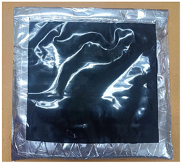
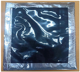
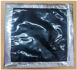
In the context of this study, an exploration was conducted on three distinct paraffin waxes, each characterized by unique melting points. At typical room temperatures ranging from approximately 27–33 °C, PCMA stood out as the least hard among the three PCMs. It is characterized by an opaque white appearance and has an approximate density of 1536.15 kg/m3. In contrast, PCMB exhibited a slightly softer texture, appearing white with moderate opacity and having a density of approximately 1389.70 kg/m3. Meanwhile, PCMC, in its solid state, showcased the highest level of hardness among all PCMs. It maintained a colorless composition and possessed a density measuring around 1143.88 kg/m3, as illustrated in Figure 1. The thermal properties of these PCM variants were thoroughly analyzed using the differential scanning calorimetry (DSC) technique. This assessment encompassed a temperature range spanning from 0 °C to 80 °C, employing a controlled heat rate of 5 °C per minute. The phase transition temperature intervals and the latent heat associated with the melting and solidification processes of these PCMs hold pivotal importance for their application within building envelopes as these factors significantly influence the overall heat storage performance [34,35].

Figure 1.
Three distinct paraffin waxes, each distinguished by its specific melting point: (a) PCMA; (b) PCMB; and (c) PCMC.
2.2. Preparation and Encapsulation of PCM–Graphite Composites
In this section, a PCM was characterized by high latent heat values and ideal melting and solidification temperature ranges suitable for building envelope applications. Subsequently, this PCM was liquidized and mixed with graphite powder at different weight ratios of 10% and 20%, respectively. To ensure uniform dispersion of the graphite powder and prevent any irregular distribution, the solutions were continuously agitated until solidification occurred, resulting in the formation of composites, as illustrated in Figure 2. The weight percentages of graphite powder (GP) within the PCM/GP composites were calculated using Equation (1).

Figure 2.
The schematic of the preparation of the PCM/graphite composites.
The thermal behavior of these PCM–GP composites was investigated through DSC, similar to the PCMs without infused graphite powder examined in Section 2.1. Both the PCM with no integrated graphite and the PCM–GP composites were uniformly molded into dimensions of 20 cm × 20 cm × 1 cm and enclosed in polyethylene (PE) bags. Each unit was carefully sealed along the edges with aluminum tape to prevent any PCM leakage. Subsequently, they were arranged within a metal wire mesh to create layers of PCM without infused GP and PCM–GP, each measuring 100 cm × 100 cm, as illustrated in Figure 3. The price of the PCM without infused graphite layer and the PCM–GP layer was around 3.88 USD/m2 and 6.16 USD/m2. These layers were subsequently integrated above the ceiling and below the roof of the building model to test their thermal performance.
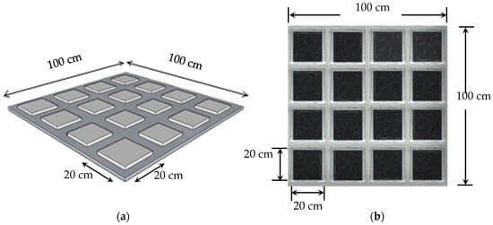
Figure 3.
The PCM layout. (a) Dimensions of the PCM layer utilized in the experiments; (b) samples of the PCM–GP layers prepared for integration into the building envelope.
2.3. Utilizing PCM–Graphite Composites in Building Envelopes
In the assessment of the practical application of PCM layers without infused graphite powder (PCM layers) and PCM–graphite composite layers (PCM–GP layers) within a building’s envelope, specifically its ceiling and roof, the effectiveness in mitigating heat transfer from the external environment to the interior of the structure was evaluated. To emulate a cubic room with dimensions of 100 cm × 100 cm × 100 cm, the building model was constructed using 0.05 cm thick plywood sheets. The interior walls were insulated with polyethylene sheets. The ceiling of the model, with dimensions of 100 cm × 100 cm and a thickness of 1 cm, was composed of gypsum board, replicating the typical composition of practical building ceilings. For the roof of the testing model, corrugated steel sheets, 0.025 cm in thickness, were employed. Additionally, the attic was fabricated from plywood sheets and positioned at an angle of approximately 40° from the horizontal, as shown in Figure 4, Figure 5 and Figure 6. In tropical regions, various factors including architectural design, climatic conditions, and construction methodologies contribute to specific considerations. In areas with abundant rainfall, there is a tendency to adopt steeper roof inclinations to ensure efficient water drainage. Additionally, to meet the recommended minimum pitch requirement of 12° [36] for the chosen roofing material, our roof was estimated to have an inclination angle of around 40°.
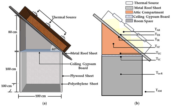
Figure 4.
Testing model. (a) Model schematic for testing; (b) locations of the stationary thermocouples for temperature measurement in the absence of PCM layers.

Figure 5.
Testing model. (a) Model schematic for testing; (b) placement of stationary thermocouples for measuring temperatures with PCM layers on the ceiling.
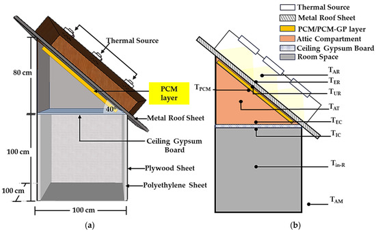
Figure 6.
Testing model. (a) Schematic diagram of the model for testing and (b) positions of the fixed thermocouples for measuring temperatures with PCM layers under the roof condition.
Within the framework of this building model, three distinct layers—the PCM layer (with no infused graphite), the PCM-10%GP layer, and the PCM-20%GP layer—were integrated, strategically positioned beneath the roof and on the ceiling board. These configurations were subjected to controlled temperature experiments, facilitated by a basic voltage control system. The regulation of the exterior metal roof surface temperature (referred to as TER) involved the utilization of a thermal source consisting of nine halogen lamps, each rated at 500 watts. These lamps were situated at a distance of 30 cm from the outer roof surface and operated to attain different temperature levels, specifically 45 °C, 55 °C, and 65 °C, maintaining each temperature level for a duration of 300 min. Simultaneously, an extensive temperature monitoring process was conducted at various critical points, encompassing the region above the metal roofing sheet (TAR), the external surface (TER), and the internal surface (TIR) of the metal roofing sheet. Monitoring also extended to the enclosed space within the attic compartment (TAT), the temperature of the PCM or PCM–GP layers (TPCM), the exterior ceiling surface temperature (TEC), the interior ceiling surface temperature (TIC), the room interior temperature (Tin-R), and the ambient temperature in the immediate surroundings (TAM), as displayed in Figure 4, Figure 5 and Figure 6. Furthermore, to maintain consistent environmental conditions, an air conditioning system was employed to stabilize the ambient temperature (TAM) at approximately 27 °C. Temperature readings were collected at each of these designated locations at specified intervals of 5 min and continuously recorded over the course of 300 min with the aid of a data logger, ensuring comprehensive data acquisition and analysis.
3. Results and Discussion
3.1. Thermal Characteristics of PCMs without Infused Graphite Powder
The selection of PCMs for building envelopes, with the aim of reducing cooling demands, depends significantly on the range of phase transition temperatures, as previously documented [37]. To optimize their effectiveness, PCMs should possess a substantial latent heat capacity and exhibit a melting point that is slightly below the temperature of the building envelope [36]. In this study, a comprehensive analysis of the thermal properties of paraffin as a PCM was conducted using DSC, spanning from 0 °C to 80 °C, as depicted in Figure 7. The DSC outcomes revealed distinctive endothermic and exothermic process curves for three paraffin types without infused graphite—PCMA, PCMB, and PCMC—each distinguished by varying melting points.
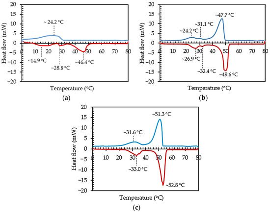
Figure 7.
DSC findings illustrating the thermal characteristics of PCMs: (a) PCMA; (b) PCMB; (c) PCMC.
In the analysis of PCMA using DSC, three distinct endothermic peaks were observed within the temperature range of 0 °C to 80 °C, as depicted in Figure 7a. The initial peak appeared at approximately 14.9 °C, involving a heat absorption of 30.56 J/g. A secondary, minor peak manifested at approximately 28.8 °C, indicating a heat absorption of 8.37 J/g. These peaks (TM) correspond to the initiation of the PCMA phase transition to a liquid state. The final endothermic peak was observed at around 46.4 °C, with a latent heat of fusion (ΔHML) measuring 66.61 J/g. This ultimate endothermic peak represents the transition of paraffin from a solid to a liquid state, marking the solid–liquid temperature transition (TML), as exhibited in Table 1. The comprehensive analysis provides insights into the thermal behavior of PCMA, crucial for understanding its applicability in thermal energy storage systems and related applications. As the temperature decreased from 80 °C to 0 °C, a solitary exothermic reaction peak emerged. This exothermic peak, associated with a solidification latent heat (ΔHSL) of 75.18 J/g, occurred at approximately 24.2 °C. It corresponded to the thermal release of paraffin during the solidification process, signifying a transition from a liquid to a solid state, referred to as the liquid–solid temperature (TSL), as illustrated in Table 1 and Figure 7a.

Table 1.
The temperatures and latent heat associated with the endothermic and exothermic peaks for PCMA, PCMB, and PCMC.
The thermal behavior of PCMB in the temperature range of 0 °C to 80 °C is depicted in Figure 7b, and the corresponding data are presented in Table 1. Within this range, three endothermic peaks were observed during the endothermic process. The initial endothermic peak was evident at approximately 26.9 °C, with an associated enthalpy of 17.14 J/g. The second endothermic peak manifested around 32.4 °C, characterized by an enthalpy of 1.60 J/g. Both of these peaks (TM) could be the beginning of PCMB transitioning from a solid into a liquid. The third endothermic peak, occurring at approximately 49.6 °C (TML), had a melting latent heat of 148.24 J/g (ΔHML), indicating the transition of PCMB from a solid to a liquid state. During the cooling phase, from 80 °C to 0 °C, the endothermic curve of PCMB revealed three exothermic reaction peaks. The DSC analysis for PCMB revealed three significant exothermic peaks, each offering insights into the thermal behavior of the paraffin material. The initial exothermic peak, occurring at approximately 47.7 °C (TSL), signified a solidification latent heat of 144.92 J/g (ΔHSL). A second, smaller exothermic peak manifested at around 31.1 °C (TS), accompanied by a heat release of 1.32 J/g. The final exothermic peak, noted at approximately 24.2 °C (TS), involved a heat release of 13.96 J/g. These peaks marked the thermal release of paraffin during the solidification process, transitioning from a liquid to a solid state. Understanding these thermal characteristics is crucial for optimizing the utilization of PCMB in thermal energy storage applications.
In the assessment of PCMC using DSC, the temperature ranges from 0 °C to 80 °C revealed two distinct endothermic peaks, as illustrated in Figure 7c and detailed in Table 1. The initial endothermic peak, identified at around 33.0 °C (TM), involved a heat absorption of 35.78 J/g. The second endothermic peak occurred at approximately 52.8 °C (TML), accompanied by a melting latent heat of 153.65 J/g (ΔHML), signifying the transition of PCMC from a solid to a liquid state. Conversely, during the temperature decrease from 80 °C to 0 °C, two exothermic peaks were observed, as depicted in Figure 7c and summarized in Table 1. These exothermic peaks denote the thermal release of heat from PCMC. This detailed analysis sheds light on the thermal characteristics of PCMC, providing valuable information for optimizing its application in thermal energy storage systems and related technologies. In the advanced exploration of PCMC through DSC, two notable exothermic peaks were identified, offering insights into the material’s thermal behavior. The initial exothermic peak, occurring at approximately 51.3 °C (TSL), was linked to a solidification latent heat of 151.96 J/g (ΔHSL). This peak signified the thermal release of heat as PCMC transitioned from a liquid to a solid state, indicating the solidification process. The second exothermic peak appeared around 31.6 °C (TS), with a heat release of 29.71 J/g. Understanding these thermal characteristics is vital for optimizing the application of PCMC in various contexts, especially in thermal energy storage systems where the precise control of phase transitions and heat release is essential for efficient energy management.
These results suggest that the temperature intervals for both the melting and solidification phases of PCMC are ideal for applications aimed at reducing indoor temperatures and minimizing heat transfer through roofs and ceilings. PCMC’s exceptional performance is attributed to its high latent heat values during phase transition, surpassing those of other PCMs. Furthermore, the transition temperature range of PCMC is strategically situated just below the typical temperatures experienced by roofs and ceilings in tropical regions, which commonly reach an average range of approximately 55 °C to 70 °C [38].
3.2. Thermal Analysis of the PCM–GP Composites
To explore the influence of different weight percentages of graphite powder on the phase change behavior of PCM–GP composites, paraffin-based PCMC was combined with graphite powder at two distinct ratios: 10% and 20% by weight. The DSC profiles of plain PCMC and the PCMC–GP composites, assessed within a temperature range spanning from 0 °C to 80 °C, are depicted in Figure 8 and detailed in Table 2. Upon introducing graphite powder, the DSC curves of the PCMC–GP composites exhibited shapes closely resembling those of PCMC without infused graphite, although with a minor adjustment in the melting and solidification points compared to PCMC. The original PCMC had a melting point at 52.8 °C. When 10% and 20% graphite powder were incorporated, the melting point temperature experienced a marginal increase, reaching 53.4 °C and 54.4 °C, respectively. In the solidification process of PCMC without graphite, the solidification point occurred at 51.3 °C. With the addition of 10% and 20% graphite powder by weight, there was a very slight decrease in the solidification point temperature, registering at 51.3 °C and 50.8 °C, respectively. Importantly, the curves of the PCMC–GP composites closely resembled those of paraffin wax without infused graphite (PCMC), indicating that the addition of graphite powder did not cause any chemical reactions or modify the chemical structure of the PCM [39].
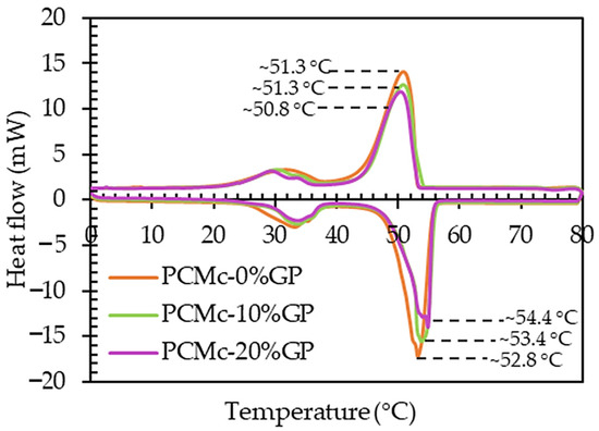
Figure 8.
DSC results showing the thermal behavior of the PCMC without the infused GP (0%GP), the PCMC-10%GP, and the PCMC-20%GP composites.

Table 2.
The width of the phase transition temperature ranges of the PCMC and PCMC–GP composites.
The width of the melting temperature range (TML) for the PCMC (0%GP), PCMC-10%GP, and PCMC-20%GP composites was approximately 6.4 °C, 4.1 °C, and 5.2 °C, respectively. In contrast, the width of the solidification temperature range (TSL) for these materials was approximately 8.6 °C, 8.5 °C, and 8.6 °C, as detailed in Table 2. Notably, the PCMC-10%GP composite demonstrated a narrower phase transition temperature range in comparison to both the PCMC (0%GP) and PCMC-20%GP composites. This reduced range signifies the effectiveness of incorporating graphite powder into the PCM, specifically emphasizing the optimal ratio for reducing the heat absorption and heat release time of the PCM [40]. Especially during the endothermic process, the PCMC-10%GP composite exhibited a 35.94% lower melting time in comparison to plain PCM. Moreover, 35.94% was higher than that of combining Y-shaped fins with a PCM system (34% reduction in time compared to a conventional PCM system to achieve complete melting) [28], copper foam/paraffin composite (the melting time was reduced by 20.5% compared to pure paraffin) [29], and the incorporation of copper oxide nanoparticles into paraffin wax (the melting rate was 25% higher compared to ordinary PCM) [32]. In this study, this enhancement is exemplified by the PCMC-10%GP composite, highlighting the potential for improved thermal performance while maintaining a well-defined phase transition temperature range.
As indicated in Table 3, the latent heat (ΔH) of the PCM–GP composites was observed to be lower than that of paraffin wax without infused GP (the PCMC). This variation can be attributed to the fact that graphite powder (GP) does not actively participate in the latent heat phenomenon [41]. Consequently, in theory, the ΔH of the PCM–GP composites should exhibit a direct proportionality to the paraffin wax content, a relationship that can be calculated using Equation (2) [41].
Here, ΔH(PCM-GP) represents the latent heat of the PCM–GP composites, ϕ denotes the percentage content of paraffin wax, and ΔH(PCM) stands for the latent heat of the phase transition of paraffin wax without infused graphite (PCM).
ΔH(PCM-GP) = ϕΔH(PCM),

Table 3.
The latent heat from the DSC results and theoretical of the PCMC and PCMC–GP composites.
Regarding the endothermic process, the melting latent heat (ΔHML), as determined by DSC, was approximately 153.65 J/g for PCMC (0%GP), 133.58 J/g for the PCMC-10%GP composite, and 117.48 J/g for the PCMC-20%GP composite. Simultaneously, the calculated melting latent heat (ΔHML.cal), calculated using Equation (2), for the PCMC-10%GP and PCMC-20%GP composites was approximately 138.29 J/g and 122.92 J/g, respectively, as illustrated in Table 3. Notably, the DSC-measured values for ΔH in the PCMC-10%GP and PCMC-20%GP composites were observed to be slightly lower than the corresponding theoretical values, resulting in disparities with the theoretical predictions of 3.40% and 4.43%, respectively. In the case of the exothermic process, the solidification latent heat from the DSC results (ΔHSL) for PCMC (0%GP), the PCMC-10%GP, and the PCMC-20%GP composites were approximately 151.96 J/g, 131.32 J/g, and 115.32 J/g, respectively. Meanwhile, the calculated solidification latent heat (ΔHSL.cal), computed using Equation (2) for the PCMC-10%GP and PCMC-20%GP composites, was approximately 136.76 J/g and 121.57 J/g, respectively, as outlined in Table 3. It is worth noting that, similar to the endothermic process, the DSC-measured values of ΔH for composites containing 10%GP and 20%GP were slightly lower than the theoretical values, leading to variances from the theoretical expectations of 3.98% and 5.14%, respectively.
These findings emphasize the appropriateness of incorporating a 10% weight ratio of graphite powder to enhance a PCM with graphite. Importantly, the inclusion of graphite powder maintains the fundamental chemical structure of the plain PCM, as reflected in the narrower melting and solidification temperature range, distinguishing it from both the PCMc-0%GP and the PCMc-20%GP composites. Significantly, the PCMc-10%GP composite exhibited a latent heat value obtained from the DSC curves that closely aligned with the theoretical values. These results show its suitability for applications involving building frames designed for heat storage, effectively mitigating heat transfer from the exterior to the interior of the building.
3.3. Results of Applications of PCM–Graphite Composites to the Building Envelope
3.3.1. The Stability of Composites Containing PCM and Graphite
The incorporation of PCM–GP composites into building envelopes relies on the latent heat absorption and release mechanism of PCM. During the melting phase, as the composite absorbs heat from the surroundings and transitions from a solid to a liquid state, there is a possibility of graphite powder deposition. In this study, the stability of the PCMc-10%GP composite was assessed through repetitive melting and solidification cycles, conducted for 40, 80, and 120 cycles, respectively. The results indicated that the repeated cycles of heat absorption and release did not lead to delamination or segregation between the PCM and graphite powder. The composite maintained uniformity and homogeneity of both constituents, as demonstrated in Table 4.

Table 4.
The stability of composites with PCMc-10%GP after undergoing 40, 80, and 120 testing cycles.
3.3.2. Average Temperatures at Different Positions of Each Testing Model
In this part of the experiment, both the PCMC (0%GP) and the PCMC-10%GP layers were integrated into the building envelope, specifically in the ceiling and roof sections of the model. The temperature of the exterior metal roof surface (TER) was meticulously controlled, maintained at approximately 45 °C, 55 °C, and 65 °C. Temperature parameters were continuously observed and recorded at 5-min intervals throughout the 300-min experiment. These parameters encompassed various locations such as the surface temperature of the exterior roofing sheet (TER), the temperature above the steel roofing sheet (TAR), the temperature of the interior metal roofing sheet (TIR), the attic space temperature (TAT), the temperature of the PCM or PCM–GP layer (TPCM), the exterior ceiling surface temperature (TEC), the interior ceiling surface temperature (TIC), the room’s interior temperature (Tin-R), and the ambient temperature in the surroundings (TAM). The ambient temperature (TAM) was consistently held at approximately 27 °C, regulated by an air conditioning system. The temperature at each location within the model was gradually increased from the ambient temperature until it reached a stable level. Once stabilized, the average temperature values were computed for each respective position, as delineated in Table 5.

Table 5.
Average temperatures recorded at various positions: exterior roofing sheet surface (TER), space above steel roofing sheet (TAR), interior metal roofing sheet surface (TIR), attic space (TAT), PCM or PCM–GP layer (TPCM), exterior ceiling surface (TEC), interior ceiling surface (TIC), room interior (Tin-R), and surrounding ambient (TAM).
In the case of the model without a PCM layer, TER was controlled at approximately 45 °C, close to 45.5 °C. The average temperatures of TAR, TIR, TAT, TEC, TIC, and TAM were approximately 43.5 °C, 41.4 °C, 32.6 °C, 30.3 °C, 30.7 °C, and 27.6 °C, respectively, as indicated in Figure 9a. The temperature trends within the models integrating the PCMC layer and the PCMC-10%GP layer in the ceiling and roof positions closely mirrored the model without the PCM layer, as shown in Figure 9b–e. When the controlled heat source’s temperature was elevated from 45 °C to 55 °C and 65 °C, the average temperatures at all positions within each model exhibited a corresponding increase, which is documented in Table 5. This highlights that the controlled temperature test differs from real-world weather tests, where temperature fluctuations occur based on the daily weather conditions [38].
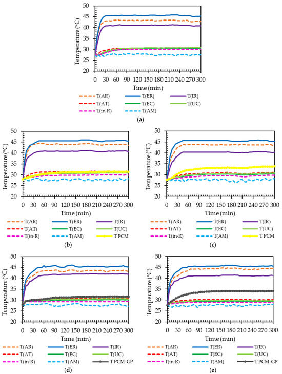
Figure 9.
Variation in temperature at different positions under temperature control at 45 °C: (a) No-PCM layer; (b) PCMC layer (0% GP) on ceiling board; (c) under roof sheet; (d) PCMC-10%GP layer on ceiling board; and (e) under roof sheet scenarios.
The temperature trends for the model without a PCM layer stabilized around 30 min at 45 °C and 50 min at 65 °C. This pattern, depicting an increasing time to achieve a steady state due to thermal energy absorption, mirrors the behavior observed in models incorporating the PCMc layer and the PCMc-10%GP layer in both the ceiling and beneath the roof positions, similar to the standard metal roof sheet outlined in Table 6. Specifically, models integrating the PCMc-10%GP layer beneath the roof position exhibited a substantial extension in the time to reach a steady temperature, approximately 30–35 min longer than the normal model (without the PCM layer) at each temperature condition, as detailed in Table 6. This delay in heat transmission from the exterior roof surface to the interior testing room, facilitated by the PCM integration into the roof structure, resulted in reduced heat transfer and interior room temperature. Such a reduction holds significant implications for energy conservation in buildings, underscoring the importance of this outcome.

Table 6.
Stabilization time for temperature readings in each model with and without integrated PCM layers.
3.3.3. The Average Inside Room Temperature
The average room interior temperatures (Tin-R) for each model under different controlled temperature settings are summarized in Table 7 and depicted in Figure 10. When the exterior roof surface temperature was controlled at 45 °C, Tin-R for the model without a PCM layer, the models with the PCMC layer (0% GP) at the ceiling and roof, and those with the PCMC-10%GP layer at the ceiling and roof, were approximately 30.0 °C, 29.8 °C, 29.5 °C, 29.3 °C, and 29.0 °C, respectively. The lowest Tin-R was recorded for the PCMC-10%GP layer at the roof. Compared to the model without a PCM layer, Tin-R for the models with the PCMC layer (0% GP) at the ceiling and roof, and the PCMC-10%GP layer at the ceiling and roof, were lower by approximately 0.67%, 1.67%, 2.33%, and 3.33%, respectively. Across different controlled temperature conditions, the trends in Tin-R for each model corresponded to the trends observed at the 45 °C controlled temperature, as detailed in Table 7 and presented in Figure 10. The inclusion of PCMC and PCMC-10%GP layers consistently resulted in reduced Tin-R compared to the test models without PCM in all of the controlled temperature conditions. Acknowledging the potential advantages, the incorporation of paraffin and paraffin–graphite composites as PCMs into the ceiling and roof sections can significantly reduce a building’s energy consumption and alleviate annual peak cooling demands. During the transition from a solid to a liquid state, phase change materials (PCMs) absorb heat from their surroundings, a phenomenon referred to as the melting process. The absorbed energy is stored as latent heat. Subsequently, when PCMs undergo solidification, shifting from a liquid to a solid state, they release the stored latent heat back into their surroundings. This advancement holds the potential to improve energy efficiency in buildings, making them more environmentally sustainable and economically viable.

Table 7.
The average indoor room temperature (Tin-R) under various temperature-controlled conditions.
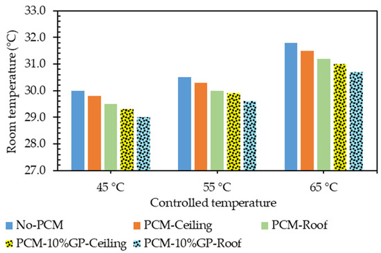
Figure 10.
Average indoor room temperature (Tin-R) for each controlled temperature condition.
Additionally, this study acknowledges several key limitations and considerations:
- Limited PCM representation: The investigation focused on three commercially available paraffins with specific melting points and densities, serving as representative PCMs. However, the chosen materials may not cover the full spectrum of PCMs used in similar applications, potentially leading to variations in thermal properties.
- Restricted testing model: The experiment utilized a controlled test model with specific dimensions and a fixed 40-degree angle between the metal roof and gypsum ceiling. While effective for demonstrating heat transfer within a confined space of 1 m3, this approach may not fully capture the complexities of larger and diverse architectural structures.
- Absence of real weather conditions data: The study lacks data on system performance under dynamic, real-time weather conditions. The findings are based on controlled environments, and a comprehensive assessment would benefit from data reflecting fluctuations in air temperature throughout the day.
- Limited practical insights: The research primarily addresses thermal conductance within the test enclosure, omitting practical complexities and expenses associated with implementing these systems in real architectural structures. Considerations such as maintenance requirements, installation logistics, and economic viability were not explored.
4. Conclusions
This research focused on the thermal behavior analysis of PCMs for building envelope applications, with a specific emphasis on paraffin-based PCMs and PCM–graphite composites. The findings from the study provide significant insights into the practical application of these materials for mitigating heat transfer in buildings.
- Thermal characteristics of PCMs without graphite powder: The thermal properties of three distinct paraffin waxes (PCMA, PCMB, PCMC) were analyzed using DSC. The study revealed unique phase transition temperature intervals and latent heat values for each PCM, essential for their effective application in building envelopes. PCMC, in particular, demonstrated promising thermal characteristics, with high latent heat values and a phase transition temperature range suitable for building applications in tropical regions.
- Thermal analysis of the PCM–graphite composites: PCM–graphite composites were prepared by combining paraffin-based PCMC with graphite powder at different weight ratios (10% and 20%). The DSC analysis showed that the addition of graphite powder did not significantly alter the chemical structure of the PCM. The PCM-10%GP composite exhibited a narrower phase transition temperature range, highlighting its potential for improved thermal performance while maintaining well-defined phase transition characteristics. The study emphasized that the effectiveness of a 10% weight ratio of graphite powder for enhancing the melting rate was 35.94% compared to PCMC without graphite powder.
- Application of PCM–graphite composites in building envelopes: The research explored the practical application of PCMC layers without graphite and PCMC–graphite composite layers in a building’s envelope, specifically in the ceiling and roof. Controlled temperature experiments were conducted, and temperature readings were collected at various critical points within the building model. The results demonstrated that the incorporation of PCMC and PCMC-10%GP layers consistently led to lower average room interior temperatures compared to models without the PCM under different controlled temperature conditions. The study highlighted the potential of paraffin and paraffin–graphite composites to reduce a building’s energy consumption and improve energy efficiency, making them environmentally sustainable and economically viable for building applications.
This research contributes valuable findings to the field of thermal energy storage and building envelope design, showcasing the potential of PCMC and PCMC–graphite composites for effective heat transfer mitigation in buildings. The identified optimal conditions for the PCMC-10%GP composite offer practical insights for applications in real-world building scenarios, paving the way for more energy-efficient and sustainable building designs.
Author Contributions
Conceptualization, A.T. and C.M.; Methodology, A.T., A.F. and C.M.; Formal analysis, A.T., A.F. and C.M.; Investigation, A.T., A.F. and C.M.; Resources, A.T.; Data curation, A.T. and C.M.; Writing—original draft preparation, A.T., A.F. and C.M.; Writing—review and editing, A.T.; Visualization, A.T.; Supervision, A.T.; Project administration, A.T.; Funding acquisition, A.T. All authors have read and agreed to the published version of the manuscript.
Funding
This research was funded by the Thailand Science Research and Innovation (TSRI) through the Fundamental Fund (2023), with support under grant number R2566B015.
Data Availability Statement
Data are contained within the article.
Acknowledgments
The authors would like to thank the Science Achievement Scholarship of Thailand (SAST), Faculty of Science, Naresuan University, and our research center for its valuable contributions.
Conflicts of Interest
The authors declare no conflict of interest.
References
- Dardouri, S.; Tunçbilek, E.; Khaldi, O.; Arıcı, M.; Sghaier, J. Optimizing PCM Integrated Wall and Roof for Energy Saving in Building under Various Climatic Conditions of Mediterranean Region. Buildings 2023, 13, 806. [Google Scholar] [CrossRef]
- Goldberg, M.H.; van der Linden, S.; Maibach, E.; Leiserowitz, A. Discussing Global Warming Leads to Greater Acceptance of Climate Science. Proc. Natl. Acad. Sci. USA 2019, 116, 14804–14805. [Google Scholar] [CrossRef] [PubMed]
- Shen, X.; Liu, B.; Jiang, M.; Lu, X. Marshland Loss Warms Local Land Surface Temperature in China. Geophys. Res. Lett. 2020, 47, e2020GL087648. [Google Scholar] [CrossRef]
- Han, H.; Ahn, S.W. Youth Mobilization to Stop Global Climate Change: Narratives and Impact. Sustainability 2020, 12, 4127. [Google Scholar] [CrossRef]
- Akeiber, H.; Nejat, P.; Majid, M.Z.A.; Wahid, M.A.; Jomehzadeh, F.; Famileh, I.Z.; Calautit, J.K.; Hughes, B.R.; Zaki, S.A. A Review on Phase Change Material (PCM) for Sustainable Passive Cooling in Building Envelopes. Renew. Sustain. Energy Rev. 2016, 60, 1470–1497. [Google Scholar] [CrossRef]
- Mano, C.; Thongtha, A. Efficiency of Electricity Production from Installed Generator on a Condensing Unit of an Air Conditioner. J. Adv. Res. Fluid Mech. Therm. Sci. 2019, 60, 2289–7879. [Google Scholar]
- Ma, L.; Luo, D.; Hu, H.; Li, Q.; Yang, R.; Zhang, S.; Li, D. Energy Performance of a Rural Residential Building with PCM-Silica Aerogel Sunspace in Severe Cold Regions. Energy Build. 2023, 280, 112719. [Google Scholar] [CrossRef]
- Masood, U.; Haggag, M.; Hassan, A.; Laghari, M. A Review of Phase Change Materials as a Heat Storage Medium for Cooling Applications in the Built Environment. Buildings 2023, 13, 1595. [Google Scholar] [CrossRef]
- Mano, C.; Thongtha, A.; Maneewan, S.; Punlek, C. Improvement of the Thermal Efficiency of Autoclaved Aerated Concrete by Black Powder. Sci. Asia 2021, 47S, 76–82. [Google Scholar] [CrossRef]
- Li, C.; Wen, X.; Cai, W.; Yu, H.; Liu, D. Phase Change Material for Passive Cooling in Building Envelopes: A Comprehensive Review. J. Build. Eng. 2023, 65, 105763. [Google Scholar] [CrossRef]
- Mahdi, M.S.; Mahood, H.B.; Campbell, A.N.; Khadom, A.A. Natural Convection Improvement of PCM Melting in Partition Latent Heat Energy Storage: Numerical Study with Experimental Validation. Int. Commun. Heat Mass Transfer 2021, 126, 105463. [Google Scholar] [CrossRef]
- Punlek, C.; Maneewan, S.; Thongtha, A. Phase Change Material Coating on Autoclaved Aerated Lightweight Concrete for Cooling Load Reduction. Materials 2017, 23, 1320. [Google Scholar] [CrossRef]
- Hughes, B.R.; Chaudhry, H.N.; Ghani, S.A. A Review of Sustainable Cooling Technologies in Buildings. Renew. Sustain. Energy Rev. 2011, 15, 3112–3120. [Google Scholar] [CrossRef]
- Wu, D.; Rahim, M.; El Ganaoui, M.; Bennacer, R.; Djedjig, R.; Liu, B. Dynamic Hygrothermal Behavior and Energy Performance Analysis of a Novel Multilayer Building Envelope Based on PCM and Hemp Concrete. Constr. Build. Mater. 2022, 341, 127739. [Google Scholar] [CrossRef]
- Ji, R.; Li, X. Numerical Analysis on the Energy Performance of the PCMs-Integrated Thermochromic Coating Building Envelopes. Build. Environ. 2023, 233, 110113. [Google Scholar] [CrossRef]
- Thongtha, A.; Khongthon, A.; Boonsri, T.; Hoy-Yen, C. Thermal Effectiveness Enhancement of Autoclaved Aerated Concrete Wall with PCM-Contained Conical Holes to Reduce the Cooling Load. J. Mater. 2019, 12, 2170. [Google Scholar] [CrossRef] [PubMed]
- Sun, X.; Zhang, Y.; Xie, K.; Medina, M.A. A Parametric Study on the Thermal Response of a Building Wall with a Phase Change Material (PCM) Layer for Passive Space Cooling. J. Energy Storage 2022, 47, 103548. [Google Scholar] [CrossRef]
- Jiang, W.; Liu, B.; Zhang, X.; Zhang, T.; Li, D.; Ma, L. Energy Performance of Window with PCM Frame. Sustain. Energy Technol. Assess. 2021, 45, 101109. [Google Scholar]
- Silva, T.; Vicente, R.; Rodrigues, F.; Samagaio, A.; Cardoso, C. Performance of a Window Shutter with Phase Change Material under Summer Mediterranean Climate Conditions. Appl. Therm. Eng. 2015, 84, 246–256. [Google Scholar] [CrossRef]
- Abden, M.J.; Tao, Z.; Pan, Z.; George, L.; Wuhrer, R. Inclusion of Methyl Stearate/Diatomite Composite in Gypsum Board Ceiling for Building Energy Conservation. Appl. Energy 2020, 259, 114113. [Google Scholar] [CrossRef]
- Gallardo, A.; Berardi, U. Experimental Evaluation of the Cooling Performance of Radiant Ceiling Panels with Thermal Energy Storage. Energy Build. 2022, 262, 112021. [Google Scholar] [CrossRef]
- Weinläder, H.; Körner, W.; Strieder, B. A Ventilated Cooling Ceiling with Integrated Latent Heat Storage—Monitoring Results. Energy Build. 2014, 82, 65–72. [Google Scholar] [CrossRef]
- Meng, E.; Wang, J.; Yu, H.; Cai, R.; Chen, Y.; Zhou, B. Experimental Study of the Thermal Protection Performance of the High Reflectivity-Phase Change Material (PCM) Roof in Summer. Build. Environ. 2019, 164, 106381. [Google Scholar] [CrossRef]
- Hu, J.; Yu, X. Adaptive Building Roof by Coupling Thermochromic Material and Phase Change Material: Energy Performance Under Different Climate Conditions. Constr. Build. Mater. 2020, 262, 120481. [Google Scholar] [CrossRef]
- Piselli, C.; Castaldo, V.L.; Pisello, A.L. How to Enhance Thermal Energy Storage Effect of PCM in Roofs with Varying Solar Reflectance: Experimental and Numerical Assessment of a New Roof System for Passive Cooling in Different Climate Conditions. Sol. Energy 2019, 192, 106–119. [Google Scholar] [CrossRef]
- Al-Yasiri, Q.; Szabó, M. Paraffin as a Phase Change Material to Improve Building Performance: An Overview of Applications and Thermal Conductivity Enhancement Techniques. Renew. Energy Environ. Sustain. 2021, 6, 38. [Google Scholar] [CrossRef]
- Chen, Q.; Wang, H.; Gao, H.; Wang, X.; Ma, B. Effects of Porous Silicon Carbide Supports Prepared from Pyrolyzed Precursors on the Thermal Conductivity and Energy Storage Properties of Paraffin-Based Composite Phase Change Materials. J. Energy Storage 2022, 56, 106046. [Google Scholar] [CrossRef]
- Yan, P.; Fan, W.; Yang, Y.; Ding, H.; Arshad, A.; Wen, C. Performance Enhancement of Phase Change Materials in Triplex-Tube Latent Heat Energy Storage System Using Novel Fin Configurations. Appl. Energy 2022, 327, 120064. [Google Scholar] [CrossRef]
- Zheng, H.; Wang, C.; Liu, Q.; Tian, Z.; Fan, X. Thermal Performance of Copper Foam/Paraffin Composite Phase Change Material. Energy Conv. Manag. 2018, 157, 372–381. [Google Scholar] [CrossRef]
- Iasiello, M.; Mameli, M.; Filippeschi, S.; Bianco, N. Metal Foam/PCM Melting Evolution Analysis: Orientation and Morphology Effects. Appl. Therm. Eng. 2021, 187, 116572. [Google Scholar] [CrossRef]
- Zhao, C.; Opolot, M.; Liu, M.; Bruno, F.; Mancin, S.; Hooman, K. Phase Change Behavior Study of PCM Tanks Partially Filled with Graphite Foam. Appl. Therm. Eng. 2021, 196, 117313. [Google Scholar] [CrossRef]
- Bashar, M.; Siddiqui, K. Experimental Investigation of Transient Melting and Heat Transfer Behavior of Nanoparticle-Enriched PCM in a Rectangular Enclosure. J. Energy Storage 2018, 18, 485–497. [Google Scholar] [CrossRef]
- Rawat, M.; Singh, R.N. A Study on the Comparative Review of Cool Roof Thermal Performance in Various Regions. Energy Build. Environ. 2022, 3, 327–347. [Google Scholar] [CrossRef]
- Rashid, F.L.; Al-Obaidi, M.A.; Dulaimi, A.; Bernardo, L.F.A.; Eleiwi, M.A.; Mahood, H.B.; Hashim, A. A Review of Recent Improvements, Developments, Effects, and Challenges on Using Phase-Change Materials in Concrete for Thermal Energy Storage and Release. J. Compos. Sci. 2023, 7, 352. [Google Scholar] [CrossRef]
- Kośny, J.; Thakkar, J.; Kamidollayev, T.; Sobkowicz, M.J.; Trelles, J.P.; Schmid, C.; Phan, S.; Annavajjala, S.; Horwath, P. Dynamic Thermal Performance Analysis of PCM Products Used for Energy Efficiency and Internal Climate Control in Buildings. Buildings 2023, 13, 1516. [Google Scholar] [CrossRef]
- Mano, C.; Thongtha, A. Enhanced Thermal Performance of Roofing Materials by Integrating Phase Change Materials to Reduce Energy Consumption in Buildings. J. Renew. Mater. 2021, 9, 495–506. [Google Scholar] [CrossRef]
- Khan, M.; Khan, M.M.; Irfan, M.; Ahmad, N.; Haq, M.A.; Khan, I.; Mousa, M. Energy Performance Enhancement of Residential Buildings in Pakistan by Integrating Phase Change Materials in Building Envelopes. Energy Rep. 2022, 8, 9290–9307. [Google Scholar] [CrossRef]
- Thongtha, A.; Janyoosuk, K.; Mano, C. Integration of Phase Change Material into Fiber Cement Roof for Reduction of Heat Accumulation in Buildings. Sci. Asia 2021, 47S, 83–89. [Google Scholar] [CrossRef]
- Yin, Z.; Zhang, X.; Huang, Z.; Liu, S.; Zhang, W.; Liu, Y.; Wu, X.; Fang, M.; Min, X. Paraffin/Expanded Graphite Phase Change Composites with Enhanced Thermal Conductivity Prepared by Implanted β-SiC Nanowires with Chemical Vapor Deposition Method. Mater. Res. Express 2018, 5, 025503. [Google Scholar] [CrossRef]
- Sathiyaraj, R.; Rakesh, R.; Mithran, N.; Venkatesan, M. Enhancement of Heat Transfer in Phase Change Material Using Graphite-Paraffin Composites. MATEC Web Conf. 2018, 172, 02001. [Google Scholar] [CrossRef][Green Version]
- Feng, L.; Wu, J.; Sun, W.; Cai, W. Effects of Pore Structure and Pore Size of Expanded Graphite on the Properties of Paraffin Wax/Expanded Graphite Composite Phase Change Materials. Energies 2022, 15, 4201. [Google Scholar] [CrossRef]
Disclaimer/Publisher’s Note: The statements, opinions and data contained in all publications are solely those of the individual author(s) and contributor(s) and not of MDPI and/or the editor(s). MDPI and/or the editor(s) disclaim responsibility for any injury to people or property resulting from any ideas, methods, instructions or products referred to in the content. |
© 2023 by the authors. Licensee MDPI, Basel, Switzerland. This article is an open access article distributed under the terms and conditions of the Creative Commons Attribution (CC BY) license (https://creativecommons.org/licenses/by/4.0/).
