Abstract
Carbon emission calculation during power transmission and substation construction provides valuable insights into the trend of carbon emissions and the development of low-carbon power grids. In this regard, this study divides the power transmission and substation construction process into production, transportation, and construction stages based on the sources of carbon emissions and employs a life cycle assessment to calculate the total carbon emissions using the carbon emission factor method for typical 500 kV projects. The results show that in the construction process the production stage contributes the most carbon emissions, with material and equipment production for power transmission accounting for 78% and 14% of the total emissions, respectively. The transportation and construction stage contribute 1% and 7% of the total emissions, respectively. For substations, material and equipment production contribute 67% and 30% of the total emissions, respectively. The transportation and construction phases contribute 1% and 2% of the total emissions. Through the qualitative and quantitative analysis of the carbon emission results, the construction scale and the topography and geology have significant impacts on carbon emissions from power transmission and substation projects. Finally, some targeted recommendations for carbon emission reduction for power transmissions and substations are proposed based on the influencing factors of each stage of the construction.
1. Introduction
In China, the energy sector is the main source of carbon emissions, with the power sector accounting for approximately 40% of carbon emissions [1]. Therefore, the development of a new type of green low-carbon power system is urgently required to achieve the strategic goals of “peak carbon dioxide emissions” and “carbon neutrality”. Carbon emission accounting constitutes a crucial basis for evaluating the efforts of “peak carbon dioxide emissions” and “carbon neutrality” goals, which can support the realization of the new power system [2].
Most carbon emissions from traditional power systems originate from the combustion of fossil fuels during power generation [3]. As a result, existing carbon emission accounting research in the power field primarily focuses on the power generation stage [4,5,6,7]. Consequently, research on carbon emissions during the construction stage of power transmission and transformation projects remains limited. In the future, the proportion of clean energy generation will continue to increase [8], leading to a significant reduction in carbon emissions during the power generation stage. However, the proportion of carbon emissions from the construction stage of power transmission and transformation projects will continue to grow in the overall emissions of the power system [9]. Therefore, conducting research on carbon emission accounting systems during the construction stage of power transmission and transformation projects is of great significance for establishing a robust data foundation for carbon emissions in the power system.
In existing research, accounting for carbon emissions during the construction of power transmission and transformation projects is relatively crude, both domestically and overseas, and carbon emissions have been primarily calculated using the building level alone. For example, Hu Yashan conducted a carbon accounting and analysis of the entire lifecycle of a substation by considering the carbon emission characteristics of the buildings and the substation processes [10,11]. However, the analysis overlooked the emissions caused by the construction activities. Moreover, a detailed calculation of carbon emissions during the production process of electrical equipment was also not conducted. Consequently, it seriously underestimates the calculation results [12]. Anders Arvesen and Gareth P. Harrison [13,14] evaluated the carbon footprint of power transmission systems in Norway and the UK, respectively, with an assessment approach for the entire life cycle. They calculated the carbon emissions of the power transmission systems based on energy and material carbon emission factors and verified that the widespread construction of infrastructure has a significant impact on climate change. Moreover, scholars have calculated greenhouse gas emissions from electrical infrastructure in other regions of Northern Europe [15,16]. However, carbon emission data from other countries have low reference values owing to differences in construction scale and technology.
In this study, some typical transmission lines and 500 kV substations are considered and the research’s objective is to analyze the carbon emission sources, define the accounting boundary, calculate the carbon emissions at each stage of the construction process, establish a carbon accounting model that is applicable to transmission line and substation construction, and analyze the factors that influence the calculation results. It can provide a reference for developing a carbon emission accounting system for the new power system.
2. Carbon Emission Accounting Method
Two main methods exist for accounting for greenhouse gas emissions, namely the calculation approach and the measurement approach. The calculation method can be further classified into the carbon emission factor approach and the material balance analysis approach. Among them, the measurement approach requires on-site measurement data of the emission sources, which provides accurate calculation results. However, obtaining such data is generally difficult and requires substantial investment. On the other hand, the material balance analysis approach has a simple model, but it involves the detailed recording and calculation of energy consumption and material flow during the activity process with a relatively narrow application scope. Given the complex nature and lengthy duration of activities involved in power transmission and substation construction projects coupled with the analysis of project volume and energy consumption, the feasibility of using the carbon emission factor method for their calculation is significant [17]. The carbon emission factor approach is widely used and simple to operate. Therefore, the carbon emission factor approach is adopted in this study to quantitatively account for carbon emissions from power transmission and substation construction. In accordance with the carbon emission factor approach, the basic formula for calculating the carbon emissions from substation construction is as follows:
where E represents carbon dioxide emissions, AD represents the data of activities that generate carbon emissions, EF represents the carbon emission factor per unit of substance, and GWP represents the global warming potential of the gas.
E = AD × EF × GWP
2.1. Carbon Emission Calculation Boundary
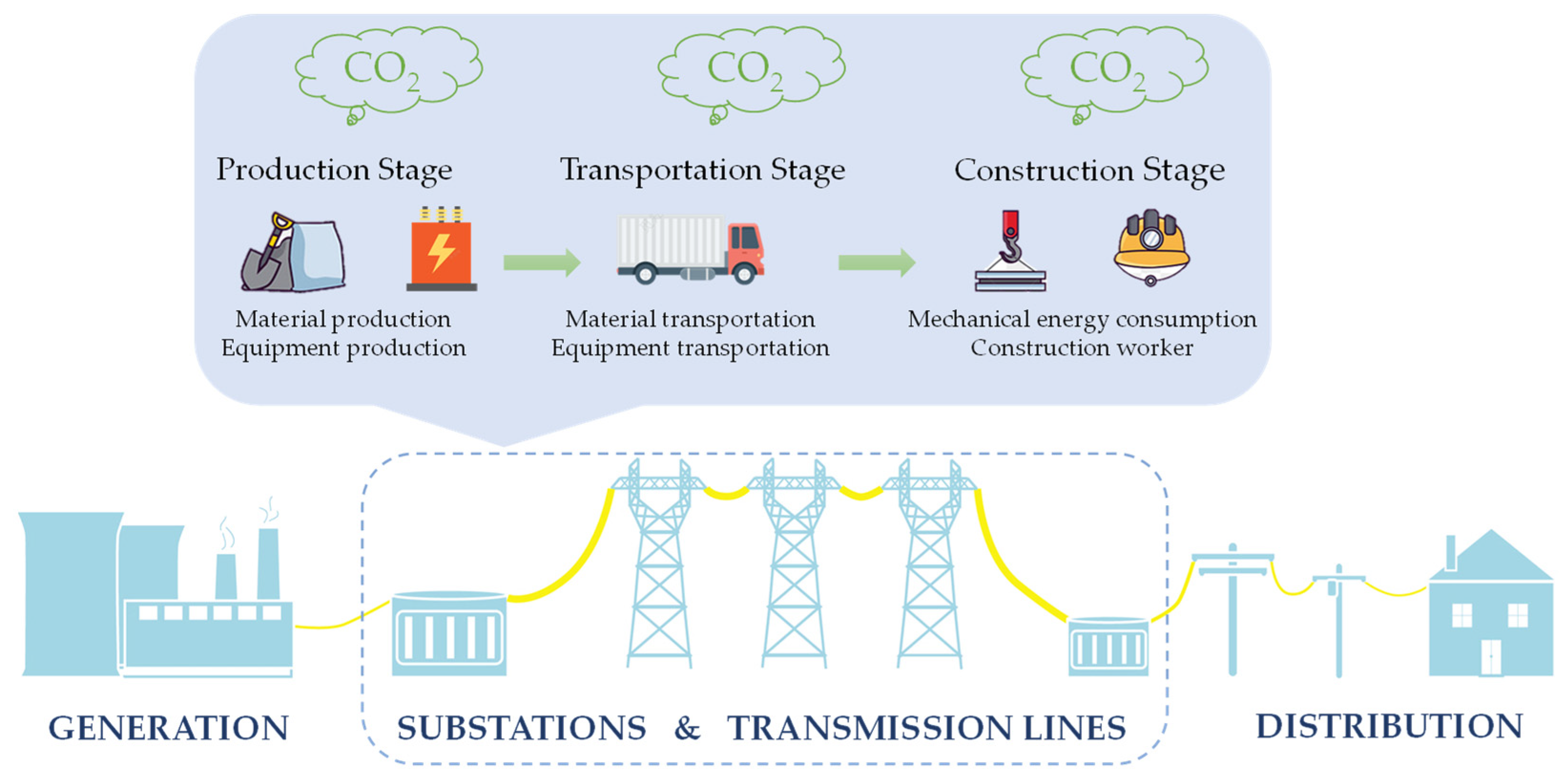
Clearly defining the scope of calculation is the key to carbon emission calculation based on the above approach. Accordingly, the accounting boundary is divided into three stages based on the characteristics of the power transmission and substation construction process of the production, transportation, and construction stages. The specific carbon emission activities involved in each stage are as follows:
- Production stage: the production of main civil engineering materials and electrical equipment, including the extraction and transportation of raw materials and energy;
- Transportation stage: the transportation of civil engineering materials and electrical equipment from the factory to the construction site;
- Construction stage: the energy consumption of mechanical operations and equipment in different processes and the energy consumption of construction workers.
Detailed carbon emission accounting boundaries and the inventory of power transmission and substation construction are shown in Figure 1 and listed in Table 1.
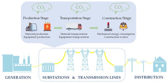
Figure 1.
Carbon emission accounting boundaries of power transmissions and substations.

Table 1.
Carbon emission inventory of construction.
2.2. Carbon Emission Calculation Method
2.2.1. Carbon Emissions from the Production of Civil Engineering Materials
The main types of civil engineering materials involved in the construction of substations include steel, concrete, stone materials, bricks, aluminum alloy, cement, ceramics, and mortar as well as iron parts. The formula for calculating carbon emission from the above materials can be expressed as follows:
where Qi represents the usage of the i-th civil engineering material in the substation and Fi represents the carbon emission factor of the i-th civil engineering material. Table 2 presents the numerical values of carbon emission factors for some materials along with the reference sources.
Table 2.
Carbon emission factors for the production of some materials.
2.2.2. Carbon Emissions from the Production of Electrical Equipment
The carbon emissions from the production of electrical equipment are referenced from Ref. [23]. The input-output analysis approach comprehensively considers both direct and indirect carbon emissions in the entire industry chain, enabling the tracking and quantification of carbon emissions from different industries, regions, and economic activities. Therefore, the input-output analysis approach is used to calculate the indirect carbon emissions from equipment production.
The input-output analysis approach reflects the relationships between various sectors of the economic system by preparing the input-output tables. The core of the carbon emission calculation model is the final demand matrix, the Leontief inverse matrix, and the carbon emission intensity matrix [24]. Specifically, the final demand matrix is obtained from the specific budget table of the target calculation object, the Leontief inverse matrix is obtained through the processing of the input-output table (IOT) budget, and the carbon emission intensity matrix is calculated using annual energy consumption data and specific economic data of the sectors. The Leontief inverse matrix represents the complete (including direct and indirect) demand of the production units’ final products for input sector products. Its expression is represented as (I-A)−1 where I is the identity matrix and A is the direct consumption coefficient matrix as obtained from the input-output table.
Considering the variation in the value of currency across different years, it is crucial to indicate the year of data collection when conducting statistical analysis to ensure uniformity in the currency value. The social discount rate can be set at 8% per year. The electrical equipment of power transmissions and substations primarily falls under sectors such as electrical motor and appliance manufacturing, machinery and equipment manufacturing, office machinery, and computer manufacturing. The formula for calculating the carbon emission from equipment production based on the input-output analysis approach is as follows:
where Qi represents the monetary acquisition cost of the i-th electrical equipment in the transmission line and substation, Fi represents the carbon emission factor of the sector to which the i-th electrical equipment belongs, and y represents the compilation year of the equipment purchase cost list (price level base year). Table 3 lists the carbon emission factors for the production of equipment in different sectors.
Table 3.
Carbon emission factors for the production of equipment in different sectors.
2.2.3. Carbon Emissions from Material Transportation
The weight or volume of the materials used can be derived based on the amount of activity of civil engineering materials during the production stage. In this study, the default transportation distance for materials is 40 km and the default mode of transportation is medium diesel trucks (8t). The formula for calculating the carbon emission from material transportation is as follows:
where Qi represents the usage of the i-th civil engineering material in the substation, Li represents the transportation distance for the i-th material, and Fi represents the carbon emission factor per unit of transportation for the i-th transportation mode of material. Table 4 presents the carbon emission factors for material transportation.
Table 4.
Carbon emission factors for the transportation of materials.
2.2.4. Carbon Emissions from Equipment Transportation
For the transportation of equipment, only the transportation of major equipment, such as the transformer, gas insulated switchgear (GIS), overhead line, and the insulator are considered. The default mode of transportation is a heavy diesel truck (46 t) for road transportation, with transportation volume measured through the weight multiplied by the distance (t·km). The default weight of the main transformer is 250 t/set. The calculation formula for the carbon emissions from equipment transportation is as follows:
where Qi denotes the weight of the i-th electrical equipment, Li denotes the transportation distance for the i-th electrical equipment, and Fi denotes the carbon emission factor per unit weight of transportation distance for the i-th mode of equipment transportation. Table 5 lists the carbon emission factors for equipment transportation.
Table 5.
Carbon emission factors for the transportation of equipment.
2.2.5. Carbon Emissions from Construction Energy Consumption
The carbon emissions from construction energy consumption of power transmission and substation projects primarily involves the estimation of the types and quantities of energy consumption in various processes. It enables us to obtain estimated carbon emissions based on energy consumption data. The types of energy consumed in each process can be estimated based on the number of machine units/shifts used during the construction process. The carbon emissions from construction energy consumption can be estimated using the following formula:
where Qi indicates the consumption of the i-th energy in the substation and Fi represents the carbon emission factor of the i-th energy. Table 6 lists the carbon emission factors of energy.
Table 6.
Carbon emission factors of energy.
2.2.6. Carbon Emissions from Construction Workers
A specific regulatory requirement does not exist for the area of temporary facilities in the construction budget. Generally, the cost is determined proportionally. As the provision of temporary facilities is related to the number of workers, the calculation of carbon emissions from temporary buildings can be related to the number of workdays in the construction budget in order to use the per unit workday carbon emission factor approach to calculate the carbon emissions from temporary buildings. The formula for calculating the carbon emissions from workers’ daily life is as follows:
where Qi represents the number of construction workdays for the i-th project and Fi represents the carbon emission factor for temporary facilities during the construction phase of the i-th project. Table 7 lists the carbon emission factors of temporary facilities in different climatic regions.
Table 7.
Carbon emission factors of temporary facilities during the construction stage in different climatic regions.
3. The Calculation Results of Typical Projects
3.1. Data Collection from the Projects
In this study, detailed engineering data were collected on the construction process of four typical 500 kV transmission lines and related substation projects in Zhejiang Province. Carbon emission accounting and analysis were conducted based on the obtained data.
Table 8 and Table 9 present information regarding four transmission lines and respective substations. The transmission lines have equivalent transmission capacities, with the substations comprising capacities of 1000 MVA and 2000 MVA.
Table 8.
Construction information and data collection of power transmission projects.
Table 9.
Construction information and data collection of substation projects.
3.2. Calculation of Carbon Emissions from Power Transmission and Substation Projects
Based on the construction data collected from several projects, taking missing data for individual projects into consideration, the average value of similar projects or linear treatment based on the scale was used in the analysis. Based on the carbon emission calculation formulas for each stage, the carbon emissions from material production, equipment production, material transportation, equipment transportation, construction energy consumption, and workers’ energy consumption during the construction of the four projects were calculated. Finally, the carbon emissions of each stage were summed up to calculate the total carbon emissions from the construction of power transmissions and substations. The results are shown in Table 10 and Table 11.
Table 10.
Typical 500 kV power transmission carbon emissions/t CO2.
Table 11.
Typical 500 kV substation carbon emissions/t CO2.
Table 10 presents the carbon emissions during the construction of transmission lines. The calculated results of carbon emissions from the transmission lines differ, with emissions of 10,525.10, 22,798.77, 103,168.7, and 88,958.06 tons for L1, L2, L3, and L4, respectively. Despite the relatively small differences in transmission capacity among the four lines, the length of the transmission lines may have a significant impact on the carbon emissions. The emissions from the transportation and construction phases during the construction of the transmission lines are significantly lower than those from the production phase.
Table 11 displays the carbon emissions during the construction of four substations. The differences in carbon emissions are relatively small, with emissions of 25,341.78, 25,589.84, 35,578.18, and 38,148.82 tons for S1, S2, S3, and S4, respectively. As shown in Table 11, the larger the rated capacity, the higher the carbon emissions. Additionally, similar to the transmission lines, the carbon emissions from the transportation and construction phases during the construction of the substations are significantly lower than those from the production phase.
3.3. Analysis of Carbon Emission Calculation Results
The results of carbon emissions from each part of the power transmission and substation projects are illustrated in Figure 2 and Figure 3.
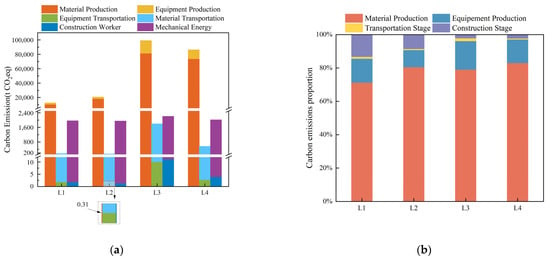
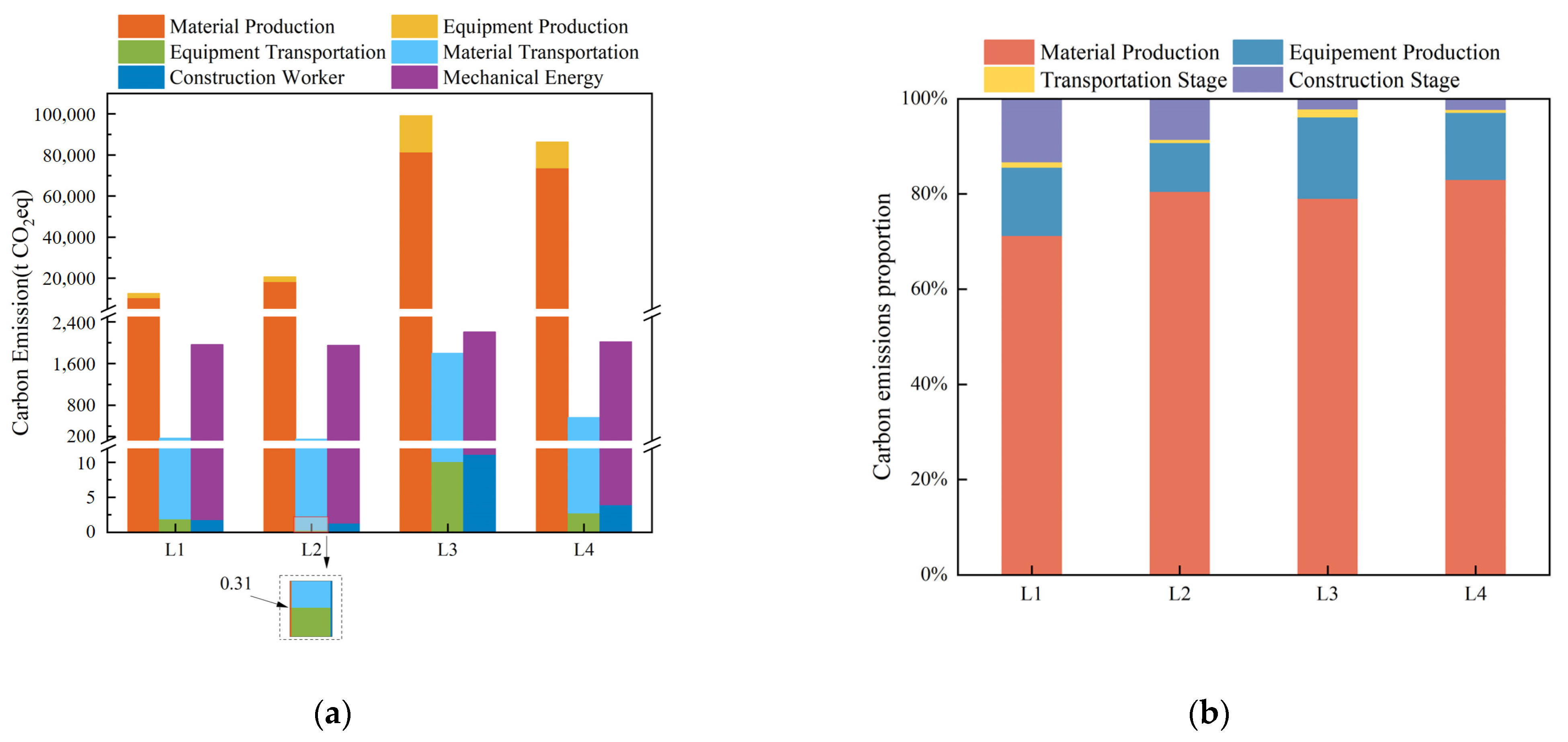
Figure 2.
(a) Total carbon emissions from power transmission construction, with the carbon emissions from the equipment transportation of L2 shown in the zoomed-in area; (b) carbon emission proportion from power transmission construction of each stage.
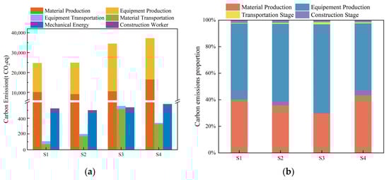
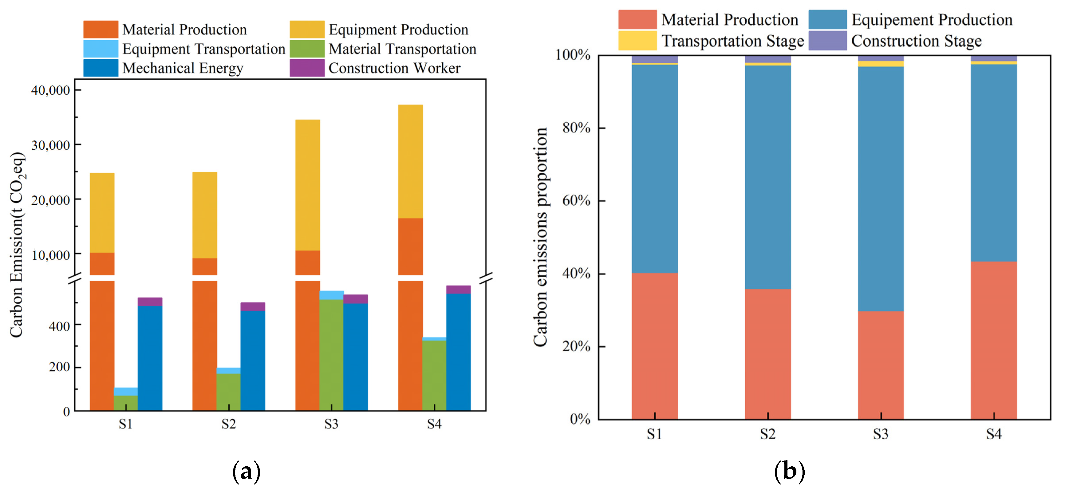
Figure 3.
(a) Total carbon emissions from substation construction; (b) carbon emission proportion from substation construction of each stage.
As shown in Figure 2, material production contributes the most to carbon emissions, with the average carbon emissions of the lines accounting for 78% of the total carbon emissions and the line L4 for 83%. It is followed by equipment production, which on average accounts for 14% of the total carbon emissions. The carbon emission sum of the raw material production and the equipment production of the power transmission project accounts for 92%. The transportation stage and construction stage account for 1% and 7% of carbon emissions, respectively. The carbon emissions contributed by mechanical operations during the construction stage are relatively stable. It is worth noting that there is a smaller amount of equipment transportation carbon emissions, whose proportion is almost zero, because the equipment is mainly cables and insulators and the transportation weight and the distance of transportation are relatively small.
As shown in Figure 3, equipment production contributes the most to carbon emissions, with the average carbon emissions of the substations accounting for 60% of the total carbon emissions. The carbon emissions from equipment production accounts for 67.1% of the total carbon emissions of the Jiangbin Substation Project (S3). It is followed by the production of raw materials, which on average accounts for 37% of the total carbon emissions. The main sources for such carbon emissions include the production of two building materials, namely steel and concrete, contributing over 60% of the material production carbon emissions. Equipment production and raw material production contribute the majority of carbon emissions, with the average sum of their proportions reaching 97%, which is consistent with the results of the substation project. The transportation stage and construction stage account for 1% and 2% of carbon emissions, respectively. The major carbon emissions from the former originate from the transportation of civil engineering materials; there is significant variation in carbon emissions from material transportation among different substations. In addition, for equipment transportation, only the carbon emissions from the main equipment, such as transformers and GIS, are considered. This results in a smaller amount of carbon emissions. The major carbon emissions from the latter originate from the energy consumption of mechanical operations and the carbon emissions during the construction stage of different substations are relatively stable.
4. Discussion
4.1. Analysis of Factors Affecting Carbon Emissions
Based on the calculation data of carbon emissions, differences exist in the carbon emissions from 500 kV power transmissions and substations. Owing to the fact that the production stage contributes the highest carbon emissions during the construction process, this study focuses on the analysis of the carbon emissions from material production and equipment production. An analysis of the differences in carbon emission results was performed based on factors such as construction scales and terrain conditions.
For power transmission, the significant differences in carbon emissions are a result of the varying lengths of construction projects and the diverse topography of the areas where the lines are constructed. As depicted in Figure 1, longer power transmission lines result in higher carbon emissions. It is evident that as the distance of the lines increases, the requirement for construction materials and electrical equipment, such as overhead lines and pylons, also increases, leading to higher carbon emissions. In addition to the impact of transmission line length, this study qualitatively analyzes the terrain of projects L1 and L4. It is evident from Table 12 that terrain significantly affects the carbon emission intensity of the line projects (carbon emissions per unit length of the line, i.e., total carbon emissions divided by the line length). When the proportion of marshy terrain is high in the construction area of the lines, the carbon emissions from the construction projects are greater. This is due to the need for more construction materials and raw materials to establish foundations in marshy terrain necessitating additional transportation services for raw materials and energy for construction machinery, thereby resulting in additional carbon emissions.
Table 12.
Carbon emission intensity and topography of some transmission line projects.
Regarding the equipment production process of the substations, the carbon emissions from equipment production increase accordingly as the rated capacity increases. For instance, the carbon emissions from the equipment production process of a 2000 MVA substation are approximately 7200 t higher than those of a 1000 MVA substation. Additionally, a certain correlation exists between the number of outgoing lines and the carbon emissions from the equipment production process in a substation. For example, both S3 and S4 are 2000 MVA substations, but S3 has three additional 500 kV outgoing lines compared with S4 from Table 13, resulting in an increase of 3200 t in carbon emissions from the equipment production process of the former. However, the number of outgoing lines is not the only influencing factor. Since the carbon emission accounting from the equipment production process is made using the input-output analysis approach, the currency value may vary from year to year, correlating the carbon emissions to the year the substation was constructed. For example, S1 has more 220 kV outgoing lines than S2, while S2 was constructed earlier than S50001, which has a lower monetary value, so the carbon emissions of S1 are lower than those of S2.
Table 13.
Number of substation outgoing lines and the year built.
For the material production process of substations and based on the geotechnical survey reports of the substations, all four substation sites are located on plains, making it difficult to perform a correlation analysis. However, variations exist in the topographical and geotechnical descriptions among the substations from Table 14.
Table 14.
Substation terrain description.
By ignoring the impact of the substation-rated capacity on the carbon emissions of the material production process and based on the analysis of the impact of the carbon emissions in the material production process from the substation terrain, more sand, cement, steel, and other raw materials are required for constructing the foundation because of complex terrain and complex geology. Consequently, additional raw material transportation services and energy are required for operating the construction machinery, resulting in additional carbon emissions.
For substation material and equipment transportation, the longer the transportation distance, the greater the carbon emissions generated by the transportation vehicles. In the substation construction stage, the complexity of the terrain and efficiency of mechanical operations have an impact on energy consumption during construction, thereby affecting the carbon emissions of the process.
4.2. Analysis of Carbon Emission Reduction in Substation Project Construction
Based on the carbon emission calculation results above, it is evident that raw material production and equipment production account for over 90% of the carbon emissions from power transmission and substation projects. Therefore, for the material production stage of future construction projects, we should adhere to the principle of “green design”, avoid sites with complex terrain and topography, and consider a green layout of the construction site. Environmentally friendly plants can be chosen based on the local conditions. For the equipment production stage, the use of low-carbon and efficient raw materials should be prioritized along with electrical equipment with a long service life, low maintenance requirements during its lifecycle, a small footprint, low energy consumption, and environmentally friendly features. For example, Hitachi Energy has supplied two 110 kV, 63 MVA EconiQ power transformers to China’s largest grid operator the State Grid Corporation of China for a substation project underway in Jiangsu Province on China’s east coast [25].
For the transportation stage, it is recommended that in the future planning and designing of power transmission and substation projects the local sourcing of materials should be prioritized. If it is infeasible, the nearest supply points in nearby cities with the shortest transportation distances should be selected. For the transportation of raw materials and equipment, the transportation mode with the least carbon emissions should be selected based on actual conditions. Furthermore, the most reasonable transportation routes should be carefully considered to effectively reduce the carbon emissions generated during transportation.
For the construction stage, information technology should be utilized to accurately control the operation of machinery, thereby improving operation efficiency and reducing operation energy consumption. For example, in the Fuzhou–Xiamen Project, with 91.3% of the line traversing mountainous terrain, the mechanization rate of line foundation construction reached 39% and all tower assemblies were carried out using ground pole clamps or mobile cranes. The project advances the intelligentization of construction machinery and tools and creates an intelligent manufacturing chain for main equipment [26].
5. Conclusions
In this study, the carbon emission factor approach was selected to calculate carbon emissions during the construction process of transmission lines and substations. A carbon emission calculation model was established for power transmission and substation projects and carbon emissions during the construction process of typical 500 kV transmission lines and substations were quantified. The conclusions that can be drawn are as follows:
- The total carbon emissions from the construction of typical 500 kV transmission lines are 1111.03 ± 530.7988 t per kilometer. During the production stage, the average carbon emissions account for 92% of the total carbon emissions, with 78% contributed by material production and 14% by equipment production. The transportation stage accounts for an average of 1% of the total emissions, while the construction stage contributes 7% on average. The total carbon emissions from the construction of typical 500 kV substation projects are (31,164.66 ± 6664.388) t. During the production stage, average carbon emissions account for 97% of the total carbon emissions. Among them, raw material production and equipment production contribute 37% and 60% of the total carbon emissions, respectively, the transportation stage, on average, accounts for 1% of the total carbon emissions on average, and the construction stage accounts for 2% of the total carbon emissions on average;
- Transmission line length and terrain conditions are crucial influencing factors for the carbon emissions of power transmission projects. Under the scale effect of line projects, the longer the line length, the more electrical equipment and civil engineering materials are required, thus increasing carbon emissions. Electrical wiring forms and terrain conditions are crucial influencing factors for the carbon emissions of substation projects. Under the scale effect of substation projects, the larger the rated capacity and the greater the outgoing lines, the more electrical equipment is required, thus increasing carbon emissions. Moreover, complex terrain and topography require more civil engineering materials, leading to the increased transportation of raw materials and energy consumption for construction machinery, thereby generating higher carbon emissions for transmission lines and substations;
- To reduce carbon emissions in power transmission and substation construction projects in the future, it is necessary to select materials that are resource-efficient, energy-efficient, have a longer service life, and have better utilization efficiency and impact. Additionally, selecting shorter and more efficient transportation routes can reduce implicit energy consumption. Accordingly, the overall green planning of transmission network projects can be implemented focusing on the goals of being green, being low-carbon, energy conservation, and emission reduction.
Author Contributions
Conceptualization, T.L. and Z.W.; methodology, T.L.; validation, C.C., H.C. and H.Z.; formal analysis, T.L.; investigation, Z.W.; resources, C.C.; data curation, H.C.; writing—original draft preparation, T.L.; writing—review and editing, Z.W.; visualization, C.C.; supervision, H.Z.; project administration, T.L.; funding acquisition, Z.W. All authors have read and agreed to the published version of the manuscript.
Funding
This research was funded by State Grid Zhejiang Electric Power Co., Ltd., grant number KJCB2022001.
Data Availability Statement
The data can be made available on request.
Conflicts of Interest
Authors Ti Liu, Zhen Wu, Cong Chen, and Huan Chen were employed by the company State Grid Zhejiang Electric Power Co., Ltd., Construction Company. The remaining author declares that the research was conducted in the absence of any commercial or financial relationships that could be construed as a potential conflict of interest.
References
- Luo, F.; Guo, Y.; Yao, M.; Cai, W.; Wang, M.; Wei, W. Carbon emissions and driving forces of China’s power sector: Input-output model based on the disaggregated power sector. J. Clean. Prod. 2020, 268, 121925. [Google Scholar] [CrossRef]
- Shu, Y.B.; Zhang, L.Y.; Zhang, Z.Z.; Wang, Y.H.; Lu, G.; Yuan, B.; Xia, P. Carbon peak and carbon neutrality path for China’s power industry. Strateg. Study Chin. Acad. Eng. 2021, 23, 1–14. [Google Scholar] [CrossRef]
- Kang, C.; Zhou, T.; Chen, Q.; Wang, J.; Sun, Y.; Xia, Q.; Yan, H. Carbon Emission Flow from Generation to Demand: A Network-Based Model. IEEE Trans. Smart Grid 2015, 6, 2386–2394. [Google Scholar] [CrossRef]
- Ma, C.-Q.; Ren, Y.-S.; Zhang, Y.-J.; Sharp, B. The allocation of carbon emission quotas to five major power generation corporations in China. J. Clean. Prod. 2018, 189, 1–12. [Google Scholar] [CrossRef]
- Fang, T.; Fang, D.; Yu, B. Carbon emission efficiency of thermal power generation in China: Empirical evidence from the micro-perspective of power plants. Energy Policy 2022, 165, 112955. [Google Scholar] [CrossRef]
- Ge, Z.; Geng, Y.; Wei, W.; Jiang, M.; Chen, B.; Li, J. Embodied carbon emissions induced by the construction of hydropower infrastructure in China. Energy Policy 2023, 173, 113404. [Google Scholar] [CrossRef]
- Orfanos, N.; Mitzelos, D.; Sagani, A.; Dedoussis, V. Life-cycle environmental performance assessment of electricity generation and transmission systems in Greece. Renew. Energy 2019, 139, 1447–1462. [Google Scholar] [CrossRef]
- Wei, W.; Zhang, P.; Yao, M.; Xue, M.; Miao, J.; Liu, B.; Wang, F. Multi-scope electricity-related carbon emissions accounting: A case study of Shanghai. J. Clean. Prod. 2020, 252, 119789. [Google Scholar] [CrossRef]
- Wei, W.; Li, J.; Chen, B.; Wang, M.; Zhang, P.; Guan, D.; Meng, J.; Qian, H.; Cheng, Y.; Kang, C.; et al. Embodied greenhouse gas emissions from building China’s large-scale power transmission infrastructure. Nat. Sustain. 2021, 4, 739–747. [Google Scholar] [CrossRef]
- Liu, X.; Zhang, J.; Hu, Y.; Liu, J.; Ding, S.; Zhao, G.; Zhang, Y.; Li, J.; Nie, Z. Carbon Emission Evaluation Method and Comparison Study of Transformer Substations Using Different Data Sources. Buildings 2023, 13, 1106. [Google Scholar] [CrossRef]
- Hu, Y.; Zhuang, D.; Zhu, K.; Shi, X. A Comparative Study on Lifecycle Carbon Emissions of Concrete Structure and Steel Structure Substations. Build. Sci. 2022, 38, 275–282. [Google Scholar]
- Wei, W.; Wu, X.; Li, J.; Jiang, X.; Zhang, P.; Zhou, S.; Zhu, H.; Liu, H.; Chen, H.; Guo, J.; et al. Ultra-high voltage network induced energy cost and carbon emissions. J. Clean. Prod. 2018, 178, 276–292. [Google Scholar] [CrossRef]
- Harrison, G.P.; Maclean, E.J.; Karamanlis, S.; Ochoa, L.F. Life cycle assessment of the transmission network in Great Britain. Energy Policy 2010, 38, 3622–3631. [Google Scholar] [CrossRef]
- Arvesen, A.; Hauan, I.B.; Bolsoy, B.M.; Hertwich, E.G. Life cycle assessment of transport of electricity via different voltage levels: A case study for Nord-Trondelag county in Norway. Appl. Energy 2015, 157, 144–151. [Google Scholar] [CrossRef]
- Jones, C.I.; McManus, M.C. Life-cycle assessment of 11 kV electrical overhead lines and underground cables. J. Clean. Prod. 2010, 18, 1464–1477. [Google Scholar] [CrossRef]
- Jorge, R.S.; Hertwich, E.G. Grid infrastructure for renewable power in Europe: The environmental cost. Energy 2014, 69, 760–768. [Google Scholar] [CrossRef]
- Gao, H.; Wang, X.; Wu, K.; Zheng, Y.; Wang, Q.; Shi, W.; He, M. A Review of Building Carbon Emission Accounting and Prediction Models. Buildings 2023, 13, 1617. [Google Scholar] [CrossRef]
- Peng, B.; Tong, X.; Cao, S.; Li, W.; Xu, G. Carbon Emission Calculation Method and Low-Carbon Technology for Use in Expressway Construction. Sustainability 2020, 12, 3219. [Google Scholar] [CrossRef]
- Li, L.; Chen, K. Quantitative assessment of carbon dioxide emissions in construction projects: A case study in Shenzhen. J. Clean. Prod. 2017, 141, 394–408. [Google Scholar] [CrossRef]
- Zhang, Y.; Yan, D.; Hu, S.; Guo, S. Modelling of energy consumption and carbon emission from the building construction sector in China, a process-based LCA approach. Energy Policy 2019, 134, 110949. [Google Scholar] [CrossRef]
- Nie, S.; Zhou, J.; Yang, F.; Lan, M.; Li, J.; Zhang, Z.; Chen, Z.; Xu, M.; Li, H.; Sanjayan, J.G. Analysis of theoretical carbon dioxide emissions from cement production: Methodology and application. J. Clean. Prod. 2022, 334, 130270. [Google Scholar] [CrossRef]
- Liu, C.; Zhu, C.; Bai, G.; Quan, Z.; Wu, J. Experimental Investigation on Compressive Properties and Carbon Emission Assessment of Concrete Hollow Block Masonry Incorporating Recycled Concrete Aggregates. Appl. Sci. 2019, 9, 4870. [Google Scholar] [CrossRef]
- Wei, W.; Wang, M.; Zhang, P.; Chen, B.; Guan, D.; Shao, S.; Li, J. A 2015 inventory of embodied carbon emissions for Chinese power transmission infrastructure projects. Sci. Data 2020, 7, 318. [Google Scholar] [CrossRef] [PubMed]
- Zhang, Q.; Fang, K.; Xu, M.; Liu, Q. Review of Carbon Footprint Research Based on Input-Output Analysis. J. Nat. Resour. 2018, 33, 696–708. [Google Scholar]
- Hitachi Energy Equips Zero Carbon Substation with Transformers. Available online: https://www.tdworld.com/substations/article/21237773/hitachi-energy-equips-zero-carbon-substation-with-transformers (accessed on 21 December 2023).
- The State Grid Corporation of China: Fuzhou-Xiamen 1000 kV Ultra-High Voltage AC Project Commences Operation. Available online: https://www.digitaljournal.com/pr/news/getnews/the-state-grid-corporation-of-china-fuzhou-xiamen-1000-kv-ultra-high-voltage-ac-project-commences-operation-#ixzz8MVjTkxWL (accessed on 21 December 2023).
Disclaimer/Publisher’s Note: The statements, opinions and data contained in all publications are solely those of the individual author(s) and contributor(s) and not of MDPI and/or the editor(s). MDPI and/or the editor(s) disclaim responsibility for any injury to people or property resulting from any ideas, methods, instructions or products referred to in the content. |
© 2024 by the authors. Licensee MDPI, Basel, Switzerland. This article is an open access article distributed under the terms and conditions of the Creative Commons Attribution (CC BY) license (https://creativecommons.org/licenses/by/4.0/).