1. Introduction
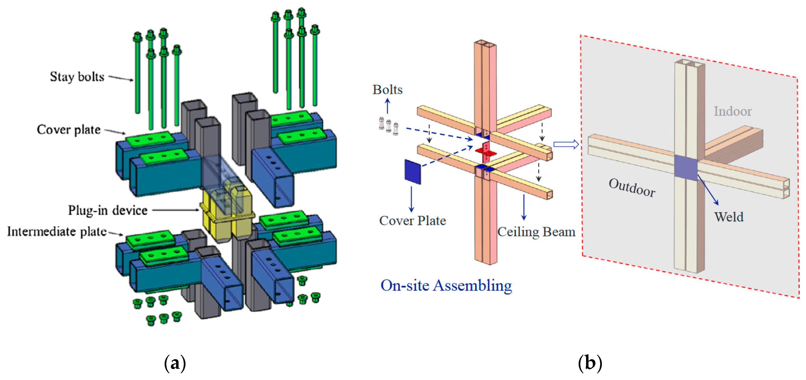
In March 2022, the Ministry of Housing and Urban–Rural Development of the People’s Republic of China issued the 14th five-year plan for building energy conservation and the green building development plan, which clarified the development goal that prefabricated buildings will account for more than 30% of new buildings by 2025. A modular building is composed of modular units, as shown in
Figure 1a. It is a highly integrated prefabricated building in the advanced stage of building industrialization, and its prefabrication rate can often reach more than 85%. The modular steel building (MSB) mainly adopts cold-formed thin-walled steel structure members, and its predecessor is the container house construction system that quickly builds temporary buildings by transforming abandoned containers or building new box houses. However, traditional container houses rarely have structural research support, and it is difficult to form construction standards and cannot develop in the direction of multi-story and high-rise buildings. Therefore, the multi-story MSB has ushered in a good development opportunity with a series of advantages, such as a high degree of assembly and fast construction speed.
The inter-module connection (IMC), as shown in
Figure 1b, is one of the key technologies that restrict the development of MSBs in multi-story and high-rise building systems. The reliability of the connections between modules directly affects the overall performance of the structure. Lacey et al. [
1,
2,
3] sorted out 14 existing IMCs and 12 types of bolted IMCs and expounded that the force–displacement behavior of IMCs in MSBs is established by a combination of theoretical, experimental, and numerical analyses. The simplified connection behavior for the analysis and design of the overall structure is discussed, and the existing experimental research methods for IMCs are deeply summarized. Chen et al. [
4] comprehensively summarized the key technical issues related to the structural stability and robust performance of multi-story, prefabricated, volumetric, modular steel construction and put forward the technical challenges facing the development of modular buildings to high-rise buildings. An updated summary of 41 existing IMC details—which were classified based on the key component: reinforcing rod, connection blocs, bolts, self-centering rubber slider device, and viscoelastic rubbers and SMA bolts—was presented. The research status of IMCs from different aspects and levels is also systematically reviewed [
5,
6,
7,
8,
9].
There are some studies on innovative IMCs at present. Chen et al. [
10,
11] proposed an innovative IMC configuration with an intermediate plug-in device and a beam-to-beam bolt system. Experimental tests and numerical analyses were conducted on T-shaped and cross-shaped specimens, and the static performance, hysteretic performance, skeleton curves, ductile performance, energy dissipation capacity, and stiffness degradation patterns of the IMC were obtained. The results showed that the gap between the upper and bottom columns can influence the deformation patterns and distribution of bending loads; the weld quality at the connection is critical to ensure overall safety; and stiffeners and the stiffness of the beam can also influence the performance of the connection. Deng et al. [
12,
13] proposed a bolted IMC with a welded cover plate. Tests on T-shaped and cross-shaped specimens were conducted under a monotonic and cyclic load. The seismic performance, including the initial rotational stiffness, moment resistance, ductility, and energy dissipation, were carefully evaluated. The proposed connection was classified as a semi-rigid connection, and its mechanical model and design recommendations were presented. Zhang et al. [
14] proposed a beam-to-beam IMC with a cross-shaped plug-in connector inside the adjacent columns, combined with hinged diagonal self-centering haunch braces. The results showed that the self-centering haunch braces significantly improved the seismic performance of the IMC and achieved functional recoverability after earthquakes. Lacey et al. [
15] proposed a novel interlocking IMC, which combines structural bolts with interlocking elements. Experimental study was conducted to investigate the shear force–slip behavior, and the effects of the interlocking elements, bolt preload, hole tolerance, and fabrication and assembly tolerance on the shear behavior were evaluated and discussed. Sendanayake et al. [
16,
17] proposed a column-to-column IMC and conducted experimental tests on the column-to-column splicing joint under a monotonic and cyclic load. The experimental study revealed that the IMCs display superior dynamic behavior with respect to response parameters, such as moment-carrying capacity, energy dissipation, and ductility. Kashan et al. [
18,
19] proposed a new type of bolted IMC with a tenon-gusset plate as the horizontal connection and long beam bolts as the vertical connection. Numerical study results revealed that the length of the column tenon has an obvious effect while the gap between modules showed a marginal effect on the load-carrying capacity and structural behavior. A simplification of the detailed IMC was performed to analyze the seismic performance of MSBs.
There are some deficiencies in the existing IMCs. From the perspective of mechanical performance: (1) The stiffness and bearing capacity of the unreinforced connection core area are insufficient. (2) The column ends of the beam-to-beam connection are not directly connected, which is easy to cause discontinuous load transfer. From the perspective of installation difficulty and cost: (1) On-site welding is more time-consuming and laborious than bolting. (2) The use of through bolts and threaded rods limits the form of beam and column sections and increases the difficulty of construction. From the perspective of research levels: (1) Theoretical research and design recommendations are inadequate. (2) Differences occur in experimental tests. For example, a single tensile or shear test is not enough to accurately reflect the real performance of the connection in the overall structure. In view of the above deficiencies, this study proposes an innovative IMC using bolted end plates of columns with a cross-shaped plug-in connector and provides its mechanical model and design recommendations in combination with finite element analysis for mechanical performance, including the flexural bearing capacity, shear capacity of the panel zone, and initial rotation stiffness. In addition, the panel zone volume modified factor and initial rotational stiffness modified factor are proposed for calculating the shear capacity of the panel zone and rotational stiffness. This study can provide the research basis and guidance for the design practice for IMCs in MSBs.
2. Connection Configuration
2.1. Proposed Configuration
The details of the proposed IMC and its assembling process are shown in
Figure 2. The connection consists of the following seven parts: (1) Columns (gray part in the figure) are made of cold-formed thin-walled square steel tubes; (2) Beams (white part in the figure), including the floor beam and ceiling beam, as shown in
Figure 1b, are made of thin-walled H-shaped steel or rectangular steel tubes; (3) The end plate of the column (blue part in the figure) has an opened cross-shaped hole to match the plug-in connector; (4) The cross-shaped plug-in connector (red part in the figure) is composed of a flange plate and eight tenons with an end-corner cutting for easy installation; (5) The bolts (yellow part in the figure) are high-strength bolts to connect the upper and lower columns; (6) The cover plate (green part in the figure) is used to connect the left and right columns; (7) The one-side bolts (cyan part in the figure) are used to fix the cover plates.
IMCs can be classified as external, internal, and corner connections, as shown in
Figure 1b. The proposed connection is a typical internal connection with the obvious features of eight columns and sixteen beams. The installation process is as follows: modules are prefabricated in the factory, with the beam and end plate welded to the column; subsequently, the specially manufactured connector is welded from several steel plates and beveled at the end of the formed tenons; then, the modules are assembled on-site, using the connector to locate and connect, and bolted vertically with high-strength bolts; finally, adjacent columns are connected horizontally with cover plates and one-side bolts.
2.2. Configuration Comparison
Compared with the existing IMCs proposed by Chen et al. [
10,
11] and Deng et al. [
12,
13], the proposed IMC in this study has some progress. The former is a type of beam-to-beam connection with a high-tensile-strength bolting system and has a cast plug-in device with square tube heads to strengthen the core area, as shown in
Figure 3a. The proposed IMC in this study is a type of column-to-column connection, and it better ensures the continuity of vertical load transfer compared to the beam-to-beam connection. The proposed IMC can replace more types of beam sections than connections using a high-tensile-strength bolting system. In addition, the cross-shaped plug-in connector provides a more stiffener-like effect than the plug-in device with square tube heads. The latter is an external connection with a welded cover plate, as shown in
Figure 3b. The form of the external welded cover plate makes this connection unsuitable for internal connections, and it is not easy to realize the function of module disassembly and reuse. The proposed IMC in this study avoids the above inadaptability very well, and the form of the full bolt connection reduces the construction burden and achieves a higher assembly rate.
The proposed IMC has the following highlights: (1) The configuration is simple, while the horizontal load and vertical load are clearly transferred through the connector. (2) The cross-shaped plug-in connector plays a role in reinforcing the core area of the connection, similar to the stiffening effect of the inner diaphragm, and fully resists the shear force around the core area. (3) The IMC is a type of column-to-column connection, and it better ensures the continuity of vertical load transfer compared to the beam-to-beam connection. (4) The cover plates and one-side bolts make the bundled columns combine to bear the loads, similar to batten plates of the lattice column, improving the transfer efficiency of the horizontal load.
3. Theoretical Model
3.1. Internal Force Analysis
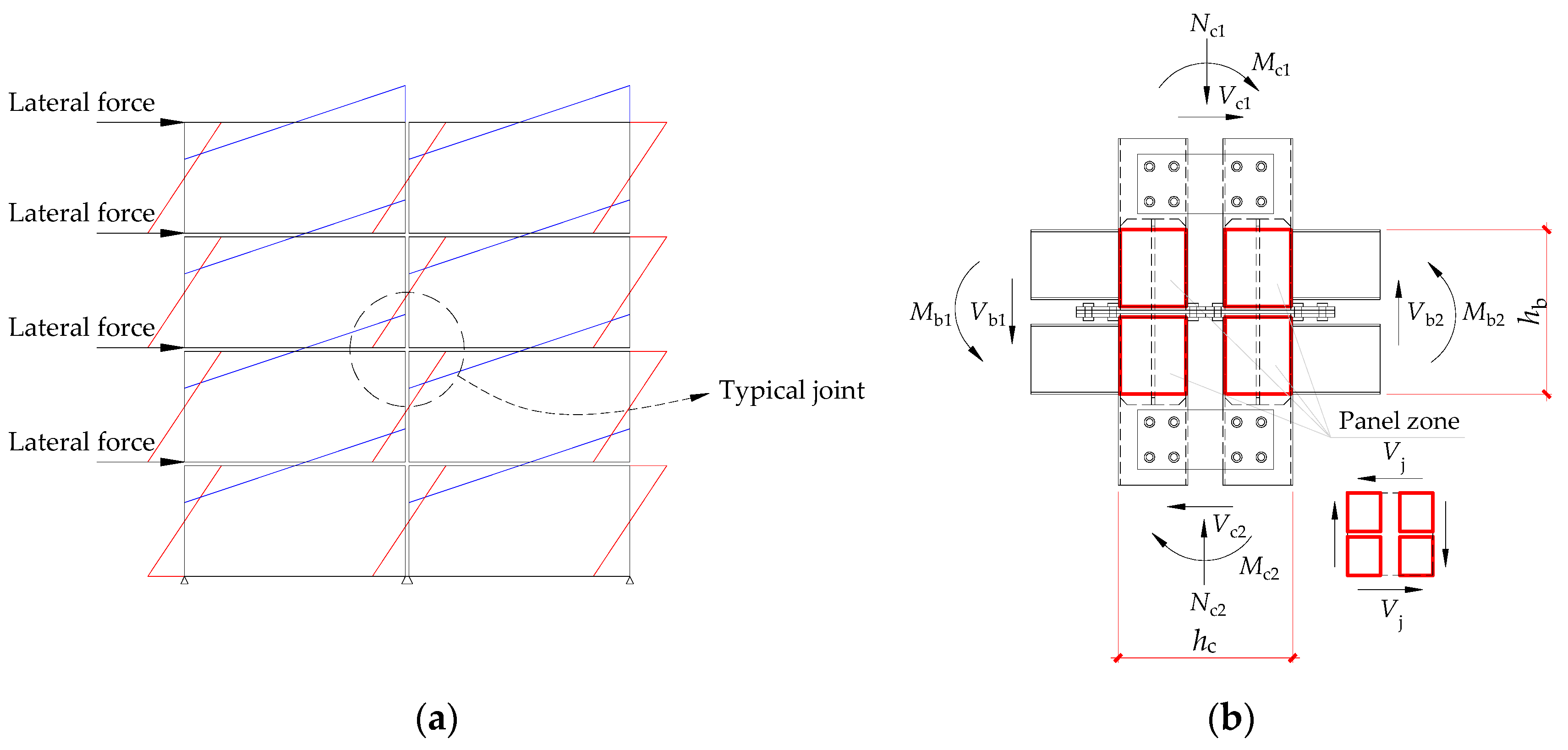
Under lateral force, such as seismic loads, the typical beam-to-column joint of multi-story steel frame structure bears axial force, bending moment, and shear force concomitantly. The inflection points of the columns and beams occur at the mid-span of the member length.
Figure 4 shows the bending moment distribution of the MSB frame and the internal forces around the panel zone of the proposed IMC. The core area of the connection bears bending moment
,
and shear force
,
from the beam end, and bending moment
,
; shear force
,
; and axial force
,
from the column end.
is the shear force of the panel zone.
and
are, respectively, the distance from the upper flange of the floor beam to the lower flange of the ceiling beam and the distance from the left flange of the left column to the right flange of the right column.
can be calculated by Equation (1).
3.2. Flexural Bearing Capacity
The flexural bearing capacity of the beam-to-column joint is reflected in the beam-to-column connection, and it is also reflected in the beam’s flexural bearing capacity under the principle of “the connection is stronger than the member”. For the proposed IMC, assuming that the floor beam and ceiling beam bend around their respective neutral axis without combination, the flexural bearing capacity of the IMC is the sum of the two beams, calculated by Equation (2).
where
,
are, respectively, the flexural bearing capacity of the floor beam and ceiling beam, calculated by Equation (3).
where
,
are the section modulus of the beam and the plastic adoptive factor of the section, respectively, calculated according to the Chinese code for the design of steel structures (GB50017-2017) [
20].
is the yield strength of steel.
3.3. Shear Capacity of the Panel Zone
When the beam and column are rigidly connected, the column web has the possibility of yielding or local buckling under the action of the bending moment and shear force around the panel zone. Therefore, the shear strength and stability of the panel zone should be checked. GB50017-2017 introduced the normalized width–thickness ratio of the panel zone, ignoring the shear force and axial force from the column end, and the shear capacity of the panel zone is checked by Equation (4).
where
,
are, respectively, the bending moment design values of beam ends on both sides of the panel zone.
is the volume of the panel zone.
is the shear strength of the panel zone, calculated according to the normalized width–thickness ratio
.
varies between
and
, corresponding to
varying between 0.6 and 1.2 (
is the design value of the shear strength of steel).
It is difficult to determine
and
of the proposed IMC due to the fact that the configuration is different from the conventional steel frame beam-to-column joint, and there is no corresponding design formula in the code. Cai [
21] expounded the concept of the shape coefficient of the panel zone and proposed several calculation methods for the volume of several irregular panel zones. For box section columns and tubular section columns, the shape coefficient of 1.8 and π/2, respectively, are also presented in GB50017-2017. Based on the concept of the shape coefficient, a panel zone volume modified factor
is proposed in this study for the proposed IMC, calculated by Equation (5).
where
is the effective shear resisting volume, which is calculated by Equation (6) when simulating the critical state of yielding of the panel zone by using the numerical analysis method.
is the volume of the panel zone specified in GB50017-2017, which is calculated according to the formula for box section columns. Since the proposed IMC contains eight columns, it is eight times the volume of a single column.
where
,
are, respectively, the bending moment values of the beam ends on both sides at the yielding critical state of the panel zone.
is the yield shear strength of steel.
3.4. Initial Rotational Stiffness
The proposed IMC is in an elastic stage when it is initially stressed, and the connection deformation can be decomposed into two parts by applying the superposition principle. The first part is the deformation caused by the beam and column bending, assuming that the beam and column are rigidly connected, as shown in
Figure 5a. Since the shear deformation of the beam and column is very small and can be ignored, the expression of the first part of the deformation, i.e., Equation (8), can be derived by Equation (7) using the unit–load method in structural mechanics.
where
,
are the bending moment of the structure under the unit load and under the external load, respectively.
,
are, respectively, Young’s modulus and the bending moments of inertia of the beam or column member.
is the rotation corresponding to the first part of the deformation;
is the lateral force;
,
are, respectively, the length of the beam and the column;
,
are, respectively, Young’s modulus of the floor beam and the ceiling beam; and
,
are, respectively, the bending moments of inertia of the floor beam and the ceiling beam.
The second part is the deformation caused by the panel zone shearing, as shown in
Figure 5b. Based on the assumption of the pure shearing mechanism of the panel zone [
22], the shear stiffness
, i.e., Equation (9), can be used to calculate the expression of the second part of the deformation, i.e., Equation (11).
where
is the shear modulus of the column web, calculated by Equation (10).
is the thickness of the column web.
where
is Young’s modulus of steel, and
is Poisson’s ratio of steel.
where
is the rotation corresponding to the second part of the deformation.
After calculating
and
, the initial rotational stiffness
of the proposed IMC can be calculated by Equation (12).
However, since Equation (9) is based on the pure shearing mechanism, ignoring the bending deformation of the panel zone, and is derived for beam-to-column using H-shaped steel, the calculation accuracy is not satisfied. In addition, the proposed IMC in this study exhibits some semi-rigid characteristics due to the special configuration, which also affects the initial rotational stiffness. Due to the above factors, an initial rotational stiffness modified factor
is proposed in this study, calculated by Equation (13).
where
is the initial rotational stiffness of the proposed IMC obtained by numerical simulation.
4. Numerical Analysis
4.1. Finite Element Model Information
To study the mechanical performance of the proposed IMC and calculate the panel zone volume modified factor
and the initial rotational stiffness modified factor
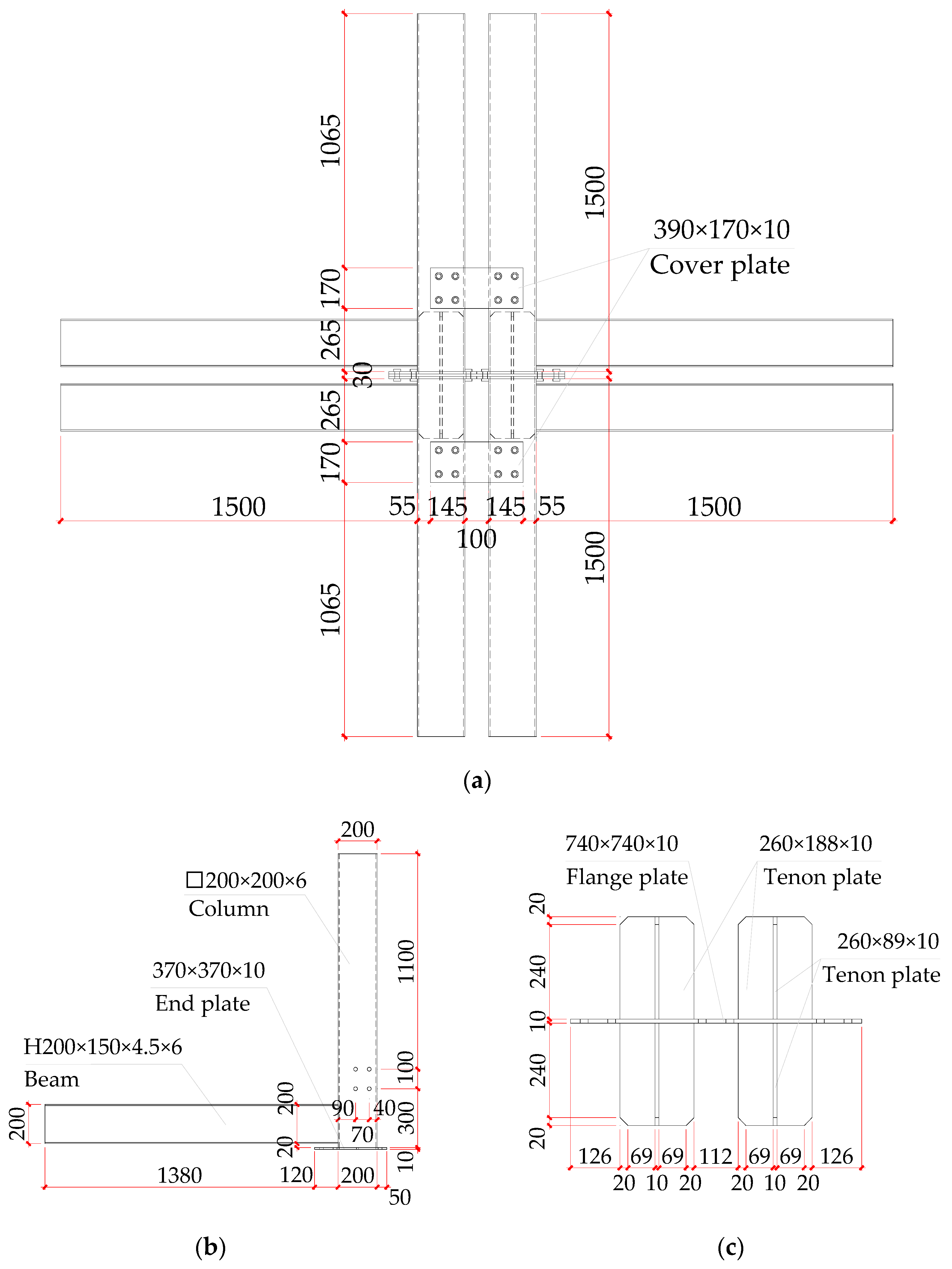
, a numerical simulation study was conducted using the general finite element analysis software ANSYS 2022 R2. A four-story MSB office is used as the structural prototype for design verification, and the most stressed IMC is extracted as the standard model. The column section is □200 × 200 × 6 (box section), and the beam section is H200 × 150 × 4.5 × 6. The length of the beam and column are, respectively, 1.5 m and 1.28 m, and the thickness of the end plate, cover plate, flange plate of the connector, and tenon plate of the connector is 10 mm. The bolts and one-side bolts are Grade 10.9 M20 high-strength bolts with standard round holes. The specific dimensions of the standard model are shown in
Figure 6. To analyze the factors affecting the mechanical performance and the two proposed factors mentioned above, another eight models with different parameters were established, involving axial compression ratios, the thickness of the tenon plate, the column section, and the beam section. The specific parameters of the models are shown in
Table 1. The models are numbered in the form of “C-a-b(t)-c-d”, where a represents the thickness of the column web, b represents the thickness of the beam web, t represents the beam section type, c represents the thickness of the tenon plate, and d represents the axial compression ratio. For example, C-6-4.5(H)-10-0.2 represents the standard model.
The strength grade of steel is Q355B, and the material density is 7850 kg/m
3. The Young’s modulus
and Poisson’s ratio
of steel are, respectively, 2.06 × 10
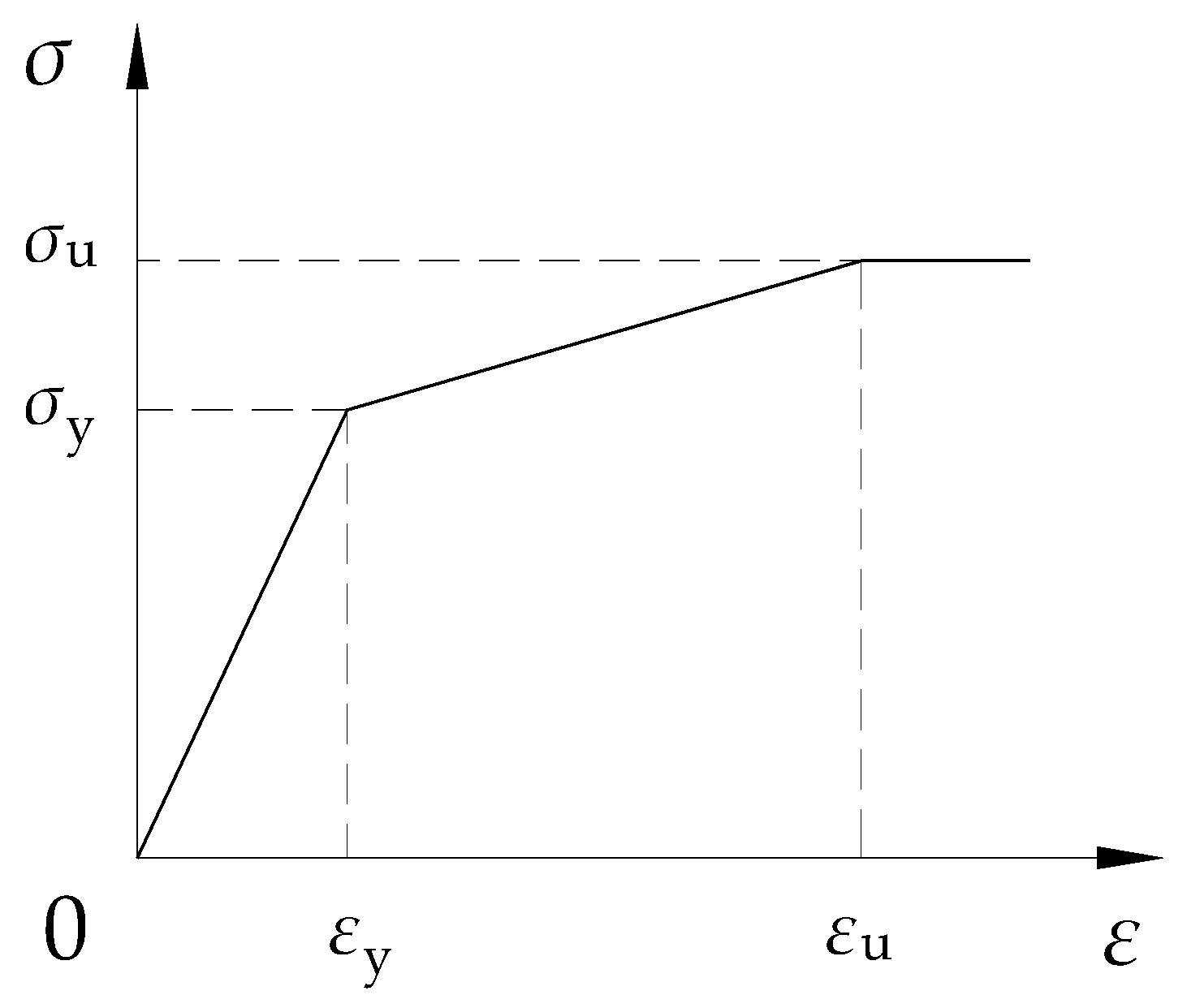
5 MPa and 0.3. The trilinear kinematic hardening constitutive model is adopted for both high-strength bolts and other members, as shown in
Figure 7. The yield stress
, yield strain
, ultimate stress
, and ultimate strain
refer to the experimental data of reference [
23], and the values are shown in
Table 2.
To obtain good solution accuracy, all parts of the finite element model use the solid element “Solid186” with mesh refinement near the panel zone. The beam, column, and end plate of a single module are combined into a whole, in the way of node-sharing topology, and all the remaining contacts are frictional contacts with a friction coefficient of 0.3 [
18,
19]. The boundary conditions are set in accordance with the constrained state of the connection in the structure, with hinged support at the bottom of columns and sliding hinged support at the end of beams, and all out-of-plane displacements are constrained. The column top loading method in the Chinese specification for the seismic test of buildings (JGJ/T 101-2015) [
24] is adopted to better consider the P-Delta effect in the actual structure. The loading step is divided into three steps: the first step is to apply the bolt preload of 155 kN for each bolt; the second step is to apply a constant axial force on the top of columns; the third step is to apply a horizontal displacement at the top of columns, monotonically loaded to 150 mm. To ensure the convergence of the calculation results, automatic time sub-steps are set for each load step, with an initial 30 steps, a minimum of 10 steps, and a maximum of 100 steps. The finite element model is shown in
Figure 8.
4.2. Finite Element Model Validation
To verify the validity of the finite element model, a comparative analysis between the finite element model and the test specimen was conducted. The specimen selected for analysis is MJ5 in the research of the IMC proposed by Cao et al. [
25]. The specimen MJ5 is a cross-shaped bolted-cover plate IMC, and its size and material properties are similar to those of the IMC proposed in this study. The loading method and protocol are the same as those in this study. The comparative analysis between the experimental test and the numerical simulation can preferably reflect the validity of the finite element model.
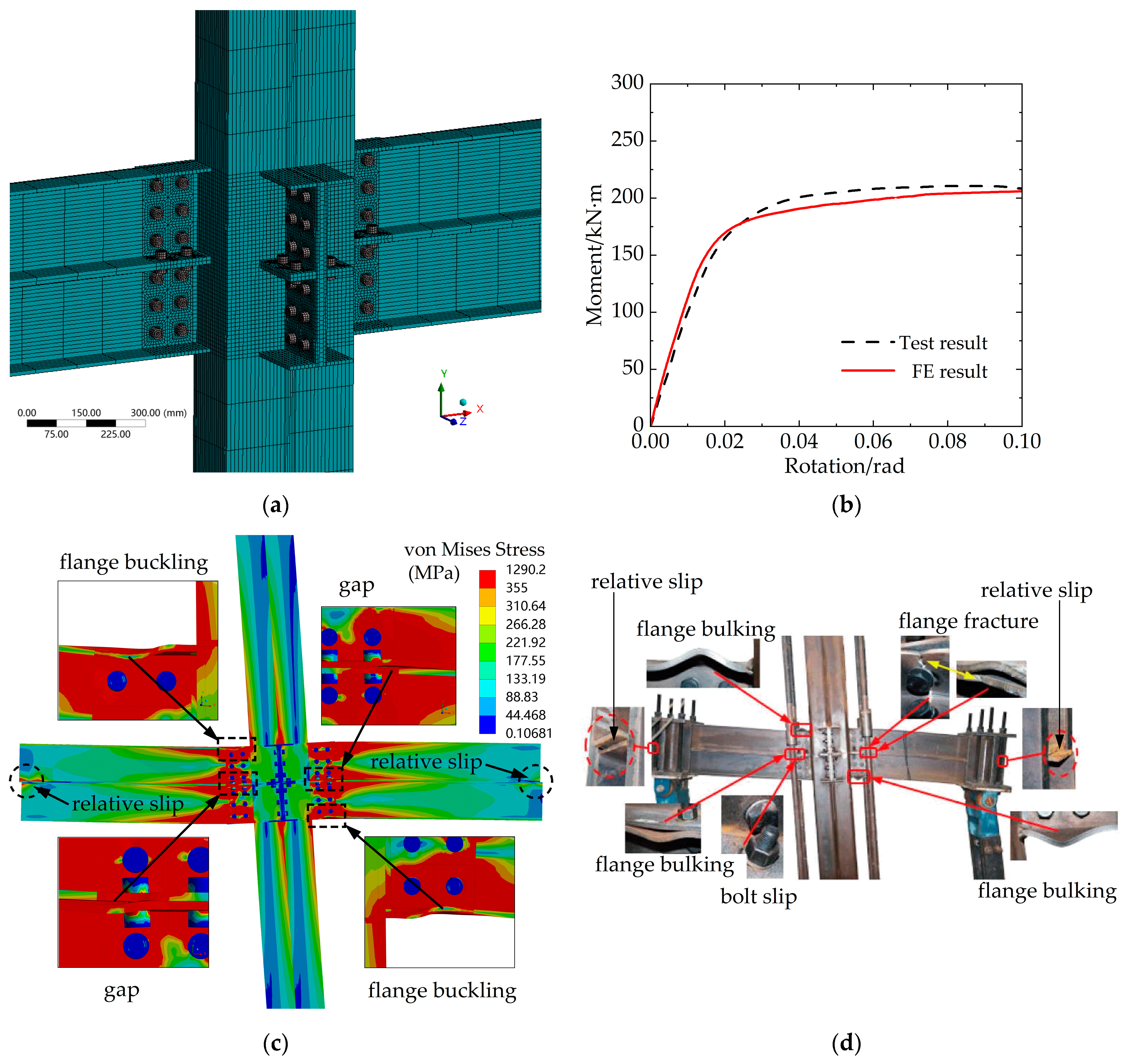
The finite element model of specimen MJ5 was established using the same modeling method, contact settings, boundary conditions, mesh size, and division method in 4.1, as shown in
Figure 9a. In the preliminary analysis, the appropriate mesh size was determined as 10 mm of the core area and 100 mm of the non-core area with the face mapping method for bolts and the multizone method for the whole model to ensure the accuracy of the calculation results. The moment–rotation curves of specimen MJ5 were compared with the result from the finite element analysis, as shown in
Figure 9b. It was observed that the ultimate capacity, stiffness, and ductility of the test specimen were well predicted by the finite element model. The maximum error of the bearing capacity is only 6%. Some minor fluctuations and inconstancies in the stiffness or capacity between the test and the numerical result were observed, which might be due to simplifications during the finite element analysis, such as a hexagonal head of bolts and nuts were modeled together as circular, while threads on nuts and the bolts shank were not modeled, and the space between the bolt and the hole was not considered. The failure patterns of the specimen in the finite element result and test result are shown in
Figure 9c,d. The main failure patterns observed in the test were beam flange bulking and fracture, gap generation between upper and lower beams, and bolt slip and relative slip generation in the ends of upper and lower beams. The failure pattens showed by the finite element model were following the test result basically. In summary, the finite element model of the IMC proposed in this study is validated and can be used to further analyze its mechanical performance.
4.3. Finite Element Analysis Results
4.3.1. Load–Displacement Curves
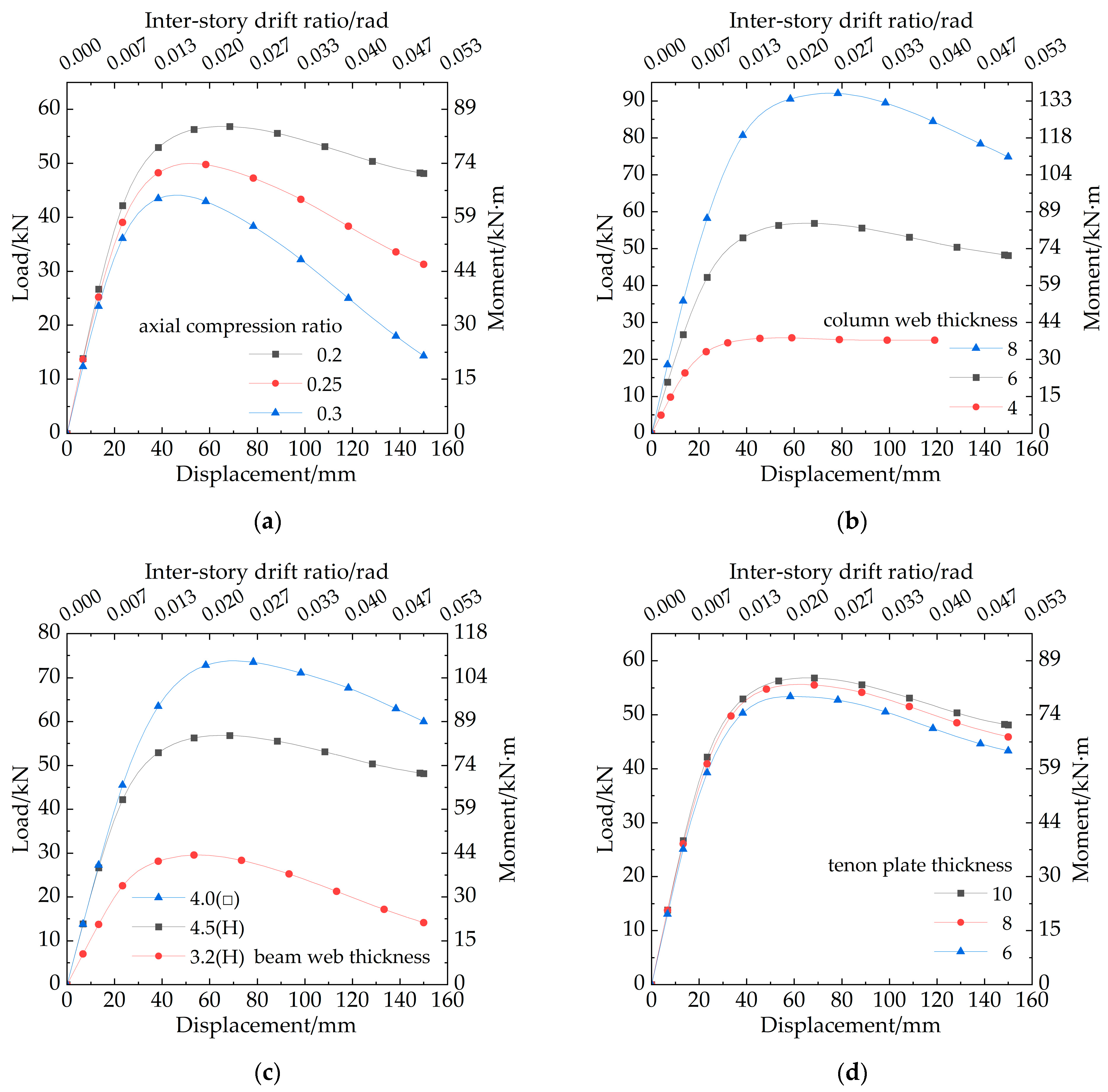
The load–displacement curves of each model and the corresponding bending moment–inter-story drift ratio curves are shown in
Figure 10, where the bending moment is the product of the load and the length of the upper columns, and the inter-story drift ratio is the ratio of the horizontal displacement to the total length of the columns.
Figure 10a–d represent the curves of the models corresponding to different axial compression ratios, thicknesses of the column web, thicknesses of the beam web, and thicknesses of the tenon plate, respectively, where the black lines with block legends in all figures indicate the results of the standard model. It is worth mentioning that the overall instability occurred in model C-4-4.5(H)-10-0.2 when loading to 119 mm drift, and the load could not be further applied because the thickness of the column web is too thin, while other models can be loaded to 150 mm. Using the equivalent elastoplastic energy method, the yield load
; peak load
; ultimate load
(where
); corresponding displacements
,
,
; and ductility factor
of each model can be calculated from the curves, as shown in
Table 3. According to the curves, the greatest effect on the bearing capacity of the proposed IMC is the thickness of the column web, which decreases from 8 to 6 to 4, with the peak loads decreasing by 38.3% and 72.0%, respectively; the second major effect is the thickness of the beam web, which decreases from 4.0(□) to 4.5(H) to 3.2(H), with the peak loads decreasing by 22.7% and 59.8%, respectively; the third major effect is the axial compression ratio, which rises from 0.2 to 0.25 to 0.3, with the peak loads decreasing by 12.4% and 23.4%, respectively; and the minimum effect is the thickness of the tenon plate, which decreases from 10 to 8 to 6, with the peak loads decreasing by 2.3% and 6.0%, respectively.
The column top loading method causes a significant P-Delta effect. In the study of simplified structural behaviors of IMCs proposed by Lacey et al. [
26,
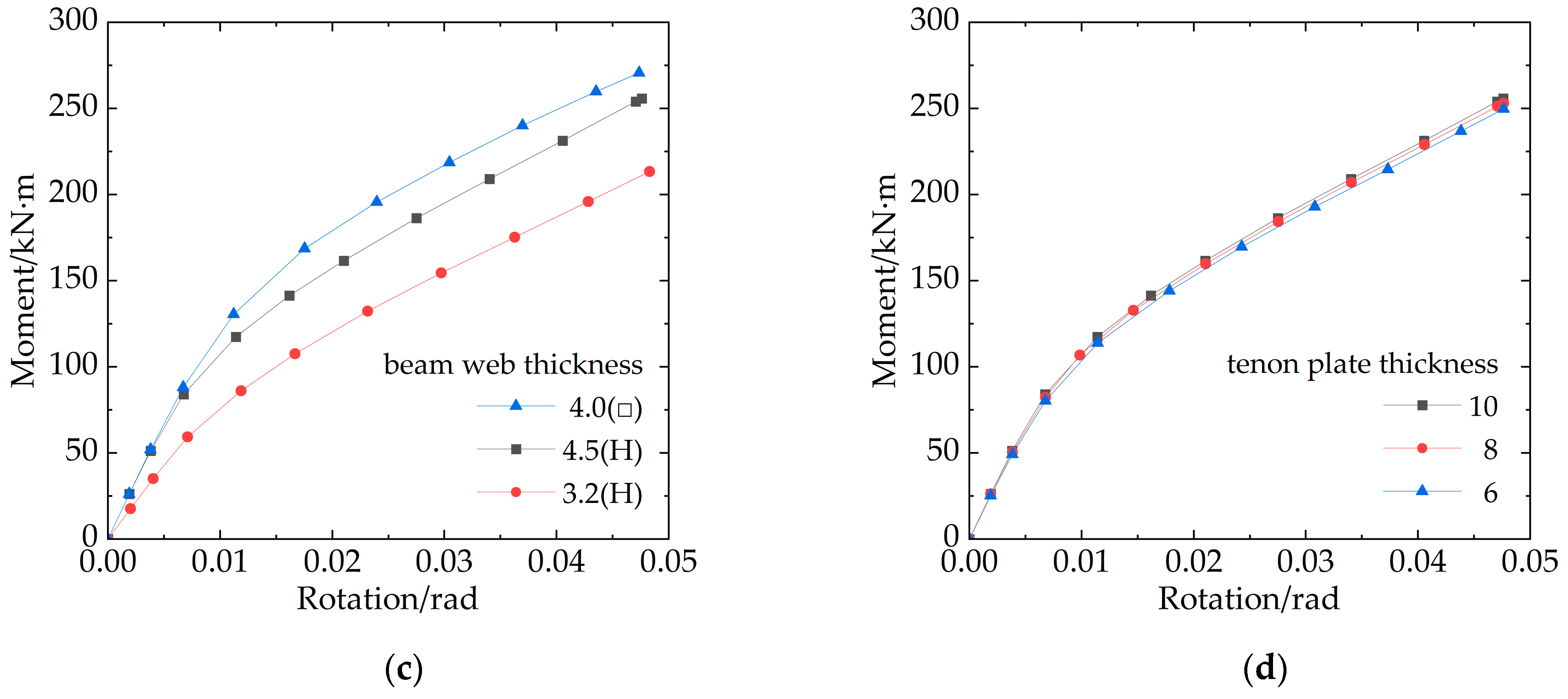
27], the combined effect of the bending moment and axial force at the column top was considered, i.e., the P-Delta effect was considered. For the proposed IMC in this study, the second-order bending moment generated by the axial force cannot be ignored, and the relationship between the actual bending moment and the rotation of the column end output by numerical simulation is analyzed for stiffness.
Figure 11 shows the moment–rotation curves of the column end considering the P-Delta effect of each model, where (a)–(d) represent the curves of the models corresponding to different axial compression ratios, thicknesses of the column web, thicknesses of the beam web, and thicknesses of the tenon plate, respectively. The initial rotational stiffness of each model calculated by the curves will be used for the initial rotational stiffness modification below.
4.3.2. Stress Analysis
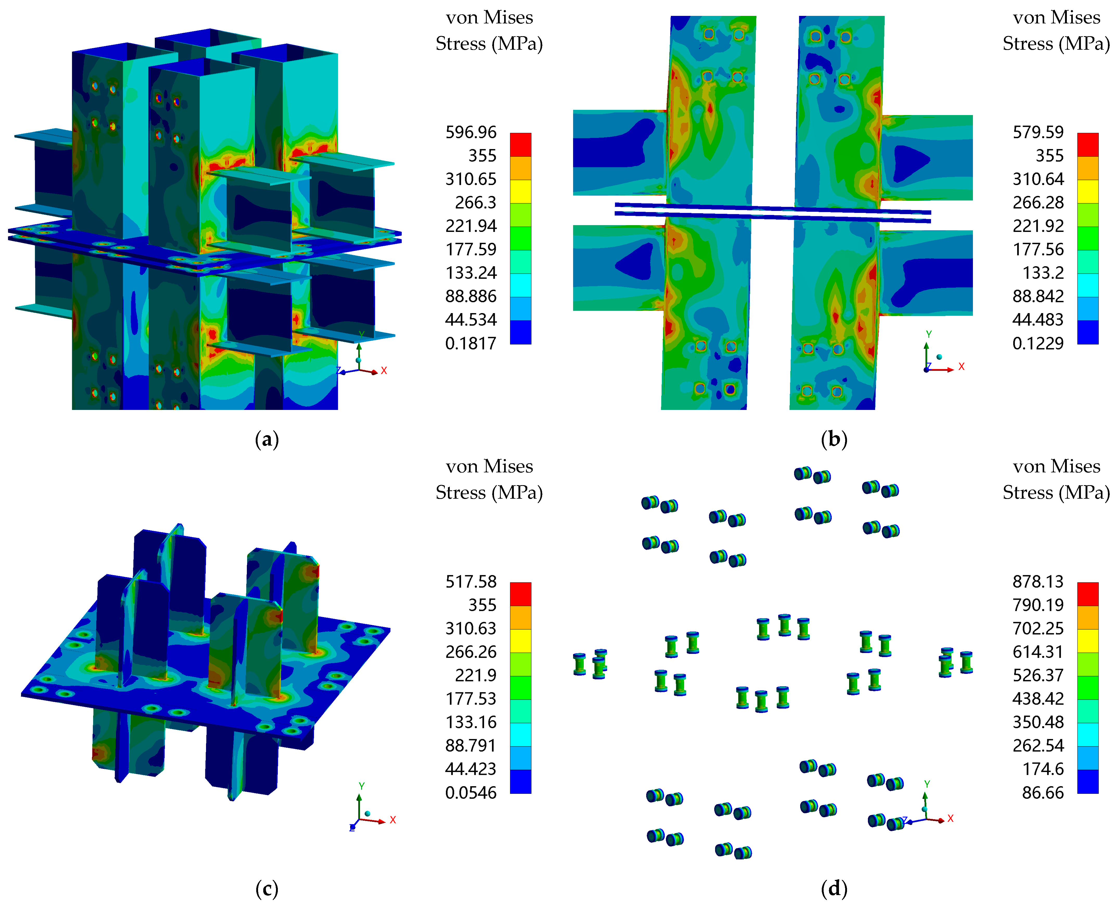
The von Mises yield condition is used as the material yield criterion for the steel structure failure criterion, and the flow rule and kinematic hardening criterion are used after the material yields. The stress development process is similar for all models, and the standard model C-6-4.5(H)-10-0.2 is used as an example for stress analysis. When the horizontal displacement is loaded to 35 mm, the stress concentration occurs at the column flange near the beam flange, where the stress first reached the yield stress, as shown in
Figure 12a, and the corresponding load is 50.56 kN. When the horizontal displacement is loaded to 80 mm, the surface of the panel zone reached the yield stress, as shown in
Figure 12b, and the corresponding load is 56.11 kN. When the horizontal displacement is loaded to 130 mm, the tenon of the cross-shaped plug-in connector reached the yield stress, as shown in
Figure 12c, and the corresponding load is 50.23 kN. The stress distribution of the high-strength bolts when loaded to a maximum displacement of 150 mm is shown in
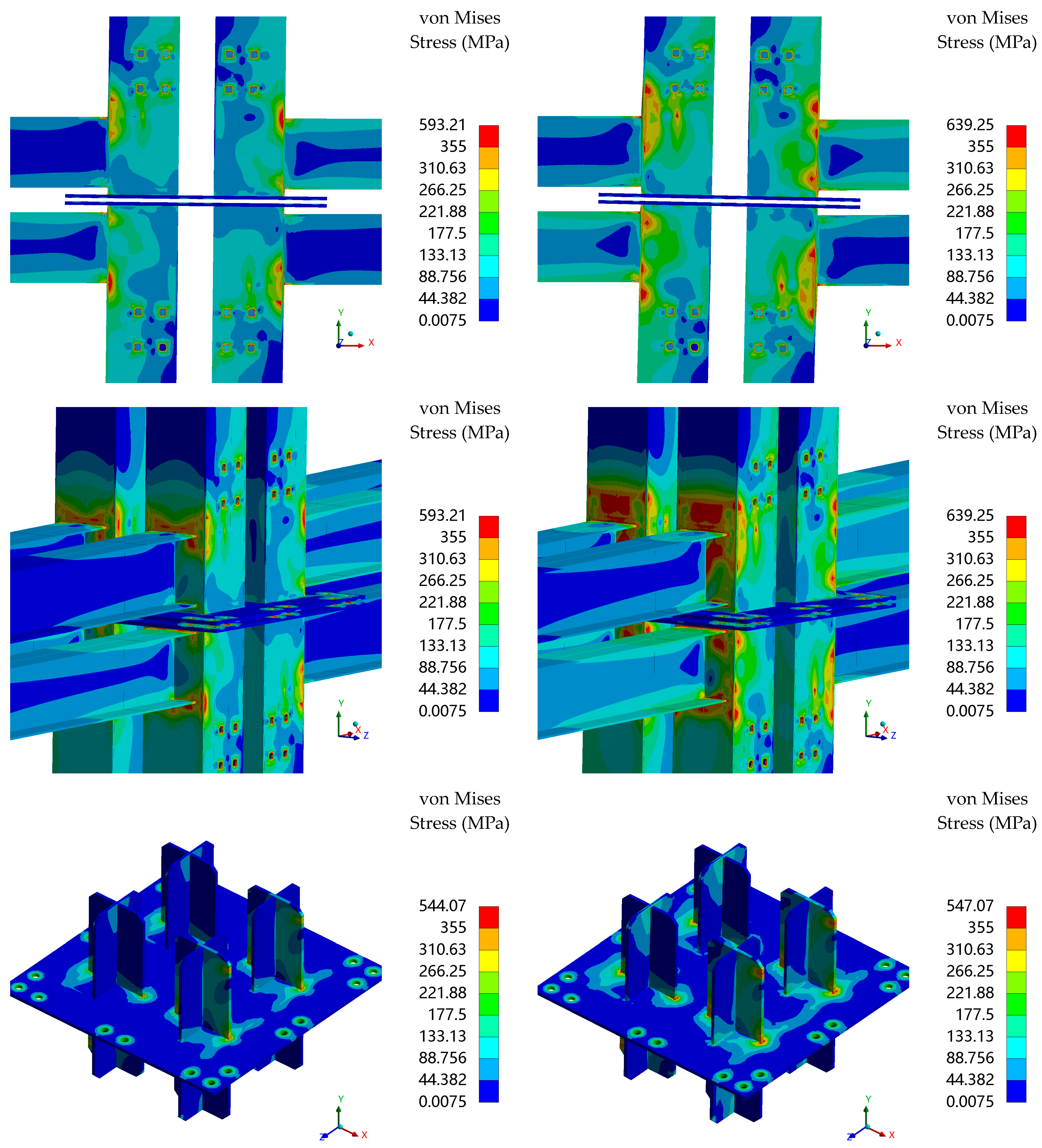
Figure 12d, and all bolts did not reach the yield stress, indicating that the high-strength bolts remained elastic throughout the loading process. It can be seen from the stress diagram that during the entire loading process, the damage development process of the proposed IMC can be approximately divided into three stages: (1) The stress at the beam-to-column connection increases rapidly, and the column flange near the connection yields earlier than the beam. (2) The plate of the panel zone begins to yield, and the stress increases rapidly at the four corners. (3) The stress at the end of the tenon in extruded contact with the column and at the connection of the tenon plate and the flange plate of the cross-shaped plug-in connector reach the yield stress. The stress distribution of the whole model, the front of the panel zone, the side of the panel zone, and the cross-shaped plug-in connector corresponding to the yield load and peak load of the load–displacement curve is shown in
Figure 13.
4.3.3. Calculation of the Panel Zone Volume Modified Factor
The bending moment values of the beam ends on both sides at the yielding critical state of the panel zone can be output by numerical simulation, and the values of
can be calculated by Equations (5) and (6), as shown in
Table 4. According to the results of
, the greatest effect is the thickness of the beam web, varying between 3.2(H) and 4.0(□), which is positively correlated with
varying between 0.25 and 0.41; the second major effect is the thickness of the column web, varying between 4 and 8, which is positively correlated with
varying between 0.28 and 0.40; the minimum effect is the thickness of the tenon plate, varying between 6 and 10, which is positively correlated with
varying between 0.33 and 0.35; the effect of the axial compression ratio can be ignored, and
is 0.35.
4.3.4. Calculation of the Initial Rotational Stiffness Modified Factor
The initial rotational stiffness
can be calculated from the moment–rotation curves in
Figure 11, and the
values can be calculated by Equations (12) and (13), as shown in
Table 5. According to the results of
, the greatest effect is the thickness of the column web, varying between 4 and 8, which is positively correlated with
varying between 0.41 and 0.67; the second major effect is the thickness of the beam web, and due to the particularity of the box section beam, only the web thickness of the H-section beam is negatively correlated with
, and it can be concluded that the direct factor affecting
is the bending moments of inertia of the beam, that is, the bending moment of inertia
is negatively correlated with
,where
varies between 2091.84 cm
4 and 3886.68 cm
4, and
varies between 0.57 and 0.55; the effect of the thickness of the tenon plate is approximately the same as that of the thickness of the column web, where the thickness of the tenon varies between 6 and 10, which is positively correlated with
varying between 0.51 and 0.55; the effect of the axial compression ratio can be ignored, and
is 0.55.
4.3.5. Evaluation of Rotational Stiffness
According to the classification of steel connections in EuroCode3 [
28], connections are divided into three types: rigid, semi-rigid, and hinged. For a non-sway frame, when the ratio of the connection stiffness to the beam bending stiffness is less than 0.5, between 0.5 and 8.0, and greater than 8.0, the connection is considered to be hinged, semi-rigid, and rigid, respectively. The stiffness ratios of the nine models are calculated in
Table 6.
and
are, respectively, Young’s modulus and the bending moments of inertia of the beam;
is the length of the beam span; and
is the initial rotational stiffness of the models. It can be seen that the stiffness ratios of the nine models are between 1.81 and 3.34. In fact, the initial rotational stiffness defined in this study considered the bending deformation of the beam and column to better reflect the inter-story drift ratio of the structure. After deducting the contribution of the bending deformation of the beam and column, the initial rotational stiffness
become larger than
, and the stiffness ratios are greater than 8.0, except model C-4-4.5(H)-10-0.2 with a weak column section. In summary, the proposed IMC is considered to be a rigid connection or inclined to rigid connection, which also means a higher bearing capacity under the same displacement constraints. Compared with IMC simplified as a hinged connection in some research, the mechanical performance of the proposed IMC in this study is better.
5. Design Recommendations
Through theoretical research and numerical simulation, the recommended design method is presented for the proposed IMC in this study, which can be divided into the following four parts.
5.1. Calculation of Flexural Bearing Capacity
The flexural bearing capacity of the proposed IMC can be calculated according to Equation (3). The proposed IMC mainly use cold-formed thin-walled steel with a relatively large width–thickness ratio of the plate, and the plastic adoptive factor is taken as 1.0. Therefore, the ultimate flexural bearing capacity is exactly the yield flexural bearing capacity .The results of numerical simulation show that the yield stress is first reached at the beam-to-column connection, and the bending moment at the end of the beam has not yet reached due to the particularity of the configuration, while the column flange reaches the yield stress one step ahead of the beam flange after that. To control the failure of the column, the bending moment of the beam end when the yield stress is reached at the beam-to-column connection is taken as the design limit, which is , calculated by numerical simulation results.
5.2. Calculation of Shear Capacity of the Panel Zone
The shear capacity of the panel zone of the proposed IMC can be calculated according to Equation (4), where
, and
is calculated by Equation (14) by the multiple linear regression method.
where
is the thickness of the column web;
is the bending moments of inertia of the beam;
is the thickness of the tenon plate; and
,
, and
are 1 mm, 1 cm
4, and 1 mm, respectively.
5.3. Calculation of Initial Rotational Stiffness
The initial rotational stiffness of the proposed IMC can be calculated according to Equation (12). Then,
is multiplied by the modified factor
, which is calculated by Equation (15) by the multiple linear regression method.
where
is the thickness of the column web;
is the bending moments of inertia of the beam;
is the thickness of the tenon plate; and
,
, and
are 1 mm, 1 cm
4, and 1 mm, respectively.
5.4. Calculation of High-Strength Bolts
The high-strength bolts connecting the upper and lower column end plates with the flange plate of the cross-shaped plug-in connector are subjected to axial force, bending moment, and shear force concomitantly, which can be calculated according to Equations (16) and (17),
where
and
are the axial force and bending moment of the bolt group, respectively. n is the number of bolts.
is the distance from each bolt to the centroid of the bolt group, and
is the maximum value in
.
is the preload of the high-strength bolt.
,
are the shear force and tensile force of a bolt, respectively, and
,
are the design values of the shear and tensile bearing capacity of a bolt, respectively.
6. Conclusions
This study proposed an innovative IMC with a cross-shaped plug-in connector. The mechanical model of the proposed IMC and the design formular of the flexural bearing capacity, shear capacity of the panel zone, and initial rotation stiffness were presented, and two modified factors are proposed to modify the shear resisting volume of the panel zone and the initial rotation stiffness. Considering the influences of axial compression ratios, sections of beams and columns, and the thickness of the tenon plate of the connector, nine finite element models were established. The mechanical performance of the proposed IMC was analyzed by numerical simulation, and the values of the two factors under different parameters were calculated. Finally, combined with the results of theoretical research and numerical simulation, the design recommendations were presented. Based on the existing research work, the following conclusions are drawn:
(1) For the bearing capacity of the proposed IMC, the column section has the greatest effect, followed by the beam section, then the axial compression ratio, and the thickness of the tenon plate has little effect. Due to the P-Delta effect, the bearing capacity of all models has a significant downward trend in the later period.
(2) The yielding mechanism and failure mode of the proposed IMC are as follows: the column web at the beam-to-column connection is damaged first, followed by the panel zone damage, and finally, the cross-shaped plug-in connector damage, which is attributed to the thin-walled structure of the component. Therefore, it is suggested that the bending moment limit of the beam end should be 0.6 times the resistance bending moment when the corresponding column web begins to fail.
(3) For the shear capacity of the panel zone, the sections of beams and columns have a large effect. The cross-shaped plug-in connector has a great contribution to the shear bearing capacity, but the thickness of the tenon plate has little effect, while the axial compression ratio has almost no effect. Proposed formulas provide the recommended calculation method for the shear capacity of the panel zone.
(4) For the initial rotational stiffness, the column section has a greater effect, followed by the beam section and the thickness of the tenon plate, while the axial compression ratio has almost no effect. Proposed formulas provide the recommended calculation method for the initial rotational stiffness. In addition, the proposed IMC is considered to be a rigid connection or inclined to rigid connection.
Author Contributions
Conceptualization, H.M., Z.H, X.S. and Y.L.; formal analysis, Z.H.; writing—original draft preparation, Z.H.; writing—review and editing, H.M.; project administration, H.M. and X.S.; supervision, Y.L. All authors have read and agreed to the published version of the manuscript.
Funding
This research received no external funding.
Data Availability Statement
Not applicable.
Conflicts of Interest
The authors declare no conflict of interest.
References
- Lacey, A.W.; Chen, W.; Hao, H.; Bi, K. Structural Response of Modular Buildings—An Overview. J. Build. Eng. 2018, 16, 45–56. [Google Scholar] [CrossRef]
- Lacey, A.W.; Chen, W.; Hao, H.; Bi, K. Review of Bolted Inter-Module Connections in Modular Steel Buildings. J. Build. Eng. 2019, 23, 207–219. [Google Scholar] [CrossRef]
- Lacey, A.W.; Chen, W.; Hao, H. Experimental Methods for Inter-Module Joints in Modular Building Structures—A State-of-the-Art Review. J. Build. Eng. 2022, 46, 103792. [Google Scholar] [CrossRef]
- Chen, Z.; Khan, K.; Khan, A.; Javed, K.; Liu, J. Exploration of the Multidirectional Stability and Response of Prefabricated Volumetric Modular Steel Structures. J. Constr. Steel Res. 2021, 184, 106826. [Google Scholar] [CrossRef]
- Ferdous, W.; Bai, Y.; Ngo, T.D.; Manalo, A.; Mendis, P. New Advancements, Challenges and Opportunities of Multi-Storey Modular Buildings—A State-of-the-Art Review. Eng. Struct. 2019, 183, 883–893. [Google Scholar] [CrossRef]
- Deng, E.; Zong, L.; Ding, Y.; Zhang, Z.; Zhang, J.; Shi, F.; Cai, L.; Gao, S. Seismic Performance of Mid-to-High Rise Modular Steel Construction—A Critical Review. Thin-Walled Struct. 2020, 155, 106924. [Google Scholar] [CrossRef]
- Srisangeerthanan, S.; Hashemi, M.J.; Rajeev, P.; Gad, E.; Fernando, S. Review of Performance Requirements for Inter-Module Connections in Multi-Story Modular Buildings. J. Build. Eng. 2020, 28, 101087. [Google Scholar] [CrossRef]
- Thai, H.; Ngo, T.; Uy, B. A Review on Modular Construction for High-Rise Buildings. Structures 2020, 28, 1265–1290. [Google Scholar] [CrossRef]
- Nadeem, G.; Safiee, N.A.; Bakar, N.A.; Karim, I.A.; Nasir, N.A.M. Connection Design in Modular Steel Construction: A Review. Structures 2021, 33, 3239–3256. [Google Scholar] [CrossRef]
- Chen, Z.; Liu, J.; Yu, Y. Experimental Study on Interior Connections in Modular Steel Buildings. Eng. Struct. 2017, 147, 625–638. [Google Scholar] [CrossRef]
- Chen, Z.; Liu, J.; Yu, Y.; Zhou, C.; Yan, R. Experimental Study of an Innovative Modular Steel Building Connection. J. Constr. Steel Res. 2017, 139, 69–82. [Google Scholar] [CrossRef]
- Deng, E.; Zong, L.; Ding, Y.; Dai, X.; Lou, N.; Chen, Y. Monotonic and Cyclic Response of Bolted Connections with Welded Cover Plate for Modular Steel Construction. Eng. Struct. 2018, 167, 407–419. [Google Scholar] [CrossRef]
- Deng, E.; Zong, L.; Ding, Y.; Luo, Y. Seismic Behavior and Design of Cruciform Bolted Module-to-Module Connection with Various Reinforcing Details. Thin-Walled Struct. 2018, 133, 106–119. [Google Scholar] [CrossRef]
- Zhang, G.; Xu, L.; Li, Z. Development and Seismic Retrofit of an Innovative Modular Steel Structure Connection Using Symmetrical Self-Centering Haunch Braces. Eng. Struct. 2021, 229, 111671. [Google Scholar] [CrossRef]
- Lacey, A.W.; Chen, W.; Hao, H.; Bi, K. New Interlocking Inter-Module Connection for Modular Steel Buildings: Experimental and Numerical Studies. Eng. Struct. 2019, 198, 109465. [Google Scholar] [CrossRef]
- Sendanayake, S.V.; Thambiratnam, D.P.; Perera, N.; Chan, T.; Aghdamy, S. Seismic Mitigation of Steel Modular Building Structures through Innovative Inter-Modular Connections. Heliyon 2019, 5, e02751. [Google Scholar] [CrossRef] [PubMed]
- Sendanayake, S.V.; Thambiratnam, D.P.; Perera, N.J.; Chan, T.H.T.; Aghdamy, S. Enhancing the Lateral Performance of Modular Buildings through Innovative Inter-Modular Connections. Structures 2021, 29, 167–184. [Google Scholar] [CrossRef]
- Khan, K.; Yan, J. Finite Element Analysis on Seismic Behaviour of Novel Joint in Prefabricated Modular Steel Building. Int. J. Steel Struct. 2020, 20, 752–765. [Google Scholar] [CrossRef]
- Khan, K.; Yan, J. Numerical Studies on the Seismic Behaviour of a Prefabricated Multi-Storey Modular Steel Building with New-Type Bolted Joints. Adv. Steel Constr. 2021, 17, 1–9. [Google Scholar] [CrossRef]
- GB50017-2017; Standard for Design of Steel Structures. China Planning Press: Beijing, China, 2017.
- Cai, Y. On the calculation of the panel zone of steel frames. In Proceedings of the Celebrating the 60th Anniversary of Professor Liu Xiliang’s Teaching and the 11th National Symposium on Modern Structural Engineering; Tianjin University: Tianjin, China, 2011; pp. 172–177. (In Chinese). [Google Scholar]
- Pan, L.; Chen, Y. Modified formula for calculating elastic stiffness of panel zone in H-shaped beam-column connections. Eng. Mech. 2016, 33, 68–74. (In Chinese) [Google Scholar]
- Wang, X. Study on Seismic Behavior of Fabricated Beam-to-Column High-Strength Bolted Joint with External Diaphragms. Ph.D. Thesis, Qingdao University of Technology, Qingdao, China, 2020. (In Chinese). [Google Scholar]
- JGJ/T 101-2015; Specification for Seismic Test of Buildings. China Ministry of Construction: Beijing, China, 2015.
- Cao, K.; Zhai, S.; Wang, W. Experimental study on mechanical performance of bolted-cover plate inter-module connections. J. Build. Struct. 2023, 44, 81–93. (In Chinese) [Google Scholar] [CrossRef]
- Lacey, A.W.; Chen, W.; Hao, H.; Bi, K. Simplified Structural Behaviours of Post-Tensioned Inter-Module Connection for Modular Buildings. J. Constr. Steel Res. 2020, 175, 106347. [Google Scholar] [CrossRef]
- Lacey, A.W.; Chen, W.; Hao, H.; Bi, K. New Interlocking Inter-Module Connection for Modular Steel Buildings: Simplified Structural Behaviours. Eng. Struct. 2021, 227, 111409. [Google Scholar] [CrossRef]
- EN 1993-1-8: 2005 CEN; Eurocode 3: Design of Steel Structures-Part 1-8: Design of Joints. European Committee for Standardization: Brussels, Belgium, 2005.
Figure 1.
Composition of modular buildings: (a) Module assembly; (b) Module composition.
Figure 1.
Composition of modular buildings: (a) Module assembly; (b) Module composition.
Figure 2.
Details of the proposed IMC and its assembling process.
Figure 2.
Details of the proposed IMC and its assembling process.
Figure 3.
Configuration comparison: (
a) IMC proposed by Chen et al. [
10,
11]; (
b) IMC proposed by Deng et al. [
12,
13].
Figure 3.
Configuration comparison: (
a) IMC proposed by Chen et al. [
10,
11]; (
b) IMC proposed by Deng et al. [
12,
13].
Figure 4.
Mechanical model: (a) Bending moment distribution of the MSB frame; (b) Internal forces around the panel zone of the proposed IMC.
Figure 4.
Mechanical model: (a) Bending moment distribution of the MSB frame; (b) Internal forces around the panel zone of the proposed IMC.
Figure 5.
Deformation of the proposed IMC: (a) Bending deformation of the beam and column; (b) Shearing deformation of the panel zone.
Figure 5.
Deformation of the proposed IMC: (a) Bending deformation of the beam and column; (b) Shearing deformation of the panel zone.
Figure 6.
Specific dimensions of the standard model: (a) Overall dimensions; (b) Single-module dimensions; (c) Connector dimensions.
Figure 6.
Specific dimensions of the standard model: (a) Overall dimensions; (b) Single-module dimensions; (c) Connector dimensions.
Figure 7.
The trilinear kinematic hardening constitutive model.
Figure 7.
The trilinear kinematic hardening constitutive model.
Figure 8.
Details of the finite element model.
Figure 8.
Details of the finite element model.
Figure 9.
Validation of finite element model: (
a) Finite element model of specimen MJ5; (
b) Moment–rotation curves of test compared with finite element analysis result; (
c) Failure pattens showed by finite element model; (
d) Failure pattens showed by test [
25].
Figure 9.
Validation of finite element model: (
a) Finite element model of specimen MJ5; (
b) Moment–rotation curves of test compared with finite element analysis result; (
c) Failure pattens showed by finite element model; (
d) Failure pattens showed by test [
25].
Figure 10.
Load–displacement curves: (a) Different axial compression ratios; (b) Different thicknesses of the column web; (c) Different thicknesses of the beam web; (d) Different thicknesses of the tenon plate.
Figure 10.
Load–displacement curves: (a) Different axial compression ratios; (b) Different thicknesses of the column web; (c) Different thicknesses of the beam web; (d) Different thicknesses of the tenon plate.
Figure 11.
Moment–rotation curves: (a) Different axial compression ratios; (b) Different thicknesses of the column web; (c) Different thicknesses of the beam web; (d) Different thicknesses of the tenon plate.
Figure 11.
Moment–rotation curves: (a) Different axial compression ratios; (b) Different thicknesses of the column web; (c) Different thicknesses of the beam web; (d) Different thicknesses of the tenon plate.
Figure 12.
Stress development process: (a–d) As described in the text above.
Figure 12.
Stress development process: (a–d) As described in the text above.
Figure 13.
Stress distribution of the whole model, the front of the panel zone, the side of the panel zone and the cross-shaped plug-in connector corresponding to the yield load (left column of the figure) and peak load (right column of the figure).
Figure 13.
Stress distribution of the whole model, the front of the panel zone, the side of the panel zone and the cross-shaped plug-in connector corresponding to the yield load (left column of the figure) and peak load (right column of the figure).
Table 1.
Parameters of the models.
Table 1.
Parameters of the models.
| Model | Column Section | Floor Beam Section | Ceiling Beam Section | Tenon Plate Thickness (mm) | Axial Compression
Ratio |
|---|
| C-6-4.5(H)-10-0.2 | □200 × 200 × 6 | H200 × 150 × 4.5 × 6 | H200 × 150 × 4.5 × 6 | 10 | 0.2 |
| C-6-4.5(H)-10-0.25 | □200 × 200 × 6 | H200 × 150 × 4.5 × 6 | H200 × 150 × 4.5 × 6 | 10 | 0.25 |
| C-6-4.5(H)-10-0.3 | □200 × 200 × 6 | H200 × 150 × 4.5 × 6 | H200 × 150 × 4.5 × 6 | 10 | 0.3 |
| C-4-4.5(H)-10-0.2 | □200 × 200 × 4 | H200 × 150 × 4.5 × 6 | H200 × 150 × 4.5 × 6 | 10 | 0.2 |
| C-8-4.5(H)-10-0.2 | □200 × 200 × 8 | H200 × 150 × 4.5 × 6 | H200 × 150 × 4.5 × 6 | 10 | 0.2 |
| C-6-3.2(H)-10-0.2 | □200 × 200 × 6 | H200 × 100 × 3.2 × 4.5 | H200 × 100 × 3.2 × 4.5 | 10 | 0.2 |
| C-6-4.0(□)-10-0.2 | □200 × 200 × 6 | □200 × 150 × 4 | □200 × 150 × 4 | 10 | 0.2 |
| C-6-4.5(H)-8-0.2 | □200 × 200 × 6 | H200 × 150 × 4.5 × 6 | H200 × 150 × 4.5 × 6 | 8 | 0.2 |
| C-6-4.5(H)-6-0.2 | □200 × 200 × 6 | H200 × 150 × 4.5 × 6 | H200 × 150 × 4.5 × 6 | 6 | 0.2 |
Table 2.
Material properties.
Table 2.
Material properties.
| Material | (MPa) | (10−2) | (MPa) | (10−2) |
|---|
| Q355B steel | 355 | 0.173 | 470 | 12.0 |
| Grade 10.9 bolts | 980 | 0.476 | 1100 | 2.3 |
Table 3.
Primary performance indicators of models.
Table 3.
Primary performance indicators of models.
| Model | (kN·m) | (mm) | (kN·m) | (mm) | (kN·m) | (mm) | |
|---|
| C-6-4.5(H)-10-0.2 | 50.12 | 34.39 | 56.84 | 68.33 | 48.32 | 147.85 | 4.30 |
| C-6-4.5(H)-10-0.25 | 43.76 | 31.03 | 49.77 | 58.33 | 42.30 | 102.37 | 3.30 |
| C-6-4.5(H)-10-0.3 | 38.48 | 28.10 | 43.51 | 38.33 | 36.98 | 82.78 | 2.95 |
| C-4-4.5(H)-10-0.2 | 22.91 | 26.23 | 25.82 | 59.00 | 25.16 | 119.00 | 4.54 |
| C-8-4.5(H)-10-0.2 | 82.36 | 41.66 | 92.07 | 78.33 | 78.26 | 138.74 | 3.33 |
| C-6-3.2(H)-10-0.2 | 26.19 | 33.11 | 29.55 | 53.33 | 25.12 | 94.13 | 2.84 |
| C-6-4.0(□)-10-0.2 | 65.51 | 42.61 | 73.51 | 78.33 | 62.48 | 140.30 | 3.29 |
| C-6-4.5(H)-8-0.2 | 49.99 | 33.89 | 55.56 | 68.33 | 47.22 | 139.24 | 4.11 |
| C-6-4.5(H)-6-0.2 | 47.28 | 34.20 | 53.42 | 58.33 | 45.41 | 132.98 | 3.89 |
Table 4.
Calculation of the panel zone volume modified factor .
Table 4.
Calculation of the panel zone volume modified factor .
| Model | (kN·m) | (kN·m) | (cm3) | (cm3) | |
|---|
| C-6-4.5(H)-10-0.2 | 116.12 | 116.17 | 1128.17 | 3251.75 | 0.35 |
| C-6-4.5(H)-10-0.25 | 115.93 | 115.99 | 1126.37 | 3251.75 | 0.35 |
| C-6-4.5(H)-10-0.3 | 115.62 | 115.65 | 1123.22 | 3251.75 | 0.35 |
| C-4-4.5(H)-10-0.2 | 62.73 | 61.65 | 604.08 | 2190.18 | 0.28 |
| C-8-4.5(H)-10-0.2 | 175.14 | 175.97 | 1705.27 | 4290.97 | 0.40 |
| C-6-3.2(H)-10-0.2 | 85.08 | 85.39 | 827.92 | 3276.89 | 0.25 |
| C-6-4.0(□)-10-0.2 | 137.81 | 137.50 | 1337.10 | 3285.27 | 0.41 |
| C-6-4.5(H)-8-0.2 | 113.95 | 113.86 | 1106.41 | 3251.75 | 0.34 |
| C-6-4.5(H)-6-0.2 | 111.15 | 111.09 | 1079.36 | 3251.75 | 0.33 |
Table 5.
Calculation of the initial rotational stiffness modified factor .
Table 5.
Calculation of the initial rotational stiffness modified factor .
| Model | (cm4) | (cm4) | (103 kN·m) | (103 kN·m) | |
|---|
| C-6-4.5(H)-10-0.2 | 3886.68 | 3886.68 | 25.95 | 14.27 | 0.55 |
| C-6-4.5(H)-10-0.25 | 3886.68 | 3886.68 | 25.95 | 14.27 | 0.55 |
| C-6-4.5(H)-10-0.3 | 3886.68 | 3886.68 | 25.95 | 14.27 | 0.55 |
| C-4-4.5(H)-10-0.2 | 3886.68 | 3886.68 | 23.70 | 9.67 | 0.41 |
| C-8-4.5(H)-10-0.2 | 3886.68 | 3886.68 | 27.24 | 18.31 | 0.67 |
| C-6-3.2(H)-10-0.2 | 2091.84 | 2091.84 | 15.31 | 8.71 | 0.57 |
| C-6-4.0(□)-10-0.2 | 3249.00 | 3249.00 | 22.39 | 13.77 | 0.61 |
| C-6-4.5(H)-8-0.2 | 3886.68 | 3886.68 | 25.95 | 13.78 | 0.53 |
| C-6-4.5(H)-6-0.2 | 3886.68 | 3886.68 | 25.95 | 13.27 | 0.51 |
Table 6.
Calculation of the ratio of connection stiffness to beam bending stiffness.
Table 6.
Calculation of the ratio of connection stiffness to beam bending stiffness.
| Model | (103 kN·m) | (103 kN·m) | | (103 kN·m) | |
|---|
| C-6-4.5(H)-10-0.2 | 5.34 | 14.27 | 2.67 | 75.26 | 14.10 |
| C-6-4.5(H)-10-0.25 | 5.34 | 14.27 | 2.67 | 75.26 | 14.10 |
| C-6-4.5(H)-10-0.3 | 5.34 | 14.27 | 2.67 | 75.26 | 14.10 |
| C-4-4.5(H)-10-0.2 | 5.34 | 9.67 | 1.81 | 37.22 | 6.97 |
| C-8-4.5(H)-10-0.2 | 5.34 | 18.31 | 3.43 | 122.62 | 22.97 |
| C-6-3.2(H)-10-0.2 | 2.87 | 8.71 | 3.03 | 77.87 | 27.10 |
| C-6-4.0(□)-10-0.2 | 4.46 | 13.77 | 3.09 | 84.15 | 18.86 |
| C-6-4.5(H)-8-0.2 | 5.34 | 13.78 | 2.58 | 72.67 | 13.61 |
| C-6-4.5(H)-6-0.2 | 5.34 | 13.27 | 2.49 | 69.99 | 13.11 |
| Disclaimer/Publisher’s Note: The statements, opinions and data contained in all publications are solely those of the individual author(s) and contributor(s) and not of MDPI and/or the editor(s). MDPI and/or the editor(s) disclaim responsibility for any injury to people or property resulting from any ideas, methods, instructions or products referred to in the content. |
© 2023 by the authors. Licensee MDPI, Basel, Switzerland. This article is an open access article distributed under the terms and conditions of the Creative Commons Attribution (CC BY) license (https://creativecommons.org/licenses/by/4.0/).


