Article

Experimental Study on the Seismic Performance of L-Shaped CFST Columns in Different Combinations

1
3rd Construction Co., Ltd. of China Construction 5th Engineering Bureau, Changsha 410000, China
2
Faculty of Civil Engineering and Mechanics, Kunming University of Science and Technology, Kunming 650500, China
3
Yunnan Earthquake Engineering Research Institute, Kunming 650000, China
*
Authors to whom correspondence should be addressed.
Buildings 2023, 13(9), 2320; https://doi.org/10.3390/buildings13092320
Submission received: 2 September 2023 / Revised: 8 September 2023 / Accepted: 11 September 2023 / Published: 13 September 2023
(This article belongs to the Special Issue Steel Structures and Sustainable Building Structure System)

Abstract

:
L-shaped concrete-filled steel tubular (CFST) columns represent a valuable structural element with an L-shaped cross-section, primarily employed in the corner columns of framed structures. These columns offer several advantages, including space efficiency by avoiding column protrusion, robust mechanical properties, high load-bearing capacity, ductility, and efficient utilization of internal building space. This article presents the outcomes of an experimental investigation into the seismic behavior of L-shaped CFST columns. The experimental study investigated the seismic performance of nine L-shaped CFST columns while considering different cross-sectional dimensions, their combinations, and varying levels of confinement. The results obtained from this study indicate that L-shaped CFST columns possess favorable seismic performance characteristics. However, there exists the potential for significant improvement by modifying certain parameters. Enhancements in seismic performance were observed when increasing the cross-sectional dimensions of the column and the length of its legs. The use of steel tubes and the provision of adequate confinement also demonstrated notable benefits. Moreover, the better arrangement of steel tubes within the column positively influenced seismic performance. These findings can potentially inform and enhance the design of L-shaped CFST columns, rendering them more resilient to seismic forces.

1. Introduction

Special-shaped columns find extensive application in architectural design due to their ability to eliminate protruding column corners, optimize indoor space utilization, and seamlessly integrate with infill walls. Among these, L-shaped concrete-filled steel tubular (CFST) columns have demonstrated commendable seismic performance and adaptability for use in both prefabricated and cast-in-situ residential buildings [1,2,3].
While previous research has primarily centered on single-form composite L-shaped columns with similar leg lengths, there has been limited exploration of dissimilar-leg special-shaped CFST columns [4,5,6,7]. While some experimental studies have delved into the seismic performance of L-shaped CFST columns, they have generally found them to exhibit favorable seismic characteristics. However, it is important to note that seismic performance can be influenced by factors such as the column’s shape, the dimensions of the steel tube, and the axial load ratio. Special-shaped CFST columns, particularly those with dissimilar leg lengths, represent an intriguing avenue for further research and development in structural engineering as they can offer unique advantages in architectural and seismic design contexts.
Shen et al. [8] conducted a study to examine the seismic performance of L-shaped steel tubes filled with concrete (CFLST) columns. This investigation involved testing six specimens subjected to a consistent axial load along with cyclic variations in lateral loading. The findings of this study revealed that as the axial load levels increased, the displacement ductility of CFLST columns decreased notably. Nevertheless, it is noteworthy that all CFLST columns displayed favorable energy dissipation and ductility characteristics, even when subjected to high axial loads. This suggests that CFLST columns hold significant promise as a composite column type suitable for application in seismic-prone regions. A study was carried out by Zhang et al. [9] to investigate the overall stability performance of slender columns made from multi-cellular L-shaped concrete-filled steel tubular (MCL-CFST) sections subjected to biaxial eccentric compression. The research involved conducting experimental tests on six hinged-supported MCL-CFST slender columns and a refined finite element (FE) model was created to replicate these tests. The findings from this study indicated that MCL-CFST slender columns exhibited commendable overall stability performance when subjected to biaxial eccentric compression. The primary modes of failure observed in these columns were linked to localized buckling of the steel tubes.
Several factors, including eccentricity, column height, and sectional dimensions, were found to influence the stability performance of these columns significantly. As a valuable reference for engineering practice, the authors also developed bending resistance curves (Mx/Mxu-My/Myu) for two directions under various parameters. These curves can serve as practical guidelines for engineering applications in designing and assessing the stability of MCL-CFST slender columns.
Zheng et al. [10] conducted a study focusing on the behavior of multi-cell L-shaped concrete-filled steel tubular (MCL-CFST) columns when subjected to simultaneous constant compression and cyclic lateral loads. In their research, the authors performed experimental tests on four MCL-CFST columns, varying the loading angles (0°, 45°, and 135°) and axial load levels (0.25 and 0.5). The results of these experiments demonstrated that MCL-CFST columns displayed robust performance when subjected to combined loading conditions. The primary failure mode observed was the localized buckling of the steel tubes. Notably, the lateral load–displacement hysteretic curves exhibited favorable pinching behavior, indicating a strong capacity for energy dissipation. Furthermore, the columns exhibited relatively minor stiffness degradation under these conditions.
Zheng and Zeng [11] researched the design of concrete-filled steel tubular (CFST) stub columns with L-shaped and T-shaped configurations under axial compression. Their investigation revealed shortcomings in the existing design methods for such columns, often resulting in overly conservative designs. To address this issue, the authors proposed novel design models for determining the axial compressive strength and the stiffness of L-shaped and T-shaped CFST stub columns. These newly proposed design models were formulated through an extensive parametric study encompassing a comprehensive dataset of 804 examples covering various parameters. The aim was to provide more accurate and reliable design guidelines for L-shaped and T-shaped CFST stub columns.
Zhou et al. [12] conducted a study focusing on the performance of specially designed concrete-filled steel tubular (SCFST) frames when subjected to a consistent axial load and cyclically varying flexural loads. This investigation involved testing three specimens, each consisting of two stories with a single span. The research aimed to understand how the axial compression ratio and the stiffness ratios between beams and columns influenced the behavior of SCFST frames and the modes of failure exhibited by these structures. The findings of this study indicated several key observations. Firstly, the hysteretic curves for all three specimens displayed smooth and complete shapes, while the skeleton curves exhibited gradual descent stages. These characteristics suggested excellent ductility and effective energy dissipation capabilities within the SCFST frames. Furthermore, it was observed that as the axial compression ratio decreased, both the load-carrying capacity and stiffness of the frames decreased. Conversely, this reduction in axial compression ratio led to increased energy dissipation ability and ductility, with a lesser degree of stiffness degradation. Several innovative designs for concrete-filled steel tubular (CFST) columns have been put forth in the field. For example, Chang et al. [13] studied axially loaded circular CFST stub columns featuring notches in the steel tubes. These columns, referred to as CCFST columns, have demonstrated the ability to dissipate energy effectively and exhibit ductility, even when subjected to high axial loads. This study is also supported by the work of Ekmekyapar and Ghanim Hasan [14] and Zhou et al. [15].
The aim of this research is to assess the seismic behavior of L-shaped concrete-filled steel tubular (CFST) columns with unequal leg lengths and various combinations under cyclic lateral loading. To accomplish this, we will conduct experimental investigations. The outcomes of this study will serve as a valuable theoretical basis for guiding the engineering design of dissimilar-leg L-shaped CFST columns with diverse combinations in the future.

2. Materials and Methods

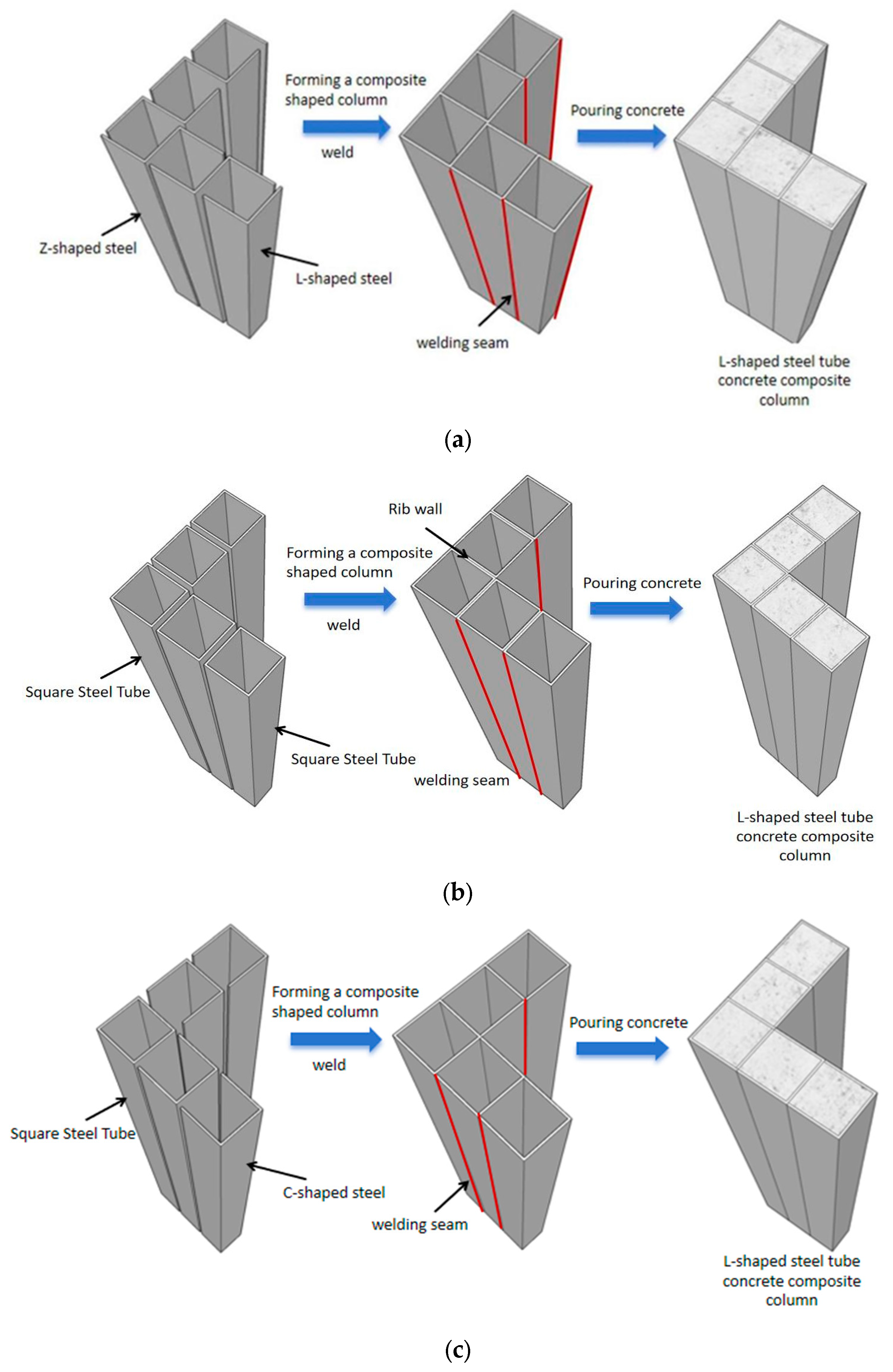
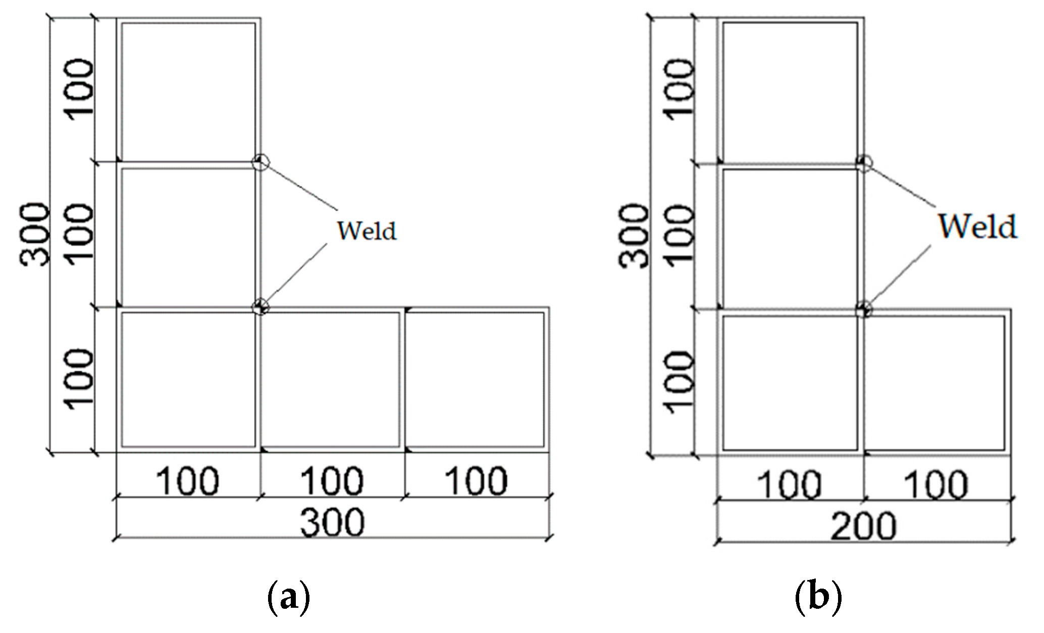
2.1. Specimen Design and Construction
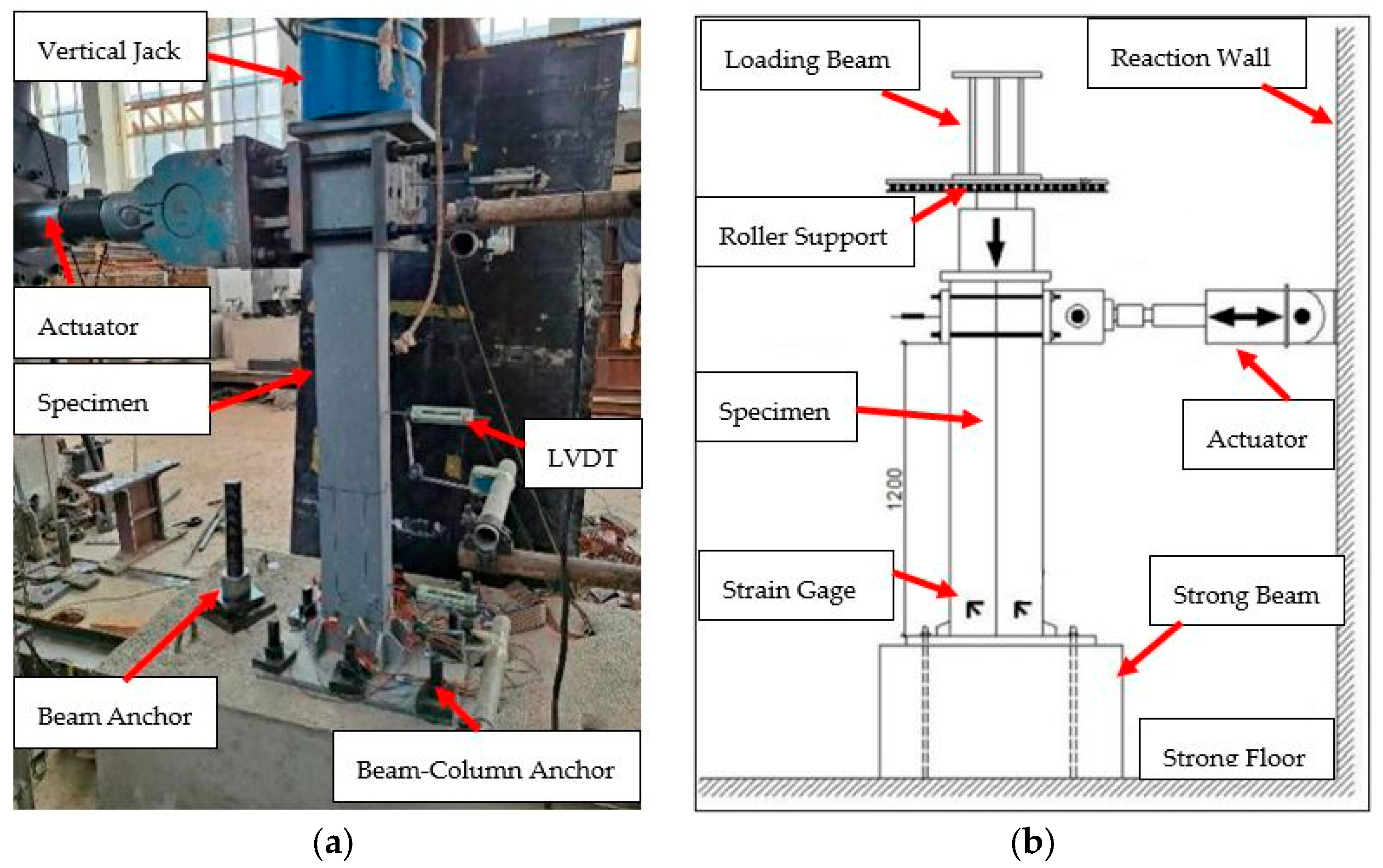
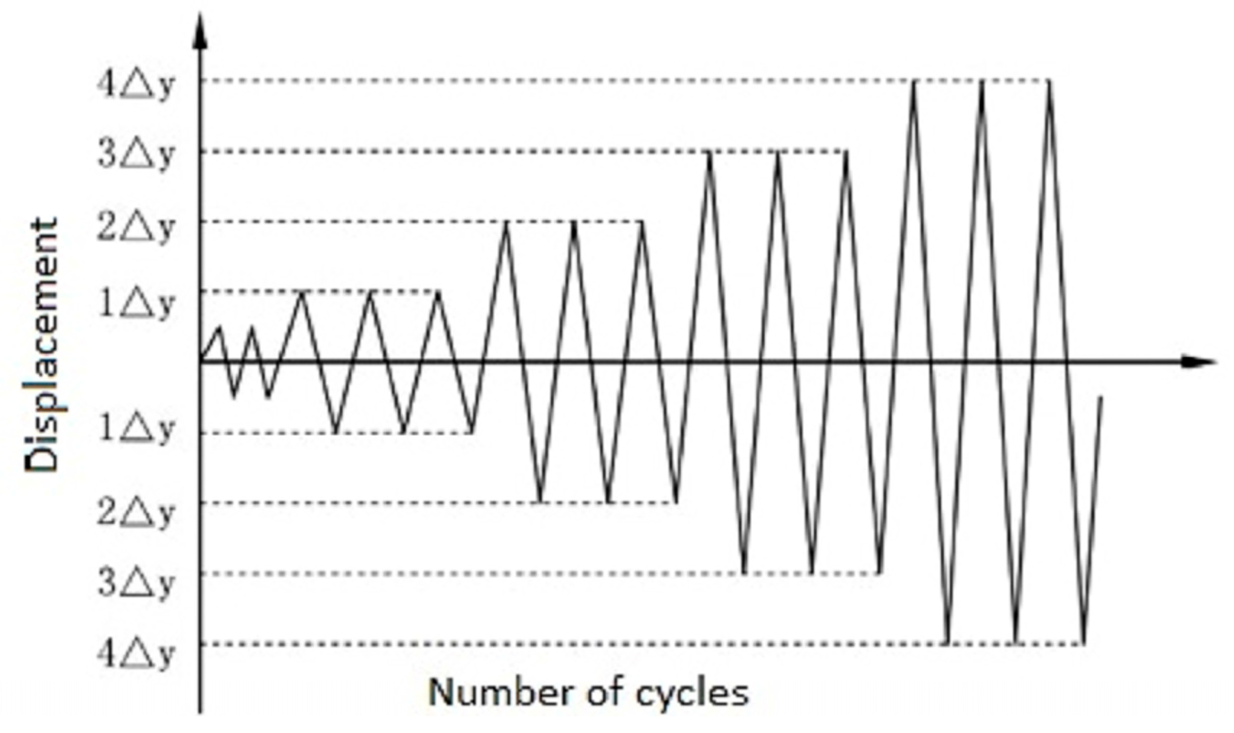
Nine test specimens were designed and constructed on a scale of ½ and tested under cyclic loading. The test specimens are categorized into Z-Series, F-Series, and C-Series. Z-Series L-shaped CFST columns are made from Z-shape cold-formed steel profiles, as shown in Figure 1a. F-Series L-shaped CFST columns are made from structural square tube sections, as shown in Figure 1b, and the C-series are made from cold-formed steel C- C-section profiles, as shown in Figure 1c. Cold-formed steel L-shaped and plate profiles were also used to close the tubes of the L-shaped CFST columns. The specimens had dissimilar legs, with the long leg being b1 = 300 mm and the short leg being either b2 = 200 mm or 300 mm, as shown in Figure 2. Therefore, the length-to-length ratio of the long leg to the short leg b1/b2 is 1 and 1.5, respectively. The steel tube has a wall thickness of 3.75 mm, denoted by the variable t. The specimen’s height was 1500 mm and a summary of the test specimens is given in Table 1. The steel tubes are fabricated from structural steel Q235 with a nominal strength of 235 MPa using the penetration welding technique, as shown in Figure 2. To determine the material properties of the steel tubes, four standard coupons were extracted from the tube and subjected to testing in accordance with the Chinese code GB/T228-2002 [16]. The tensile stress–strain graph of the four tested materials is shown in Figure 3. The concrete’s cube strength and elastic modulus were measured per the Chinese standard GBJ81-85 [17]. One type of concrete grade C35 was used, with cube strengths of 33.6 MPa and cylinder strength of 25.54 MPa. The summary of the steel materials’ properties is shown in Table 2. In Table 1, the axial compression ratio is calculated based on h = (N/N0); N is the actual axial load applied to the test specimens and N0 = Ac fc + As fy, where Ac is the cross-sectional area of the core concrete inside the steel tube); fc is the standard value of concrete axial compressive strength, which can be taken as 0.76 fcu; fy is the measured yield strength of the steel plate; and As is the cross-sectional area of the steel tube.

2.2. Test Setup

The test was conducted at the Yunnan Earthquake Engineering Research Institute, Kunming University of Science and Technology. Figure 4a shows that the specimen was placed vertically and fixed with the ground beam using high-strength nut bolts and the beam was also restrained to the strong ground floor. Figure 4b illustrates the setup for collecting measurements. To capture horizontal displacement at the column’s top, linear variable differential transformers (LVDTs) were employed. Additionally, two more LVDTs were positioned horizontally within the bottom and middle of the column. For stress analysis, strain gauges were affixed to the bottom of the column, which is expected to be the stress–strain concentration zone, as shown in Figure 4b.
The test specimen underwent a dual-loading scenario involving a consistent axial load alongside cyclically lateral loads. An axial load of 400 kN was initially imposed on CD-1, FD-1, and ZD-1 and 320 kN was applied to the rest of the specimens prior to applying any lateral loads. The axial load was completely administered to the specimens after the pre-loading stage. Subsequently, after a brief interval of 2 to 3 min, the lateral load was introduced at the upper section of the column through the application of cyclically varying displacements, as shown in Figure 5. This lateral loading procedure was carried out in adherence with the seismic testing guidelines outlined by seismic testing of structures JGJ/T 101 [18]. The lateral loading cycles were executed using a displacement control as the governing method. The experimental procedure was initiated by subjecting the specimen to two loading cycles at predefined lateral displacement levels: 0.25∆y, 0.5∆y, and 0.75∆y, which ∆y, indicating the lateral displacement of the specimen corresponding to 75% of the anticipated lateral cyclic load-bearing capacity of the L-shaped CFST column. Subsequently, the testing protocol involved three cycles at displacement increments of 1∆y, 2∆y, 3∆y, 4∆y, and so forth. This progressive loading sequence continued until the lateral load reached 85% of the maximum load-bearing capacity of the specimen. ∆y was determined based on a numerical nonlinear fiber section beam–column model to analyze the relationship between lateral loads and lateral displacement in CFST columns. This model divides the nonlinear fiber beam–column into multiple segments along its length and each segment is further sliced at its midpoint. Within these slices, discrete fibers are used to represent the cross-sectional properties. Each fiber is characterized by its area, distance from the centroidal axis of the cross-section, and a stress–strain relationship in one direction. In order to obtain the response of the fibers in terms of force and deformation, the stress–strain responses of all the fibers are integrated across the cross-section. These slice force–deformation responses are then integrated along the entire length of the column to derive the overall force–displacement response of the column.

3. Experimental Results
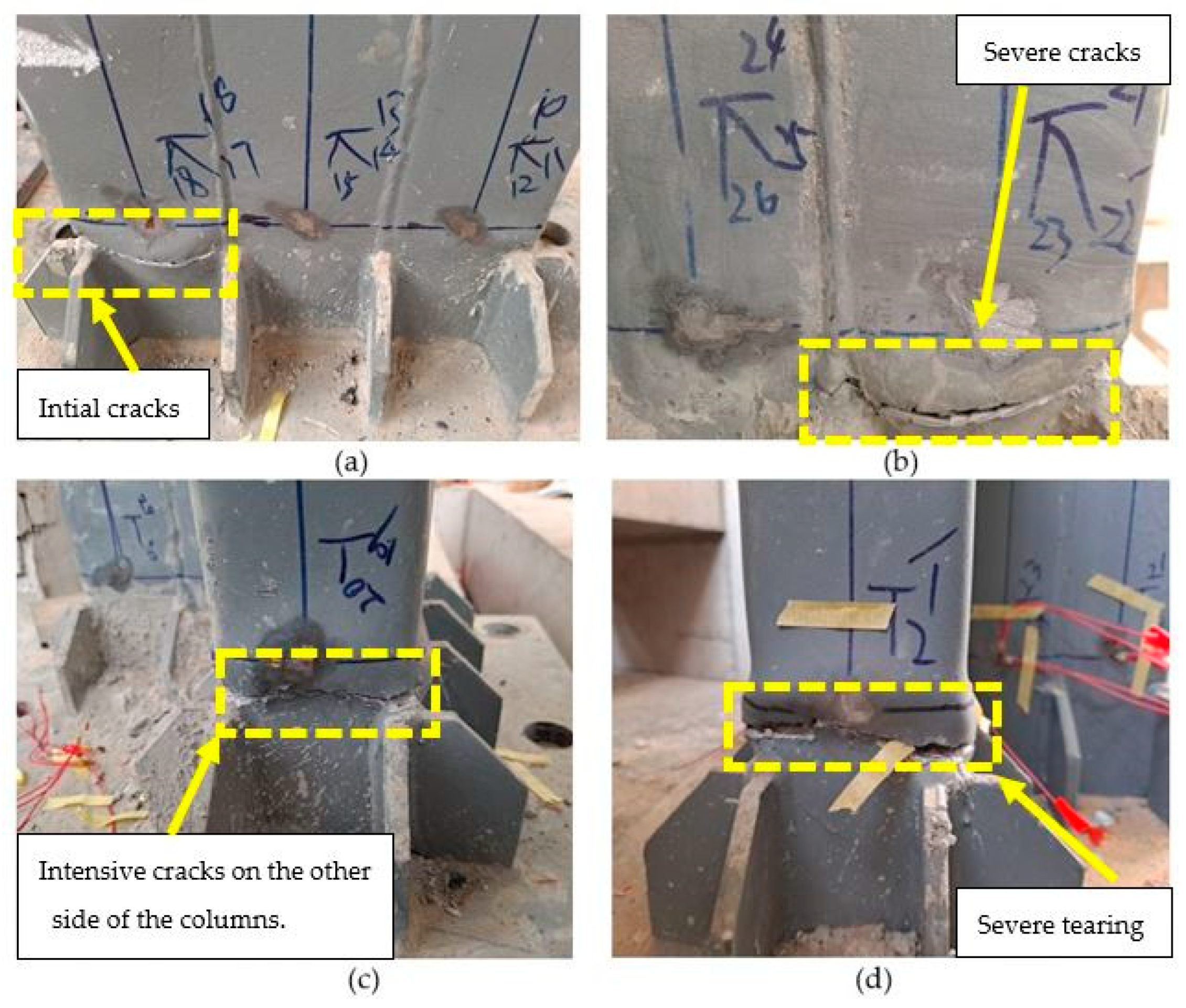
3.1. Falire Mode

All the L-shaped CFST columns exhibited ductile behavior during testing. The failure in each specimen was characterized by either outward bulging at the bottom of the tube or tears across the welded tube plates. No external bulges were observed before reaching a lateral displacement of 1∆y, indicating that the specimens were still within the elastic stage. Specimen CD-1, FD-1, and ZD-1 had similar deformation during the cyclic loading. A visible bulging phenomenon appeared when the lateral load increased to 3∆y. This phenomenon occurred on the steel tube 30 mm above the corner rib at the bottom of the specimen, as shown in Figure 6a. After the specimen reached its peak load, the bulging at the bottom of the specimen intensified as the displacement gradually increased. At the same height, bulging appeared on the other external corner surface. During the advanced loading phase, there was a continuous decline in the load-bearing capacity of the specimen, primarily attributed to the heightened occurrence of buckling and cracking on the steel tube’s surface, particularly in the region initially affected, as visually represented in Figure 6b. With increasing displacement resulting from steel tube cracking, these cracks gradually expanded and propagated in both directions. The presence of tensile fractures indicated that the internal concrete had undergone compression failure, rapidly reducing the applied load. After the applied load decreases to 85% of its peak value, the specimen stops loading and significant damage occurs to the specimen, as shown in Figure 6c,d.
The failure mechanisms observed in specimens Z-1, F-1, and C-1 were similar during the elastic loading phase. All three sets of specimens exhibited initial buckling of the steel tube at the base of the column, as illustrated in Figure 7a,b. As the loading progressed, this buckling phenomenon intensified, eventually leading to specimen failure. Table 1 presents an analysis of the loading direction, which was considered along the long leg (X) and short leg (Y) to assess the seismic performance of L-shaped CFST columns with dissimilar leg lengths under cyclic loading conditions. The results underscore the loading direction’s substantial influence on these columns’ seismic behavior. When the loading increased to 3∆y, a bulge appeared in the bottom of the extended leg of the long leg and gradually deformed. When the displacement increases, the cracks in the steel tube widen and extend. This is because the concrete inside the tube has been crushed, which causes the applied load to decrease rapidly. The same failure mode was observed in specimen C-2 which was loaded in the short leg. The cracks and tearing were concentrated on the short leg. When the applied load decreases to 85% of its peak value, the specimen stops loading and significant damage occurs, as shown in Figure 6c,d.

3.2. Hysteresis Behavior

Hysteresis behavior differs between the load–displacement response during and in unloading in cyclic loading. This difference is caused by the energy dissipation in the material or structure during loading. The hysteresis behavior of a material or structure is vital in many applications, such as earthquake engineering. In earthquake engineering, hysteresis behavior is crucial in assessing a structure’s capacity for dissipating energy. This capacity is vital for the structure’s ability to withstand the forces generated during seismic events [19].
Figure 8 illustrates the hysteresis loops characterizing the behavior of L-shaped CFST columns. All columns exhibit elastic behavior in the initial stage, characterized by a linear load–displacement relationship. However, as lateral displacement increases, the columns experience a gradual degradation in stiffness, transitioning into the inelastic stage. A reduction in the strength and stiffness of the structure after each cycle of loading and unloading characterizes the pinching effect. In the later stages of testing, a subtle pinching effect is observed in the hysteresis loops of specimen F-1, as depicted in Figure 8a. Notably, Figure 8b reveals an absence of pinching phenomena in the hysteresis loops of specimens subjected to loading along the Y direction, with specimen F-2 exhibiting significantly lower load-bearing capacity. A similar hysteresis response is observed in specimens C-1, C-2, Z-1, and Z-2, as depicted in Figure 8c–f.

3.3. Skeleton Curve Response

The skeleton curve is a valuable tool for understanding the cyclic loading behavior of materials and structures. It can predict the performance of these materials and structures under various loading conditions. The study obtains the envelope curve by plotting the maximum load from each hysteresis loop against the displacement [20]. The specimens had very similar positive and negative bearing capacities, which indicates that the specimens had almost symmetrical shear performance in both directions (positive and negative). Figure 9 shows the skeleton curves of the specimens; the smooth S-shaped curves of the specimens’ skeleton curves show that the loading mechanism goes through three stages: elastic when the material stretches but does not permanently deform; elastic–plastic when the material starts to deform permanently; and ruptured when the material breaks. A summary of the skeleton curves of all specimens is also presented in Table 3.
Specimen FD-1 and F-1 exhibited the highest peak load and lateral deformation, indicating that the structural square tube sections provide a higher confinement ratio than other specimens. CD-1, ZD-1, and C-1, Z-1 of the L-shaped CFST columns exhibit similar load-bearing capacity and lateral deformation. Specimen F-2, C-2, and Z-2 showed the lowest load-bearing ability, indicating the direction of loading had a significant impact.

3.4. Bearing Capacity Degradation

Calculating the degradation of bearing capacity in columns under cyclic loading is crucial for assessing the structure’s seismic resilience during earthquakes or repeated loading events. By investigating the reduction in load-carrying ability over repeated loading cycles, valuable insights can be gained into such columns’ structural integrity and performance. The author proposed the bearing degradation coefficient in this study, which can be calculated using the following Equation (1).
S i = P i P m a x
In Equation (1), Si indicates the bearing degradation coefficient in each loading cycle; Pi indicates the lateral load during each cyclic and Pmax is the maximum load-bearing capacity of the specimen. The bearing degradation coefficient of specimens is determined based on Equation (1) and the result is shown in Figure 10. All specimens showed a stable and gradual degradation in bearing capacity after cycles 14 and 15; when the loading reached cycle 25, the bearing capacity decreased significantly and the loading stopped.

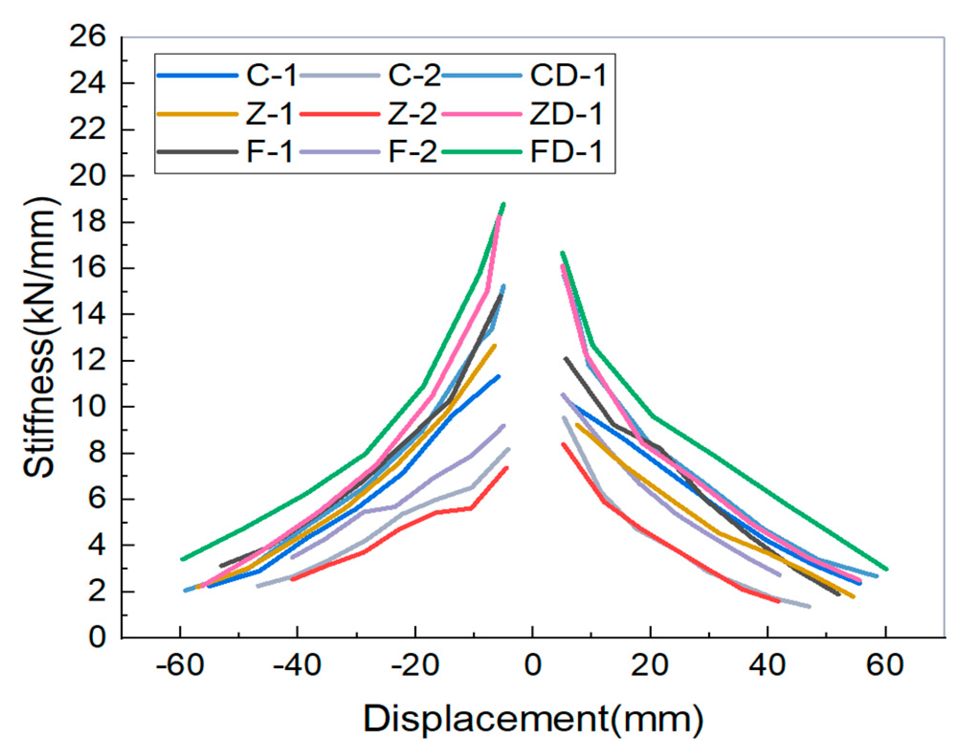
3.5. Stiffness Degradation

The degradation of stiffness is a critical consideration when designing columns for structures exposed to cyclic loading, particularly in regions prone to seismic activity. In this research, we employed Equation (2), known as the secant stiffness K method, as recommended by the specification of testing methods for earthquake-resistant buildings JGJ/T 101 [21], to calculate the stiffness degradation of the specimens under examination.
K = P i + P i i + i
Pi and −Pi is the lateral force of the specimen at the peak of the first cycle in each stage in the positive and negative directions, respectively, and Di and −Di are the corresponding lateral displacements in the positive and negative directions, respectively.
The evolution of stiffness degradation provides valuable insights into the structural behavior and aids in design considerations. The secant stiffness K and lateral displacement of the specimens are shown in Figure 11”.
From Figure 11, specimen FD-1 exhibits the highest stiffness, 19.30 kN/mm; on the other hand, specimen Z-2 had 7.12 kN/mm, which indicates the lowest stiffness. Overall, the stiffness degradation observed slowly decreases after the cyclic loading increased. It is because of the failure of the bottom of the column, which started from minor cracking to wider tearing of the steel tubes and infill concrete.

3.6. Energy Dissipation Capacity

Energy dissipation is pivotal in evaluating a structure’s capability to absorb and disperse energy during seismic events or cyclic loading. It signifies the structure’s aptitude for experiencing inelastic deformations while concurrently diminishing the energy transfer. Evaluating energy dissipation in specimens yields valuable insights into their seismic performance.
To quantify the energy dissipation of specimens, a commonly employed method involves measuring the area encompassed by the hysteresis loops [22,23]. This enclosed area signifies the energy absorbed and dissipated during cyclic loading. Two widely accepted metrics for assessing energy dissipation are the energy dissipation coefficient (E) and the equivalent viscous damping coefficient (ζe) [21]. “The energy dissipation of specimens can be gauged using either the energy dissipation coefficient E or the equivalent viscous damping coefficient ζe, as outlined in JGJ-101 [21], which is derived from the area enclosed by the hysteresis loops. A larger enclosed area within the hysteresis loop corresponds to higher values of E or ζe, indicating more robust energy dissipation characteristics. The calculation for ζe is as follows”:
E = S ( A B C + C D A ) S ( O B E + D O F ) ,   or   ζ e = 1 2 π S ( A B C + C D A ) S ( O B E + D O F )
where S ( A B C + C D A ) is the dissipated energy in a loading cycle on the hysteresis curve and S ( O B E + D O F ) is the energy consumed by a linear elastic body equivalent to the specimen, defined by the areas surrounded by the triangles O B E and D O F , as shown in Figure 12a. In this study, the equivalent viscous damping coefficient ζe was used to assess the energy dissipation capacity of the test specimens. The results are shown in Figure 12b. Specimen F-2 was measured with the highest energy dissipation coefficient, indicating the hysteresis loop in this specimen is complete and has no pinching. On the other hand, specimen FD-1 showed lower energy dissipation. Overall, the average energy dissipation coefficient was over 0.3, indicating that specimens are robust enough to resist significant earthquakes.

3.7. Ductility

According to the specification for seismic testing of structures JGJ-101 [21], the skeleton curve of a structure can be used to calculate various parameters, such as the yield load (Py), maximum load (Pmax), ultimate load (Pu), and displacement ductility, as shown in Table 3.
If the skeleton curve does not exhibit a distinct yield point, the yield load (Py) and corresponding yield displacement (∆y) can be determined using the reciprocal area method, as shown in Figure 13a. This method involves dividing the area under the envelope curve (1) up to a certain displacement by the area under the curve after that displacement (2). The yield displacement at which the two areas are equal is [20].
The peak load (Pmax) is the maximum load on the envelope curve. The ultimate load (Pu) is 85% of the peak load and corresponds to the ultimate displacement (∆u). The displacement ductility factor (µ) of the specimen is defined as the ratio of the ultimate displacement (∆u) to the yield displacement (∆y), as shown in Figure 13b.
Figure 13b shows that specimen F-2 exhibits the highest displacement ductility and that specimen Z-2 shows the lowest. Overall, the average displacement ductility was measured at 2.32, which indicates the specimen had a great ductility response under cyclic loading.

4. Conclusions

The primary focus of this study was to conduct experimental research on how L-shaped CFST columns respond when subjected to both a constant axial load and cyclic lateral load acting in combination. The combination of steel tubes and the loading direction were investigated. Based on the findings of the present investigations, the following conclusions can be drawn:
  • All L-shaped CFST columns examined in the tests displayed well-rounded hysteretic loops, demonstrating favorable energy dissipation and ductility characteristics, ultimately experiencing a ductile failure mode;
  • The loading direction of L-shaped CFST columns significantly impacted the load-bearing capacity of the specimen, such as the specimens F-1, C-1, and Z-1, on the long leg loading direction, which had 206, 177, and 93. kN maximum load-bearing capacity. On the other hand, specimens F-2, C-2, and Z-2 with short leg loading direction exhibited 134, 93, and 93 kN peak load-bearing capacity, respectively;
  • Specimen FD-1 showed the highest peak load-bearing by 253 kN with a corresponding ultimate 50.3 mm lateral deformation, which indicates the steel tube increased the confinement ratio of the L-shaped CFST columns;
  • All specimens failed because of significant infill concrete damage and the bottom of the column steel tube tearing and fractures. The cracks and fractures of the steel tubes were measured almost at 30–50 mm above the beam–column connections.
L-shaped CFSTs exhibit remarkable seismic performance, positioning them for widespread utilization in building structures, particularly within earthquake-prone areas. This study contributes fresh seismic behavior data for L-shaped CFST columns, which is valuable for advancing theoretical models. Nevertheless, it is imperative to recognize the need for future studies to thoroughly investigate the seismic response of L-shaped CFST columns with beam connections under cyclic and axial loading conditions.

Author Contributions

D.H., Methodology; Z.T., Supervision, Conceptualization, Investigation, and Funding acquisition; W.A.G., Writing—review and editing; M.M.H., Editing; W.X., T.W., K.Z. and H.D., Project administration and supervision. All authors have read and agreed to the published version of the manuscript.

Funding

This research was funded by the Key Research and Development Programs (Key R and D programs) department of the Science and Technology Department of Yunnan province, the Faculty of Civil Engineering and Architecture, Kunming University of Science and Technology, number 202003AC100001.

Data Availability Statement

The data supporting this study’s findings are available on request from the corresponding author.

Conflicts of Interest

The authors declare no conflict of interest.

References

  1. Dong, X.; Wang, L.; Xu, Z.; Liu, L.; Guan, S.; Chen, H. Cyclic performance of T-Shaped CFST column to steel beam joint with vertical stiffener. Structures 2023, 55, 1659–1674. [Google Scholar] [CrossRef]
  2. Zheng, Y.; Liang, W.; Ma, S.; Zeng, S. Behavior of stiffened and multi-cell L-shaped CFST columns under eccentric compression. Thin-Walled Struct. 2022, 174, 109156. [Google Scholar] [CrossRef]
  3. Yang, Y.; Wang, G.; Yang, W.; Wei, X.; Chen, Y.F. Experimental research on fire behavior of L-shaped CFST columns under axial compression. J. Constr. Steel Res. 2022, 198, 107505. [Google Scholar] [CrossRef]
  4. Cai, W.-Z.; Wang, B.; Shi, Q.-X. Hysteretic model and seismic energy response of CFST columns in diagrid structure. J. Build. Eng. 2023, 68, 106185. [Google Scholar] [CrossRef]
  5. Li, B.; Yang, Y.; Liu, J.; Liu, X.; Cheng, Y.; Chen, Y.F. Behavior of T-shaped CFST column to steel beam connection with U-shaped diaphragm. J. Build. Eng. 2021, 43, 102518. [Google Scholar] [CrossRef]
  6. Xiao, Y.; Bie, X.-M.; Song, X.; Zhang, J.; Du, G. Performance of composite L-shaped CFST columns with inner I-shaped steel under axial compression. J. Constr. Steel Res. 2020, 170, 106138. [Google Scholar] [CrossRef]
  7. Tao, Z.; Hasan, M.M.; Han, D.; Qin, Q.; Abdul Ghafar, W. Study of the Axial Compressive Behaviour of Cross-Shaped CFST and ST Columns with Inner Changes. Buildings 2023, 13, 423. [Google Scholar] [CrossRef]
  8. Shen, Z.-Y.; Lei, M.; Li, Y.-Q.; Lin, Z.-Y.; Luo, J.-H. Experimental study on seismic behavior of concrete-filled L-shaped steel tube columns. Adv. Struct. Eng. 2013, 16, 1235–1247. [Google Scholar] [CrossRef]
  9. Zhang, L.; Zhang, Y.-J.; Tong, J.-Z.; Tong, G.-S.; Fu, B.; Xu, Y.-M. Experimental study on multi-cellular L-shaped CFST slender columns under biaxial eccentric compression. Structures 2022, 45, 2210–2225. [Google Scholar] [CrossRef]
  10. Zheng, Y.; Yang, S.; Lai, P. Hysteretic behavior of multi-cell L-shaped concrete-filled steel tubular columns at different loading angles. Eng. Struct. 2020, 202, 109887. [Google Scholar] [CrossRef]
  11. Zheng, Y.; Zeng, S. Design of L-shaped and T-shaped concrete-filled steel tubular stub columns under axial compression. Eng. Struct. 2020, 207, 110262. [Google Scholar] [CrossRef]
  12. Zhou, T.; Jia, Y.; Xu, M.; Wang, X.; Chen, Z. Experimental study on the seismic performance of L-shaped column composed of concrete-filled steel tubes frame structures. J. Constr. Steel Res. 2015, 114, 77–88. [Google Scholar] [CrossRef]
  13. Chang, X.; Fu, L.; Zhao, H.-B.; Zhang, Y.-B. Behaviors of axially loaded circular concrete-filled steel tube (CFT) stub columns with notch in steel tubes. Thin-Walled Struct. 2013, 73, 273–280. [Google Scholar] [CrossRef]
  14. Ekmekyapar, T.; Ghanim Hasan, H. The influence of the inner steel tube on the compression behaviour of the concrete filled double skin steel tube (CFDST) columns. Mar. Struct. 2019, 66, 197–212. [Google Scholar] [CrossRef]
  15. Zhou, L.; Zhang, Z.; Liu, C.; Shi, G. Experimental and numerical investigation of axially loaded L-shaped box-T section columns. Eng. Struct. 2023, 291, 116412. [Google Scholar] [CrossRef]
  16. GB/T228-2002; Metallic Materials—Tensile Testing at Ambient Temperature. General Administration of Quality Supervision, Inspection and Quarantine of the People’s Republic of China: Beijing, China, 2002.
  17. GBJ/81-1985; Testing Methods for Mechanical Performance of Ordinary Concrete. General Administration of Quality Supervision, Inspection and Quarantine of the People’s Republic of China: Beijing, China, 1985.
  18. JGJ/T 101-2015; Specification for Seismic Test of Buildings. Housing and Urban-Rural Development: Beijing, China, 2015.
  19. Wahab, A.G.; Zhong, T.; Wei, F.; Hakimi, N.; Ahiwale, D.D. Seismic performance enhancement of RC framed structures through retrofitting and strengthening: An experimental and numerical study. Asian J. Civ. Eng. 2023. [Google Scholar] [CrossRef]
  20. Abdul Ghafar, W.; Zhong, T.; Abid, M.; Faizan, E.; Mohamed, A.; Yosri, A.M. Seismic performance investigation of an innovative steel shear wall with semi-rigid beam-to-column connections. Front. Mater. 2022, 9, 1075300. [Google Scholar] [CrossRef]
  21. JGJ-101; Specification of Testing Methods for Earthquake Resistant Building. China Architecture and Building Press Beijing: Beijing, China, 2015.
  22. Huangfu, S.-E.; Tao, Z.; Zhang, J.; Ghafar, W.A.; Wang, Z.; Ye, C.; Hasan, M. Flexural Behavior of Stainless Steel V-Stiffened Lipped Channel Beams. Metals 2023, 13, 434. [Google Scholar] [CrossRef]
  23. Abdul Ghafar, W.; Tao, Z.; Tao, Y.; He, Y.; Wu, L.; Zhang, Z. Experimental and Numerical Study of an Innovative Infill Web-Strips Steel Plate Shear Wall with Rigid Beam-to-Column Connections. Buildings 2022, 12, 1560. [Google Scholar] [CrossRef]
Figure 1. The buildup process of various series of specimens: (a) Z-Series, (b) F-Series, and (c) C-series.
Buildings 13 02320 g001
Figure 2. The Test specimen plan view: (a) similar-leg L-shaped CFST and (b) dissimilar-leg L-shaped CFST.
Buildings 13 02320 g002
Figure 3. The tensile stress–strain curve from the coupon test.
Buildings 13 02320 g003
Figure 4. Test setup and instrumentations: (a) test photo and (b) configuration of the instruments.
Buildings 13 02320 g004
Figure 5. Cyclic loading amplitude.
Buildings 13 02320 g005
Figure 6. Failure modes of CD-1, FD-1, and ZD-1 specimens during the test. (a) Initial cracks at the bottom of the columns. (b) Severe cracks at the steel tube and buckling of the columns. (c) Intensive cracks on the other side of the columns. (d) Complete tearing and failure of the columns.
Buildings 13 02320 g006
Figure 7. Failure modes of C-1, F-1, and Z-1 specimens during the test. (a) Initial cracks at the bottom of the columns. (b) Severe cracks at the steel tube and buckling of the columns. (c) Intensive cracks and buckling on the long leg of the columns. (d) Severe tearing and failure of the short leg of the columns.
Buildings 13 02320 g007
Figure 8. The hysteresis response of the specimens: (a,b) long and short leg direction loading specimen F-1 and F-2, respectively; (c,d) long and short leg direction loading specimens C-1 and C-2, respectively; (e,f) long and short leg direction loading specimens Z-1 and Z-2, respectively; and (gi) similar leg specimens FD-1, CD-1, and ZD-1, respectively.
Buildings 13 02320 g008aBuildings 13 02320 g008b
Figure 9. Skeleton curve of the specimens.
Buildings 13 02320 g009
Figure 10. The degradation of bearing capacity.
Buildings 13 02320 g010
Figure 11. Stiffness degradation curves of the specimens.
Buildings 13 02320 g011
Figure 12. The energy dissipation of the specimens is depicted as follows: (a) illustrates the definition of the energy dissipation coefficient while (b) compares the energy dissipation coefficients among the test specimens.
Buildings 13 02320 g012
Figure 13. Ductility calculation: (a) the principle of area reciprocity and (b) the specimen displacement ductility factor.
Buildings 13 02320 g013
Table 1. The specimen details.
Speciment (mm)b1/b2Loading DirectionAxial Compression Ratio (h)Concrete GradeSteel Grade
Z-13.751.5X0.3C35Q235
Z-23.751.5Y0.3C35Q235
F-13.751.5X0.3C35Q235
F-23.751.5Y0.3C35Q235
C-13.751.5X0.3C35Q235
C-23.751.5Y0.3C35Q235
ZD-13.751X0.3C35Q235
FD-13.751X0.3C35Q235
CD-13.751X0.3C35Q235
Note: The test specimen are named: Z-1and Z-2, representing the Z-series with dissimilar-leg; F-1 and F-2, depicting the F-series with dissimilar-leg; C-1 and C-2, representing the C-series with dissimilar-leg; and the specimen ZD-1, FD-1, and CD-1 describing the above series with the similar-leg size L-shaped CFST columns, respectively.
Table 2. Mechanical properties of the steel.
Copoun Test SpecimensYield Strength fy
(MPa)
Ultimate Strength fu
(MPa)
Elastic Module E (GPa)
Z-1303.8428.6200
L-1272.7384.7196
C-1280.0395.0196
F-1310.1368.7200
Note: Z-1, F-1, C-1, and L-1 coupon test specimens are taken from Z, square, C, and L-shaped steel profiles.
Table 3. Summary of the test result.
SpecimenPy (kN)y (mm)Pmax (kN)max (mm)u (mm)µ
F-1198.8921.57205.5429.3744.872.08
F-2118.7615.77133.9830.4341.912.65
C-1160.0421.96177.4831.7647.792.18
C-277.4014.0793.4025.0036.732.61
Z-1153.0121.66165.9931.5742.931.98
Z-277.9914.7192.9523.7034.122.32
FD-1219.9721.54252.8530.8050.302.34
CD-1166.9419.68195.9229.3048.012.44
ZD-1161.7619.98189.5527.8246.402.32
Note: Py is the yield load corresponding to ∆y yield displacement and Pmax is the peak or the maximum load corresponding to ∆max, the maximum lateral displacement of the specimen. The ultimate load (Pu) is 85% of the peak load and corresponds to the ultimate displacement (u).
Disclaimer/Publisher’s Note: The statements, opinions and data contained in all publications are solely those of the individual author(s) and contributor(s) and not of MDPI and/or the editor(s). MDPI and/or the editor(s) disclaim responsibility for any injury to people or property resulting from any ideas, methods, instructions or products referred to in the content.

