1. Introduction
Construction is a key industry that significantly contributes to the global gross domestic product (GDP), accounting for approximately 6% of the global GDP and generating annual revenues of approximately
$10 trillion [
1,
2]. However, the productivity of the construction industry lags compared with that of other sectors [
3]. Historically, the industry has been prone to errors, high costs, and interference [
4,
5,
6].
Steel structures have recently gained increased attention owing to their strength, durability, and efficiency [
7,
8]. However, the lack of coordination among the different parties involved in construction projects has become a common problem that causes delays, cost overruns, and low project quality [
1,
4,
6]. This problem is particularly severe in steel construction, where supply chain fragmentation and the lack of communication between engineers, fabricators, designers, and contractors have led to problems in planning, design, fabrication, transportation, and erection [
1,
9,
10,
11,
12].
A steel construction project consists of several phases, ranging from material and fabricator selection to the erection and finishing of the structure [
1,
13,
14]. As the use of steel in construction increases, the complexity of projects also increases, especially in terms of information management [
1,
12,
15,
16]. The quality and timeliness of information in different stages of the workflow must be ensured to avoid the repetition of processes and interference and reduce the associated costs and construction time [
12,
16]. The inefficient use of information causes fragmentation of a steel project lifecycle. Therefore, information technologies that facilitate collaboration between the different stages of a project must be adopted [
10,
11,
12].
The development of computer-aided design (CAD) software in the 1980s allowed engineers and architects to create accurate and detailed technical drawings in reduced time [
17]. The evolution of CAD to building information modeling (BIM) has allowed the creation of detailed three-dimensional (3D) models and a database of project information [
8,
13,
15,
16,
17,
18,
19] for different application in construction [
20], urban planning [
21,
22,
23], and indoor navigation [
24,
25]. BIM also promotes collaboration between team members [
26]. It has become a standard tool in the construction and civil engineering industries to improve the efficiency and accuracy in the planning, design, and construction process [
8,
13,
15,
16,
17,
18,
19].
In recent decades, the construction industry has undergone a technological revolution; in particular, BIM has become an essential tool that encompasses a series of activities aimed at improving the outcomes of different project stages [
11,
15,
17,
19].
Although utilizing steel in construction has advantages, the usefulness of BIM has not yet been explored in detail [
1,
9]. The efficient management in the planning, design, fabrication, transport, and erection phases of a construction project maximizes the benefits of working with steel. However, the lack of coordination between different teams can cause problems [
1,
9]. The adoption of information technologies that facilitate collaboration between the teams ensures the quality and timeliness of information and reduces the costs and construction time [
1,
9,
27].
The utilization of BIM in steel construction can enhance the coordination between diverse project stakeholders and facilitate efficient information management in all the project phases [
1,
28]. BIM allows the creation of a 3D digital model that integrates all project-related information, ranging from drawings and technical specifications to costs and planning [
1,
9,
20,
29,
30]. This enables collaboration between stakeholders by providing access to the same information so that they can work together in real-time to solve problems [
1,
28,
31].
However, BIM must be applied with standards and tools that allow the integration of project information [
9,
32,
33]. These standards include the Information Delivery Manual (IDM), which defines the processes, protocols, and formats for information exchange between stakeholders. By following the IDM guidelines, the project information can be standardized [
32,
34,
35].
Another important standard is the Industry Foundation Classes (IFC), which enables the exchange and sharing of BIM data between different software and tools used in construction [
36,
37,
38,
39]. Information-sharing between stakeholders in a construction project improves the communication efficiency and reduces errors and misunderstanding [
1,
9,
33,
36,
37,
38].
The CAD-BIM methodology is an integrated approach that combines CAD and BIM to enhance the design and construction processes in the architecture, engineering, and construction industry. This methodology has proven to be effective in information management for steel construction projects. However, it is unable to solve all the problems encountered in the industry [
40,
41]. In contrast, BIM for the design, fabrication, and erection of steel buildings, abbreviated BIM-DFE [
1], considers the lifecycle of a project with emphasis on early integration. It focuses on the fabrication process, which accounts for the largest resource expenditures [
1,
9].
The CAD-BIM methodology has been widely used by the construction industry, with IDM as a guide for deliverables and IFC for information transfer in general construction projects [
32,
42,
43,
44,
45,
46,
47]. However, these tools have failed to fully integrate the benefits of BIM into other construction subprocesses (e.g., steel construction) owing to their holistic nature [
9]. Recent studies on the application of BIM in steel construction (e.g., BIM-DFE) have been validated by the academic community and industry. A Delphi study showed that the BIM-DFE methodology enhanced the utilization of BIM in steel construction projects [
1]. However, the methodology has not been tested in real-world cases. Therefore, one of the primary objectives of this study is to assess the applicability of recent methodologies related to BIM and steel construction in real-world scenarios [
44,
48].
1.1. BIM-DFE
BIM for the design, fabrication, and erection of steel buildings (BIM-DFE) is a comprehensive approach that integrates digital technologies and collaborative workflows to optimize steel construction projects. The BIM-DFE method can facilitate communications between all the parties involved (e.g., client, designers, fabricators, erectors, etc.) to ensure the success of the project. It leverages BIM at all stages of the steel construction lifecycle. A 3D BIM model is fed with information at different stages of the project (e.g., planning, design, fabrication, transportation, and erection) [
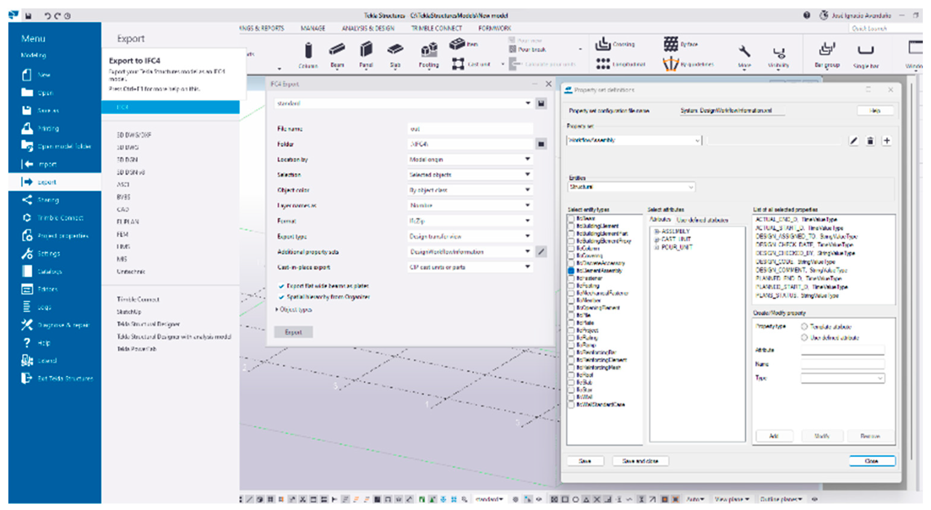
1]. Information is transferred using open BIM collaboration files in the IFC format, as it plays a crucial role in ensuring efficient data exchange and enabling integration among diverse software platforms [
9]. The use of BIM in planning and design is crucial to obtain a clear understanding of the costs of fabrication, transportation, and erection of steel structures. The BIM-DFE approach emphasizes the integration of stakeholder resources from the outset to achieve the optimal design. This integration focuses on the planning and design phases, in which preliminary analyses were conducted to improve the understanding of decision-makers. BIM models should include relevant information for the transportation simulation in the design phase. This allows the classification and tracking of the components to be transported, which enables the prioritization of transportation according to the needs of the project. Although this information is often excluded, its inclusion can have a significant impact on the total cost of the project [
1,
9].
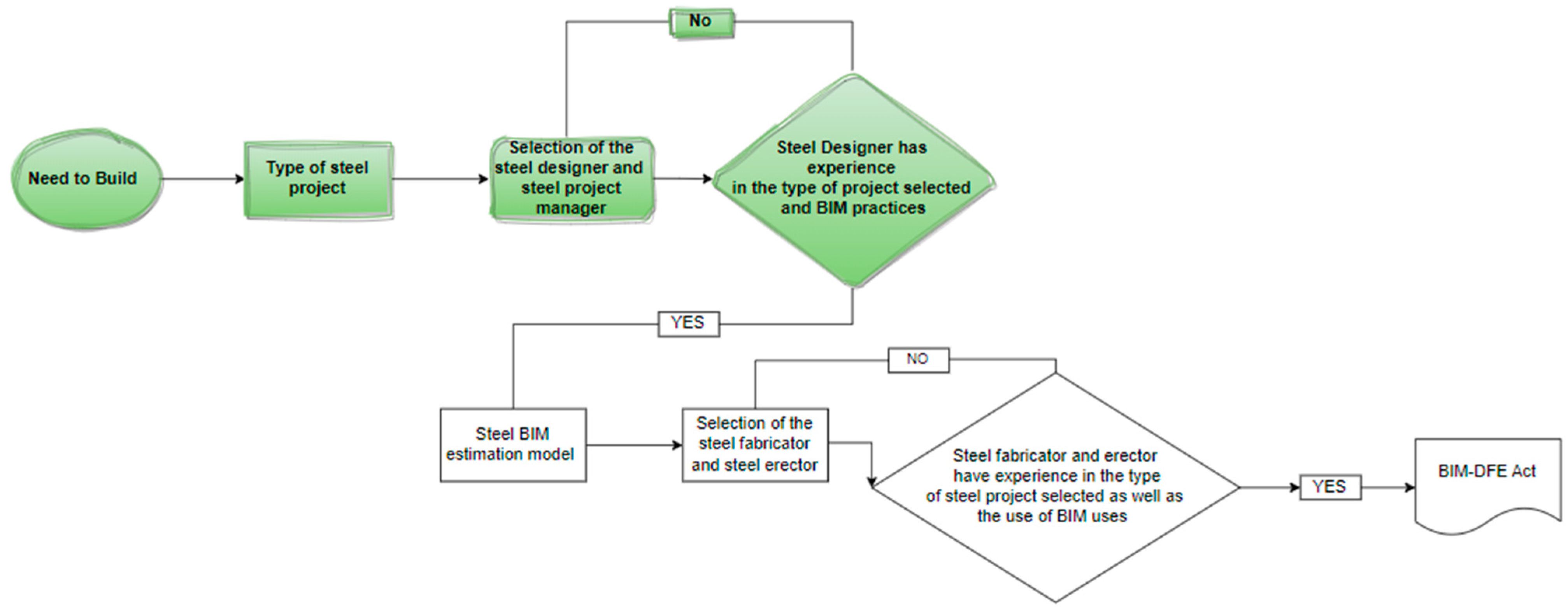
1.1.1. BIM-DFE Steel Planning Phase
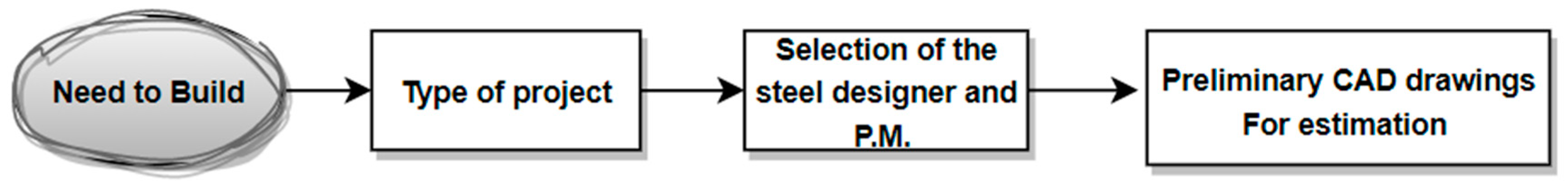
To effectively manage a project, the project type (industrial, commercial, public, etc.) must be selected in the planning phase. A notable process in BIM-DFE is the selection of a project manager to assume the role of a design engineer, who possesses skills and experience in BIM projects. If no qualified project manager is found, then another search is conducted. This is a basic requirement because the project manager is tasked with generating the 3D estimation model [
1].
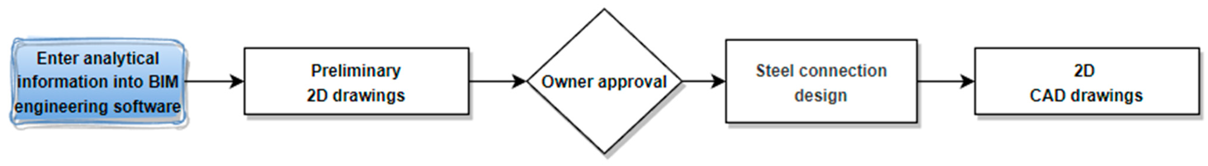
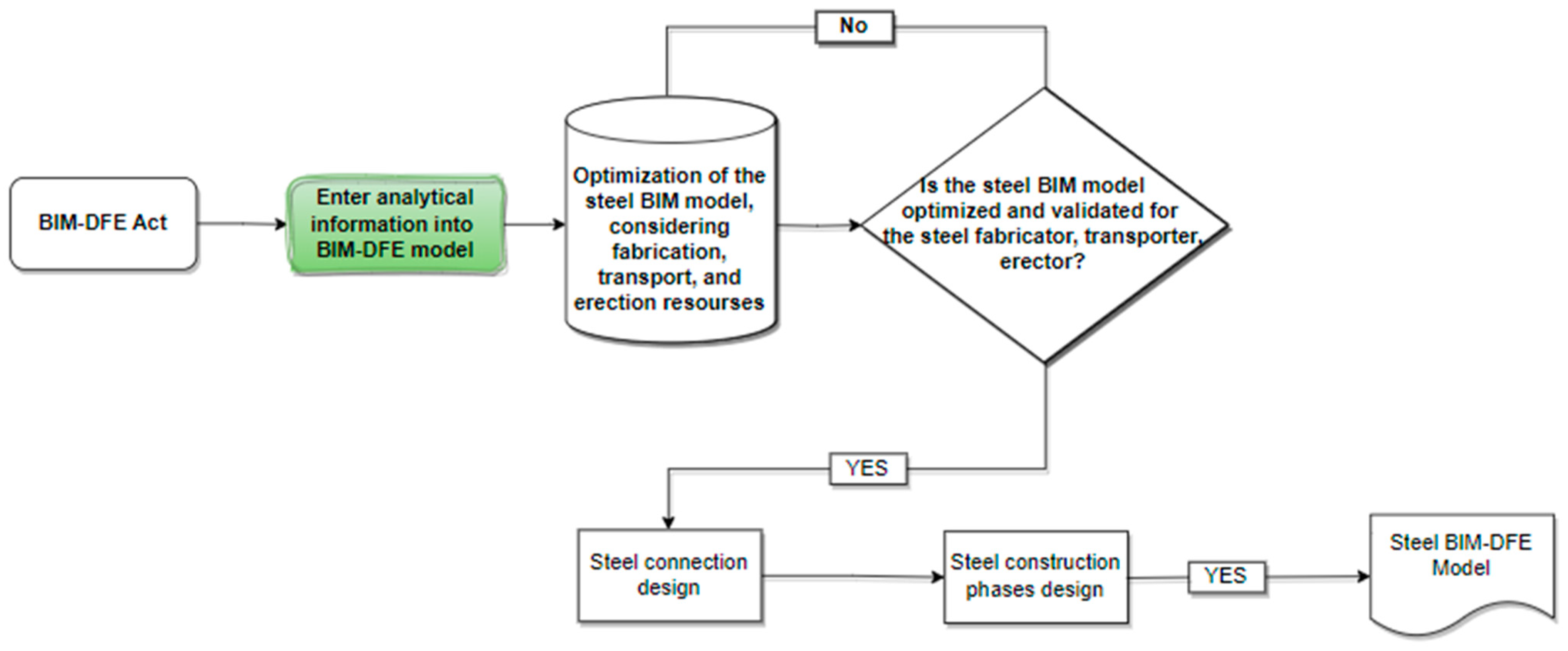
1.1.2. BIM-DFE Steel Design Phase
In the design phase, the model is analyzed for the purpose of optimization. Once the model is optimized, a meeting is held with the client to determine the resources consumed by optimization. The model is optimized until it is approved by the client. Then, the design team verifies the connections using specialized software. When the entire model is approved, it goes through several stages and sequences so that the information in the model can be easily understood by the fabrication team. This model is called the Steel BIM-DFE model [
1].
1.1.3. BIM-DFE Fabrication Phase
In the fabrication phase, detailed engineering and planning for fabrication are simultaneously conducted to optimize the transportation resources. Then, the components are fabricated, and the final 3D model approved in the previous phases is generated. This model is shared through the common data environment to provide information to stakeholders [
1].
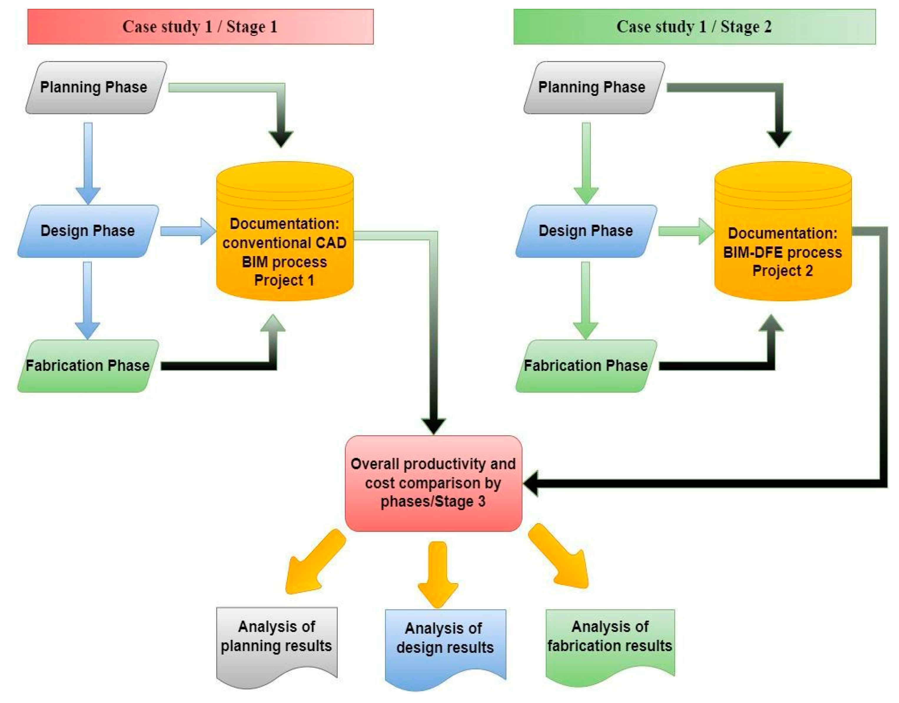
Given the current state of the steel construction industry and the significance of BIM in this context, the primary objective of this study is to conduct a comparative analysis between the traditional CAD-BIM methodology and the specific BIM-DFE methodology for steel construction. This comparative analysis is accomplished by applying both methodologies to two selected case studies and rigorously examining and comparing their respective quantitative productivity indicators across the critical phases of planning, design, and fabrication. These phases represent pivotal stages in which crucial decisions are made in steel construction projects. Through this in-depth comparative analysis, the study aims to evaluate the impact of the methodologies, providing valuable academic insights that can inform decision-making processes and contribute to the optimization of performance within the field of steel construction.
4. Discussion
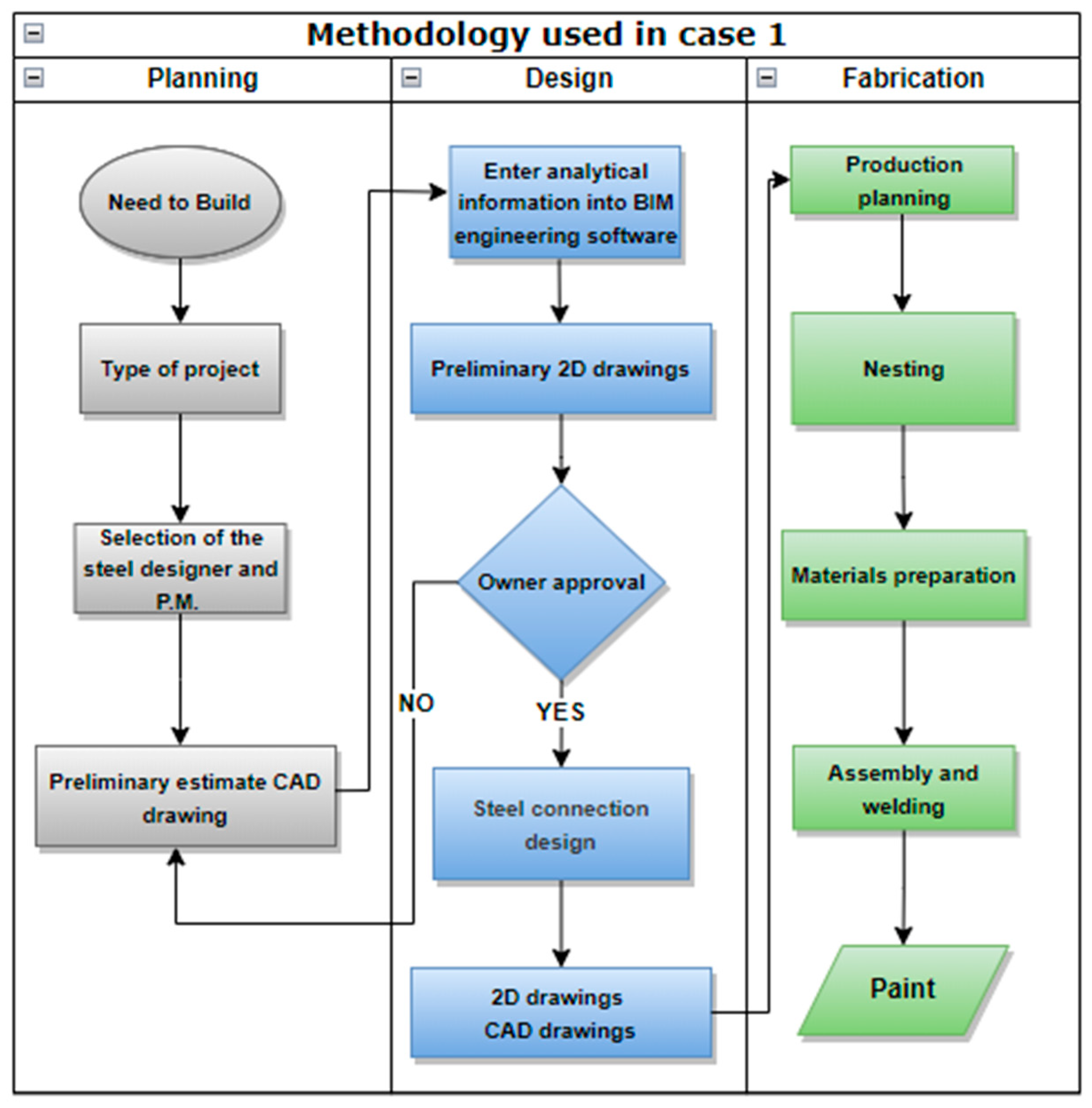
This section presents the results and implications of the two case studies. The first case study utilized the traditional CAD-BIM methodology for the planning, design, and fabrication of a steel construction project. The second case study applied the BIM-DFE methodology, which has been validated by experts in the industry and scientific community, but has not yet been applied in a practical case study.
This discussion presents a comparison between the productivity indicators of both case studies, an analysis of the advantages and limitations of each methodology, and the potential impact of the BIM-DFE methodology on the steel construction industry.
4.1. Planning Phase
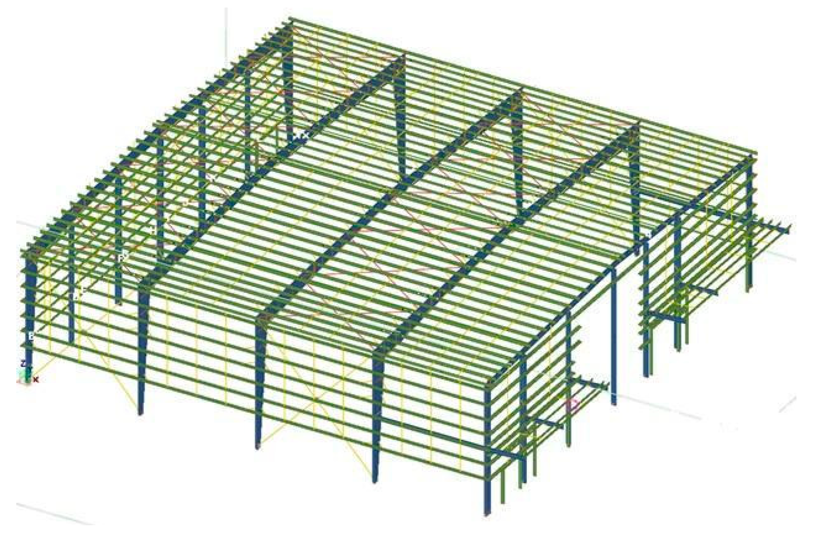
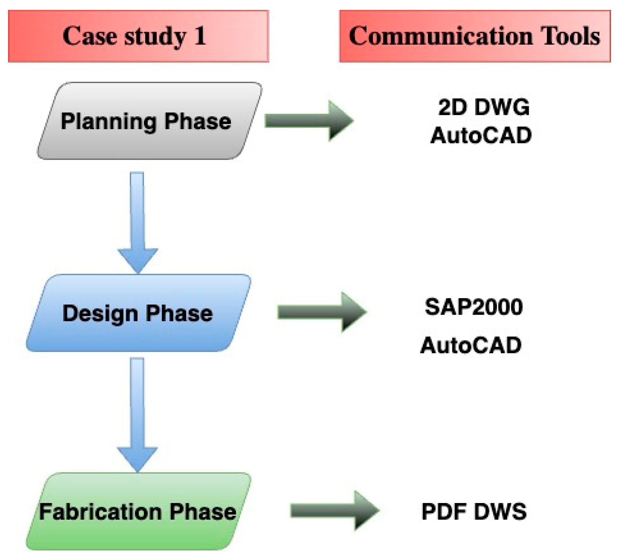
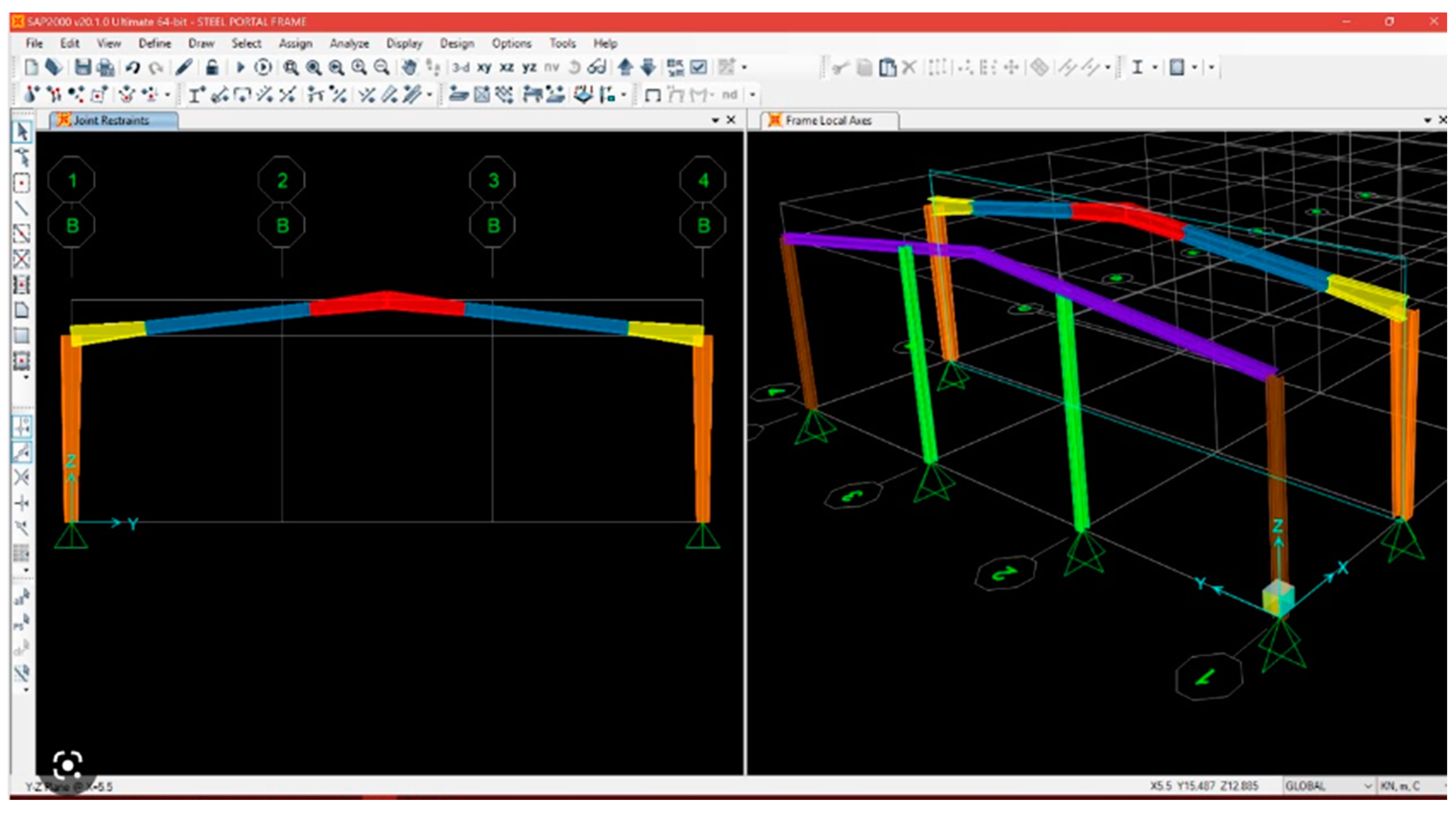
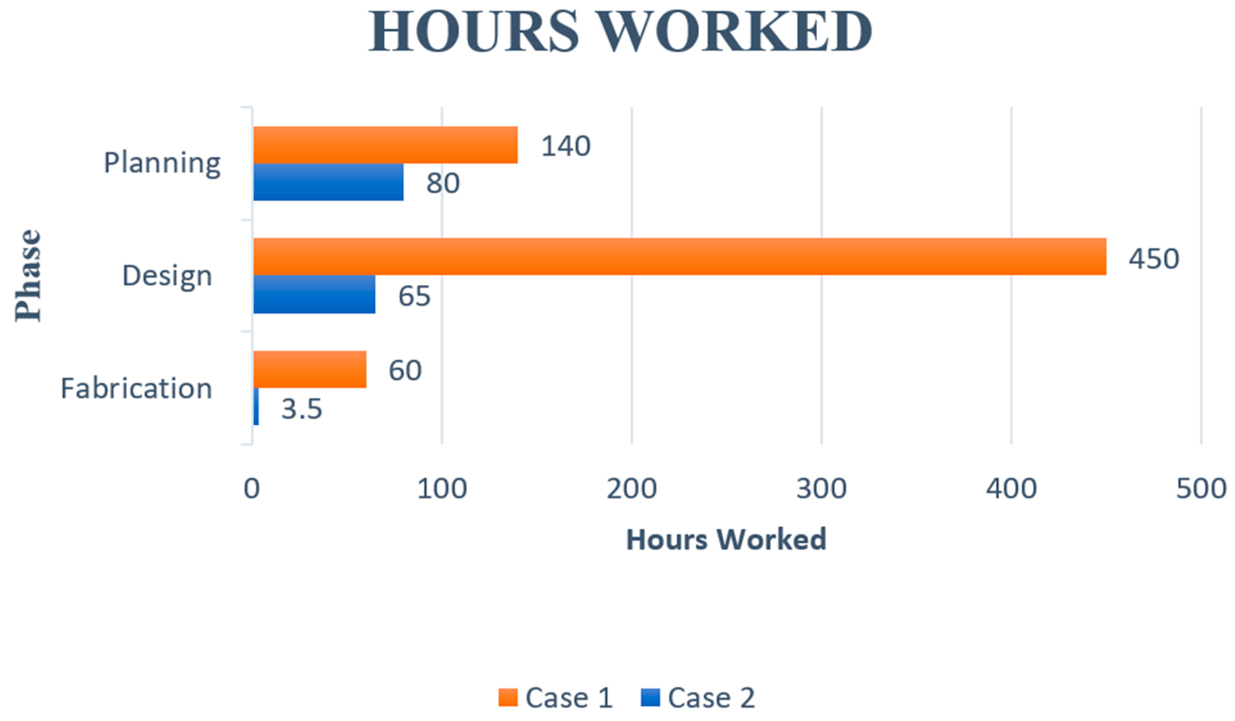
In case study 1, the traditional CAD-BIM methodology was used in the planning, design, and fabrication phases of a steel construction project, in which a total of 140 h was spent on planning: 60 h by the project manager/senior engineer and 80 h by a senior draftsman. The software tools used were AutoCAD and SAP2000. One disadvantage in this case was the use of two software tools that did not consider the transfer of nongraphical information between them, which slowed the planning process. Moreover, the presentation of 2D drawings to the client, who was not an expert in the construction industry, hindered their understanding of the project, which increased the period until the final design was approved.
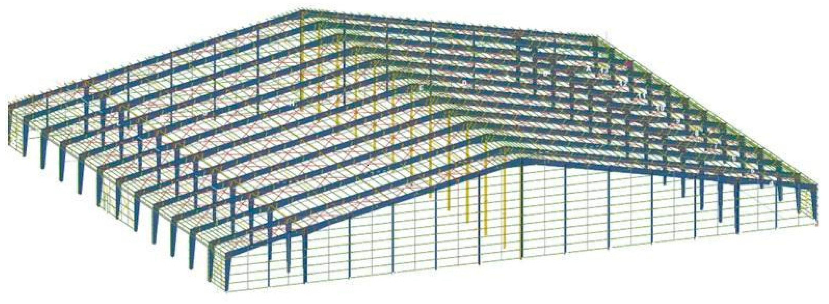
In contrast, in the planning phase of case study 2, BIM tools following the BIM-DFE methodology were used together with the software tools Tekla and SAP2000. The use of BIM in this phase helped the client understand the final design, which was presented in 3D, thereby accelerating the planning process. The transfer of information between the software tools was bidirectional in the IFC format, allowing interactions regardless of the geographic location because the model was shared in the Trimble Connect cloud of Tekla. The senior engineer spent a total of 40 h in the planning phase. The hours spent by the draftsman were not considered because the same engineer/project manager conducted both the modeling and verification following the client’s approval. It should be noted that while the project sizes were significantly different, the typology was the same. As the project in case study 1 was significantly smaller than that in case study 2, the total hours spent in case study 2 was considerably lower, indicating improved performance.
Note that the objective of planning in both cases was to determine the quantity of steel (in tons) that could be processed to estimate the costs. Therefore, it can be concluded that the use of BIM technology following the BIM-DFE methodology in case study 2 improved the performance in the planning phase compared with that in case study 1, which used traditional CAD-BIM methodology. The reduced number of the hours spent on planning in case study 2 highlights the efficiency and effectiveness of applying BIM technology in the construction industry.
The traditional CAD-BIM method in the planning phase suffers from the drawback of limited integration between BIM and non-BIM software (e.g., AutoCAD and SAP2000). This could slow the process owing to the need to manually transfer nongraphical information between different software platforms. In addition, 2D drawings are not as effective as 3D models in communicating the design intent to the owner, which can lead to delays in the approval process and potentially increase the number of hours required to complete the planning phase. Another disadvantage is that the traditional CAD-BIM method could require more specialized personnel, such as a senior project manager and draftsman, compared with the BIM-DFE method, which requires fewer personnel with more diverse skill sets.
4.2. Design Phase
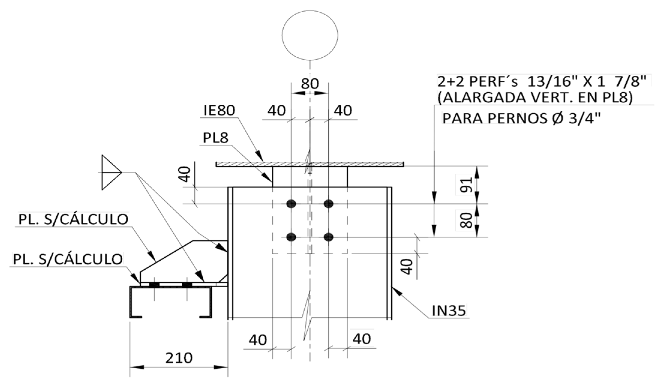
This study presents a comparison between two cases in the design phase of a construction project. In case study 1, the CAD-BIM utilized the traditional CAD method, in which the structural design was modeled in SAP engineering software and required 80 h from the senior engineer. After the analysis, a total of 100 h were spent on drawing: 60 h and 40 h by the senior and junior AutoCAD draftsman, respectively. The final design was disapproved by the client, and this required the engineer and senior AutoCAD draftsman to spend an additional 45 and 35 h, respectively, making necessary changes. This rejection was attributed to the client’s inability to understand the 2D plans, which prompted design changes. Finally, the senior engineer spent an additional 40 h calculating the connections, while the senior and junior draftsmen spent 50 and 40 h, respectively, representing the connections in 2D. An additional 60 h of drawing were required to complete the 2D deliverable in this phase.
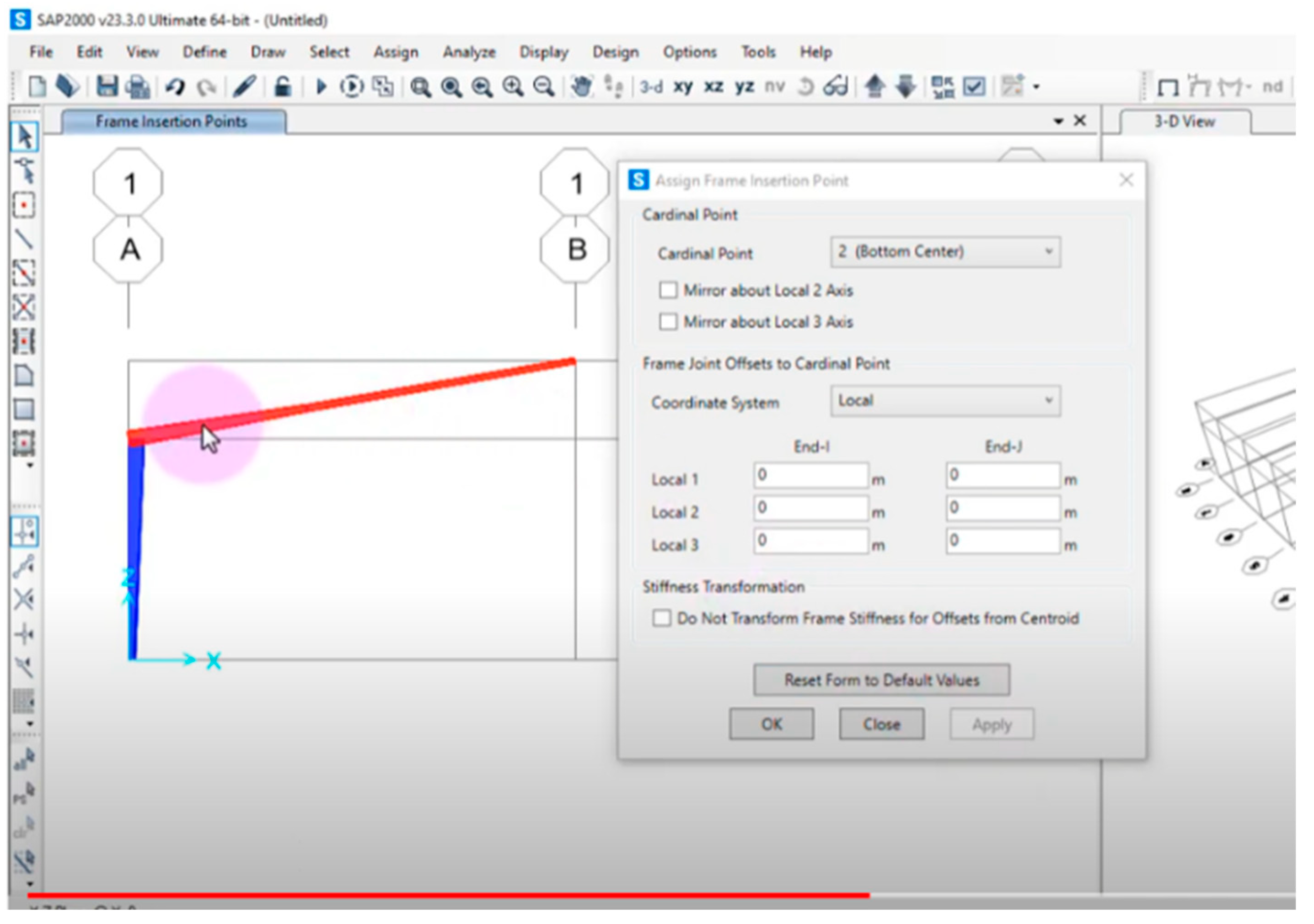
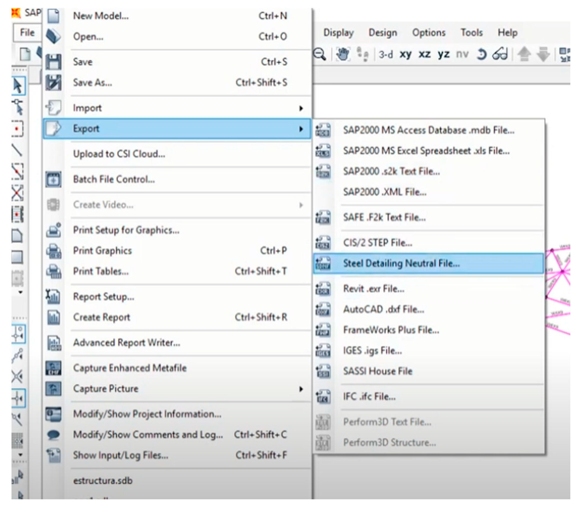
In case study 2, the implementation of BIM-DFE utilized a BIM estimation derived from the previous planning phase. This facilitated the efficient exchange of information in the IFC file format for seamless integration with the SAP2000 calculation software. This process required only 20 h from the senior engineer. The need for draftsmen was eliminated as the model was seamlessly transferred bidirectionally to Tekla, and then to Trimble Connect for client comprehension. The manufacturing plant constraints were seamlessly integrated at this stage, which required an additional 12 h of the engineer/project manager’s time and 8 h of the senior manufacturing manager’s time. This early communication fostered an enriched BIM, enabling the analysis of connections that required an additional 10 h of the senior engineer’s time. To ensure the feasibility of these connections, an additional 15 h of the senior engineer’s time were allocated for verification purposes.
A comparison of the two cases showed that the use of BIM in the design phase has several advantages over traditional CAD methods. BIM facilitates the transfer of information for a more efficient design process with fewer errors. The early incorporation of manufacturing constraints helps identify potential issues, saves time, and reduces the likelihood of expensive changes in the future. In addition, the BIM model improves the visualization and facilitates the client’s understanding of the design, thereby reducing the risk of design changes due to misunderstanding. Furthermore, apart from the proven advantages highlighted in the case study, it is crucial to recognize that there are numerous other established and valuable benefits associated with BIM. These encompass improved collaboration, optimized project scheduling, and enhanced facility management. These additional advantages greatly contribute to the overall value and efficacy of BIM in construction projects.
In contrast, the traditional CAD method required more time and resources in the design phase, as seen in case study 1. Design changes were extensive and required significant additional time from the senior engineer and AutoCAD draftsmen. In addition, the 2D plan format made it difficult for the client to understand the design, leading to further design changes.
Overall, the use of BIM-DFE in the design phase has clear benefits over the traditional CAD method. It facilitates a more efficient and effective design process, and reduces the likelihood of expensive changes and misunderstandings.
4.3. Fabrication Phase
We conducted an analysis of the advantages and disadvantages of employing a manual process for production planning in case study 1. In contrast, case study 2 utilized BIM technology for planning and detailed modeling, specifically emphasizing the prioritization of elements for fabrication.
4.3.1. Advantages and Disadvantages in Case Study 1
In case study 1, the production planning process required 40 h to manually extract information from the 2D drawing files. This manual process is prone to errors and could cause delays in the production process. In addition, the nesting process required 20 h and preparation 2.5 h/t of steel.
The assembly and welding subprocess required 9.5 h/t. The painting subprocess required 0.5 h/t, which is relatively fast but may be insufficient for large-scale projects.
4.3.2. Advantages and Disadvantages in Case Study 2
In case study 2, the production planning process required only 1 h because information from the previous stage was already available in the BIM model. Obtaining the details of the parts to be fabricated was significantly faster because of the automated process. The cleaning routines for the drawings were preconfigured in Tekla, which reduced errors and lead times.
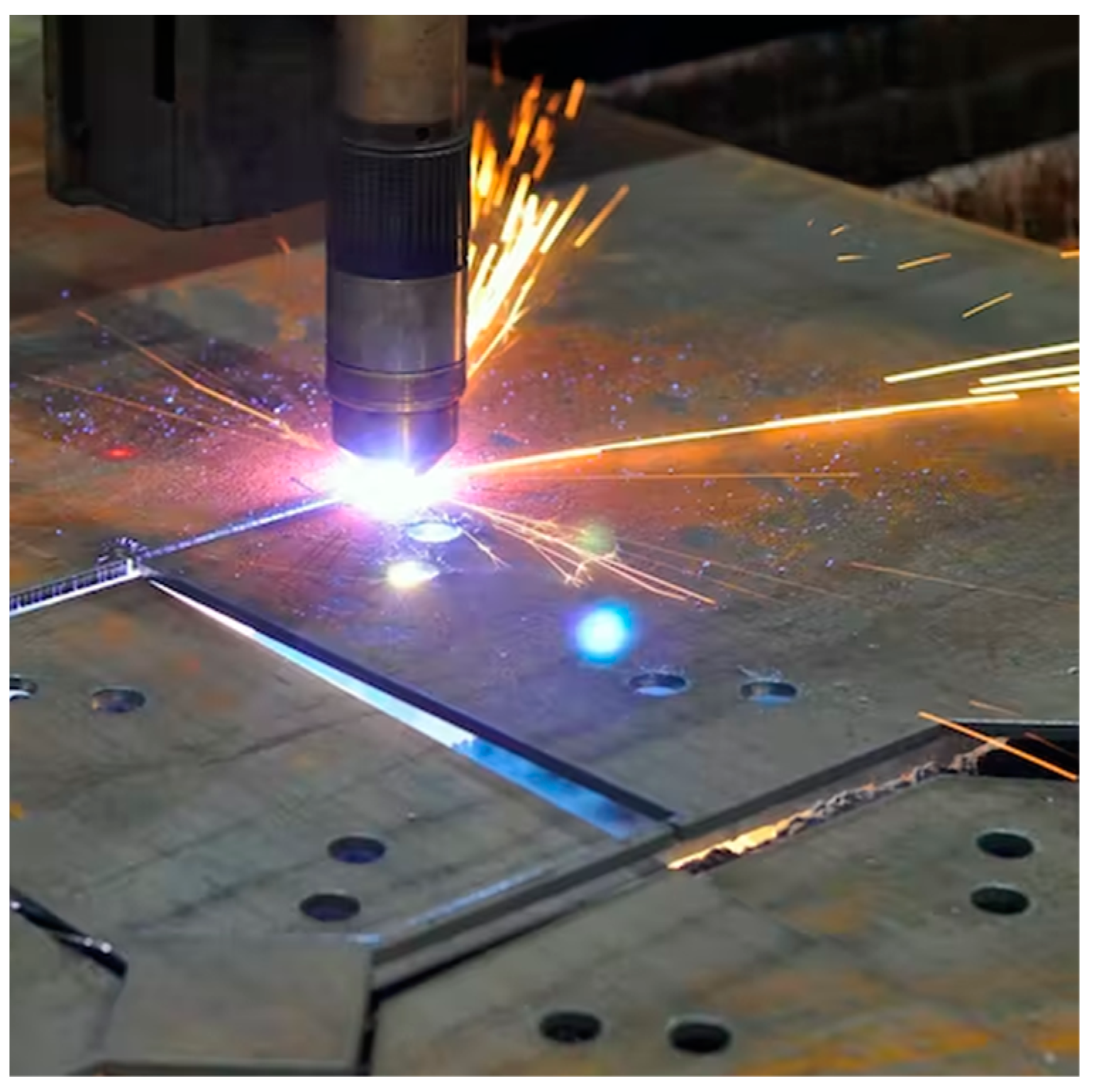
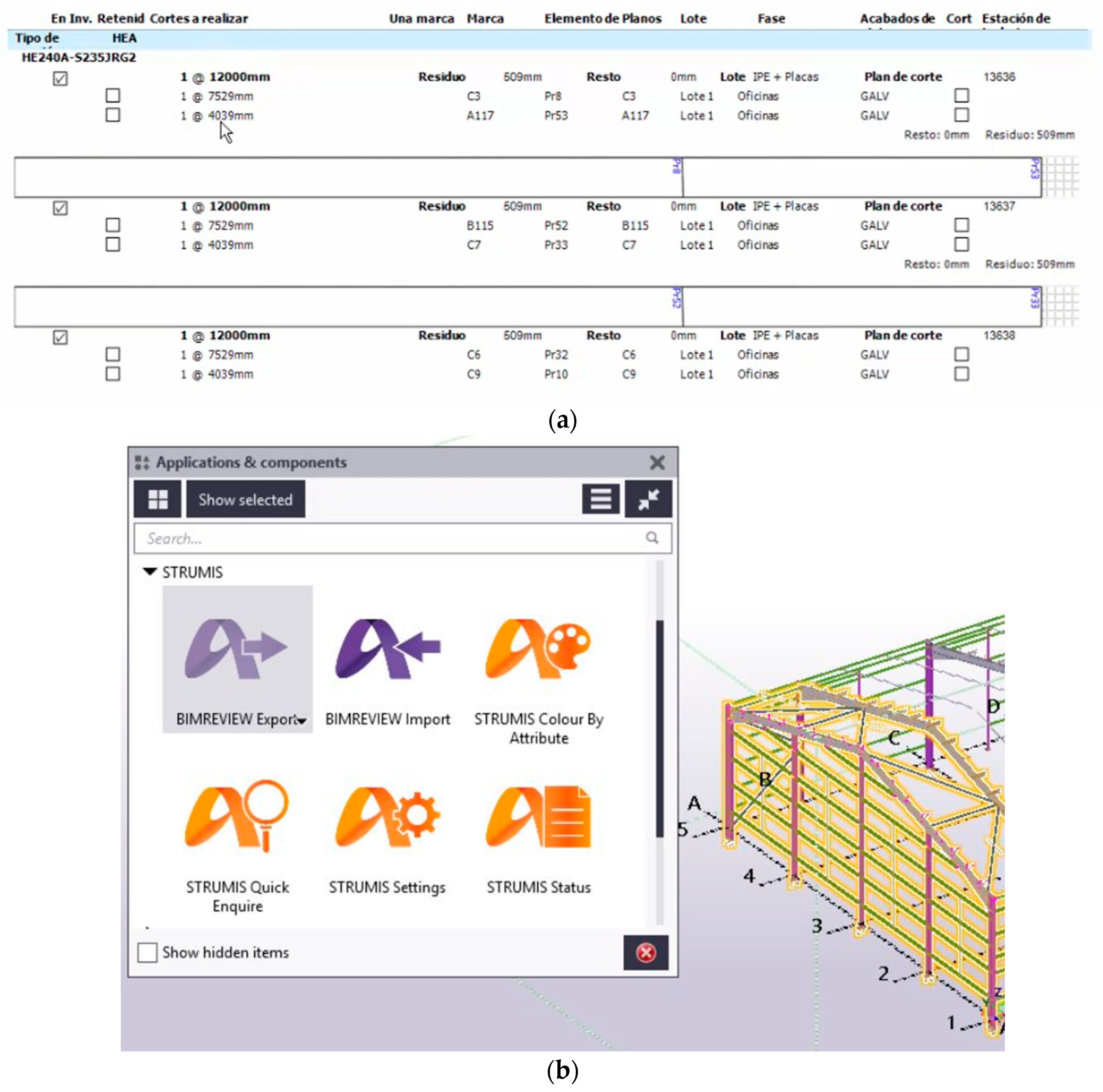
The information for nesting and production tracking was extracted in 2.5 h using tools such as Tekla and STRUMIS. Material preparation using a CNC plasma machine resulted in a productivity rate of 2.5 h/t, the same as that in case study 1. However, the assembly and welding subprocesses were significantly faster than those in case study 1, with a productivity rate of 7 h/t. This increase in productivity was attributed to the clarity of information presented in the 3D models, reducing the need for consultation with the fabrication manager and minimizing the need for the assembly and welding personnel to leave their workstations. The availability of information in the 3D model improved the organization of the workload. The painting subprocess had a productivity rate of 0.6 h/t, which is slightly better than that in case study 1. This was attributed to the size of Project 2 rather than the BIM-DFE.
Overall, the productivity indicator for case study 2 was 9.9 h/t. This is a reduction of 2.6 h/t and has a significantly positive impact on the manufacturing and construction durations of steel projects.
The use of BIM technology in the fabrication process offers several advantages over manual processing. Automated detailing, reduced errors, and increased clarity of information in the 3D model contribute to improved productivity. This improvement is particularly significant in critical subprocesses, such as assembly and welding. The use of BIM technology shortened lead times, reduced production costs, and increased customer satisfaction. However, the implementation of BIM-DFE requires investments in both software and personnel training.
BIM-DFE has proven to be a highly efficient methodology in the steel construction industry, as demonstrated by the case studies. BIM-DFE has the advantage of being specifically designed for steel construction by providing targeted solutions and optimizations for the unique challenges and requirements of this industry.
5. Conclusions
The analysis of the results of case studies 1 and 2 using the CAD-BIM and BIM-DFE methodologies, respectively, showed that BIM significantly improved the efficiency and productivity of the steel planning, design, and fabrication phases.
In case study 1, the manual extraction of information from 2D drawings extended the planning process, which led to longer processing times in the subsequent fabrication phase. In contrast, case study 2 exhibited notable improvements in planning and design, leading to a significant decrease in the duration of the fabrication phase, particularly the assembly and welding subprocesses. Case study 2 also demonstrated that the BIM-DFE methodology facilitated the automation of steel detailing by incorporating manufacturer constraints, resulting in a significant reduction in the time required for this process. BIM-DFE also reduced the need for human intervention, resulting in fewer errors and a more streamlined fabrication process.
The BIM-DFE methodology offers a more integrated approach, continuously enriching the model’s information from planning to fabrication, which ultimately results in a more efficient and effective process for all stakeholders. It can be concluded that the BIM-DFE methodology was not only validated by the literature and industry experts but also by its application to a real case in this study.
Among the limitations of this study is its focus on the planning, design, and fabrication phases of the project. Other phases, i.e., transportation and erection, were excluded owing to the timeline of the project.
Potential directions for future research related to this study include the following:
Evaluation of the impact of BIM-DFE on the construction, transport, and installation processes;
Exploration of the potential benefits of BIM-DFE in different types of construction projects, such as those using different materials or construction methods;
Development of new tools and workflows to enhance the integration of BIM and DFE methodologies, such as the integration of optimization algorithms and machine learning techniques.


