Abstract
So far, almost all studies have concentrated on the compressive performance of fully loaded concrete-filled double-skin steel tubular (CFDST) columns, but there have been few studies on partially loaded CFDST columns, and the difference in their behavior remains unclear. Thus, by focusing on the mechanical behavior of circular CFDST columns under different loading arrangements, this paper conducts a comparative study on circular axially loaded CFDST columns based on the author’s previous experimental results. A total of 28 experiments were conducted, in which 14 fully and 14 partially loaded specimens were tested. The influence law of crucial parameters on the compressive behavior of CFDST specimens with two different loading arrangements were compared and the results were discussed. It is shown that when the void ratio is 0 and 0.2, the ultimate strength of partially loaded CFDST columns is greater than that of fully loaded ones, but the results are opposite for the columns with the void ratios of 0.4 and 0.6. Subsequently, based on the experimental data, a finite element analysis (FEA) model was developed and used to ascertain the compressive behavior of CFDST columns with two different loading arrangements. The results suggested that, at the beginning of the loading phase, the outer tube of partially loaded CFDST columns provided a certain lateral confining stress to the concrete, while the lateral confining stress of fully loaded CFDST columns fluctuated around zero. The axial load of the inner tube of fully loaded CFDST columns first increased linearly and then remained almost unchanged. Due to the existence of friction, the inner tube of partially loaded CFDST columns also undertook a certain axial load, which first increased and then decreased to zero.
1. Introduction
As a member of steel and concrete composite structures, concrete-filled steel tubular (CFST) members are widely applied in high-rise buildings, gymnasiums, and bridge piers, by reason of their outstanding mechanical behavior, low cost of material, and short construction period [1,2,3,4]. In recent decades, high-rise buildings, large span, and heavy-duty structures have mushroomed, and a larger cross-section of column needs to be designed to meet the required load of the structures. As a result, this will lead to excessive loads imposed on the foundation, and be adverse to the seismic performance of the structures. For this reason, the concrete-filled double-skin steel tube (CFDST), as a branch of CFST family, has been developed. This is a relatively new type of composite structural element, in which concrete is infilled between two concentric steel tubes with different diameters [5,6,7,8]. Similar to conventional CFST columns, CFDST members possess the outstanding properties of having high strength and good ductility [9]. In addition, compared with CFST members, CFDST members are lighter, have greater flexural strength, better seismic resistance, and excellent fire resistance [10,11,12]. Therefore, CFDST members are suitable for a range of practical applications, such as bridge piers, sea-bed vessels, transmission towers, legs of offshore platforms, etc. [13], as shown in Figure 1.
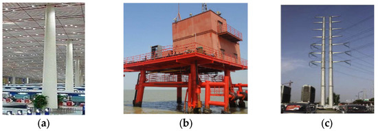
Figure 1.
CFDST columns in practical engineering. (a) Building structures. (b) Offshore infrastructures. (c) Tower structures.
To date, many researchers have investigated the mechanical behavior of CFDST members subjected to compression [14,15,16,17], flexure [18,19], torsion [20,21], and combined compression and bending [22,23], as well as during extreme events such as earthquakes and fire [24]. Herein, the mechanical behavior of CFDST members under axial loading is the research target of the current paper. To this end, the following literature review mainly focuses on the mechanical behavior of CFDST members under axial loading previously reported by many researchers. Han et al. [23] and Tao et al. [25], based on the experiments conducted, investigated the behavior of axially compressed CFDST columns with outer square (circular) and inner circular steel tubes, and developed the fiber element models for numerical simulations of columns. Uenaka et al. [26], Essopjee and Dundu [27], Ekmekyapar and Hasan [28], and Shi et al. [29] experimentally ascertained the effect of different column parameters on the mechanical behavior of circular CFDST columns under axial loading. Wang et al. [30] experimentally investigated the mechanical behavior of CFDST columns with outer stainless and inner carbon steel tubes under axial loading, and modifications to the current design provisions for CFST columns were proposed. Based on experimental tests, Yan et al. [31] investigated the confinement stress path of the concrete of CFDST columns, and suggested a simplified model for predicting the ultimate capacities of CFDST columns considering the effect of the confinement stress path. Hassanein et al. [10,11], Huang et al. [32], Li and Cai [33], Hu and Su [34], and Pagoulatou et al. [35] numerically investigated the impact of the critical variables on the strength and ductility of circular CFDST members under axial compression by using the ABAQUS software [36]. Based on the developed fiber element model, Liang [37,38], Ahmed et al. [39], Patel et al. [40], and Yan et al. [41] numerically discussed the variations of strength and ductility of CFDST columns subjected to axial compression as the key change parameters.
However, so far, almost all studies have concentrated on compressive performance of the fully loaded CFDST columns, and the study of the behavior of the partially loaded CFDST columns is very limited. For example, Yang et al. [42], by changing the thickness and compression area of the top end plate, experimentally investigated the behavior of partially loaded CFDST columns with outer square (or circular) and inner circular steel tubes. However, the mechanical behavior of the concrete section of axially loaded CFDST columns has not been discussed. In contrast to the loading arrangements of Yang et al. [42], Yan and Zhao [43] experimentally and numerically studied the behavior of circular concrete sections of axially loaded CFDST short columns, and suggested a strength prediction model. Because of different loading arrangements, the behavior of the partially loaded CFDST columns is different from that of the fully loaded columns, especially the bearing capacities of the steel tubes and concrete, which decides the bearing capacities of the columns. Further study is a necessary process towards a comprehensive understanding of the mechanical behavior of CFDST columns under different combined loading. However, thus far, the difference in their behavior remains unclear, and has not been covered in the published literature. To this end, further comparative study on the behavior of the axially fully and partially loaded CFDST columns needs to be put on the agenda.
To address this concern, this paper conducts a comparative study on circular axially loaded CFDST columns under different loading arrangements based on the authors’ previous experimental results. A total of 28 experiments were conducted, and 14 fully and 14 partially loaded specimens were previously tested. The effects of various parameters on the compressive behavior of CFDST specimens with two different loading arrangements are compared and the results are discussed. Subsequently, a finite element analysis (FEA) model was developed and validated through a comparison with the conducted experiments. Finally, utilizing the validated FEA model, the mechanical behavior of CFDST columns under two different loading arrangements is compared. The typical curves of axial load versus axial strain, the interaction between steel tubes and concrete, and the longitudinal stress distribution of concrete sections are discussed, before the paper concludes with the key observations from this study.
2. Review of Experimental Program
2.1. Test Specimens
A part of the CFDST specimens from the two papers previously published by the authors of [31,43], as shown in Table A1 in Appendix A, were taken for comparison, which has not been carried out before. A total of 28 specimens were tested to determine the mechanical behavior of CFDST short columns under different loading arrangements. The tested specimens consist of 14 circular, fully loaded (both steel tube and concrete cross-sections were loaded simultaneously) and 14 partially loaded (only the concrete cross-section was loaded) CFDST columns. The investigated parameters include the void ratio (χ), yield strength (fsyo), and wall thickness (to) of the outer steel tube, and concrete strength (fc). It was found that different void ratios were applied in the two published papers, mainly due to the use of different definitions of void ratios. It is noteworthy that, in this work, χ is determined by χ = Di/(Do-2to), which is consistent with the definition of the void ratio in Reference [43]. Do and to are the outside diameter and wall thickness of the external tube, respectively; Di and ti are the outside diameter and wall thickness of the internal tube, respectively.
In the previous paper, the outer or inner steel tubes of the CFDST specimens adopted two types and six different geometric dimensions of circular hollow steel tubes; see Figure 2. The material properties of the steel tubes are shown in Table A2 in Appendix A. In the table, STK400 and STK490 represent the different steel types [44]; fsy and fsy denote the yield strength and ultimate strength of steel, respectively; Es denotes the elastic modulus of steel; δ represents the steel elongation. In addition, as shown in Table A1, the wall thicknesses of the outer steel tube are 4.3, 5.3, and 6.8 mm, respectively. The diameter-to-thickness ratio of the outer steel tube varies with changes in its wall thickness (keeping the diameter of the outer steel tube as a constant). The values of the void ratio are 0, 0.2, 0.4, and 0.6, respectively, and the corresponding cross-sectional dimensions of the internal tube are 34 × 3.2 mm, 60.5 × 3.8 mm, and 101.6 × 4.2 mm, respectively. According to the commercial concrete mixing scheme of Marucrystal Industrial Co., LTD., in Japan, the grades of concrete strength in this study were designed as C24, C36, and C48, respectively, and the corresponding standard concrete cylinder strength values are 29 MPa, 38 MPa, and 51 MPa, respectively. The height of all CFDST specimens was designed to be three times the diameter of outer steel tube, i.e., 573 mm.
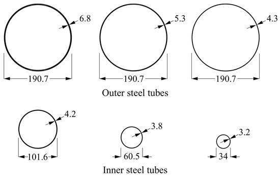
Figure 2.
Cross-sectional form of steel tubes in CFDST columns.
2.2. Column Testing Process
All the experiments on the CFDST columns were conducted in the Architectural and Structural Engineering Laboratory, Kanagawa University, in Japan. In order to observe the strain changes in the longitudinal and circumferential directions of the steel tubes during the loading process, a total of 8 strain rosettes were uniformly arranged in the circumferential direction along the middle section of the inner and outer steel tubes; the average value of the two strains at the symmetrical position was taken. Two LVDTs were symmetrically arranged to monitor the axial deformation of columns during the loading process. The specific arrangements of strain rosettes and LVDTs are shown in Figure 3.
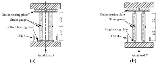
Figure 3.
Layout of strain rosettes and extensometer. (a) Full section. (b) Concrete section.
In addition, the layout diagram of loading device of the studied CFDST specimens are presented in Figure 3 and Figure 4. From these two figures, it can be found that different loading arrangements were achieved by changing the form of the rigid plate adjacent to the specimens. The outlet rigid plate located above the specimens was mainly used to transfer axial load and output the data collection wire of the strain rosettes pasted on the inner steel tube. An electro-hydraulic servo compression shear testing machine provided with the axial loading capability of 5000 kN was employed for all the CFDST columns. The displacement control manner with a loading rate of 0.04 mm/s was used to apply the load, and the loading was ended when the specimen was damaged or the post-peak load decreased to 85% of the ultimate load.
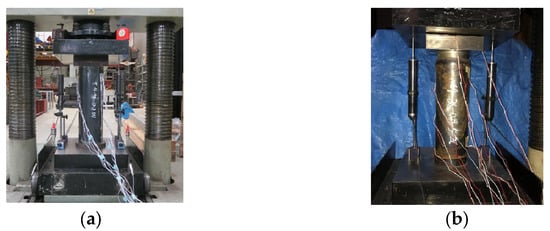
Figure 4.
Loading device for CFDST columns. (a) Full section. (b) Concrete section.
3. Comparisons of Experimental Results
3.1. Failure Modes
After the termination of the experiments, the CFDST columns suffered a certain degree of damage. As shown in Figure 5, the two typical specimens, e.g., C4-36-0.18-5WL-1 and C4-36-0.19-1C, were selected to discuss the failure patterns of the CFDST columns under different loading arrangements. From this figure, it can be observed that due to different loading arrangements, the failure patterns of the CFDST columns show an evident difference. Firstly, by comparing the failure pattern of the external tube, different bulging failures are found at the upper and lower ends and middle sections of the fully loaded CFDST columns. However, the outward bulging failure occurred in the middle of the partially loaded CFDST columns, and the bulging range is larger than that of fully loaded ones. Secondly, compared with the failure modes of the inner steel tubes, a certain degree of inward bulging occurred in the middle part of the inner steel tube of the fully loaded CFDST columns. The main reason is that the inner steel tube carried a certain axial load and the sandwiched concrete was crushed and extruded. However, there is almost no change in the inner steel tube of the partially loaded CFDST columns. This is mainly because the sandwiched concrete mainly bore axial loads, even if a portion of the force was shifted to the inner steel tube because of friction, which is not sufficient to cause obvious deformation.
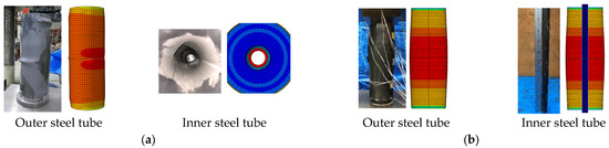
Figure 5.
Comparisons of predicted and observed typical failure modes of CFDST specimens. (a) C4-36-0.18-5WL-1 (full section). (b) C4-36-0.19-1C (concrete section).
3.2. Axial Load versus Axial Strain Curves
Figure 6 and Figure 7 show the visual contrast of axial load versus strain curves of CFDST columns with different loading arrangements. The specimens in S1 (Series 1) and S2 (Series 2) with different yielding stress of the outer tube and void ratio are taken as examples. S1-F0, as an example, denotes the fully loaded CFDST specimens with a hollow ratio of 0 in Series 1. With reference to Figure 6 and Figure 7, it can be observed that, at the beginning of the loading phase, the axial force of the CFDST specimens with void ratios of 0 and 0.2 under different loading arrangements increased as the axial strain increased. Afterwards, as the axial strain continued to increase, the axial load of the fully loaded CFDST columns was greater than that of the partially loaded ones. While the axial strain increased to around 0.007, the axial force of the partially loaded CFDST specimens was greater than that of the fully loaded ones until the specimen was damaged or the post-peak load decreased to 85% of the ultimate strength. This is attributed to the fact that at this point, the confinement effect of the outer and inner steel tubes of the partially loaded CFDST columns was stronger than that of the fully loaded ones.
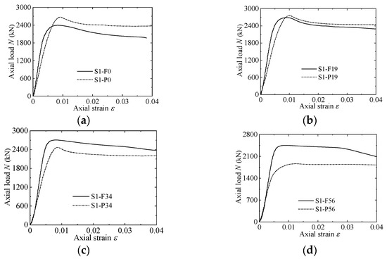
Figure 6.
Comparisons of the axial load vs. axial strain of fully and partially loaded specimens in S1.
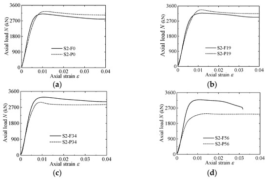
Figure 7.
Comparisons of the axial load vs. axial strain of fully and partially loaded specimens in S2.
In addition, with reference to Figure 6 and Figure 7, it can be observed that, at the beginning of the loading phase, the axial force of the CFDST specimens with void ratios of 0.4 and 0.6 under different loading arrangements is almost the same as the axial strain increased. Subsequently, as the axial strain increased to around 0.003, the axial force of the fully loaded CFDST specimens became greater than that of the partially loaded ones. This phenomenon persisted until the end of loading. This is mainly because, as the void ratio increased, the confining stress to the concrete infill generated by the outside and inside tubes of the partially loaded CFDST specimens reduces. This results in the axial load of the partially loaded CFDST specimens always being smaller than that of the fully loaded ones.
3.3. Ultimate Capacities
The comparisons of the ultimate load values of the fully and partially loaded CFDST specimens are presented in Figure 8. In Figure 8a, it is observed that the ultimate load of CFDST specimens under different loading arrangements first increases and then decreases as the void ratio improves. When the void ratio is 0 and 0.2, the ultimate load of the partially loaded CFDST columns is greater than that of the fully loaded ones, but the results are opposite for the specimens with void ratios of 0.4 and 0.6. This indicates that the lateral restraint action generated by outer and inner steel tubes to the concrete infill was gradually weakened as the void ratio increased. As a result, the strength improvement of the confined concrete of the partially loaded CFDST columns decreased, resulting in a lower ultimate strength (whole cross-sectional strength) than that of the fully loaded CFDST columns. With reference to Figure 8b, the ultimate load of CFDST specimens under different loading arrangements increased with improvement of the concrete strength. The ultimate load of the fully loaded CFDST specimens with void ratio of 0.4 is greater than that of the partially loaded ones. From Figure 8c, it can be observed that the ultimate load of CFDST columns under different loading arrangements decreased as the diameter-to-wall thickness of outer steel tube was improved. This is mainly because the increase in the diameter-to-wall thickness ratio leads to a reduction in the steel ratio of the CFDST specimen. As a result, this weakens the confinement effect given by the steel tube to the concrete infill, thereby lowering the ultimate load of the specimen.
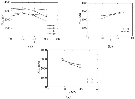
Figure 8.
Comparisons of the ultimate strengths between fully and partially loaded specimens. (a) Hollow ratio. (b) Concrete strength. (c) Diameter-to-thickness ratio of outer steel tube.
4. Establishment and Verification of FEA Model
4.1. Establishment of FEA Model
In this section, the commercial analysis software ABAQUS (2008) is employed to develop the FEA models of CFDST columns under different loading arrangements. The reliability and accuracy of the developed FEA models are verified using available experimental results, which include the axial load versus axial strain curves, ultimate load, and failure modes. The FE model of partially loaded CFDST columns has been verified by the authors of Reference [43]. Thus, the FE model of fully loaded CFDST columns needs to be validated and the specific details are as follows.
4.1.1. Stress versus Strain Constitutive Relation of Carbon Steel
An ideal multilinear stress vs. strain constitutive relation given by Han et al. [45] is applied herein to simulate steel, as illustrated in Figure 9. This model was frequently adopted by many foreign and domestic scholars, e.g., Yan et al. [7], Huang et al. [32], Li and Cai [33], and Wang et al. [30], etc. Hence, the steel constitutive relation presented by Han et al. is as follows:
in which Es and fsy represent the modulus of elasticity and yield strength of the steel used, respectively, and Es is equal to 2.0 × 10⁵ MPa; A = 0.2fsy/(ε2 – ε1)2, B = 0.2Aε2, C = 0.8fsy + Aε12 – Bε1, ε1 = 0.8fsy/Es, ε2 = 1.5ε1, ε3 = 10ε2, ε4 = 100ε2.
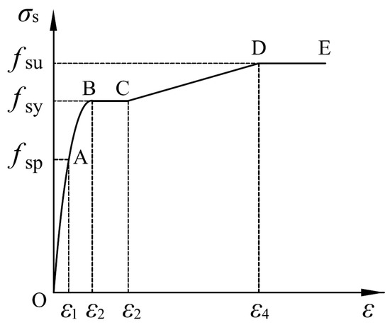
Figure 9.
Stress (σ)–strain (ε) relationship for steel.
It is noteworthy that the engineering stress versus strain constitutive relation of steel needs to be converted into the real stress versus strain constitutive relation, which is then input into the sub-interface of the material in the FEA model. The conversion formulas are as follows:
in which and are the engineering stress and strain obtained from the tests of material properties, respectively; and are the actual stress and strain, respectively.
4.1.2. Stress versus Strain Constitutive Relation of Concrete
The stress versus strain constitutive relation of concrete proposed by Han et al. [45] achieved excellent performance in the simulation of CFST columns or CDDST columns under different loading conditions, such as compression, flexure, and combined compression and bending [17,18,19,20,21,22,23]. Therefore, in this current paper, the stress vs. strain constitutive relation of concrete proposed by Han et al. [45] is employed and determined by
in which x = ε/ε0, y = f/fc, f represents the axial stress of concrete when the axial strain reaches ε; fc represent the cylinder concrete strength, and the corresponding strain is ε0; η and β0 are the parameters that depend on the form of column cross-section. η is equal to 2 for the circular cross-section, and the corresponding parameter β0 is determined by
in which ξ denotes the confinement coefficient.
Additionally, the damaged plasticity model of concrete has been adopted in the current paper, and the detailed information of the CDP model has been presented in the literature [7,32,46]. According to ACI 318-19 [47], the elastic modulus and Poisson’s ratio of concrete are taken as Ec = 4730(fc)0.5 and μc = 0.2, respectively.
4.1.3. Loading and Boundary Conditions, Element Mesh
The concrete infill and steel tube of the studied members were modelled using the solid element with eight-node reduced integration (C3D8R) and a shell element with four nodes (S4R) [7]. According to the convergence analysis of the mesh element, the element size of the cross-section was taken as Do/20. For the boundary conditions, except for the longitudinal translation of top surfaces, all degrees of freedom of the two ends of fully loaded CFDST columns were constrained. Instead of directly loading, a uniform displacement was imposed on the top surface of the column.
4.1.4. Contact Modeling
A general surface contact model was employed to simulate the contact behavior between the concrete and steel tube [32,33]. A hard-contact relationship was used in the tangent direction, where the contact element transmits interface pressure, and the pressure perpendicular to the contact surface can be completely transmitted between interfaces. A “penalty function” with a friction coefficient of 0.6 was used to define the contact relationship in the tangent direction. In addition, in order to improve convergence, the internal surface of the outer steel tube as well as the external surface of inner tube were designated as the primary surfaces, respectively, while the outside and inside of the sandwiched concrete were simultaneously assigned as the secondary surfaces.
4.2. Establishment of FEA Model
The rationality and accuracy of the developed FEA model were verified on the basis of the conducted experimental data on the performance of fully loaded CFDST short columns. The measured axial load versus axial strain curves, ultimate capacities, and failure modes for various tests and numerical simulations are compared and discussed.
4.2.1. Axial Load versus Axial Strain Curves and Ultimate Capacities
Figure 10 presents comparisons of the axial load versus axial strain responses for CFDST specimens, together with the corresponding numerical simulations. From Figure 10, it can be observed that the developed FEA model can effectively replicate the axial load versus axial strain responses of the specimens. However, the axial load versus axial strain curves obtained from the experiments are slightly different from the numerical results. This difference may be due to the incomplete agreement between the numerical simulation of the interaction between steel tubes and concrete and the actual experimental conditions. In addition, due to the different curing methods, the actual concrete strength in the CFDST columns may also differ from that obtained from the standard concrete property tests.
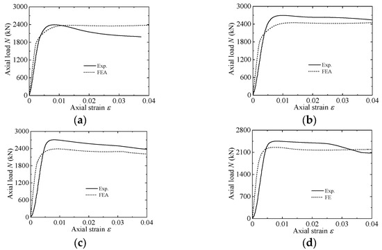
Figure 10.
Verification of axial load vs. strain curves of fully loaded specimens. (a) C4-36-0-5WL-1/2. (b) C4-36-0.18-5WL-1/2. (c) C4-36-0.31-5WL-1/2. (d) C4-36-0.53-5WL-1/2.
For further validation, the comparison between the numerical simulations and the experimental strengths are presented in Figure 11. With reference to Figure 11, it can be observed that the ultimate capacities predicted by the developed FEA model are a good approximation to the experimental values of fully loaded CFDST specimens. Overall, it is shown that the developed FEA model can accurately predict the ultimate capacities of fully loaded CFDST short columns.
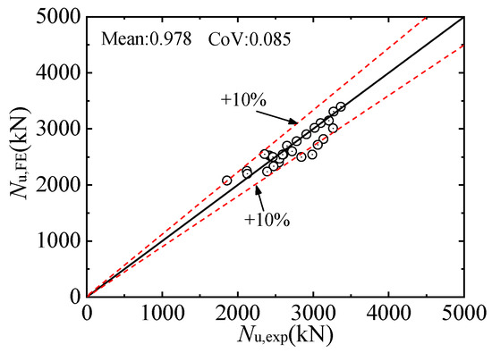
Figure 11.
Comparison of experimental strengths and numerical simulations.
4.2.2. Failure Mode
Moreover, the comparison between the failure modes from the experimental tests and the developed FEA model are given in Figure 5. In this figure, the typical failure modes of the outer and inner steel tubes of the CFDST specimens, e.g., C4-36-0.18-5WL-1 and C4-36-0.19-1C, were selected as examples and compared. With reference to Figure 5, it can be noticed that the developed FEA model for CFDST short specimens under different loading arrangements can replicate the failure modes of the outer and inner steel tubes of the experimental tests very well.
Generally, based on Reference [43] and the verification of this section, it is concluded that the developed FEA model can generate an accurate depiction of the overall performance analysis and failure modes of the investigated CFDST members. As a result, in the next section, the developed FEA model is employed to conduct the mechanism analysis of the CFDST columns under different loading arrangements.
5. Mechanism Analysis
By employing the verified FEA model, the axial load distribution, the lateral confinement stress, and the longitudinal stress distribution of the concrete infill of CFDST columns under different loading arrangements were analyzed and compared. The investigated parameters are given as: Do × to = 300 mm × 8 mm, Di × ti = 140 mm × 5 mm, fsyo = fsyi = 275 MPa, fc = 50 MPa, L = 900 mm, χ = 0.5.
5.1. Axial Load Distribution
Figure 12 shows the axial load distribution of each component of circular fully and partially loaded CFDST short columns. In Figure 12, Nu represents the ultimate capacity of the column; Nuc, Nuo, and Nui denote the ultimate capacities of the sandwiched concrete, external, and internal steel tubes of CFDST columns under different loading arrangements, respectively. With reference to Figure 12, it can be concluded that, with the improvement in axial strain, the axial load of the fully and partially loaded CFDST columns is first improved and then is reduced, and eventually tends to a constant. The axial load of the fully loaded CFDST columns is larger than that of the partially loaded ones. In addition, the axial strains of the elastic limit, the elastic–plastic limit, and the ultimate axial load of the fully loaded CFDST columns are 0.78 × 10⁻³, 1.46 × 10⁻³, and 5.5 × 10⁻³, respectively, which are smaller than those of the partially loaded CFDST columns. The key reason is that, at these points, the improvement in strength of the partially loaded columns induced by the constraint effect is greater than the cross-sectional strength provided by the outer and inner steel tubes of the fully loaded ones.
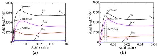
Figure 12.
Load distribution of each component of fully and partially loaded CFDST columns. (a) Full section. (b) Concrete section.
A similar conclusion is also found for axial load of the sandwiched concrete of CFDST columns under different loading arrangements. From Figure 12a,b, it can be found that the axial load of the sandwiched concrete of CFDST columns under different loading arrangements had not yet reached the maximum value when the ultimate capacity of the column was reached. This is mainly because, at this point, the confinement effect provided by the outer and inner steel tubes to the concrete still has a positive effect on the cracking behavior of the sandwich concrete.
In addition, the axial force distribution of the outer and inner steel tubes of CFDST columns under different loading arrangements is also discussed. As shown in Figure 12a,b, the axial force of the external tube of CFDST columns under different loading arrangements first increased and then decreased. When the axial strain reached around 0.01, the axial force of the outer steel tube reached the minimum value. Then, as the axial strain continued to increase, the axial force borne by the outer steel tube increased. This is mainly attributed to the strain hardening of the external tube. In addition, with reference to Figure 12a,b, the axial force of the inner steel tube of the fully loaded CFDST columns first increased linearly and then kept almost constant. Because of the inevitable friction, referring to the above tests, the inner steel tube of the partially loaded CFDST columns also undertook a certain axial force that first increased and then decreased to zero. The main reason for the decrease in axial force is that when the axial strain increases to a certain extent, the effective Poisson’s ratio of concrete exceeds that of the steel tube, resulting in the surface separation between the internal steel tube and the concrete.
5.2. Interaction between Steel Tube and Concrete
Figure 13 and Figure 14 present the lateral confining stresses of the outer and inner steel tubes to the concrete in the fully and partially loaded CFDST columns. In Figure 13 and Figure 14, pso and psi represent the lateral confining stresses of the outer and inner steel tubes to the concrete, respectively. With reference to Figure 13, it can be observed that, in the initial loading stage, the lateral confining stress of the outer steel tube to the concrete in the fully loaded CFDST columns is almost equal to zero, while the inner steel tube gives a certain lateral restraint stress. This is mainly because the Poisson’s ratio of steel tube outweighs that of the concrete infill. As the axial strain continues to increase, the effective Poisson’s ratio of infilled concrete starts to outweigh that of steel tube. Consequently, the lateral confining stress of the outer steel tube begins to appear and gradually increase, and finally approaches a constant (about 7.2 MPa). On the contrary, the lateral confining stress of the inner steel tube begins to decrease and eventually fluctuates around zero. As shown in Figure 14, it can be observed that, unlike the fully loaded CFDST columns, in the initial loading stage, the outer steel tube of the partially loaded CFDST columns provides the lateral confining stress to the concrete infill. This is mainly because, at the beginning of loading phase, the Poisson’s ratio of the outer steel tube is already smaller than the effective Poisson’s ratio of the sandwiched concrete of the fully loaded CFDST columns. With the increasing axial strain, the lateral confining stress of the outer steel tube increases gradually, and finally approaches a constant (about 15.0 MPa). The change trend in the lateral confining stress generated from the inner steel tube of the partially loaded CFDST columns is similar to that of the fully loaded ones. Obviously, the lateral confining stress of the outer steel tube to the concrete in the fully loaded CFDST columns is less than the that of the partially loaded ones.
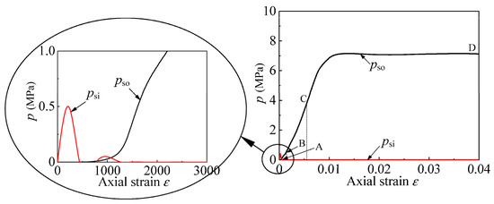
Figure 13.
Lateral confining stress of fully loaded CFDST columns.
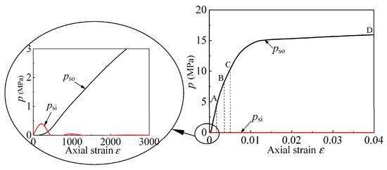
Figure 14.
Lateral confining stress of partially loaded CFDST columns.
5.3. Longitudinal Stress Distribution across Concrete Section
The longitudinal stress distribution of the sandwiched concrete of the fully and partially loaded CFDST columns is depicted in Figure 15 and Figure 16. Corresponding to the axial load versus axial strain curves discussed above, the longitudinal stress distribution of the sandwiched concrete at four key points of the axial load versus axial strain curves of the CFDST columns under different loading arrangements was analyzed and compared. As shown in Figure 12, points A, B, C, and D represent the different stages of the loading process of CFDST columns. For example, points A, B, C, and D represent the elastic limit, elastic–plastic limit, ultimate axial load, and loading termination of the axial load versus axial strain curves of the CFDST columns. With reference to Figure 15 and Figure 16, it can be observed that the longitudinal stresses of the sandwiched concrete at points A, B, C, and D in the partially loaded CFDST columns are larger than those of the sandwiched concrete of the fully loaded ones except for the edge concrete stress at point D. This is principally because the lateral confining stress generated by the outside and inside steel tubes of the partially loaded CFDST columns to the sandwiched concrete is larger than that of the fully loaded ones. In addition, it is also shown that the longitudinal stress of the concrete first increases and then decreases from the inner surface to the outer surface of the sandwiched concrete. The key reason is that the change in the confining stress provided by the steel tubes to the concrete results in the stress of the surfaces of the sandwiched concrete being between the biaxial stress state and the triaxial stress state.
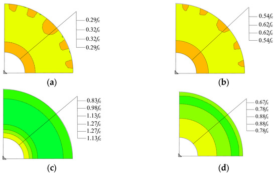
Figure 15.
Longitudinal stress distribution of fully loaded CFDST columns. (a) Point A. (b) Point B. (c) Point C. (d) Point D.
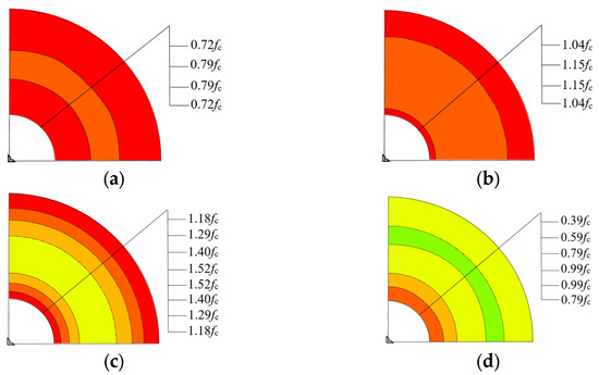
Figure 16.
Longitudinal stress distribution of partially loaded columns. (a) Point A. (b) Point B. (c) Point C. (d) Point D.
6. Conclusions
The experiments of 28 circular CFDST columns, including 14 fully loaded and 14 partially loaded specimens, were carried out. The effects of various parameters on the compressive behavior of CFDST columns with two different loading arrangements were investigated and compared. The established FEA model was validated against the conducted experimental data. Utilizing the validated FEA model, the mechanical behavior of CFDST columns with two different loading arrangements were discussed. Based on the research presented, the following conclusions are given:
- (1)
- The various bulging failure modes were discovered at the upper and lower ends and middle sections of the fully loaded CFDST columns. However, the outer bulging failure occurred in the middle of the partially loaded CFDST columns, and the bulging range is larger than that of the fully loaded ones. In addition, a certain degree of inward bulging occurred in the middle part of the internal steel tube of the fully loaded CFDST columns. However, there is almost no change in the inner steel tube of the partially loaded CFDST columns.
- (2)
- The ultimate capacity of the partially loaded CFDST specimens with the void ratios of 0 and 0.2 is greater than that of the fully loaded ones, while the conclusions are just the opposite for the specimens with the void ratios of 0.4 and 0.6. In addition, the ultimate capacity of CFDST specimens increases as the concrete strength increases, and decreases as the tube diameter-to-wall thickness ratio of outside tube enhances.
- (3)
- The developed FEA model can provide an accurate depiction of the overall performance analysis and failure patterns of the CFDST specimens, and can be employed to conduct the mechanism analysis of the CFDST columns under different loading arrangements.
- (4)
- The axial load of the outer steel tube of CFDST columns under different loading arrangements first increased and then decreased. When the axial strain reached around 0.01, the axial force of outer steel tube reached the minimum value. Then, as the axial strain continued to increase, the axial force borne by the outer steel tube increased. This is principally due to the strain hardening of the outer steel tube.
- (5)
- The axial load of the inner steel tube of the fully loaded CFDST columns first increased linearly and then kept almost constant. Because of the inevitable friction, the inner steel tube of the partially loaded CFDST columns also bore a certain axial load that first increased and then decreased to zero.
- (6)
- Due to different loading arrangements, during the initial loading stage, a certain restraint stress generated by the outer steel tube of the partially loaded CFDST columns was imposed on the concrete, but the confining stress of the fully loaded ones was almost zero.
- (7)
- The longitudinal stress of the concrete infill in the different loading stages of the partially loaded CFDST columns was larger than those of the fully loaded ones except for the edge concrete stress at the loading termination point. The main reason is that the confining stress generated by the steel tubes of the partially loaded CFDST columns to the concrete was larger than that of the fully loaded ones.
Author Contributions
X.-F.Y.: Conceptualization, Methodology, Software, Validation, Data curation, Writing—original draft, Visualization, Investigation. S.L.: Data curation, Writing—review and editing. M.H.: Data curation, Writing—review and editing. All authors have read and agreed to the published version of the manuscript.
Funding
This research received no external funding.
Data Availability Statement
If readers require data from this article, please contact the corresponding author.
Conflicts of Interest
There are no competing interests that can influence the research published in this article.
Appendix A

Table A1.
Details of tested circular fully and partially loaded CFDST columns.
Table A1.
Details of tested circular fully and partially loaded CFDST columns.
| Groups | Specimens | Do × to (mm × mm) | Do/to | Di × ti (mm × mm) | Di/ti | χ | Nu,Exp (kN) | Nu,FE (kN) | Nu,FE /Nu,Exp |
|---|---|---|---|---|---|---|---|---|---|
| G1 | C4-36-0-5WL-1 | 189.2 × 5.11 | 37.0 | / | / | 0 | 2374 | 2380 | 1.003 |
| C4-36-0-1C | 190.0 × 5.13 | 37.0 | / | / | 0 | 2631 | 2545 | 0.967 | |
| C4-36-0.18-5WL-1 | 190.6 × 5.15 | 37.0 | 34.0 × 3.08 | 11.0 | 0.19 | 2718 | 2452 | 0.902 | |
| C4-36-0.19-1C | 190.1 × 5.11 | 37.1 | 33.9 × 3.10 | 10.9 | 0.19 | 2758 | 2622 | 0.951 | |
| C4-36-0.31-5WL-1 | 190.5 × 5.15 | 37.0 | 59.6 × 3.32 | 18.0 | 0.34 | 2718 | 2396 | 0.882 | |
| C4-36-0.34-1C | 188.2 × 5.04 | 37.3 | 59.1 × 3.28 | 18.0 | 0.34 | 2422 | 2358 | 0.974 | |
| C4-36-0.53-5WL-1 | 190.7 × 5.11 | 37.3 | 101.6 × 4.03 | 25.2 | 0.56 | 2626 | 2264 | 0.862 | |
| C4-36-0.56-1C | 189.2 × 5.00 | 37.2 | 101.2 × 4.05 | 25.0 | 0.56 | 1848 | 1961 | 1.061 | |
| G2 | C9-36-0-5WL-1 | 189.6 × 5.09 | 37.2 | / | / | 0 | 3168 | 2927 | 0.924 |
| C9-36-0-1C | 190.0 × 5.10 | 37.3 | / | / | 0 | 3291 | 3121 | 0.948 | |
| C9-36-0.18-5WL-1 | 188.9 × 5.09 | 37.1 | 33.7 × 3.09 | 10.9 | 0.19 | 3182 | 2968 | 0.933 | |
| C9-36-0.19-1C | 188.9 × 5.12 | 36.9 | 33.5 × 3.06 | 10.9 | 0.19 | 3358 | 3203 | 0.954 | |
| C9-36-0.31-5WL-1 | 191.0 × 5.15 | 37.1 | 59.4 × 3.31 | 17.9 | 0.34 | 3286 | 2839 | 0.864 | |
| C9-36-0.34-1C | 190.1 × 5.11 | 37.2 | 59.1 × 3.29 | 18.0 | 0.34 | 2997 | 2846 | 0.950 | |
| C9-36-0.53-5WL-1 | 190.7 × 5.15 | 37.0 | 101.1 × 4.10 | 24.7 | 0.56 | 3082 | 2660 | 0.863 | |
| C9-36-0.56-1C | 190.7 × 5.09 | 37.5 | 100.9 × 4.07 | 24.8 | 0.56 | 2366 | 2406 | 1.017 | |
| G3 | C4-24-0.31-5WL-1 | 190.4 × 5.15 | 37.0 | 59.9 × 3.33 | 18.0 | 0.34 | 2460 | 2202 | 0.895 |
| C4-24-0.34-1C | 190.0 × 5.11 | 37.2 | 59.1 × 3.31 | 17.9 | 0.34 | 2111 | 2122 | 1.005 | |
| C4-36-0.31-5WL-1 | 189.1 × 5.10 | 37.1 | 59.4 × 3.35 | 17.7 | 0.34 | 2623 | 2401 | 0.915 | |
| C4-36-0.34-1C | 190.1 × 5.07 | 37.5 | 59.7 × 3.35 | 17.8 | 0.34 | 2560 | 2328 | 0.909 | |
| C4-48-0.31-5WL-1 | 189.9 × 5.12 | 37.1 | 58.9 × 3.31 | 17.8 | 0.34 | 2950 | 2396 | 0.812 | |
| C4-48-0.34-1C | 188.6 × 5.08 | 37.1 | 58.9 × 3.33 | 17.7 | 0.34 | 2823 | 2358 | 0.835 | |
| G4 | C4-36-0.31-4WL-1 | 190.3 × 4.26 | 44.7 | 59.4 × 3.36 | 17.7 | 0.33 | 2376 | 2112 | 0.889 |
| C4-36-0.33-1C(4.3) | 190.1 × 4.21 | 45.2 | 59.3 × 3.30 | 18.0 | 0.33 | 2121 | 2073 | 0.977 | |
| C4-36-0.31-5WL-1 | 189.7 × 5.12 | 37.1 | 59.5 × 3.32 | 17.9 | 0.34 | 2611 | 2396 | 0.918 | |
| C4-36-0.34-1C(5.3) | 188.8 × 5.08 | 37.2 | 59.5 × 3.31 | 18.0 | 0.34 | 2457 | 2358 | 0.960 | |
| C4-36-0.31-6WL-1 | 189.1 × 6.77 | 27.9 | 59.7 × 3.34 | 17.9 | 0.34 | 2894 | 2739 | 0.946 | |
| C4-36-0.34-1C(6.8) | 188.6 × 6.73 | 28.0 | 59.8 × 3.33 | 18.0 | 0.34 | 3053 | 2560 | 0.839 |
Table A2.
Material properties of external and internal skins.
Table A2.
Material properties of external and internal skins.
| Type of Steel | Location | Nominal Sectional Size (mm) | fsy (MPa) | fsu (MPa) | Es (GPa) | εf (%) |
|---|---|---|---|---|---|---|
| STK400 | Internal skin | 34.0 × 3.2 | 348.2 | 401.1 | 202.1 | 16.2 |
| 60.5 × 3.8 | 342.1 | 406.4 | 199.6 | 18.8 | ||
| 101.6 × 4.2 | 345.8 | 407.7 | 201.1 | 17.9 | ||
| External skin | 190.7 × 4.3 | 336.8 | 398.8 | 198.9 | 18.4 | |
| 190.7 × 5.3 | 346.9 | 413.2 | 200.4 | 19.1 | ||
| 190.7 × 6.8 | 327.3 | 383.9 | 203.7 | 17.3 | ||
| STK490 | External skin | 190.7 × 5.3 | 464.0 | 524.8 | 197.9 | 13.1 |
References
- Han, L.H.; Li, W.; Bjorhovde, R. Developments and advanced applications of concrete-filled steel tubular (CFST) structures: Members. J. Constr. Steel Res. 2014, 100, 211–228. [Google Scholar]
- Ding, F.X.; Fu, Q.; Wen, B.; Zhou, Q.S.; Liu, X.M. Behavior of circular concrete-filled steel tubular columns under pure torsion. Steel Compos. Struct. 2018, 26, 501–511. [Google Scholar]
- Bai, Y.T.; Lin, X.C.; Mou, B. Numerical modeling on post-local buckling behavior of circular and square concrete filled steel tubular beam columns. Int. J. Steel. Struct. 2016, 16, 531–546. [Google Scholar] [CrossRef]
- Lai, M.H.; Song, W.; Ou, X.; Chen, M.; Wang, Q.; Ho, J. A path dependent stressstrain model for concrete-filled-steel-tube column. Eng. Struct. 2020, 211, 110312. [Google Scholar] [CrossRef]
- Ahmed, M.; Liang, Q.Q.; Patel, V.I.; Hadi, M.N.S. Behavior of eccentrically loaded double circular steel tubular short columns filled with concrete. Eng. Struct. 2019, 201, 109790. [Google Scholar] [CrossRef]
- Yan, X.F.; Zhao, Y.G.; Lin, S.Q. Compressive behaviour of circular CFDST short columns with high- and ultrahigh-strength concrete. Thin-Walled Struct. 2021, 164, 107898. [Google Scholar] [CrossRef]
- Yan, X.F.; Zhao, Y.G. Compressive strength of axially loaded circular concrete-filled double-skin steel tubular short columns. J. Constr. Steel Res. 2020, 170, 106114. [Google Scholar] [CrossRef]
- Patel, V.I.; Liang, Q.Q.; Muhammad, N.S.H. Numerical study of circular double-skin concrete-filled aluminum tubular stub columns. Eng. Struct. 2019, 197, 109418. [Google Scholar] [CrossRef]
- Wang, F.Y.; Young, B.; Gardner, L. Experimental study of square and rectangular CFDST sections with stainless steel outer tubes under axial compression. J. Struct. Eng. 2019, 145, 04019139. [Google Scholar] [CrossRef]
- Hassanein, M.F.; Kharoob, O.F.; Gardner, L. Behaviour and design of square concrete-filled double skin tubular columns with inner circular tubes. Eng. Struct. 2015, 100, 410–424. [Google Scholar] [CrossRef]
- Hassanein, M.F.; Kharoob, O.F.; Liang, Q.Q. Circular concrete-filled double skin tubular short columns with external stainless steel tubes under axial compression. Thin-Walled Struct. 2013, 73, 252–263. [Google Scholar] [CrossRef]
- Yan, X.F.; Ahmed, M.; Hassanein, M.F.; He, M.N. Performance analysis and design of circular high-strength concrete-filled double-skin aluminum tubular short columns under axial loading. Struct. Concr. 2023. [Google Scholar] [CrossRef]
- Yang, B.; Shen, L.; Chen, K.; Feng, C. Mechanical performance of circular ultrahigh-performance concrete-filled double skin high-strength steel tubular stub columns under axial compression. J. Struct. Eng. 2022, 148, 04021298. [Google Scholar]
- Wang, F.Y.; Young, B.; Gardner, L. CFDST sections with square stainless steel outer tubes under axial compression: Experimental investigation, numerical modelling and design. Eng. Struct. 2020, 207, 110189. [Google Scholar]
- Wei, S.; Mau, S.T.; Vipulanandan, C.; Mantrala, S.K. Performance of new sandwich tube under axial loading: Experiment. J. Struct. Eng. 1995, 121, 1806–1814. [Google Scholar]
- Zhao, X.L.; Tong, L.W.; Wang, X.Y. CFDST stub columns subjected to large deformation axial loading. Eng. Struct. 2010, 32, 692–703. [Google Scholar] [CrossRef]
- Han, L.H.; Ren, Q.X.; Li, W. Tests on stub stainless steel-concrete-carbon steel double-skin tubular (DST) columns. J. Constr. Steel Res. 2011, 67, 437–452. [Google Scholar] [CrossRef]
- Wang, W.D.; Fan, J.H.; Shi, Y.L.; Xian, W. Research on mechanical behaviour of tapered concrete-filled double skin steel tubular members with large hollow ratio subjected to bending. J. Constr. Steel Res. 2021, 182, 106689. [Google Scholar]
- Tao, Z.; Han, L.H. Behavior of concrete-filled double skin rectangular steel tubular beam columns. J. Constr. Steel. Res. 2006, 62, 631–646. [Google Scholar] [CrossRef]
- Fan, J.H.; Wang, W.D.; Shi, Y.L.; Ji, S.H. Torsional behaviour of tapered CFDST members with large void ratio. J. Build. Eng. 2022, 52, 104434. [Google Scholar] [CrossRef]
- Deng, R.; Zhou, X.H.; Wang, Y.H.; Bai, J.L.; Deng, X.W. Experimental study on tapered concrete-filled double skin steel tubular columns under torsion. Thin-Walled Struct. 2022, 177, 109444. [Google Scholar] [CrossRef]
- Li, W.; Wang, D.; Han, L.H. Behaviour of grout-filled double skin steel tubes under compression and bending: Experiments. Thin-Walled Struct. 2017, 116, 307–319. [Google Scholar]
- Han, L.H.; Tao, Z.; Huang, H.; Zhao, X.L. Concrete-filled double skin (SHS outer and CHS inner) steel tubular beam-columns. Thin-Walled Struct. 2004, 42, 1329–1355. [Google Scholar] [CrossRef]
- Imani, R.; Mosqueda, G.; Bruneau, M. Finite element simulation of concrete-filled double-skin tube columns subjected to postearthquake fires. J. Struct. Eng. 2015, 141, 04015055. [Google Scholar] [CrossRef]
- Tao, Z.; Han, L.H.; Zhao, X.L. Behavior of concrete-filled double skin (CHS inner and CHS outer) steel tubular stub columns and beam columns. J. Constr. Steel Res. 2004, 60, 1129–1158. [Google Scholar] [CrossRef]
- Uenaka, K.; Kitoh, H.; Sonoda, K. Concrete filled double skin circular stub columns under compression. Thin-Walled Struct. 2010, 48, 19–24. [Google Scholar]
- Essopjee, Y.; Dundu, M. Performance of concrete-filled double skin circular tubes in compression. Compos. Struct. 2015, 133, 1276–1283. [Google Scholar] [CrossRef]
- Ekmekyapar, T.; Hasan, H.G. The influence of the inner steel tube on the compression behavior of the concrete filled double skin steel tube (CFDST) columns. Mar. Struct. 2019, 66, 197–212. [Google Scholar] [CrossRef]
- Shi, Y.L.; Ji, S.H.; Wang, W.D.; Xian, W.; Fan, J.H. Axial compressive behaviour of tapered CFDST stub columns with large void ratio. J. Constr. Steel Res. 2022, 191, 107206. [Google Scholar] [CrossRef]
- Wang, F.Y.; Yong, B.; Gardner, L. Compressive testing and numerical modelling of concrete-filled double skin CHS with austenitic stainless steel outer tubes. Thin-Walled Struct. 2019, 141, 345–359. [Google Scholar]
- Yan, X.F.; Zhao, Y.G.; Lin, S.Q.; Zhang, H.Z. Confining stress path-based compressive strength model of axially compressed circular concrete-filled double-skin steel tubular short columns. Thin-Walled Struct. 2021, 165, 107949. [Google Scholar]
- Huang, H.; Han, L.H.; Tao, Z.; Zhao, X.L. Analytical behavior of concrete-filled double skin steel tubular (CFDST) stub columns. J. Constr. Steel Res. 2010, 66, 542–555. [Google Scholar]
- Li, W.; Cai, Y.X. Performance of CFDST stub columns using high-strength steel subjected to axial compression. Thin-Walled Struct. 2019, 141, 411–422. [Google Scholar] [CrossRef]
- Hu, H.T.; Su, F.C. Nonlinear analysis of short concrete-filled double skin tube columns subjected to axial compressive forces. Mar. Struct. 2011, 24, 319–337. [Google Scholar] [CrossRef]
- Pagoulatou, M.; Sheehan, T.; Dai, X.H.; Lam, D. Finite element analysis on the capacity of circular concrete-filled double-skin steel tubular (CFDST) stub columns. Eng. Struct. 2014, 72, 101–112. [Google Scholar]
- ABAQUS Standard User’s Manual; Version 6.8; The Abaqus Software Is a Product of Dassault Systemes Simulia Corp. Providence, RI, USA; Dassault Systemes: Waltham, MA, USA, 2008; Available online: http://130.149.89.49:2080/v6.8/index.html (accessed on 7 August 2023).
- Liang, Q.Q. Nonlinear analysis of circular double-skin concrete-filled steel tubular columns under axial compression. Eng. Struct. 2017, 131, 639–650. [Google Scholar]
- Liang, Q.Q. Numerical simulation of high strength circular double-skin concrete-filled steel tubular slender columns. Eng. Struct. 2018, 168, 205–217. [Google Scholar]
- Ahmed, M.; Liang, Q.Q.; Patel, V.I.; Hadi, M.N.S. Numerical analysis of axially loaded circular high strength concrete-filled double steel tubular short columns. Thin-Walled Struct. 2019, 138, 105–116. [Google Scholar]
- Patel, V.I.; Liang, Q.Q.; Muhammad, N.S.H. Numerical analysis of circular double-skin concrete-filled stainless steel tubular short columns under axial loading. Structures 2020, 24, 754–765. [Google Scholar]
- Yan, X.F.; Hao, J.P.; Zhao, Y.G. Study on axial compressive behavior of concrete-filled double-skin steel tubular short columns considering effective concrete strength. Eng. Mech. 2023, 40, 1–13. (In Chinese) [Google Scholar]
- Yang, Y.F.; Han, L.H.; Sun, B.H. Experimental behavior of partially loaded concrete filled double-skin steel tube (CFDST) sections. J. Constr. Steel Res. 2012, 71, 63–73. [Google Scholar] [CrossRef]
- Yan, X.F.; Zhao, Y.G. Experimental and numerical studies of circular sandwiched concrete axially loaded CFDST short columns. Eng. Struct. 2021, 230, 111617. [Google Scholar] [CrossRef]
- JIS G 3444-2015; Carbon Steel Tubes for General Structure. Japanese Standards Association: Tokyo, Japan, 2015.
- Han, L.H.; Yao, G.H.; Tao, Z. Performance of concrete-filled thin-walled steel tubes under pure torsion. Thin-Walled Struct. 2007, 45, 24–36. [Google Scholar] [CrossRef]
- Ding, F.X.; Wu, X.; Xiang, P.; Yu, Z.W. New damage ratio strength criterion for concrete and lightweight aggregate concrete. ACI Struct. J. 2021, 118, 165–178. [Google Scholar]
- ACI 318-19; Building Code Requirements for Structural Concrete and Commentary. American Concrete Institute: Farmington Hills, MI, USA, 2019.


Disclaimer/Publisher’s Note: The statements, opinions and data contained in all publications are solely those of the individual author(s) and contributor(s) and not of MDPI and/or the editor(s). MDPI and/or the editor(s) disclaim responsibility for any injury to people or property resulting from any ideas, methods, instructions or products referred to in the content. |
© 2023 by the authors. Licensee MDPI, Basel, Switzerland. This article is an open access article distributed under the terms and conditions of the Creative Commons Attribution (CC BY) license (https://creativecommons.org/licenses/by/4.0/).