Abstract
Performance-based seismic codes ensure proper inelastic behaviour of reinforced concrete frames through capacity design, among others. This strategy relies not only on avoiding brittle failures and providing ductility to plastic hinges but also in their distribution within the frame aimed at a greater number of storeys involved in the eventual collapse mechanism. Although codes are generally in agreement to some basic principles in order to ensure capacity design, they show some discrepancies regarding the specific strategies. In this paper, capacity design provisions proposed by some European current codes—Eurocode 8, Italian NTC, and Spanish NCSE-02—are compared, and their effectiveness is discussed. The alternative formulation proposed by Italian code for “strong column–weak beam” turns out to be not suitable under specific circumstances, such as with large gravity loads or significant cantilever deformation in lower storeys. Regarding the value of axial load in columns to be considered for the calculation of shear and moment capacities, provisions in the three codes could eventually cause unconservative design for perimeter columns. The Spanish whole set of provisions is proved to not be effective due to their different fundamentals—they are based on overstrength instead of capacity. For all the three cases, some alternative procedures are suggested in this work.
1. Introduction
Capacity design is the main strategy for controlling the inelastic performance of reinforced concrete (RC) structures during earthquakes. They ensure that the maximum strength of members is only reached in specific parts of the structure that are able to develop adequate plastic incursion, thus presenting sufficient ductility and not compromising the stability of other elements or the whole, while being easier to repair [1].
On one hand, local ductility (i.e., in terms of curvature and chord rotation) is ensured by suitable detailing of geometry and reinforcement in the critical length of member ends. However, the development of plastic hinges with enough ductility requires that shear failure of both joint panels and members do not occur pre-emptively. On the other hand, global ductility of the frame increases with the number of storeys involved in the mechanisms of collapse because higher global displacement capacity is obtained with less local rotation demand. The last is attained by means of a beam-sway mechanism: columns rotate as a rigid body from their yielded bases, and plastic hinges form in all the beam ends. Instead, storey-sway mechanisms not only provide lower global ductility but also make it difficult to provide sufficient local ductility in compressed columns ends.
Hence, seismic codes usually provide three different provisions aimed at capacity design for joint panels, for shear forces in members, and for moments in column, respectively: (i) shear resistance of joint panels must be higher than shear demand consistent with the flexural capacities of beam ends framing into the joint in the corresponding direction; (ii) shear resistance in each member end must be higher than shear demand consistent with maximum moment capacity; and (iii) moment resistance of column ends framing into a joint must be higher than those of beam ends framing into the same joint in the corresponding direction—the so called “strong column–weak beam” principle.
Those provisions are regulated by expressions with the generic form shown in Equation (1), where: Ri, resistance of the prevalent element—or type of force—i; Ej, maximum force able to be developed by the not-prevalent element—or type of force—i; and γR, the so-called overstrength factor, which furnishes some conservativeness regarding the possibility that the demands of the not-prevalent element—or type of force—is higher than expected due to material overstrength or other causes.
Regarding this expression, there are some variations depending on the code. Most of them compel the use of design values for resistances of materials, while other codes use nominal ones; the magnitude of γR sometimes depends on the design ductility class, and, other times, it is independent. Maximum capacities of not-prevalent elements—or type of forces—are obtained by considering different combinations of actions, and, sometimes, the whole expression is assumed to be satisfied if some geometric conditions are fulfilled.
Generally, seismic codes try to find a balance between accuracy and simplicity regarding their provisions [2,3], considering that professional designers must deal with structures which are not prototypical. On the other hand, practical software for structural analysis and design needs to be given some simple formulations to be inserted in their general framework based on load cases. Thus, if analysed in detail, provisions for capacity design of codes can show some “blind spots”.
Hence, in this work, specific provisions proposed by three current European national seismic codes—Eurocode 8 [4] (EC8 in the following), Italian NTC [5], and Spanish NCSE-02 [6]—are studied and compared with and other benchmark international codes. Firstly, the suitability of the alternative formulation proposed by the Italian code for the capacity design of columns under specific circumstances is discussed. Next, the strategies followed by all the three codes regarding the consideration of axial loads in columns for the calculation of shear and moment capacities are compared with those proposed by other codes and guidelines, in order to evaluate whether there is any plausible unconservative scenario. Finally, regarding the Spanish code, the effectiveness of the whole set of provisions is assessed, since their fundamentals are not capacity-based, as in Equation (1), but overstrength-based. In each case, practical examples are shown, and some modifications, enhancements, or alternative procedures are proposed.
2. Capacity Design of Columns in Italian Seismic Code NTC
The general scope of provisions regarding capacity design of columns is to avoid plastic hinges in columns except for the bottom and top of the frame. The usual formulation adopted by codes is in the form of Equation (1) with Rj = ∑MRc and Ej = ∑MRb, where ∑MRc and ∑MRb are the summation of moment resistances of columns above and below the joint and of moment resistances of beams at both sides of the joint, respectively. However, Italian code NTC proposes an alternate procedure (named C7.2.1 in its own body), which is carefully analysed in this section in order to check its degree of aptness.
It is worth noting that capacity design principles commonly built, as in Equation (1), are not applied to each single column but to the global contribution of columns framing a joint, conversely to shear and joint panel capacity design provisions. Hence, it is possible that one of the columns has lower overstrength (i.e., the ratio between capacity and demand in terms of bending moment) than the other column or even less than some or all the beams framing the joint, thus not being protected against yielding.
In fact, such a formulation is an “indirect” solution, which has shown rather good performance but still is not able to completely ensure that a complete global mechanism involving all the storeys of the building is carried out. The scope of the provision is to avoid, within a reasonable degree of security, the simultaneous formation of plastic hinges in both ends of all the columns of a storey (soft-storey); it cannot prevent the formation of any plastic hinge in columns [2,7,8,9]. If plastic hinges form in the rest of the corresponding column ends placed at the same height, a collapse mechanism of a few storeys can be developed. Also, the probability of developing a soft-storey mechanism is not zero; however, it has been proved to not cause global instability in a real event [7]. Moreover, the relative relevance of strong column–weak beam is sometimes lower than other provisions, especially the lateral stiffness required for the Damage Limitation Limit State in medium-tall frames, high seismicity, and high ductility, which causes large column cross-sections and, thus, values of column-to-beam capacity ratio which are much higher than the requirements.
Previously to the analysis of the alternate procedure of NTC, it is necessary to establish a systematic framework for the exploration of all the possible scenarios of demand and resistance of members framing a connection. In the following, special diagrams, whose legend is shown in Figure 1, are used to represent the evolution or flexural demand in the four members framing a joint. In the quadrant placed near each member in the counterclockwise sense, the shadowed area represents the magnitude of its moment overstrength (MRb/Mdb), and the radius corresponding to the end of this area represents its maximum moment resistance. Overstrength can be represented graphically only if resistance and design values have the same sign. Thus, any angle between the member and the maximum moment symbolises a feasible flexural demand in the member, normalised to the demand corresponding to the seismic situation. Moment overstrengths are represented as αc and αb for columns and beams, respectively.
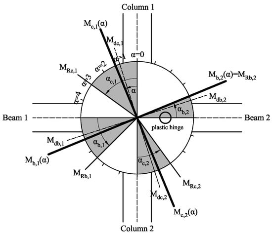
Figure 1.
Legend for column capacity design diagrams in beam–column connections.
Maximum global flexural demand in the connection due to horizontal loads is equal to min{∑MRb;MRc} = ∑MRb, which corresponds to a global overstrength αb = ∑MRb/∑Mdb. In the graphics, αb does not necessarily correspond to the mean value of the overstrengths of both beams, but could be a good approximation in some cases. Thus, a parameter α varying between 0 (corresponding to no horizontal load) and αb (corresponding to maximum horizontal load) can be defined in order to represent the evolution of flexural demand in members due to seismic loading. It is shown in the graphics with a thick line in each quadrant, always within the shadowed area (i.e., the moment in each member is always lower than the resistance). They form a thick “cross”, overlapped to the members, that starts to rotate in the counterclockwise sense.
The angles between the branches of the cross remain all equal to 90° (referred herein as being “synchronised”) because moments in members increase proportionally—homothetically—to their demand in the seismic situation (Mdi). It means that the ratios between stiffnesses of members remain similar if elastic values are considered, because cracking is not taken into account. In a first step, moments in members due to gravitational load in a seismic situation are discarded, as they may be small enough when compared with moment resistances of members.
When any of the branches of the cross reaches the end of the corresponding shadowed area, it means that the member has consumed its resistance and, thus, a plastic hinge is formed in the member end. From this point forward, that branch stays still, as it cannot increase its flexural demand, while the opposite member (which belongs to the same type: beam or column) increases its demand more quickly than the other two elements in order to compensate for the absence of increment in the plastic hinge and, thus, satisfying the equilibrium in the connection. The other two elements of the cross remain, with similar angles, as the constant stiffness ratio is considered.
Then, a second plastic hinge is formed in the next element attaining its flexural capacity. If this element is opposite to the first yielded one, the global moment cannot increase anymore and, thus, the connection flexural demand remains constant from then on. Conversely, if the second plastic hinge is formed in an adjacent member, the process can continue until a third hinge is created.
However, the real evolution of flexural demand can be “not synchronised”, i.e., that relative increments of moment can be different (or even showing a decrease) between members due to cracking and post-elastic redistribution, so the flexural demand is not proportional to the elastic distribution [10]. In the graphics, it is symbolised by a different “rate” of each branch.
Within a connection, if each column’s moment overstrength is compared to each beam’s moment overstrength, four cases can be defined, depending on the value of minimum column overstrength (αc,min) in relation with the minimum (αb,min), maximum (αb,max), and global (αb) overstrength of the beams. In Figure 2, the evolution of moment demand and formation of plastic hinges corresponding to those four cases is shown; the cases are named as A, B, C, and D for the “synchronised” scenario, while, for the “not synchronised” scenario, cases B’, C’, and D’ are considered—as an eventual case A’ would be similar to A.
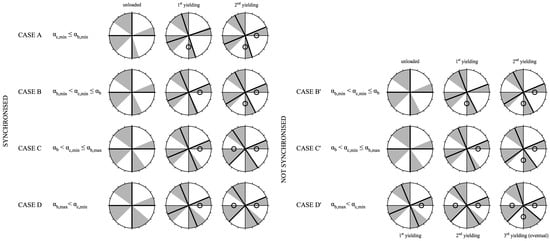
Figure 2.
Diagrams representing different scenarios of evolution of moment demand in members framing into a joint, depending on their relative overstrength values. Legend can be checked in Figure 1.
Case A represents the most unfavourable situation: one of the columns presents less overstrength than both beams. In this case, the first plastic hinge is formed in that column. In case B, that column has an overstrength that is higher than the minimum overstrength of beams but lower than the global one. In this case, the first plastic hinge is formed in the beam with minimum overstrength; from that instant, the opposite beam increases its rate of moment demand, but it is not high enough to reach its resistance before than the column. In case C, the process is similar, but the second beam reaches its maximum before the column does, which has higher overstrength than the global overstrength of the beams. Finally, case D is trivial: if both columns have higher overstrength than each beam, only plastic hinges in beams are formed.
Conversely, considering the “not synchronised” scenario, in case B’, the first plastic hinge can be formed in a column, because of post-cracking moment redistribution; similarly, in case C’ a plastic hinge in column could be formed in the second beam. Furthermore, in case D’, even when both beams have yielded and, thus, the total flexural demand in the connection cannot increase, one of the columns can transfer its moment demand to the other, leading to the formation of a plastic hinge in such a column [10]. One possible reason for such a behaviour may be that if a plastic hinge is formed in a column top for any reason, the rest of the columns in the same storey must increase their shear demand when subjected to a global increment of lateral loads, which could lead to a transfer of moment from the column bases placed above that storey. Thus, the adoption of formulations aimed at preventing the formation of single plastic hinges in columns may be an issue, as it could induce the yielding of other column ends placed at the same height.
In Equation (2), the alternate formulation proposed by the Italian seismic code NTC is shown after being formally adapted to the previous proposed framework. This formulation establish that capacity design of columns could be improved—i.e., causing a lower degree of yielding in columns—with respect to the common procedure (Equation (1)) by ensuring that each column framing the connection is designed to a bending moment amplified by a factor (αc,i), which is equal to γR times the average overstrength of the beams (αb). Subscripts c and b refer to column and beam, respectively; subscripts i and j denotate the number of the column or beam (1 or 2) framing the connection, respectively; Md represents the moment demand in the seismic situation, and α refers to any moment overstrength of members. In this expression, it is assumed that design moments of beams are opposite to moments in columns, so that ∑Mdc,i = ∑Mdb,j in the denominator, considering absolute values.
It is possible to demonstrate that, if synchronisation is assumed, this expression prevents columns from yielding on the condition that the summation of moments in columns due to gravitational loads in a seismic situation is negligible with respect to moments of design and resistance. A generic interior connection, with two columns and two beams (corresponding to subscripts 1 and 2 in each case), is considered. It is supposed to belong to case C, and the beam with identifier 2 is supposed to have higher overstrength than beam 1. Parameter α increases from 0 to αb, and increasing demand in each member is expressed as Mc,i(α) and Mb,i(α) for columns and beams, respectively. Their initial expressions, before the creation of the first plastic hinge in beam 1 (corresponding to a value of α = αy,b1), are those shown in Equations (3) and (4), respectively, where Mg is the moment caused by the gravitational load in the seismic situation, and Mh is the moment caused by the horizontal action alone. In the demonstration, values of moments are positive if they are consistent with the moments caused by lateral loading, i.e., opposite for columns and beams. Given that Mgb,1 and Mgb,2 often show different signs, their summation is not expressed as a summatory but as a difference in absolute values, as shown in Equation (5).
Then, αy,b1 can be obtained by replacing Mb,1(α) by MRb,1 in Equation (4), resulting in Equation (6). For higher values of α, the evolution of moment demand in beam 2 (shown in Equation (7)) must include the aliquot of moment that beam 1 is not able to resist anymore, while columns remain governed by the same expression, because their stiffness ratio remains constant. Consequently, a plastic hinge in beam 2 is created for a value of α = αy,b2, as in Equation (8), and it is obtained by replacing Mb,2(α) by MRb,2 in Equation (7).
Hence, the condition that both columns should satisfy in order to be classified as case C (i.e., not experimenting yielding during lateral loading) is that their resistance should be higher than the demand corresponding to a global value of αy,b2, as shown in Equation (10), obtained from Equation (9). Finally, if ∑Mgc,i is negligible with respect to the moment of design and resistance, then each Mgc,i and Δ|Mgb| are negligible, too (see Equation (5)), so αy,b2 = ∑MRb,j/ΣMdb,j in Equation (8). Thus, the overstrength required in each column in order to not yield is expressed as in Equation (11), which is similar to the formulation suggested in the Italian code (Equation (2)), without accounting for γR.
Consequently, if moments due to gravitational load in beams are quite high but similar in both beams, the formulation of NTC still works. In Figure 3, the first and second scenarios correspond to negligible and not negligible but similar Mgb,j, respectively. The graphic consequence of gravitational moment is that branches start to rotate from an initial angle. Still, the safety factor for columns remains the same in both cases.
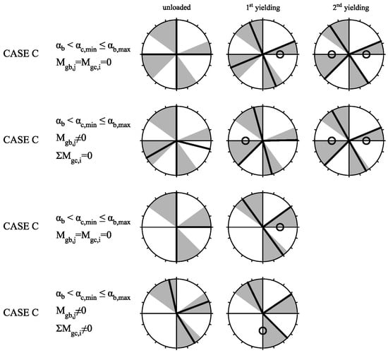
Figure 3.
Diagrams of moment evolution in members framing into a joint for different assumptions of initial moments due to gravitational load in a seismic situation. Legend can be checked in Figure 1.
In Figure 4a,b, columns of an interior connection are capacity designed following EC8 and alternative NTC prescriptions, respectively, in order to evaluate whether the last choice leads to much higher column dimensions than the first one. The design moments of all members and the moment of resistance in beams are similar in both cases; only the resistances of columns change depending on the method. Columns are designed strictly to satisfy strong column–weak beam provisions, regardless of other issues, such as homogenisation of dimensions within the same storey or within the same column spine. Gravitational moments in columns are considered to be negligible.
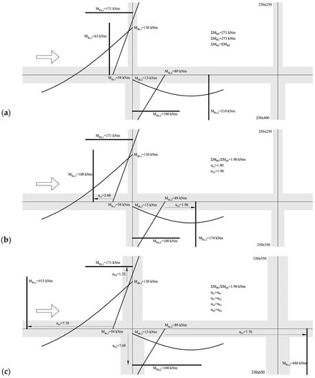
Figure 4.
Example of capacity design of columns of interior connection, regardless of γR, following the procedure of: (a) EC8, (b) alternative NTC, (c) NCSE-02.
For EC8, multiple solutions are possible if ∑MRc ≥ 271 kNm. In the specific solution shown in Figure 4a, the overstrength of the upper column is only 1.17, lower than the minimum overstrength in any beam (1.32); thus, a plastic hinge in that end may form. For NTC, overstrength of both columns must be higher than the global overstrength of beams, leading to more similar values between them. The required global resistance in the columns is 282 kNm in this case, which is slightly higher than in the case of EC8 (271 kNm). It suggests that the application of the alternative formulation of NTC is not necessarily more expensive in terms of material (related to the required resistance); it requires only a higher level of homogeneity between columns.
However, sometimes ∑Mgc,i may not be negligible [11]. This is the case for exterior connections belonging to the penultimate storey—as capacity design is not required in the last storey—especially when the span of beams is large and the seismic design forces are reduced (due to low seismicity or to high values of the behaviour factor q). In this case, the real overstrength of columns can be lower than for the beam, as shown in Figure 3 in the fourth case with respect to the third one, so columns may not be protected against yielding.
If the negative gravitational moment in a beam is higher than the design moment due to only the horizontal load (Mhb,j), then Mdb,j is negative. Thus, it should be introduced in Equation (11) as a negative value. Aimed at avoiding such a concern, NTC replace ∑Mdb,j with ∑Mdc,i, because, in interior connections, gravitational moments in columns are usually low, so Mgc,i ≤ Mhc,i, and Mdc,i and MRc,i are likely to have the same sign.
Still, columns above and below the joint can have design moments with different signs. In this case, EC8 suggests considering every MRc,i as positive, thus assuming that the evolution of moments may be, in both cases, towards the conventional behaviour. Instead, NTC suggests that the alternative formulation (Equation (2)) should be transformed into Equation (12), thus moving the design moment with a different sign (assumed to correspond to subscript 2) from denominator to numerator.
Two typical scenarios are representative of this situation: (i) bottom of exterior columns on the last storey, in which gravitational moment is larger than moment due to horizontal loading and has a different sign; and (ii) the top of the columns on the ground storey belonging to frames with high cantilever behaviour [10], in which Mhc,I < 0.
In case (i), the assumption of EC8 seems to make sense, as the evolution of moments tends to change the sign of such negative gravitational moment. Instead, the proposal of NTC (Equation (12)) may not be justified: similarly to the case in which one of the beams have negative Mdb,j, it is only necessary to introduce both design moments with their corresponding sign in Equation (11). If both columns have negative Mdb,j, then it is impossible to use the NTC formulation, and it would also not make any sense, as gravitational moments would not be negligible. Thus, the suggested formulation in this work (Equation (10)) would be required for enhanced accuracy.
Regarding case (ii), it is not possible to know in advance which would be the evolution of moments in the column top with negative design moment. Assuming linear evolution, moment would remain negative, increasing its absolute value, as shown symbolically in Figure 5. However, between the instant in which a plastic hinge in the column base is formed and the instants in which plastic hinges form in beams beside the column top, it is not possible to know if a moment would change to positive, which could happen if upper column has less overstrength than the beams, and thus yield prematurely. Anyway, the assumption of EC8 is always valid thanks to the similar resistance of columns in both directions—regardless of any variation of axial load. Again, NTC formulation for this case (Equation (12)) may not be justified, as it would be only necessary to introduce both design moments with their corresponding sign.
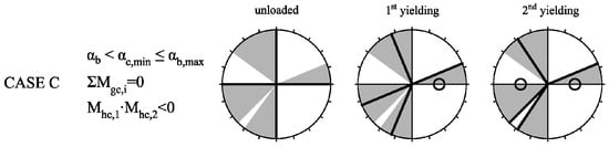
Figure 5.
Diagrams of moment evolution in members framing into a joint when the inferior column presents a negative moment due to only horizontal loading. Legend can be checked in Figure 1.
In [10], an assessment of the seismic performance of several RC buildings designed alternatively to EC8 and NTC (and also to NCSE-02) is carried out. Results show that, especially for frames with wide beams instead of conventional deep beams, the scenario (i) is likely to occur. In those cases, the column-to-beam resistance ratio decreases 17% on average when the NTC alternative formulation is followed with respect to the EC8 procedure (Equation (1)) or to the proposed formulation in this work (Equation (10)) [12]. Still, the overall performance is not substantially influenced in that case because the lower stiffness of wide beams also causes columns must have very large cross-sections in order to provide sufficient lateral stiffness; thus, the column-to-beam ratio is usually higher than the requirements. However, such a decrease in the ratio could lead to an increase in the probability of yielding in other cases with lower column overstrength [7].
Another important discussion is about where the equilibrium of resistances should be verified. Theoretically, it should be carried out in the virtual intersections of the beam–column axes, so the ratio ∑MRc/∑MRb—where the resistances are referred to the face of the joint panel—would be multiplied by (1 + hb/Hcl)/(1 + hc/Lcl), where hb and hc are the average cross-sectional depth of beams and columns framing into the joint, respectively, and Hcl and Lcl are the mean clear height of columns and span of beams of the same elements. This factor is usually higher than 1.00 [1]; thus, the assumption of accounting with the resistances at faces may be conservative.
Such a factor is very sensitive to Hcl and, especially, to hb. For instance, assuming default values of Hcl = 3 m, Lcl = 5 m, hc = 400 mm, and hb = 500 mm, similar reduction of the factor is obtained: when Hcl increases until 3.5 m (+17%), or when Lcl decreases until 2 m (−60%); when hb decreases until 300 mm (−40%), or when hc increases until 2000 mm (+500%, obviously not feasible).
The last shows that such a simplification of the procedure—not taking into account the dimensions of the joint panel—could derive into very different capacity design ratios for wide-beam frames than for deep-beam ones. In [12], a parametric study of the magnitude of the factor (1 + hb/Hcl)/(1 + hc/Lcl) is carried out for representative ranges of values for the different variables: Hcl (2.5, 3.0, 3.5, 4.0, and 4.5 m); Lcl (3, 4, 5, 6, and 7 m); hc (300, 400, 500, 600, and 700 mm); and hb (270, 300, 350, 400, 450, 500, 550, 600, 650, and 700 mm). Regarding beam depth, the first three values (≤350 mm) are considered to represent wide beams, while the rest are identified as deep beams. Results show that mean (and median) values of the factor in the case of deep beams is 1.14, while, for wide beams, it is 1.07 (in both cases with standard deviation lower than 5%). This represents a decrease of 6.2%, which could appear to be insignificant; however, it means that an overstrength factor γR = 1.39 instead of 1.30 (if EC8 is assumed) should be applied to wide-beam frames in order to provide similar conservativeness, which might be hard to achieve in some situations [13]. Furthermore, if it is considered that wide-beam frames designed to DLS in medium-to-high seismicity areas usually present larger column sections than deep-beam frames—in order to compensate for the lower stiffness of beams aimed at satisfying the deformability limitations—and the overstrength factor for wide-beam frames should be even larger.
3. Axial Load in Columns for Capacity Design
Most modern performance-based seismic codes lack of accuracy in the definition of the load case to be considered for the definition of the axial load in columns [1]. Its magnitude has some influence in the determination of the moment of resistance for flexural capacity design of columns, both maximum moment able to be developed in column ends and shear resistance for shear capacity design of columns, and shear resistance of joint panel for capacity design of joints.
Aimed at providing proper performance during a seismic event without requiring complex nonlinear dynamic (time–history) analyses, codes usually establish that 32 different combinations of actions should be considered—(4 directions for the main seismic action) × (2 directions for the secondary transverse seismic action) × (4 different positions of the barycentre of masses in each storey due to accidental eccentricity). Thus, four different seismic combinations can be ascribed to each direction of the evaluation of axial force in columns.
A summary of the different criteria of some international seismic codes (including New Zealander NZS 3101 [14] and American ACI 318-08 [15]) for the adoption of axial forces in columns is shown in Table 1; note that the contents are not the literal texts in the codes but an interpretation of those provisions in a more explicit way.

Table 1.
Interpretation of the different criteria for the election of the value of axial load in columns adopted for the calculation of bending moment of resistance for capacity design purposes.
Often, codes suggest to adopt the most conservative value of axial force of those four combinations, by using the expression “within the range of values”, and it is not clear whether it refers to choosing one of those four discrete values or, conversely, a value contained in the continuous range. Note that, as the interaction diagram moment-axial is pseudo-parabolic, the most conservative value could not be neither the maximum nor the minimum. Moreover, it is not clear whether an additional combination should be considered corresponding to only gravitational seismic load. Conversely, in other cases, codes suggest that axial load should be chosen from all the seismic combinations, independently of the direction. Also, at other times, it seems that it is suggested to adopt 4 new combinations, in addition to the other 32, without accidental eccentricity and without combining with transverse action, from which axial load is directly taken. Furthermore, some codes propose obtaining axial load as an addition of the force coming from seismic gravitational load and the increment or decrease produced by the global frame action when the maximum admissible horizontal loading is acting, i.e., the variation of axial consistent with maximum shear forces in all beam ends.
Analogously, it is not explicitly stated whether the moment of resistance in the relevant direction should be obtained in the presence of any transverse moment, corresponding to any of the seismic combinations, consistent or not with the direction, from specific combinations for capacity design (without combining with transverse action) or even from seismic gravitational combinations.
Capacity design provisions may be somehow understood as a set of simple rules that are intended to provide quite degree of conservativeness against undesirable behaviour. Obviously, they come from an agreement between accuracy, simplicity, and feasibility. However, regarding the assumption of axial loads in columns aimed at calculating the moment of resistance, some non-conservative scenarios could eventually occur. Exterior columns of frames can experience significant variation of axial demand when subjected to horizontal loads if compared with the initial (default) state or are only subjected to vertical loads in the seismic situation. Theoretically, it is not clear whether the most critical situation is an increase or a decrease in axial load. However, in capacity designed buildings, the relative axial load may be medium-low [16]; thus, a decrease in axial load may be the most unfavourable scenario.
This evolution of axial load in columns may be understood within the behaviour of the frame when subjected to an incremental monotonic pattern of lateral forces from the initial situation—under only gravitational loads in the seismic situation—until reaching each one of the seismic situations, when the whole design seismic force is acting. In a real earthquake, without accounting for overstrength sources, it can be assumed that, if a global demand q times lower than design PGA is required, the structure may remain elastic, so the evolution of the axial load until those levels may be proportional to the global demand.
Still, axial load in any of those situations is consistent with bending moments acting in all member ends that are lower than the corresponding maximum flexural capacities, thanks to overstrength and capacity design. The scope would be to calculate moment resistances of columns in the presence of axial loads actually consistent with such maximum values of moment instead of being consistent with design moments, i.e., axial loads consistent with global maximum frame action. Within the linear incremental lateral-force framework, axial loads in exterior columns would proportionally decrease from the “design state” (design moments in both ends) until the “capacity state” (maximum moments in both ends, which, in time, depend of the level of axial load attained).
It could be possible that positive (tension) values are attained, especially in frames designed to DLS in medium-high seismicity areas, because large cross-sections are demanded due to stiffness requirements, and, thus, they show low relative axial loads in the initial situation (under seismic gravitational loads). For the same reason, those frames also show low reinforcement ratios, usually based on minimum required values [10]. In this case, a substantial reduction of axial load may cause an important decrease in flexural capacity. For instance, in a column with a minimum reinforcement ratio (1%) regularly distributed in the perimeter, a decrease in relative axial load from 0.4 to 0.0 entails a loss of flexural capacity of 35–40%, while, for a column with high reinforcement ratio (3%), the loss is only about 10–15%. Hence, in exterior columns of frames presenting higher overstrength of members, non-conservative scenarios of capacity design of columns could occur.
Herein, a variation of the usual procedures of codes, based in the previous considerations, is proposed and illustrated by a representative example of a generic exterior column with square cross-section and minimum reinforcement. In all of the examples in Figure 6, the 3D axial-moment interaction envelope representing the resistance of the column end is shown, consisting in a surface generated by the 90° revolution of the plane curve, which is rather similar to a parabola.
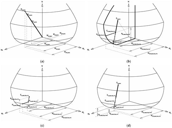
Figure 6.
Alternative proposal for axial loads in columns for the calculation of moment resistances in columns for capacity design: (a) definition of initial seismic state; (b) finding moment resistance; (c) finding more realistic moment resistances by accounting for different overstrength between beams and columns; and (d) axial load for shear capacity design.
In Figure 6a, a typical non-seismic design procedure is shown. The thick line joining the origin with the surface is a vector representing, in this case, the linear evolution of the internal forces (axial N, longitudinal bending moment Mz, and transversal bending moment My) in the column caused by gravitational actions. The intermediate points symbolized by the letter E with different subscripts represent different design situations, while the points symbolized by the letter R represent the resistance of the columns when subjected to forces increased proportionally with respect to the design situations. The ratio between lengths of vectors reaching R and reaching E represents the safety factor of the column in each design situation.
In the same figure, both Ed,pers and Rd,pers refer to the persistent/transient situation of the design, while Ed,grav refers to the state of the column only subjected to gravitational loads in the seismic situation. The last point can be obtained graphically by multiplying the vector modulus by (1.35G + 1.50Q)/(G + 0.5Q), which are G and Q, the dead and live loads, respectively. That vector is aligned with the previous one only if the forces caused by wind loads are lower than those caused by gravitational loads in the persistent/transient situation. Each one of those three points is related to values of Mz and My, identified in the figure with the corresponding subscripts. As values of My are relatively small, the vector is almost parallel to the plane Mz–N. The relative axial load corresponding to seismic gravitational loading in this case is about 0.4.
In Figure 6b, the vector representing the evolution of forces when the frame is laterally loaded is plotted. Its origin is Ed,grav, and its direction is oriented to the point Ed,seis,hie,c>b, which represents the tensional state of the column in the specific seismic combination (subscript seis) for capacity design of columns (hie,c > b, from “hierarchy column-beam”), i.e., without accidental eccentricity of masses and without combining main horizontal action with 30% in the perpendicular direction. This point is characterised by a lower axial load (because the column is exterior) and a transverse moment insignificantly different from that of Ed,grav. In the figure, the vertical section of the resistance envelope, plotted with a thick line, contains Ed,seis,hie,c>b and represents the resistance curve assuming constant My.
Usually, codes suggest obtaining the Mz of resistance by assuming constant N, which is equivalent in the diagram to moving horizontally from Ed,seis,hie,c>b until reaching the envelope in the point Rd,seis,hie,c>b, corresponding to a moment of resistance MzR,seis,hie,c>b. Actually, some codes suggest to do this “horizontal itinerary” starting from different axial values and choosing the lower MzR, as discussed previously.
Instead, the alternative procedure proposed in this work is based in the proportionality of forces: it is assumed that the increment of the three internal forces must be proportional [17], so the maximum flexural capacity of a column end must be consistent with the direction of the vector matching the gravitational situation with the seismic one. It is represented in Figure 6b as Rd,seis,hie,c>b’, with MzR,seis,hie,c>b’ being the alternative moment resistance associated to this state. It corresponds graphically to the intersection of the resistance surface with the vector whose direction is determined by Ed,grav and Ed,seis,hie,c>b. It is worth noting that the alternative flexural resistance can be substantially lower than the value obtained by the classic method, especially for low-reinforced columns in which the seismic situation is not so much more demanding than the persistent/transient one.
Nevertheless, the axial corresponding to the development of full flexural capacities in columns is actually never acting, because such capacities are not able to be attained. In fact, the capacity design of columns causes maximum moments in column ends that are reduced by a factor ∑MRb/∑MRc. When such reduction is applied, an intermediate state between Ed,seis,hie,c>b and Rd,seis,hie,c>b’ may be reached, as shown in Figure 6c.
EC8 allows using this reduction for the consideration of the flexural demand in column ends aimed at shear capacity design. Thus, an axial load Nd,seis,hie,V>M’, consistent with this intermediate state Ed,seis,hie,V>M, could be used for the estimation both of the shear demand based on the maximum moment developed by column ends and the shear capacity.
Either way, this alternative procedure presents some weaknesses: it is deterministic; it could become unconservative for columns whose compression increases when the frame is subjected to seismic action; the evolution of moments in member ends is not necessarily proportional after the first yielding in any element; and maximum capacities in columns cannot be attained. Hence, it may be understood as an alternative procedure that adds one more value of moment resistance to the range from which the minimum value should be chosen.
In [12], the seismic assessment of several medium-height RC frames with different type of beams and levels of ductility showed that, at the target displacement consistent with the Ultimate Limit State, the level of compression of some perimeter columns was reduced up to 65%, which, in some cases, led to a decrease in moment resistance under the limits of the provisions for frames with deep beams.
Actually, the most precise approach for the evaluation of the moment of resistance for flexural capacity design of columns can be found in NZS 3101 [14]. It evaluates the axial load in a column corresponding to the maximum horizontal action in the frame by assuming that all beam ends develop maximum flexural capacities accounting for the overstrength factor (see Table 1). Thus, the axial load in a single column results from the addition of the compression due to gravitational load in the seismic situation plus the maximum shear forces of all beam ends framing into joints placed above the column in its same vertical. Note that, in this case, overstrength factor is considered twice: for the evaluation of axial load and also for the “a-posteriori” evaluation of the degree of capacity design.
In Figure 6d, the demand point in agreement with the attainment of maximum capacities of beam ends is plotted as Ed,seis,hie,c>b′, and their corresponding resistance point and flexural capacity are expressed as Rd,seis,hie,c>b′ and MzR,seis,hie,c>b′, respectively. This method provides similar values to the alternative method proposed in the present work only if all the ratios ∑MRb/∑MRc above the evaluated column end are equal to the overstrength factor adopted.
Notwithstanding its great accuracy and coherence, the main shortcoming of the last method is that the evaluation of too many members (all the beams framing to joints placed above the evaluated connection) is aimed at designing each column end, instead of referring only to the capacities of the beams framing to the same joint. Also, the axial load corresponds to the formation of the last plastic hinge in beams of all the storeys above the column, which may be different from the axial load corresponding only to the yielding of beam ends framing the actual joint.
All of the precedent leads one to consider that, in capacity design of column frameworks, γR may be understood as a global “safety factor” which not only has into account for the possible overstrength of materials but also represents the degree of robustness of the structure against all of those weaknesses that could cause yielding of column ends in some situations. In fact, inelasticity in columns is quite difficult to avoid completely [7,8].
4. Capacity Design Provisions of Spanish Seismic Code NCSE-02
Notwithstanding the discussion on the accuracy of some specific statements of the different seismic codes, general prescriptions in the form of Equation (1) may be appropriate in order to provide capacity design to structures within a reasonable level of conservativeness, considering the multiple uncertainties associated with the behaviour other than material hardening: upper slab contribution to flexural capacity of beams, biaxial bending of columns, etc. [7].
However, current Spanish seismic code NCSE-02 does not adopt such a framework [12]. A new seismic code, NCSR-22 [18], based on Eurocode 8, is currently being developed, but it is not yet mandatory. Nevertheless, it is important to have enough understanding of the efficiency of the provisions of previous seismic codes aimed at proper assessment of existing structures, especially in the case of simplified vulnerability procedures based on the age of construction of buildings [19].
NCSE-02 provides different rules that present some deficiencies if analysed in detail: sometimes they are impossible to apply, and other times they can be inefficient or, conversely, they can compel the design of members with excessive overstrength. Also, they do not provide quantitative formulations for calculating some resistances, they provide very low values of γR even for high ductility, and, in general, they do not provide proper guidelines for the application of such rules in order to face all the possible particularities; thus, it has not been incorporated by any widespread Spanish software for practical design [20].
NCSE-02 compels one to provide higher overstrength to columns than to beams and also higher overstrength for shear than for moment. Plastic hinges in members should correspond to the yielding of steel; the last may not correspond to any capacity design provision but to a consequence of proper local detailing. A constant value of γR = 1.10 is recommended for any structural type and ductility class.
Still, the capacity design rules of NCSE-02 consist of just four paragraphs of text written in a very general sense, without any equation, quantitative expression, or clarifying figure. It may reflect a shallow understanding of the phenomenon. It contains only general proposals, but it actually does not provide enough tools to the designer in order to solve a wide range of possible scenarios [20].
The issue with those provisions is that they are based in the concept of overstrength instead of capacity, i.e., they compel the prevalent member (or type of force) to possess higher overstrength than the not-prevalent one, instead of designing the prevalent member (or type of force) to the maximum force in agreement with the development of the maximum capacities of the non-prevalent one. Paradoxically, such a framework based on overstrength causes inefficiency when applied to shear capacity design, but, conversely, it causes excessive—likely impossible to manage—overstrength when applied to joints’ and columns’ capacity design.
Moreover, unlike EC8 or other benchmark codes [12], it does not specify lots of practical issues: how many vertical plans and directions of loading should be checked; which axial load in columns should be considered in order to evaluate flexural resistance; where to set the equilibrium of forces for capacity design of columns (in faces or in axe of joint panels); how to consider overstrength factor when demand and resistance have different signs; which elements or structural types are suitable to be exempt from capacity design; how to account for the contribution of upper slab to the capacity of beams; how to account for the cyclic degradation of resistances or confinement improvement; how to calculate demand and capacity in joint panels; how to account for confinement provided by beams; and how to improve capacity of joints with stirrups.
NCSE-02 states that capacity design of columns is attained when “overstrength of each force in each column is higher than corresponding overstrength of each force in all beams” framing into the joint between columns. First of all, “each force” may be understood as “each type of force”, i.e., bending moment in both axes, shear in both axes, axial, and torsion. It may be also understood that each resistance value associated with each design force may be evaluated assuming that the rest of the forces remain constant. Establishing hierarchy between types of forces different from the vertical bending moment is not only unnecessary but also counter-productive. It is unnecessary because the physical principle that is pursued is the formation of plastic hinges in beams rather than in columns, and this is only possible for bending moment action (in the presence of other types of forces with lower magnitudes). It is not possible to form plastic hinges with only axial, shear, or torsion forces. Moreover, capacity design of members prevents shear failure. It seems that each capacity design rule does not consider the consequences of the other ones. Finally, it is counter-productive because those secondary types of forces (axial load in beams, perpendicular moment and shear, torsion) are usually very low in comparison with resistances; thus, overstrength values can reach extremely large values that can be very difficult to exceed with the corresponding overstrength in columns.
There is a similar problem regarding capacity design of joints: “overstrength in any strut or tie within the joints higher than any force of each beam or column framing the joint”. Also, including columns in the prescription is not in agreement with capacity design of columns: they cannot develop their full resistance because beams yield prematurely.
Apart from those negligible deficiencies, the main problem of the “overstrength framework” is that the comparison is performed between single values instead of couples of values. In Figure 4c, an example of the capacity design of columns, as established in NCSE-02, is shown. Bottom reinforcement of beams is usually constant in the full length of the member. Thus, if the positive moment due to horizontal loading is quite different in both ends, the end with lower moment would have much higher overstrength. Also, if gravitational moment is high in comparison with seismic demand, a higher positive moment would be reached at mid-span than in the ends. In both cases, it is possible that one of the beams framing the joint has very high overstrength (7.69 in this case), thus leading each column to have at least that overstrength. Instead, if the connection is designed to EC8 (Figure 4a), the global overstrength required for both columns is only 1.90, and, if NTC is followed (Figure 4b), such a value is required for each single column. The reason for this decrease is that the demand in columns depends on two values (resistances of beams at both sides) instead of only one; they “compensate” each other. The required dimensions for columns are extremely large in the case of NCSE-02. Moreover, as overstrength of beams may increase in upper storeys (because minimum reinforcement and gravitational forces may determine design), it could be possible that higher dimensions are required for upper storeys than in bottom storeys, which is absurd.
In [10], an assessment of several RC frames designed to NCSE-02 as in real engineering practice, i.e., with no observation of capacity design, has been carried out. The results show that, in comparison with EC8, the seismic safety factor is 22% lower on average.
Analogous problem can be observed for the capacity design of joints. In the case of EC8 (Figure 7a), demand on joints depends on the resistances of both beams, while, in the NCSE-02 approach (Figure 7b), the joint must be designed to reach the maximum overstrength of the two beams. Actually, the mathematical problem of “overstrength framework” is that overstrength is a ratio, i.e., it is based on multiplication, while “capacity framework” is based on addition. When design values are very small, overstrength ratios grow without any control, while the decrease in global capacities is more controlled by the addition.
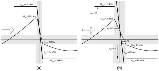
Figure 7.
Example of capacity design of joints of interior connection, following the procedure of EC8 (a) and NCSE-02 (b).
Regarding shear capacity design of members, NCSE-02 compels “each section to have more shear overstrength than moment overstrength”. Imposing such rule to sections placed in the intermediate part of the member would lead to enormous required shear overstrength values around the point of the member where design moment is zero.
For a better understanding, in the following the specific case of columns is considered (constant values for design and resistant shear forces), and γR is not taken into account. Conversely to joints’ and columns’ capacity design, in this case the strategy of comparing single overstrengths does not lead to excessive overstrengths in both ends but only in the end with lower moment overstrength.
In Figure 8, the procedure suggested by NCSE-02 is shown. A generic column is considered, whose linear distribution of design moments is not symmetric, being Mdc,2 ≥ Mdc,1. Thus, the shear span lengths (LVi) are different and can be related by a ratio fLv, as in Equation (13), and also with the total height of the column (L), as in Equation (14). Each member end has a moment overstrength αc,i, as defined in Equation (15); shear overstrength must be equal to or higher than this value on each end. On the other hand, “plastic shear”, i.e., shear force obtained from the application of opposite moments of resistances at column ends (Vpc), is considered to be the target shear resistance in order to ensure capacity design. Hence, target shear overstrength (αVdc) is defined as in Equation (16).
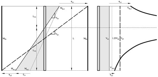
Figure 8.
Shear capacity design of columns according to NCSE-02.
Design shear force is the ratio between design moment in any end and its corresponding shear span. In Equation (17), LV2 is replaced by the expression shown in Equation (14), and the ratio between the maximum design moment (Mdc,2) and L is isolated. Similar isolation is carried out in Equation (18) for the expression of plastic shear, in which the moment of resistance is expressed as dependent on Mdc,2. Then, in Equation (19), both expressions of Mdc,2/L in previous Equations (17) and (18) are equalised.
Equation (19) relates target (plastic) shear with design shear. Target shear overstrength can be expressed (Equation (20)) as function of the “shape” of design moments (reflected in the shear span factor fLv) and the minimum moment overstrength (corresponding to end 2) or, conversely, to maximum moment overstrength (end 1). Thus, at each end of the column, the ratio between shear overstrength required by NCSE-02—which must be at least equal to moment overstrength—and target shear overstrength depends only on fLv (Equation (20)).
Hence, in order to evaluate the reliability of the rule in NCSE-02, i.e., if the rule results in shear resistances higher than target values, in Equation (21), the values of fLv necessary to ensure conservativeness for each column end are obtained. For the end whose design moment is the minimum (end 1), any value of fLv satisfies the condition (because it is always higher than 1, see Equation (13)); thus, shear design is always conservative. Conversely, for the column end whose design moment is the maximum (end 2), only a value of fLv = 1 derives in conservativeness. Hence, it is demonstrated that the NCSE-02 rule is not conservative for columns in which design moments are different in both ends.
In Figure 9a, safety factors (i.e., the ratio between shear resistance imposed by the code and the target shear intended to provide capacity design) of both ends for different shapes of design moments are shown. It is worth noting that not only is the rule not conservative for one of the ends, but, for the other end, the required overstrength can reach values which may be impossible to be provide to the section. This may be representative, for example, of 1st storey columns of wide-beam frames, in which design moments at the base may be much higher than moments at the top due to cantilever behaviour [10].
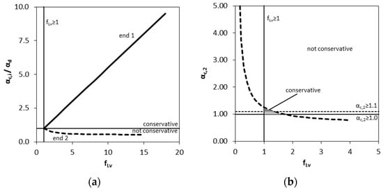
Figure 9.
Conservativeness of shear capacity design of columns depending on shear span proportion, without (a) and with (b) consideration of the increment of 25% to shear of design suggested by NCSE-02.
Still, NCSE-02 establishes that, for medium and high seismicity, VRc ≥ 1.25Vdc in all the length of the column, where VRc is the shear resistance and Vdc is the shear force design. Thus, it could be possible that the weakness of the capacity design rule in the unfavourable end gets overshadowed by that 25% amplification.
Equation (22) evaluates the case in which a shear resistance equal to the 25%-amplified shear demand is higher than the target shear; Equation (20) is replaced into this expression. It is concluded that the design may be conservative only for quite reduced values of overstrength in the unfavourable column and very symmetric (in absolute values) distribution of design moments. In Figure 9b, this tiny sub-space is indicated in soft grey. Moreover, if it is considered that moment overstrength must be at least 1.10, aimed at satisfying capacity design of columns (except for the base of columns in the ground storey), such sub-space is even more reduced (marked in dark grey).
In columns, very often similar arrangements of stirrups are placed on the top and bottom ends; thus, in practice, the weakness of the capacity design rule for shear of NCSE-02 may be overcome. However, both ends should be designed for shear values that can be extremely high. It is not clear in which cases such high values become overshadowed by local detailing provisions on minimum stirrups in critical regions, but, still, the capacity design rule may not be acceptable. In beams, it is not so easy to individuate the not-conservative scenarios, because moments of resistance and target plastic shear are neither similar in both ends nor in the two directions, and the vertical load changes both values.
It is worth noting that NCSE-02, in its comments, says that “it is easier to provide capacity design of columns with deep beams than with wide ones”. In fact, the contribution of the upper slab could be higher for wide beams [21], and, also, gross width could be uncertain. Also, the geometry of the joint panel can be slightly unfavourable for wide-beam frames. It is not clear if NCSE-02 refers to those phenomena.
5. Conclusions
In this paper, we examine the fundamentals and effectiveness of capacity design provisions of three current European seismic codes—Eurocode 8, Italian NTC, and Spanish NCSE-02. Other international codes, such as American ACI 318-08 or New Zealander NZS 3101, are occasionally used as benchmarks for comparison. The different scenarios of performance are classified, and the balance between accuracy, robustness, and simplicity is taken into consideration. Three main aspects came from this study:
- The alternative formulation proposed by Italian NTC for the capacity design of columns may not be suitable when: (i) design gravity moments are neither negligible nor homogeneous at both sides of the joint; and (ii) when columns above and below the joint show opposite design moments due to gravity loads in higher storeys or to the cantilever effect in the first storey. Equation (10) is proposed in this work in spite of its higher complexity.
- The procedures suggested by most codes for the calculation of axial load in columns, for both their capacity design to shear and moment, could be unconservative, especially for perimeter columns, which could eventually drastically reduce their compression. An alternative method based on a proportional evolution of axial load during seismic events is proposed as an additional load case to be integrated within the whole set of seismic cases.
- None of the provisions of the Spanish NCSE-02 are effective for ensuring capacity design because they are based on overstrength ratios instead of capacities, resulting in absurd values if considered literally. Hence, any simplified vulnerability method based on the age of the construction of buildings should consider Spanish RC structures as not being capacity designed.
The relative influence of the proposed code changes on the seismic structural performance when compared to other provisions (e.g., lateral stiffness for Damage Limitation Limit State) depends on the specific characteristics of the structure and the event, and its evaluation is beyond the scope of this paper. However, in all three cases, there is practical evidence of the plausibility of the scenarios in which the unsuitability of the current provisions is demonstrated.
Author Contributions
Conceptualization, methodology, validation, writing, F.G.-M.; data curation, A.P.-G. All authors have read and agreed to the published version of the manuscript.
Funding
This research received no external funding.
Data Availability Statement
Not applicable.
Conflicts of Interest
The authors declare no conflict of interest.
Nomenclature
| ∑MRb | Summation of moment resistances of beams at both sides of the joint |
| ∑MRc | Summation of moment resistances of columns above and below the joint |
| As1 | Tensioned reinforcement area |
| Ed,grav | Design force in a column only subjected to gravitational loads in the seismic situation |
| Ed,pers | Design force in the persistent/transient situation |
| Ed,seis,hie,c>b | Design force in the column in the specific seismic combination for capacity design of columns |
| Ej | Maximum value of the force able to be developed by the not-prevalent element or type of force i |
| fLv | Shear span length ratio |
| G | Dead loads |
| hb | Beam cross-section depth |
| hc | Column cross-section depth |
| Hcl | Clear height of columns |
| Lcl | Clear span of beams |
| LV | Shear span length |
| Mdb | Design moment of the cross section of a beam framing a connection |
| Mgb | Moment in a beam caused by the gravitational load in the seismic situation |
| Mhb | Moment in a beam caused by the seismic action |
| Mhb | Moment in a column caused by the seismic action |
| MRb | Moment resistance of the cross section of a beam framing a connection |
| My | Bending moment in the perpendicular direction |
| Mz | Bending moment in the main direction |
| N | Axial load |
| nb | Number of beams framing a connection |
| nc | Number of columns framing a connection |
| Q | Live loads |
| Rd,pers | Resistance in the persistent/transient situation |
| Rd,seis,hie,c>b | Resistance in the column in the specific seismic combination for capacity design of columns |
| Rd,seis,hie,c>b’ | First alternative resistance in the column in the specific seismic combination for capacity design of columns |
| Rd,seis,hie,c>b′ | Second resistance in the column in the specific seismic combination for capacity design of columns |
| Ri | Resistance of the prevalent element or type of force i |
| Vpc | Shear force obtained from the application of opposite moments of resistances at column ends |
| α | Parameter ranging [0,αb] for the moment demand of a connection |
| αb | Global moment overstrength of beams framing a connection |
| αb,max | Maximum beam moment overstrength |
| αb,min | Minimum beam moment overstrength |
| αc,min | Minimum column moment overstrength |
| αVdc | Global shear overstrength |
| γR | Overstrength factor |
References
- Fardis, M.N. Seismic Design, Assessment and Retrofitting of Concrete Buildings: Based on EN-Eurocode 8; Springer: Berlin/Heidelberg, Germany, 2009. [Google Scholar]
- Surana, M.; Singh, Y.; Lang, D.H. Effect of strong-column weak-beam design provision on the seismic fragility of RC frame buildings. Int. J. Adv. Struct. Eng. 2018, 10, 131–141. [Google Scholar] [CrossRef]
- Nie, X.; Zhang, S.; Jiang, T.; Yu, T. The strong column—Weak beam design philosophy in reinforced concrete frame structures: A literature review. Adv. Struct. Eng. 2020, 23, 3566–3591. [Google Scholar]
- EN 1998-1:2003; Eurocode 8: Design of Structures for Earthquake Resistance—Part 1: General Rules, Seismic Actions and Rules for Buildings. Comité Européen de Normalisation: Brussels, Belgium, 2004.
- NTC-08; Norme Tecniche per le Costruzioni. Decreto Ministeriale, 14. Ministero delle Infrastrutture e dei Trasporti: Rome, Italy, 2008. (In Italian)
- NCSE-02; Norma de Construcción Sismorresistente. n. 244. BOE: Madrid, Spain, 2002. (In Spanish)
- Panagiotakos, T.B.; Fardis, M.N. Effect of column capacity design on earthquake response of reinforced concrete buildings. J. Earthq. Eng. 1998, 2, 113–145. [Google Scholar]
- Kuntz, G.; Browning, J.A. Reduction of column yielding during earthquakes for reinforced concrete frames. ACI Struct. J. 2003, 100, 573–580. [Google Scholar]
- Wongpakdee, N.; Leelataviwat, S. Influence of column strength and stiffness on the inelastic behavior of strong column—Weak beam frames. J. Struct. Eng. ASCE 2017, 143, 04017124. [Google Scholar]
- Gómez-Martínez, F.; Alonso-Durá, A.; De Luca, F.; Verderame, G.M. Seismic performances and behaviour factor of wide-beam and deep-beam RC frames. Eng. Struct. 2016, 125, 107–123. [Google Scholar]
- Gómez-Martínez, F.; Millen, M.D.L.; Alves Costa, P.; Romão, X. Estimation of the potential relevance of differential settlements in earthquake-induced liquefaction damage assessment. Eng. Struct. 2020, 211, 110232. [Google Scholar]
- Gómez-Martínez, F. FAST Simplified Vulnerability Approach for Seismic Assessment of Infilled RC MRF Buildings and Its Application to the 2011 Lorca (Spain) Earthquake. Ph.D. Thesis, Technical University of Valencia, Valencia, Spain, 2015. Available online: hdl.handle.net/10251/54780 (accessed on 8 November 2022).
- Gómez-Martínez, F.; Alonso-Durá, A.; De Luca, F.; Verderame, G.M. Ductility of wide-beam RC frames as lateral resisting system. Bull. Earthq. Eng. 2016, 14, 1545–1569. [Google Scholar] [CrossRef]
- NZS 3101 part 1; Concrete Structures Standard: Part 1—The Design of Concrete Structures. New Zealand Standards: Wellington, New Zealand, 2006.
- ACI 318-08; Building Code Requirements for Structural Concrete and Commentary (318-08). American Concrete Institute: Farmington Hills, MI, USA, 2008; ACI Committee 318.
- Ning, N.; Qu, W.; Ma, Z.J. Design recommendations for achieving “strong column–weak beam” in RC frames. Eng. Struct. 2016, 126, 343–352. [Google Scholar] [CrossRef]
- Zhang, C.; Tao, M.-X. Strong-column-weak-beam criterion for reinforced concrete frames subjected to biaxial seismic excitation. Eng. Struct. 2021, 241, 112481. [Google Scholar] [CrossRef]
- CPNS. Audiencia e Información Pública Sobre el Proyecto de Real Decreto por el que se Aprueba la Norma de Construcción Sismorresistente NCSR-22. Real Decreto de Consejo de Ministros, Madrid, Spain. 2023. Available online: https://www.mitma.gob.es/el-ministerio/buscador-participacion-publica/audiencia-e-informacion-publica-sobre-el-proyecto-de-real-decreto-por-el-que-se-aprueba-la-norma-de-construccion-sismorresistente-ncsr-22 (accessed on 7 August 2023). (In Spanish).
- De Luca, F.; Verderame, G.M.; Gómez-Martínez, F.; Pérez-García, A. The structural role played by masonry infills on RC building performances after the 2011 Lorca, Spain, earthquake. Bull. Earthq. Eng. 2014, 12, 1999–2026. [Google Scholar] [CrossRef]
- Gómez-Martínez, F.; Pérez-García, A.; De Luca, F.; Verderame, G.M. Infilled RC buildings performances during the 2011 Lorca, Spain, earthquake: Application of FAST approach. Inf. Construcción 2015, 67, e065. [Google Scholar] [CrossRef]
- Gómez-Martínez, F.; Pérez-García, A. Yielding and ultimate deformations of wide and deep reinforced concrete beams. Buildings 2022, 12, 2015. [Google Scholar] [CrossRef]


Disclaimer/Publisher’s Note: The statements, opinions and data contained in all publications are solely those of the individual author(s) and contributor(s) and not of MDPI and/or the editor(s). MDPI and/or the editor(s) disclaim responsibility for any injury to people or property resulting from any ideas, methods, instructions or products referred to in the content. |
© 2023 by the authors. Licensee MDPI, Basel, Switzerland. This article is an open access article distributed under the terms and conditions of the Creative Commons Attribution (CC BY) license (https://creativecommons.org/licenses/by/4.0/).