Abstract
Although glass façades have been on the market for over a century, new improvements, following sustainable standards, are still being invented. An improvement of the actively maintained CCF has occurred in passive maintenance with natural ventilation of the cavity and insulation glass unit placed on the external side, which has served as a true motivation for further research. To develop the idea, a new type of CCF was invented, followed by the creation of the software, whose purpose is to determine optimal CCF façade components. During this research, an experimental and mathematical model was made regarding the thermal behavior, later validated by the measurements on-site in Rugvica, Croatia. Using simplified but unconventional methods, numerous formulae and variables, a simulation of climatic loads onto the CCF was conducted. Validations of the thermal model were made during winter and summer periods for southern and western façade orientation, explaining how heat transfers from the environment to close cavity façade elements. It was found from the analysis that air temperatures of the façade elements follow the outer air temperature, by constant air exchange with the outer space. The results showed great potential with up to 3 °C (5–10%) of difference in experimental and calculated results, thus creating a basis for further improvement of the software with the addition of structural and hygric behavior of the façade element, regarding climate conditions.
1. Introduction
A close cavity façade is a type of double-skin façade (DSF), which was developed by improving the benefits of double-skin façades (such as protected sun blinds, lowered cooling, and heating needs with a U value < 0.7 W/m2K) with the advantages of single-skin façades (such as clean air cavity providing lower maintenance costs, having only two glass surfaces to maintain, and less reduction of floor area having larger depth to the outside). The greatest weaknesses of the close cavity façades are unavoidable excess temperatures and pressures in the façade and the risk of condensation between two skins requiring the ventilation of the cavity [1]. Standard closed cavity façades are composed of an insulated glass unit (IGU) on the inside, a closed cavity (maintained by mechanical air supply), an external single glass pane, and an aluminium frame with a thermal bridge break (Figure 1a) [2]. During the research of the “Development of a double facade with a hermetically sealed cavity H-CCF” project, made by the University of Zagreb Faculty of Architecture, and KFK company, enhancements of the close cavity façade were made to nullify energy needs for active maintenance of the air gap. The newly developed—passively maintained closed cavity façade, commercially named ACS, consists of an external IGU unit, a naturally ventilated cavity, an internal single glass pane, and an aluminium frame with a thermal bridge break (Figure 1b). A CTE mismatch is solved by placing a PVB foil between the laminated glass layers. The major steps forward, outcoming from this research are the passive moisture control by thin capillary and IGU on the outside. Capillary is placed between outer air and air cavity, which provides the natural airflow to and from the cavity, eliminating excessive pressures and minimizing the risk of condensation and dust inflow. Condensation above 6% is passively controlled by the desiccant placed inside the frame. Insulated glass unit placed on the outside, provides lowered temperatures during summer, and consequently pressures, while also contributes to higher temperatures during winter reducing the risk of condensation. Argon and air gap together create double barrier conditions for better thermal comfort of the interior.
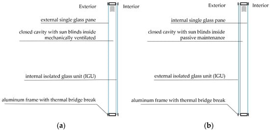
Figure 1.
Schemes of façade elements in (a) standard—mechanically driven and (b) passively maintained—naturally ventilated close cavity façade [3].
Energy efficiency and sustainability in the building sector are crucial for achieving the 2030 Agenda for Sustainable Development Goals (SDGs), especially regarding Goal 7: Affordable and Clean Energy and Goal 12: Responsible Consumption and Production. Buildings play a significant role in contributing to climate change and environmental degradation due to their energy consumption, resource usage, and waste generation [4]. Passive solutions in the building industry have a primary role in achieving greater sustainability without excessive energy consumption. These solutions often involve strategic building orientation, and optimal thermal performance to reduce the need for heating, cooling, and ventilation. Physical processes happening inside the close cavity façades are mostly affected by the climate conditions and the façade’s response to them (Figure 2). Solar irradiance absorption affects heat transfer and consequently, pressure equalization, moisture control, air supply, and glass deflection. All these processes mutually affect the façade, which can be observed in its thermal, structural, and hygric behavior. Thermal behavior serves as a starting point for observing the interspace of the façade, as the rise in temperature increases the pressure, while a drop in temperature decreases the pressure. Equalizing the cavity and pressure with the surrounding atmospheric air causes over—or under-pressure inside the cavity. Due to air suction and deflation regarding pressure equalization, structural behavior of the glass panes results in deflection under the influence of cyclical changes in climatic conditions. As the glass deforms, there is a change in air volume inside the cavity, the pressure decreases and most of the load disappears.
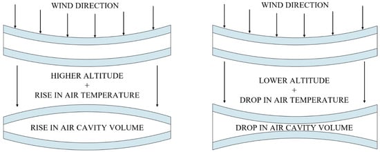
Figure 2.
Wind and climatic loads affecting the structural behavior of the façade element.
Hygric behavior is directly related to air supply from the outside, as the air supply also introduces humidity. The greatest factor influencing thermal behavior, tending towards the thermal equilibrium, is solar irradiation on the facade, consisting of direct and diffuse irradiance. Accumulated solar energy and heat from the building transfer through the façade elements by radiation, convection, and conduction.
Since their first installment in 2009 by Gartner at the Roche Headquarters in Rotkreuz (CH), sustainable façades have been the subject of numerous experimental, mathematical, and on-site measurements. In 2003, Huveners, Herwijnen, and Soetens conducted research on glass and closed air cavities within the insulated double glass units, investigating structural behavior, heat transfer, and climatic loads. Their study also examined termo-mechanical loads of cavity pressure (effective cavity pressure, humidity, and temperature) in relation to glass stiffness [5]. Laverge, Schouwenaers, and Janssens conducted research in 2009 on Gartner’s invention of the CCF and its application in real buildings in Zürich. Their findings demonstrated improved thermal insulation properties for winter conditions and high overload risks, with the management of condensation risk achieved by introducing a mechanical air supply. Gartner validated the dynamic behavior of the model by measuring all surface temperatures, air temperature, relative humidity, pressure differences, windspeed, and other parameters [1]. Continuing the investigation of condensation risks in CCF, the same authors conducted research in 2010, examining the thermal and moisture behavior of the façade in response to environmental conditions [6]. Regarding Laverge’s research, a series of three research papers, led by the group authors, G. Lori, K. Van Den Brande, N. Van der Bossche, H. De Bleecker, and Jan Belis, were conducted on pressure equalization-thermal-mechanical model of climatic and wind loads in Closed Cavity Façades. In 2022 they represented an experimental model outcome with a reference software for the analysis of IGU. According to them, the main difference between IGU and CCF is the dry air flow continuously pumped into the cavity, in order to control the relative humidity and avoid the risk of condensation. The façade skin is permeable to the interior (mechanical supply) and exterior (controlling the excessive air—temperature and structural performance). Their numerical design tool was based on validated analytical findings and Finite Element commercial code, generating the shape functions of the single skin surfaces under the net pressures [7,8,9,10]. In 2016, Wüest and Luible explored thermally induced climatic loads concerning radiative, convective, and conductive thermal transmittance to interspace air. Their research also involved a comparison between naturally ventilated (DSF) and non-ventilated (CCF) façades. In a close cavity façade without ventilation, the air cavity is provided by a low flow of conditioned air to avoid condensation, although a cooling effect can be achieved, and higher temperatures occur. They also discussed double and triple glass units, as well as the sun blinds, and color affecting the heat transmittance [11]. Respondek et al. [12] and Rashid et al. [13,14,15] made reviews and research on heat transmission regarding Reynolds’, Nusselt’s, and Prandtl’s numbers in nano- and phase-change materials. P. Gallo and R. Romano investigated in 2017 the ‘SELFIE system’, developing a multifunctional, adaptive, and dynamic façade aimed at enhancing the energy performance of buildings in the Mediterranean region. Their work included the integration of smart glazing, movable solar shading, phase change materials, and multifunctionality of the façade. The study also considered aspects of structural safety, mechanical strength, shock resistance, fire resistance, and deformation resistance, along with indoor comfort factors such as air permeability, water tightness, thermal transmittance, hygrothermal insulation, thermal inertia, daylighting, solar protection and acoustic insulation [16]. Pastori et al. investigated passive solutions in 2021, such as highly energy-efficient building envelopes reaching greater sustainability, and improving thermal comfort without energy consumption, mainly focusing on ventilated façades providing a mathematical, radiation, energy conservation and physical model [17].
The existing calculation methods currently used for verifying double-skin façade glazing under wind and climatic loads are not accurate enough to capture the specific behavior of the passively maintained CCF, since DSF cavity’s permeability is high enough to prevent pressure and temperature build-up. Furthermore, current standards lack guidelines for the optimized design of impermeable double skins. They are designed with a safety-first approach leading to potential result in unnecessary material usage and increased costs. To address this issue, researchers have developed a comprehensive dynamic model of thermal behavior during the whole year, which would later be the basis for the structural and hygric behavior, all coupled together. The aim of this research is to create a mathematical model of passively maintained CCF and validate it through physical measurements on-site.
2. Materials and Methods
The project’s scope encompassed three main stages: conducting the experimental research, creating analytical and mathematical models, and conducting a thorough comparison of the results obtained from these methods.
2.1. Experimental Model
The experimental test box was situated in Rugvica, Croatia (N 45.75°, E 16.24°), near Zagreb, where average temperatures in July do not exceed 37 °C (Figure 3a), and solar global radiation reaches 180 kWh/m2 (Figure 3b).
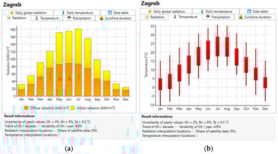
Figure 3.
Climate conditions for Zagreb: (a) temperature, (b) solar radiation.
Experimental model was built, as shown in Figure 4, with an outer width of 149.7 cm, and a height of 258.7 cm. The glass layers, argon, air cavity, sun blinds and frame parameters are listed in Table 1, including dimensions, solar factors, and heat capacity along with emissivity-, reflectivity-, and absorption coefficients.
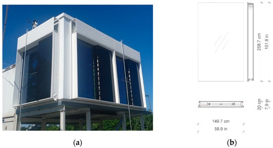
Figure 4.
Experimental model: (a) test box, (b) façade element dimensions.

Table 1.
Material properties used in the experimental test box and the mathematical model.
For the numerical analysis, various measurements were taken from the site during 2020 and 2021, which can be divided into three categories: climate conditions, model characteristics, and façade behavior. Climate conditions were measured by weather station, captured in Figure 4a, which measured air temperature, relative humidity of the outer air, atmospheric pressure, global radiation, wind speed and direction. The necessary climate conditions encompassed global solar radiation, which was later divided into direct, diffuse, reflected, and extraterrestrial radiation for the calculations. Model characteristics included the location coordinates (time zone), dimensions of the facade, the orientation of the sample model, as well as optical properties of the glass panes. Façade behavior was determined through measuring probes placed on the façade, as shown in Figure 5, where temperature sensors (Tx), relative humidity sensors (Hx), strain gauge sensors (Sx), sensors for measuring differential pressure (P1-ΔPGI P2-ΔPGA) are shown. PGA is the differential pressure between surrounding atmospheric pressure and gap pressure, while PGI is the differential pressure between internal and gap pressure, and Dx is the glass deflection measurement point.
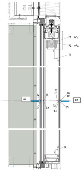
Figure 5.
Measuring probe locations in the façade element.
Data regarding physical properties (temperatures of the internal, middle, and external glass, air cavity, and interior temperature) and structural model characteristics (glass deflection, stresses, and air cavity pressure) were directly measured on-site, as shown in Figure 6.
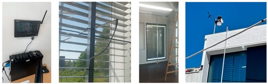
Figure 6.
Measuring devices on-site.
2.2. Mathematical Model
The mathematical model of the CCF was developed using Visual Basic/Visual Studio 2017 programming software, consisting of over 150 variables regarding properties of the façade elements and more than 100 formulae. This comprehensive model facilitates the calculations of energy flows within the CCF and between the CCF and its surroundings. It takes into account numerous physical properties of the façade elements and meteorological data. The model allows for temperature calculation considering various compositions of glazing, sunshade, and frame properties. Different locations are defined using meteorological data imported into the model via the Meteonorm 8.0 Software. Façade panel orientation, tilt angle, and environment albedo are also considered in the calculations.
The model considers all the relevant energy flows, which are further described in the subsequent chapters (Table 2, Figure 7). It comprehensively analyses three main types of energy transfers—radiative, convective, and conductive—as well as energy gains from solar radiation. Imported meteorological data with one-minute precision set the maximal time step for the calculation, ensuring accurate and detailed analysis.
2.3. Heat Transfer in CCF
Energy loss through CCF occurs through all three types of heat transfer—radiation, convection, and conduction (Figure 7). Among these, radiative and convective heat transfers are the most representative, while conductive heat transfer is nearly negligible [18].
Understanding heat gain, transfer, and the amount of energy in CCF is crucial, as it directly influences the temperature of each element in the façade. The simultaneous processes occurring inside the façade, such as glass deflection, gas pressure, and air exchange of the cavity, primarily depend on temperature [7]. Therefore, the thermal model of the façade forms the foundation of the entire physical and mathematical model describing the façades’ behavior.
Table 2.
Energy flows observed in one time-step.
Table 2.
Energy flows observed in one time-step.
| No. | Elements | Energy Transfer Type | |
|---|---|---|---|
| 1 | Interior | Inner glass | Convective, Radiative |
| 2 | Inner glass | Air gap | Convective |
| 3 | Inner glass | Sunshade | Radiative |
| 4 | Sunshade | Air gap | Convective |
| 5 | Sunshade | Inner glass | Radiative |
| 6 | Sunshade | Middle glass | Radiative |
| 7 | Inner glass | Middle glass | Conductive (by an air gap) |
| 8 | Middle glass | Outer glass | Radiative |
| 9 | Middle glass | Outer glass | Conductive (by argon layer) |
| 10 | Outer glass | Surrounding | Convective, Radiative |
| 11 | Interior | Façade frame | Convective, Radiative |
| 12 | Façade frame | Air gap | Convective, Radiative |
| 13 | Façade frame | Surrounding | Convective, Radiative, Conductive |
| 14 | Solar radiation | Outer glass | Solar gain |
| 15 | Solar radiation | Middle glass | Solar gain (transmitted) |
| 16 | Solar radiation | Sunshade | Solar gain (transmitted) |
| 17 | Solar radiation | Inner glass | Solar gain (transmitted) |
| 18 | Middle glass | Outer glass | Solar gain (reflected) |
| 19 | Sun blinds | Middle glass | Solar gain (reflected) |
| 20 | Solar radiation | Façade frame | Solar gain |

Figure 7.
Heat transfer scheme in a radiative, convective, and conductive manner. The numbers represent energy transfer listed in Table 2.
Figure 7.
Heat transfer scheme in a radiative, convective, and conductive manner. The numbers represent energy transfer listed in Table 2.

2.4. Radiative Heat Transfer
Heat transfer by radiation in IGU predominantly occurs between the glass panels and their surroundings. The inner surfaces of the glass panels are coated with low emissivity coatings, reducing heat transfer by radiation by up to 50 times [19]. On the other hand, the outer surfaces of the IGU are of regular emissivity, making radiative heat transfer most significant at the outer surfaces of the IGU, specifically between the IGU and its surroundings [20]. Radiative heat transfer also occurs between the sun blinds inside the cavity and the glass surfaces. The amount of solar energy absorbed in the sunshade slats depends on various factors, including solar radiation, slat angle, solar azimuth, height, and surface reflectance [21,22]. Since the sunshade serves as an opaque barrier in the façade, it absorbs most of the solar radiation, leading to the excessive temperatures up to 90 °C. The blinds’ slat surface is usually made of aluminium or a polymer coating with high emissivity, which results in a substantial amount of radiative heat transfer between the blinds and the surrounding glass, as illustrated in Figure 8b [22]. In Figure 8c,d, positive values represent heat transfer direction from interior to exterior, and negative ones the other way. Both sets of data have the highest values between 02 p.m. and 06 p.m. when there are the highest temperatures inside the CCF.
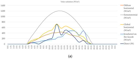
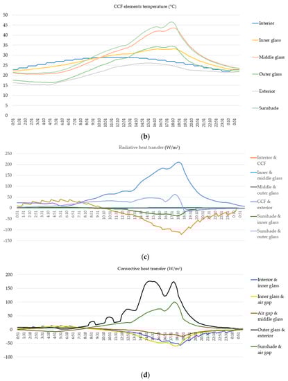
Figure 8.
Generated data for western orientation on 16 July in Zagreb; (a) for solar radiation (W/m2), (b) CCF elements temperatures (°C), (c) radiative heat transfer (W), and (d) convective heat transfer (W).
Radiative heat transfer between CCF and the surrounding air is the most significant. While the sunshade becomes the hottest element in the façade, radiative heat transfer to both the inner and outer glass is reduced. This reduction is due to the smaller temperature difference between the sunshade and the middle glass, as well as the presence of a low-emissivity coating on the outer surface of the inner glass. The radiative heat transfer from a body can be written mathematically using the Stefan-Boltzmann Law (Formula (1)) [23]:
wherein P is the radiative heat transfer rate (W), ε is surface emissivity (-), σ is the Stefan–Boltzmann constant 5.670374419...×10−8 Wm−2 K−4, A is the surface area of the body (m2), and T is the absolute temperature of the body (K).
Formula (2) calculates the net radiative heat transfer rate P between the body and its surroundings, considering the temperature difference to the fourth power, wherein T0 is the absolute temperature of the ambiance (K). During the day, as the body’s temperature T increases compared to the ambient temperature T0, the radiative heat transfer rate P will increase accordingly. Conversely, during the night, when the body’s temperature T is lower than the ambient temperature T0, the radiative heat transfer rate P will be negative, indicating that heat is being transferred from the surroundings to the body.
The transfer between two radiating bodies can be expressed using Formula (3) [20]:
In radiative heat transfer, energy is transferred between bodies or surroundings through infrared radiation. The radiative heat transfer rate P (W) between two bodies is calculated using Formula (3), where ε1 is the surface emissivity of the first body, and ε2 is the surface emissivity of the second body. It is important to note that radiative heat transfers occur only between solid bodies, as air mainly consists of oxygen and nitrogen, which do not absorb infrared radiation [24,25].
The mathematical model accounts for various radiative heat transfers between different components of the CCF. These include heat transfers between interior and inner glass, inner and middle glass (when the sunshade is opened), inner glass and the sunshade, sunshade and the middle glass, middle and outer glass, and outer glass and surrounding, as depicted in Figure 8c.
2.5. Convective Heat Transfer
Convective heat transfer includes energy transfer between solids and fluids (Figure 7). In this case, the fluid comprises inner air, outer air, and air inside the cavity, while solids are glass panels, façade frames, and sunshade slats. As the temperature difference between the solid surfaces and the surrounding air increases, a greater amount of air circulation occurs, leading to increased convection and heat transfer. Several factors influence convective heat transfer in this scenario. The properties of the fluid, such as conductive heat transfer coefficient, viscosity (cinematic and dynamic), pressure, heat capacity, temperature, and airspeed, play a crucial role. Similarly, the influencing properties of the solid elements are their temperature, size, and inclination. Convective heat transfer is characterized by Nusselt, Reynolds, Grashof, and Prandtl numbers, which are dimensionless values [26]. Newton’s law of cooling is expressed by Equation (4) used for both natural and forced convective heat transfer [27]:
where P is the rate of heat transfer between the fluid and the surface (W), A is the area of the surface in contact with the fluid, (m2), ΔT is the temperature difference between the fluid and the solid surface (K), and h is the convective heat transfer coefficient, (W/m2K). The convective heat transfer coefficient, h is calculated using Equation (5), including all the mentioned influencing factors [28].
wherein D is the characteristic height of the surface (m). Nusselt’s number Nu is calculated from the Grashof, Prandtl, Rayleigh, and Reynolds numbers. Grashof number Gr can be expressed using Formula (6):
where D is the characteristic height of the surface (m), ρ is air density (kg/m3), g is gravitational constant (m/s2), ΔT is temperature difference (K), µ is air dynamic viscosity, and Tair is absolute air temperature (K). The characteristic length depends on the tilt of the surface for vertical transfer D (height of the surface), and for horizontal surface, the characteristic length is defined using Equation (7).
where h is the height (m), and w is the width of the surface (m). Prandtl number Pr is calculated by the following Formula (8):
where Cp (J/(kg K)) is air-specific heat capacity, k (W/mK) is air thermal conductivity. Rayleigh number (Ra) can be written as Formula (9). For Rayleigh number values under 107, Nusselt numbers (Nu) are calculated using Formula (10), and for Rayleigh number values above 107, Nusselt numbers are calculated using Formula (11).
For forced convection, the Reynolds number (Re) is included, and the air film temperature is given as the average temperature between the surface and air (T1 + T2)/2, where v is wind or airspeed like shown in Formula (12).
Nusselt number (Nu) for forced convection depends on the Reynolds number, as shown in the following Equations (13) and (14):
Accounted convective natural heat transfers in the model are between (1) interior and inner glass, (2) inner glass and air gap, (3) air gap and middle glass, (4) sunshade and airgap, and (5) façade frame and air gap. For airspeed > 1 m/s, convective heat transfer between the outer glass and the exterior is calculated as forced convection, as shown in Figure 8d.
2.6. Conductive Heat Transfer
In the glazed elements of the building envelope, heat is primarily transferred by radiation and convection. Conduction occurs in thin glass panes, which provide almost non-existent heat transfer resistance (Table 3). An Insulation Glass Unit (IGU) is filled with an inert gas like argon, krypton, or xenon [29]. In thicker gas layers, convection can take place due to the temperature difference between the inner and outer glass and gas buoyancy [30]. However, in very thin layers of inert gas, convection is not possible, and heat transfer is primarily conductive (Figure 9). As a result, the inert gas layer represents the greatest conductive heat transfer resistance in the IGU [20].
Table 3.
Conductive heat transfer resistance of insulated glass unit components.
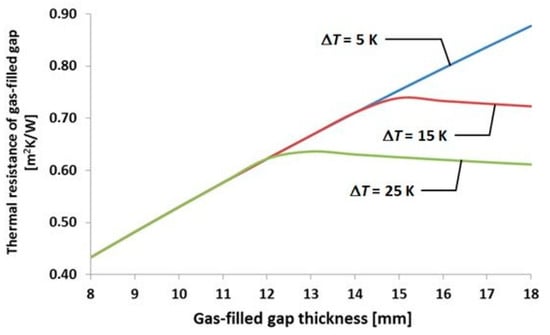
Figure 9.
Heat transfer through the argon layer depending on the thickness of the gas layer and glass pane temperature difference [31].
The width of the cavity and the temperature difference of elements around and inside the cavity allow for a complex airflow pattern to develop. To understand and measure such type of heat transfer, computational fluid dynamics (CFD) approach is required [18]. The heat transfer processes inside the CCF depend on ever-changing meteorological conditions such as air temperature, solar radiation, and wind speed. A very precise, iterative approach of one-minute time frame was used for meteorological data and heat transfer calculation, making the number of calculations numerous. Due to the complexity of the CFD approach, heat transfer through the air cavity in the CCF was simplified and observed as conductive.
2.7. Solar Radiation
For calculations of solar radiation, several pieces of information were required, including location data (local time zone, time zone, and geographical longitude and latitude). Atmospheric conditions at solar time, time equation, and time shift were accounted for using the date and local time. Climatic conditions obtained from Meteonorm software included solar azimuth, solar height (zenith), from which the declination of the sun, the angular incidence of the sun from the local meridian, and deviation of the earth’s orbit were calculated. Relevant input data describing the façade’s properties for further calculations included the inclination and azimuth of the façade surface. With this data, the angle of incidence of the sun on the surface can be calculated (Formula (15)).
wherein θsol;ic (°) is the angle of incidence of the sun onto the façade element surface, δ (°) is the Sun declination, φw (°) is geographic longitude, βic (°) is inclination of the façade element surface, γic (°) azimuth of the façade element surface, and ω is angular incidence of the Sun from the local meridian (°).
Global solar irradiance was divided into separate values, including direct solar irradiance (Formula (16)), diffuse solar irradiance (Formula (17)), albedo irradiance from the ground (Formula (18)), and circumsolar irradiance (Formula (19)). Each component’s quantity depends on various factors, such as weather conditions and the time of the day. Constants like Perez numbers were used to calculate the radiation on the inclined surface. Additionally, the clearness parameter, air mass, and sky brightness parameter were calculated using values of the direct and diffuse radiation onto the horizontal surface, the height of the Sun, the angle of incidence of the Sun onto the surface, zenith angle, and extraterrestrial irradiance [32,33,34].
where Idir (W/m2) is the direct radiation onto the surface of inclination βic (°), Gsol; dir (W/m2) is the direct radiation onto the horizontal surface and θsol;ic is the angle of incidence of the Sun onto the façade element surface (°). Diffuse solar irradiance is expressed by the following Formula (17):
where Idif (W/m2) is the diffuse radiation onto the surface of inclination βic, while F1 and F2 are Perez numbers, and a and b are auxiliary Perez factors, all dimensionless values. Diffuse solar irradiance on the inclined surface due to ground reflection Idif;grnd (W/m2) can be written mathematically using Formula (18):
where Gsol;dir (W/m2) is the direct radiation onto the horizontal surface, Gsol; dif (W/m2) is diffuse radiation onto the horizontal surface, αsol (°) is the sun height, and ρsol,grnd (-) is the albedo, whose value depends on the ground surface cover. Circumsolar irradiance is calculated by Formula (19):
Total direct solar irradiance onto the inclined surface Idir;tot (W/m2) is a sum of a direct Idir and circumsolar irradiance Icircum, which can be expressed by Formula (20):
The total diffuse solar irradiance onto the inclined surface Idif;tot (W/m2) is the sum of the diffuse and reflected ground irradiance (ground albedo). However, circumsolar irradiance should be subtracted from the total diffuse radiation, as written in Formula (21).
Finally, the total solar irradiance on the unshaded inclined surface is the sum of the total direct and total diffuse irradiance onto the inclined surface as shown in Formula (22).
The last factor influencing total solar radiation on the inclined surface is the impact of the sunshade, where shaded parts of the façade lack direct radiation compared to the rest of the façade element [35,36,37,38]. Figure 8a shows different segments of global solar radiation—direct, diffuse horizontal, and extraterrestrial, along with the global horizontal irradiation as well as its part irradiated onto the façade [33].
2.8. Glazing Properties
Solar heat gain in the CCF elements depends primarily on the glazing properties and the thermal properties of the sun shading [18]. Although the sunshade is the main source of heat in the CCF, solar energy reaching the sunshade passes through one or two layers of glass. The choice of glazing properties, therefore, plays a greater role in solar gain control. The most relevant glazing properties include absorptance, reflectance, energy transmittance, and emissivity [39]. The mentioned characteristics were included in the model for each glass panel (three panels) and each side of the glass panel (six sides).
Absorptance represents a ratio of incident solar energy absorbed in the glass panel, reflectance is the ratio of reflected solar energy, transmittance ratio of the solar energy passing through the glazing and emissivity is the ratio of radiated energy compared to perfect emitter (blackbody).
2.9. CCF Elements Temperature
When the basic energy flows in the façade are recognized, the amount of energy in each component can be calculated. Known properties of the used materials, such as mass and specific heat capacity, allow for the determination of temperature. For the calculation of temperature, the specific heat formula (Formula (23)) is used [40].
wherein Q (J) is the amount of energy in the component, c (J/kgK) is the specific heat capacity, and m (kg) is the mass of the component. The temperature was calculated for inner glass, air inside the cavity, sunshade slats, middle glass, outer glass, and façade frame (top, bottom, and sides), while the temperature of the argon layer was approximated as the arithmetic mean of the surrounding glass temperatures due to its very small thickness.
3. Results
For the validation of the thermal model of CCF, measured and calculated temperatures of the façade elements were compared. Measured data on-site included outer and inner air temperature, inner, middle, and outer glass temperature, and air gap temperature during winter southern orientation (Figure 10), winter western orientation (Figure 11), summer southern orientation (Figure 12), and summer western orientation (Figure 13). Additional meteorological data measured on site were wind speed, air pressure, and global solar radiation. Since the solar radiation in the model was calculated from direct and diffuse components, their ratio was estimated for the need of model validation.
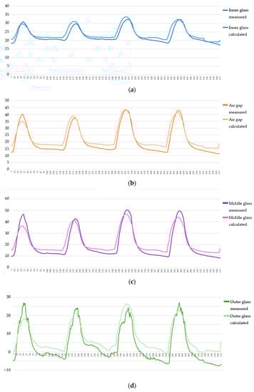
Figure 10.
Glazing and air gap temperatures comparison between the measured and calculated values for 3–6 January. Southern orientation for (a) inner glass, (b) air gap, (c) middle glass, and (d) outer glass. Temperatures are expressed in (°C).
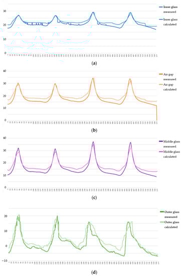
Figure 11.
Glazing and air gap temperatures comparison between measured and calculated values for 3–6 January. Western orientation for (a) inner glass, (b) air gap, (c) middle glass, and (d) outer glass. Temperatures are expressed in (°C).
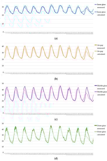
Figure 12.
Glazing and air gap temperatures comparison between measured and calculated values for 18–27 June. Southern orientation for (a) inner glass, (b) air gap, (c) middle glass, and (d) outer glass. Temperatures are expressed in (°C).
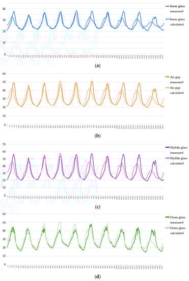
Figure 13.
Glazing and air gap temperatures comparison between measured and calculated values for 18–27 June. Western orientation for (a) inner glass, (b) air gap, (c) middle glass, and (d) outer glass. Temperatures are expressed in (°C).
Since only global solar radiation was measured on site, ratio between direct and diffuse solar radiation was approximated for each measurement data set that was to be validated. Measured data were imported into the model, and the results were compared for various seasons and orientations. The difference in the results was up to 3 °C which was accepted as a satisfying result. Occasional differences greater than 5 °C were attributed to the poor estimate of direct and diffuse solar radiation ratio. Approximated ratio between direct and diffuse solar radiation which gave the most desirable results, was taken as a referent one for all the days in the data set. During the period 3–6 January, the ratio between direct and diffuse solar radiation appeared to have varied greatly, what can be particularly observed during 5 and 6 January, western orientation, as shown in Figure 11d.
The results shown are for winter and summer periods and the southern and western orientations.
4. Discussion
The article presents the results of experimental and numerical simulations of the thermal behavior of passively maintained closed cavity façades during 2020–2023. Experimental model was placed in Zagreb, where measurements described in this paper were taken during 3–6 January and 18–27 June. Using simplified but unconventional methods, numerous formulae and variables, and software describing the thermal behavior of the CCF were conducted, which can be applicable to any other location, climatic conditions, and the façade’s orientation, dictating necessary façade element’s properties, respecting European standards.
Many studies in the last decade have been performed on real buildings, by monitoring parameters for longer periods on multilayered and close cavity façades. While several researchers were concerned with lowering the physical conditions of the façade such as Wüest and Luible, in 2016, who compared different glass and interspace thicknesses lowering excessive temperatures of argon from 39 °C to 34 °C only by changing the outer glass thickness. Interspace with sun blinds lowered the temperature from a non-ventilated cavity with 57 °C to 48 °C when ventilation was added [11]. Laverge, Schouwenaers, and Janssens proved in 2009, that mechanical ventilation will avoid condensation of the glass surfaces, but low airflow will not reduce excessive temperatures. They validated the thermal model of the sample by the good agreement of the new type of façade element with the European and American standard programs. Values of measured data and standard programs have the most differences in higher solar radiation, while during lower temperature rates, the differences are almost non-existing [1]. Van den Bossche and Lori made it a step further when examining Laverge’s model, creating a software which monitors actively maintained close cavity façades. Maximum error for the peak values showed in their software was in range between 5–10% [7].
Although the field of closed cavity façades is new, and there are a few researchers exploring and improving the design of CCF, the sustainability of CCF has never reached passive maintenance before. According to EN1991-1-4, a skin is considered impermeable when its permeability is lower than 0.1% of the skin surface, this façade is not fully closed. The thin capillary and outer IGU layers enable the passive functioning of the facade, using no external energy. The thermal behavior of the façade is validated both by measurements on-site and calculations in software created for this research. Maximum efficiency of the naturally ventilated façade performance is achieved during the hottest hours of the day, between 02 p.m. and 06 p.m. (Figure 8a), when the solar radiation has the highest value. Although numerous variables were taken into account, insufficient data regarding separate measuring direct and diffuse solar radiation, during cloudy days showed greater differences (5 and 6 January, western orientation, Figure 11d). Nevertheless, a comparison between the calculated and measured values of the layers’ temperatures shows the satisfying value difference of up to 3 °C, which is between 5–10% for peak values.
5. Conclusions and Future Work
This paper has focused on the mathematical model of the closed cavity façade and its validation through an experimental model. The primary advantage of this tool lies in its simplicity and ease of iteration, allowing users to enter data regarding the physical properties of the façade and verify outputs within the information regarding location, building typology, climate conditions etc. Another value lies in possible improvements to the software, introducing more complicated calculations such as FEM analysis, providing even greater accuracy.
The focus of the presented model is on thermal behavior since it represents a base for further research on the close cavity façades in terms of structural and hygric behavior. For the structural behavior, crucial is the exchange of the air between the surroundings and the façades interspace, inflating and deflating the air volume inside the cavity. With the outer air supply, moisture will be driven into the cavity as well, for which desiccant should be introduced inside the cavity to avoid excessive humidity. It is worth considering that in the future, this approach could be integrated with other engineering calculations, particularly concerning structural and hygric performance. Calculating the service life of the desiccant ensures that during this period, there will be no condensation in the cavity, i.e., the façade will fulfill its purpose. In this way, the service life expectancy can be calculated for the desiccants and, therefore, for the façades’ element.
Author Contributions
Conceptualization, Z.V. and M.B.; methodology, Z.V., M.B., M.N.M. and J.G.; software, M.B.; validation, M.B. and M.N.M.; formal analysis, Z.V. and M.B.; investigation, Z.V., M.B., M.N.M. and J.G.; resources, Z.V. and J.G.; data curation, M.B.; writing—original draft preparation, Z.V., M.B., M.N.M. and J.G.; writing—review and editing, Z.V., M.B., M.N.M. and J.G.; visualization, M.B. and M.N.M.; supervision, Z.V.; project administration, Z.V., M.B., M.N.M. and J.G.; funding acquisition, Z.V. and J.G. All authors have read and agreed to the published version of the manuscript.
Funding
The research was conducted as part of the “Development of a double façade with a hermetically sealed cavity H-CCF” project funded by the European Union from the European Regional Development Fund (Grant Number KK.01.2.1.02.0218).
Data Availability Statement
The data presented in this study form an integral part of the innovative concept design and are essential for the protection of our intellectual property and ideas. The data that support the findings of this study are available from the corresponding author, M.B., upon reasonable request.
Acknowledgments
The authors would like to thank KFK company for good collaboration in the whole “Development of a double façade with a hermetically sealed cavity H-CCF” project and for providing a test model with measurements on-site.
Conflicts of Interest
The authors declare no conflict of interest.
Nomenclature
| Symbol | Definition | Unit/ Constant Value |
| A | surface area of the body | [m2] |
| c | specific heat capacity | [J/(kg K)] |
| Cp | air-specific heat capacity | [J/(kg K)] |
| D | characteristic length | [-] |
| F1, F2 | Perez factor | [-] |
| g | gravitational constant | 9.81 [m/s2] |
| Gr | Grashof number | [-] |
| Gsol;dif | diffuse radiation onto the horizontal surface | [W/m2] |
| Gsol;dir | direct radiation onto the horizontal surface | [W/m2] |
| h | convective heat transfer coefficient | [W/(m2K)] |
| Icircum | Circumsolar irradiance | [W/m2] |
| Idif | diffuse radiation onto inclined surface | [W/m2] |
| Idif;tot | Total diffuse solar irradiance onto the inclined surface | [W/m2] |
| Idif;grnd | Diffuse solar irradiance on the inclined surface due to ground reflection | [W/m2] |
| Idir | direct radiation onto inclined surface | [W/m2] |
| Idir;tot | Total direct solar irradiance onto the inclined surface | [W/m2] |
| Itot | total solar irradiance | [W/m2] |
| k | air thermal conductivity | [W/(mK)] |
| m | mass of the component | [kg] |
| Nu | Nusselt number | [-] |
| P | radiative heat transfer rate | [W] |
| Pr | Prandtl number | [-] |
| Q | amount of energy in the component | [J] |
| Ra | Rayleigh number | [-] |
| Re | Reynolds number | [-] |
| T | absolute temperature of the body | [K] |
| T0 | ambient temperature | [K] |
| v | wind or airspeed | [m/s] |
| w | width | [m] |
| Greek symbols | ||
| µ | air dynamic viscosity | [kg/(m·s)] |
| βic | inclination of the façade element surface | [°] |
| γic | azimuth of the façade element surface | [°] |
| δ | Sun declination | [°] |
| ε | surface emissivity | [-] |
| θsol; ic | angle of incidence of the sun onto the façade element surface | [°] |
| ρ | air density | [kg/m3] |
| ρsol,grnd | albedo | [-] |
| σ | azimuth angle | 5.670374419...×10−8 [Wm−2K−4] |
| φw | geographic longitude | [°] |
| ω | angular incidence of the Sun from the local meridian | [°] |
References
- Laverge, J.; Schouwenaers, S.; Janssens, A. Overcoming condensation problems in a closed cavity double skin façade. In Proceedings of the Cold Climate HVAC 2009, Sisimiut, Greenland, 16–19 March 2009. [Google Scholar]
- GBD Magazine. Available online: https://gbdmagazine.com/closed-cavity-facades/ (accessed on 25 June 2023).
- Veršić, Z.; Nosil Mešić, M.; Binički, M.; Cvitković, I.; Petrac, D. A simulation of the physical characteristics of passively maintained closed cavity facades. Institue Technol. Res. 2023, 978, 11–14. [Google Scholar]
- Sdg 2. Transforming Our World: The 2030 Agenda for Sustainable Development. A/RES/70/1, 2015, United Nations. 2021. Available online: https://sdgs.un.org/publications/transforming-our-world-2030-agenda-sustainable-development-17981 (accessed on 15 July 2023).
- Huveners EM, P.; Van Herwijnen, F.; Soetens, F. Load sharing in insulated double glass units. Heron 2003, 48, 99–122. [Google Scholar]
- Laverge, J.; Schouwenaars, S.; Steeman, M.; Janssens, A.; Van Den Bossche, N. Condensation in a closed cavity double skin facade: A model for risk assessment. In Proceedings of the International Conference on Building Envelope Systems and Technologies (ICBEST 2010), Vancouver, BC, Canada, 27–30 June 2010. [Google Scholar]
- Van Den Bossche, N.; Van Den Brande, K.; De Bleecker, H.; Lori, G. Validation of a coupled pressure-equalization-thermal-mechanical model to study double-skin facades. E3S Web Conf. 2020, 172, 1–8. [Google Scholar] [CrossRef]
- Lori, G.; Van Den Brande, K.; Van Den Bossche, N.; De Bleecker, H. A simple numerical tool for superimposition of climatic load and wind load in Closed Cavity Facades: Importance of a coupled PE-thermal-mechanical model. Glas. Struct. Eng. 2022, 7, 487–506. [Google Scholar] [CrossRef]
- Lori, G.; Van Den Brande, K.; Van Den Bossche, N.; De Bleecker, H. Experimental validation of a numerical model for closed cavity façade glass structural calculation under dynamic cavity temperature, dry air flow and wind loads effects. Glas. Struct. Eng. 2022, 7, 523–545. [Google Scholar] [CrossRef]
- Lori, G.; Van Den Brande, K.; Van Den Bossche, N.; De Bleecker, H. Experimental and numerical assessment of permeability functions in closed cavity façades. Glas. Struct. Eng. 2022, 7, 507–521. [Google Scholar] [CrossRef]
- Wüest, T.; Luible, A. Thermal induced climatic loads of insulated glazed units in energy efficient facades. In Proceedings of the Challenging Glass 5 Conference on Architectural and Structural Applications of Glass, CGC 2016; Ghent University: Ghent, Belgium, 2016; pp. 261–270. [Google Scholar]
- Kozłowski, M.; Respondek, Z.; Wiśniowski, M.; Cornik, D.; Zemła, K. Experimental and Numerical Simulations of Climatic Loads in Insulating Glass Units by Controlled Change of Pressure in the Gap. Appl. Sci. 2023, 13, 1269. [Google Scholar] [CrossRef]
- Rashid, F.L.; Al-obaidi, M.A.; Dulaimi, A.; Mahmood, D.M.N. A Review of Recent Improvements, Developments, and Effects of Using Phase-Change Materials in Buildings to Store Thermal Energy. Designs 2023, 7, 90. [Google Scholar] [CrossRef]
- Rashid, F.L.; Al-gaheeshi, A.M.R.; Alhwayzee, M.; Ali, B.; Shah, N.A.; Chung, J.D. Mixed Convection in a Horizontal Channel—Cavity Arrangement with Different Heat Source Locations. Mathematics 2023, 11, 1428. [Google Scholar] [CrossRef]
- Rashid, F.L.; Hussein, A.K.; Malekshah, E.H.; Abderrahmane, A.; Guedri, K.; Younis, O. Review of Heat Transfer Analysis in Different Cavity Geometries with and without Nanofluids. Nanomaterials 2022, 12, 2481. [Google Scholar] [CrossRef]
- Gallo, P.; Romano, R. Adaptive Facades, Developed with Innovative Nanomaterials, for a Sustainable Architecture in the Mediterranean Area. Procedia Eng. 2017, 180, 1274–1283. [Google Scholar] [CrossRef]
- Pastori, S.; Mereu, R.; Mazzucchelli, E.S.; Passoni, S. Energy Performance Evaluation of a Ventilated Façade System through CFD Modeling and Comparison with International Standards. Energies 2021, 14, 193. [Google Scholar] [CrossRef]
- Jankovic, A.; Goia, F. Impact of double skin facade constructional features on heat transfer and fluid dynamic behaviour. Build. Environ. 2021, 196, 107796. [Google Scholar] [CrossRef]
- Jelle, B.P.; Kalnæs, S.E.; Gao, T. Low-Emissivity Materials for Building Applications: A State-of-the-Art Review and future research perspectives. Energy Build. 2015, 96, 329–356. [Google Scholar] [CrossRef]
- Maiorov, V.A. Heat transfer through a double-glazed window by radiation. IOP Conf. Ser. Mater. Sci. Eng. 2020, 939, 012048. [Google Scholar] [CrossRef]
- Iyi, D.; Hasan, R.; Penlington, R.; Underwood, C. Double skin façade: Modelling technique and influence of venetian blinds on the airflow and heat transfer. Appl. Therm. Eng. 2014, 71, 219–229. [Google Scholar] [CrossRef]
- Okada, T.; Ishige, R.; Ando, S. Analysis of thermal radiation properties of polyimide and polymeric materials based on ATR-IR spectroscopy. J. Photopolym. Sci. Technol. 2016, 29, 251–254. [Google Scholar] [CrossRef]
- Wellons, M. The Stefan-Boltzmann Law. In The Visual Dictionary of Photography; Bulb: Wooster, OH, USA, 2010. [Google Scholar]
- Hines, S. Greenhouse effect. In The Complete Guide to Climate Change; Routledge: London, UK, 2008. [Google Scholar] [CrossRef]
- Brown, F.E. Molecular and atomic weights. J. Chem. Educ. 1933, 10, 308–309. [Google Scholar] [CrossRef]
- Khalifa, A.J.N. Natural convective heat transfer coefficient—A review I. Isolated vertical and horizontal surfaces. Energy Convers. Manag. 2001, 42, 491–504. [Google Scholar] [CrossRef]
- O’Sullivan, C.T. Newton’s law of cooling—A critical assessment. Am. J. Phys. 1990, 58, 956–960. [Google Scholar] [CrossRef]
- Bright Hub Engineering. Available online: https://www.brighthubengineering.com/hvac/92660-natural-convection-heat-transfer-coefficient-estimation-calculations/?utm_content=cmp-true (accessed on 14 October 2022).
- Weir, G.; Muneer, T. Energy and environmental impact analysis of double-glazed windows. Energy Convers. Manag. 1998, 39, 243–256. [Google Scholar] [CrossRef]
- Respondek, Z. Influence of insulated glass units thickness and weight reduction on their functional properties. Open Eng. 2018, 8, 455–462. [Google Scholar] [CrossRef]
- Zoran, V.; Josip, G.; Marin, B.; Lucija, S. Factors in a Sustainability Assessment of a New Types of Closed Cavity Facades. MMM Int. J. Adv. Eng. Archit. Math. 2022, 16, 148–152. [Google Scholar]
- ISO 52016-1:2017; Energy Performance of Buildings—Energy Needs for Heating and Cooling; Internal Temperatures and Sensible and Latent Heat Loads—Part 1: Calculation Procedures. ISO: Geneva, Switzerland, 2017.
- ISO/TR 52010-2:2017; Energy performance of buildings—External climatic conditions—Part 2: Explanation and justification of ISO 52010-1. ISO: Geneva, Switzerland, 2017. Available online: https://www.iso.org/standard/67344.html (accessed on 15 July 2023).
- Focus on EPB standards. REHVA Eur. HVAC J. 2015, 52.
- Yang, D. Solar radiation on inclined surfaces: Corrections and benchmarks. Sol. Energy 2016, 136, 288–302. [Google Scholar] [CrossRef]
- Widén, J.; Munkhammar, J. Solar Radiation Theory, 1st ed.; Uppsala University: Uppsala, Sweden, 2019; ISBN 978-91-506-2760-2. [Google Scholar] [CrossRef]
- Perez, R.; Stewart, R.; Seals, R.; Guertin, T. The Development and Verification of the Perez Diffuse Radiation Model; Sandia National Laboratorie: Albuquerque, NM, USA; State University: Albany, NY, USA, 1988; p. 176.
- Thornsberry, C. Methicillin-resistant staphylococci. Clin. Lab. Med. 1989, 9, 255–267. [Google Scholar] [CrossRef] [PubMed]
- Pérez-Grande, I.; Meseguer, J.; Alonso, G. Influence of glass properties on the performance of double-glazed facades. Appl. Therm. Eng. 2005, 25, 3163–3175. [Google Scholar] [CrossRef]
- Walker, J.; Halliday, D.; Resnick, R. Fundamentals of Physics Halliday & Resnick, 10th ed.; Wiley: Hoboken, NJ, USA, 2014. [Google Scholar]


Disclaimer/Publisher’s Note: The statements, opinions and data contained in all publications are solely those of the individual author(s) and contributor(s) and not of MDPI and/or the editor(s). MDPI and/or the editor(s) disclaim responsibility for any injury to people or property resulting from any ideas, methods, instructions or products referred to in the content. |
© 2023 by the authors. Licensee MDPI, Basel, Switzerland. This article is an open access article distributed under the terms and conditions of the Creative Commons Attribution (CC BY) license (https://creativecommons.org/licenses/by/4.0/).