

Flexure Strengthening and Analysis Using CFRP Composite and Reactive Powder Concrete

 ,
,  ,
,
Abstract
:1. Introduction
2. Materials and Methods
2.1. Raw Material
2.2. Test Specimens and Methods
2.2.1. Test Plan
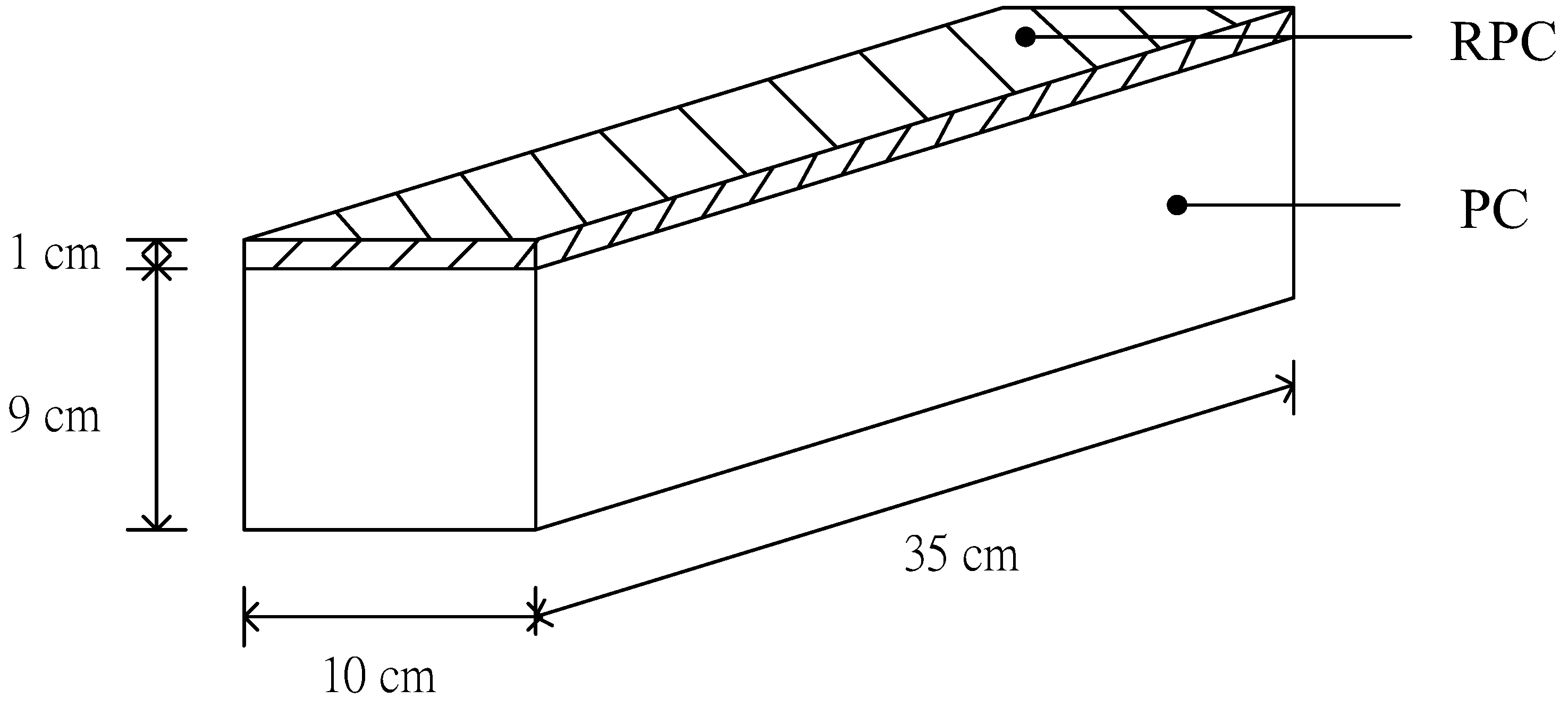
2.2.2. Fabrication of Concrete Samples Retrofitted with RPC or CFRP
- (1)
- Fabrication of concrete samples retrofitted with CFRP
- (2)
- Fabrication of concrete samples retrofitted with RPC
3. Results and Discussion
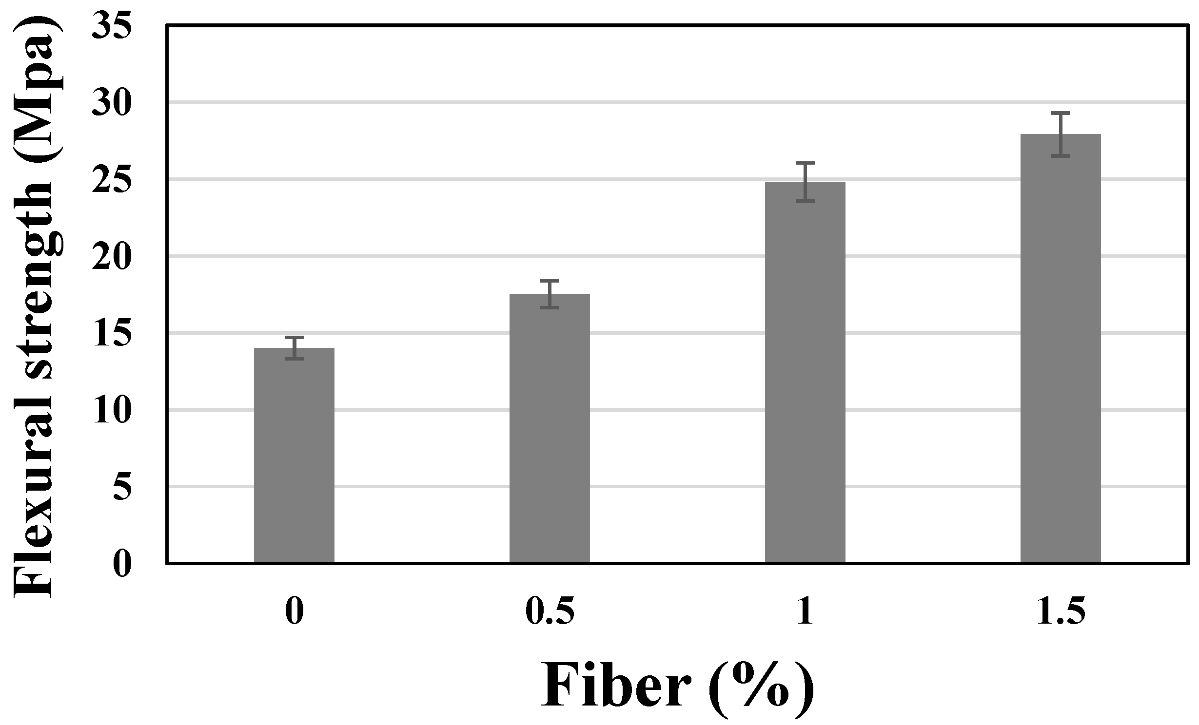
3.1. Flexural Strength of RPC
3.2. Concrete Beam Reinforcement
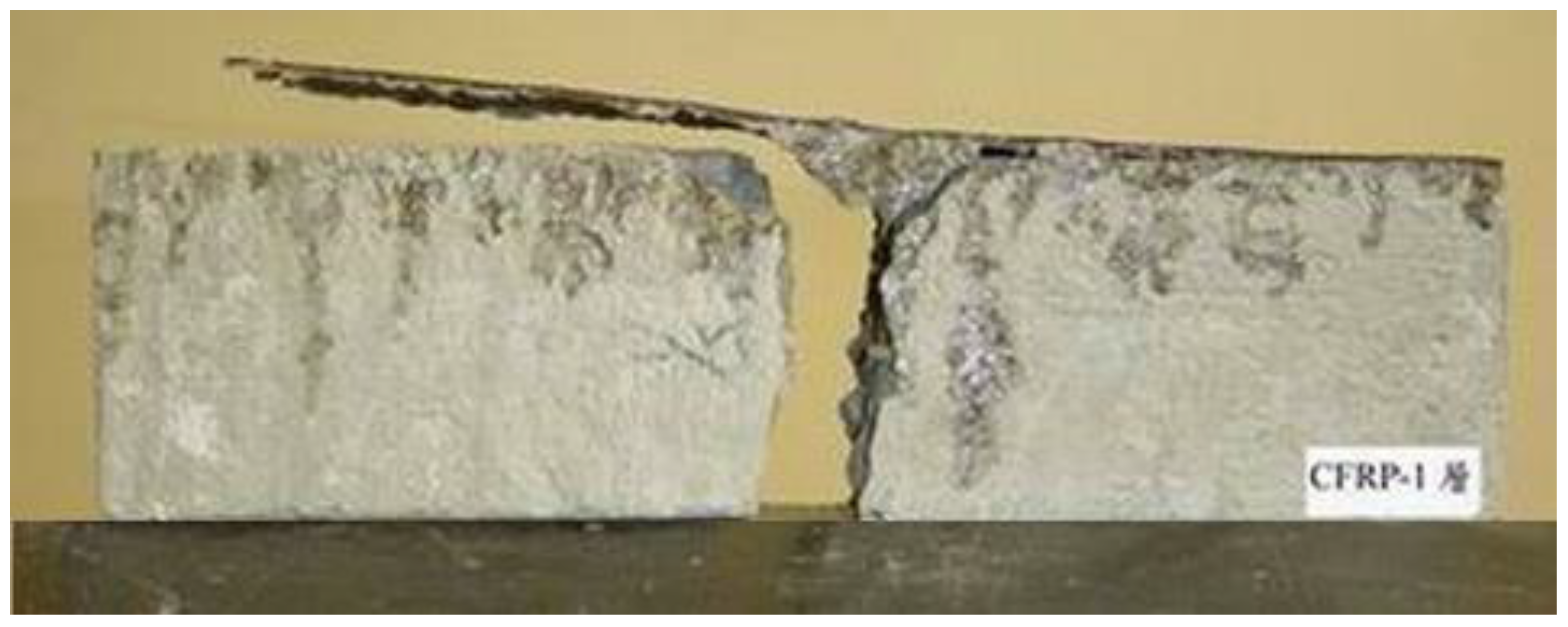
3.2.1. Concrete Beams Reinforced with CFRP
3.2.2. Concrete Beams Reinforced with RPC
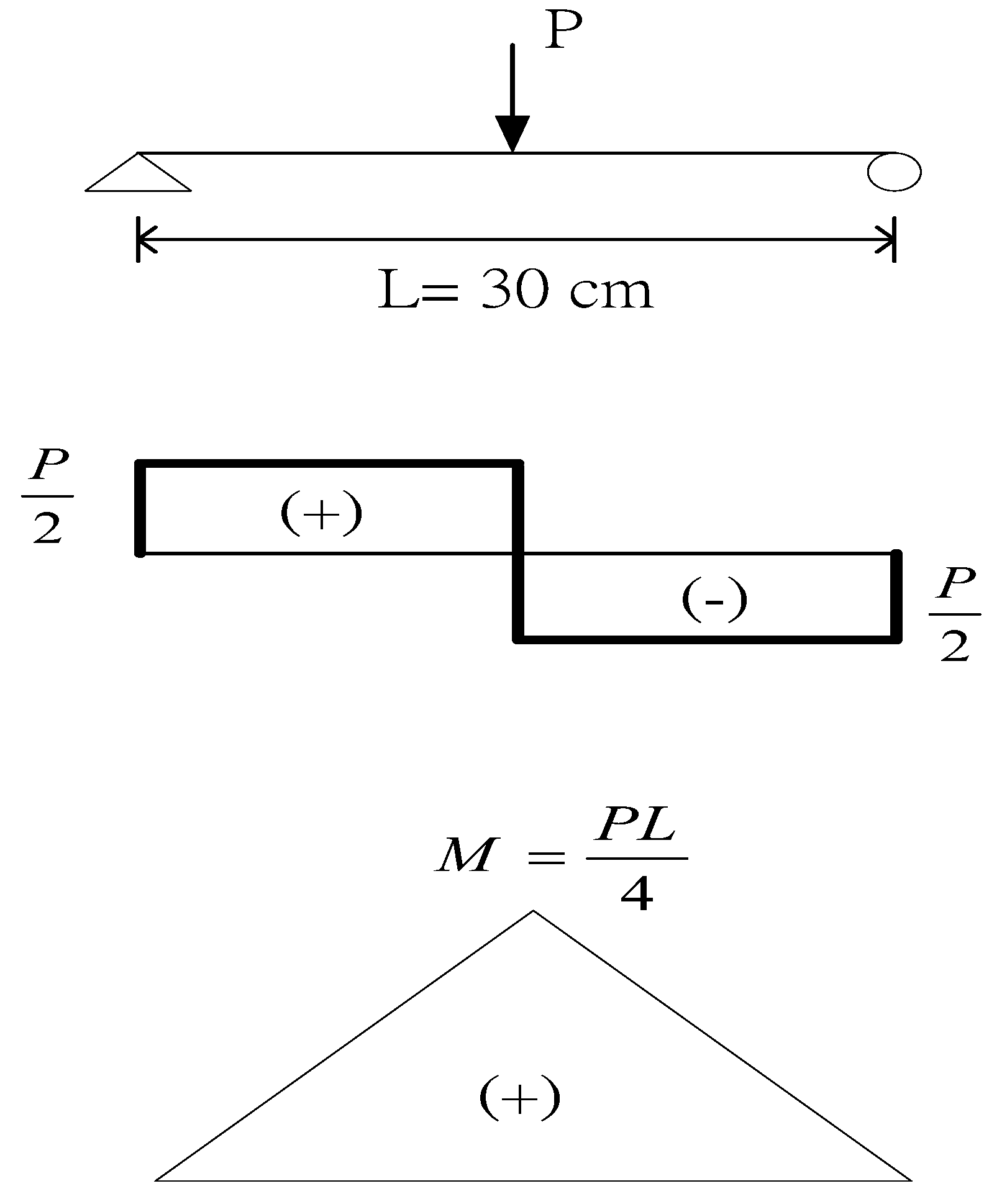
3.3. Theoretical Calculation and Analysis of Bending Strength of Reinforced PC Beams
3.3.1. Comparison of Experimental and Theoretical Values of PC Beams Reinforced with RPC
- PC beam: elastic modulus E1 = 2.41 × 10⁵ kg/cm2, compressive strength σ1 = 347 kgf/cm2, flexural strength σ2 = 53 kgf/cm2, oblique shear strength τ = 117 kgf/cm2
- RPC1: elastic modulus E2 = 3.01 × 10⁵ kg/cm2, flexural strength σ3 = 201 kgf/cm2
3.3.2. Comparison of Experimental and Theoretical Values of PC Beams Reinforced with CFRP
- PC beam: elastic modulus E1 = 2.41 × 10⁵ kg/cm2, compressive strength σ1 = 347 kgf/cm2, flexural strength σ2 = 53 kgf/cm2, oblique shear strength τ = 117 kgf/cm2
- CFRP1: elastic modulus E2 = 7.4 × 10⁵ kg/cm2, flexural strength σ3 = 7800 kgf/cm2, oblique shear strength τ = 100 kgf/cm2, thickness t = 0.3 mm.
- (1)
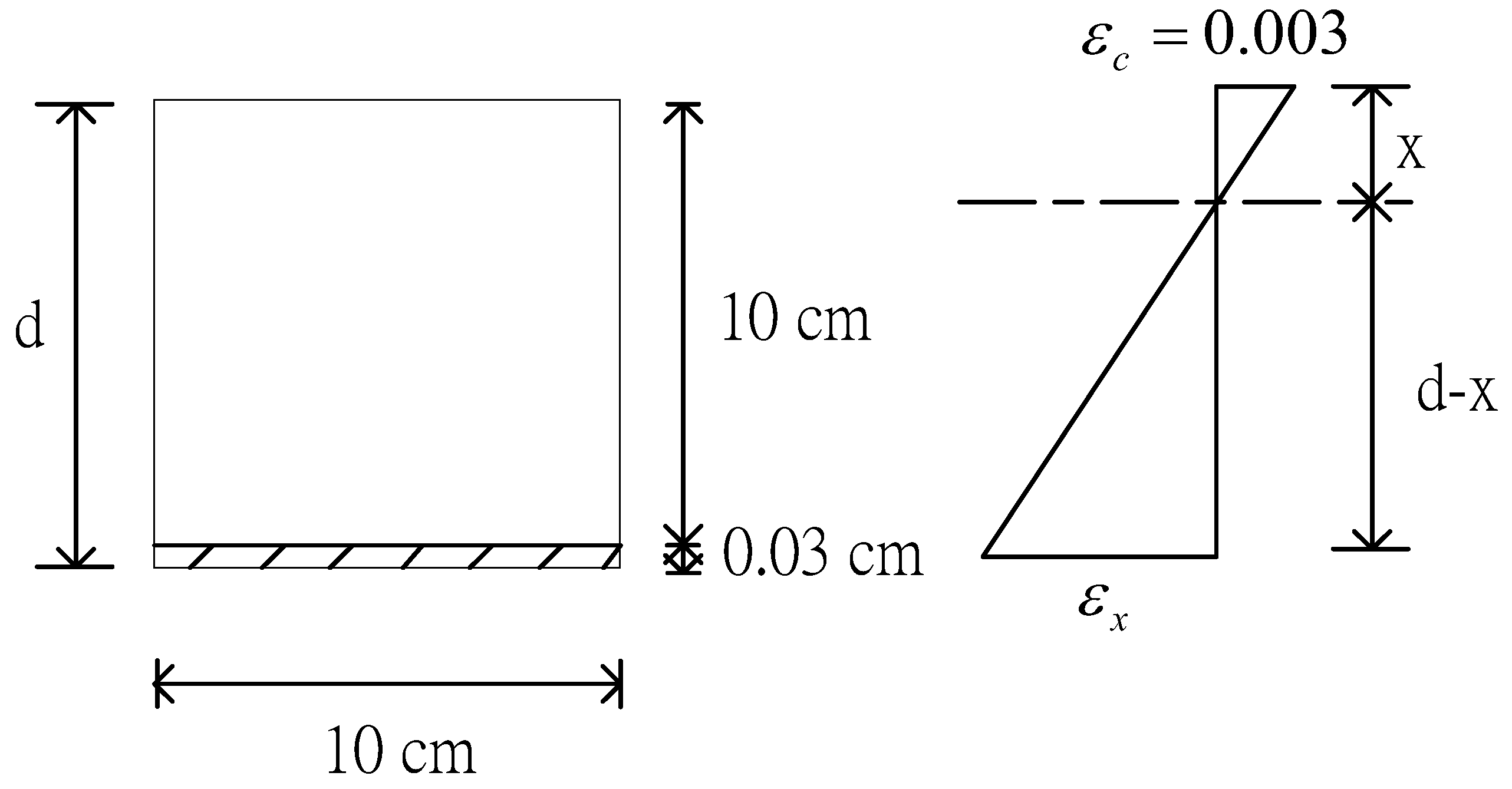
- Using the converted section method (shown in Figure 8) to calculate the internal stress of the composite beam is as follows:
- (2)
- The ultimate stress method (shown in Figure 9) calculates the internal stress of the composite beam:
4. Conclusions
- (1)
- According to the results of the bending test, the flexural strength of RPC concrete has a tendency to increase significantly with the increase of steel fiber content. When the steel fiber content increases to 1.5%, its flexural strength is about 2 times, so adding steel fiber can effectively improve the tensile strength and toughness of concrete.
- (2)
- The flexural strength of CFRP-reinforced concrete beam specimens can be increased by 67.3% with one layer of CFRP, 118.4% with two layers of CFRP, and 160.8% with three layers of CFRP. It shows that CFRP-reinforced concrete can obtain a good reinforcing effect, and the flexural strength is significantly improved with the increase of CFRP-reinforced layers.
- (3)
- The flexural strength of the concrete beam specimen reinforced with RPC increases significantly with the increase of steel fiber content and repair thickness. Among them, RPC reinforcement with a thickness of 1 cm and a steel fiber content of 1% is approximately equal to a layer of CFRP, and an RPC reinforcement with a thickness of 2 cm of 0.5% steel fiber is also approximately equal to a two-layer CFRP coating. The RPC reinforcement with a thickness of 2 cm and a steel fiber content of 1.0% is approximately equal to that of three layers of CFRP.
- (4)
- The RPC reinforcement can be used to analyze the internal stress of the beam using the conversion section method of material mechanics. The theoretical value and experimental value of the maximum failure load obtained can obtain similar results. Therefore, this method is suitable for evaluating the effectiveness of RPC-reinforced concrete beams.
- (5)
- Analyzing the internal stress with the conversion section method and ultimate stress method of material mechanics cannot correctly evaluate the effectiveness of CFRP-reinforced concrete beams.
- (6)
- Due to the high cost of experimental testing, future research directions could consider developing methods to accurately predict the behavior of unreinforced and strengthened composite beams.
Author Contributions
Funding
Data Availability Statement
Acknowledgments
Conflicts of Interest
Appendix A
Nomenclature
| n | elastic modulus ratio |
| E1 | elastic modulus of PC |
| E2 | elastic modulus of reinforcing material |
| b | width of beam rectangular section, mm |
| h | height of beam rectangular section, mm |
| h1 | height of PC beam section, mm |
| h2 | height of reinforcing material beam section, mm |
| y | distance from neutral axis to outer surface of beam, mm |
| σ1 | maximum compressive stress of PC |
| σ2 | maximum tensile stress of PC |
| σ3 | maximum tensile stress of reinforcing material |
| shear stress at the bonding interface | |
| x | depth of the equivalent rectangular stress block, mm |
| concrete strain | |
| strain of reinforcing material | |
| I | moment of inertia |
| bending moment of maximum compressive stress of PC | |
| bending moment of maximum tensile stress of PC | |
| bending moment of maximum tensile stress of reinforcing material | |
| As | total area of tensile reinforcement (CFRP), mm2 |
References
- Dugat, J.; Roux, N.; Bernier, G. Mechanical properties of reactive powder concretes. Mater. Struct. 1996, 29, 233–240. [Google Scholar] [CrossRef]
- Lee, M.; Chiu, C.; Wang, Y. The Study of Bond Strength and Bond Durability of Reactive Powder Concrete. J. ASTM Int. 2005, 2, 104–113. [Google Scholar] [CrossRef]
- Richard, P.; Cheyrezy, M. Composition of reactive powder concretes. Cem. Concr. Res. 1995, 25, 1501–1511. [Google Scholar] [CrossRef]
- Lee, M.; Wang, Y.; Chiu, C. A preliminary study of reactive powder concrete as a new repair material. Constr. Build. Mater. 2007, 21, 182–189. [Google Scholar] [CrossRef]
- Bonneau, O.; Lachemi, M.; Dallaire, E.; Dugat, J.; Aitcin, P.C. Mechanical Properties and Durability of Two Industrial Reactive Powder Concretes. ACI Mater. J. 1997, 94, 286–290. [Google Scholar]
- Graybeal, B.A. Compressive behavior of ultra-high-performance fiber-reinforced concrete. ACI Mater. J. 2007, 104, 146–152. [Google Scholar]
- Wu, Z.; Shi, C.; Khayat, K.H. Investigation of mechanical properties and shrinkage of ultra-high performance concrete: Influence of steel fiber content and shape. Compos. Part B Eng. 2019, 174, 107021. [Google Scholar] [CrossRef]
- Skazlic, M.; Bjegovic, D.; Serdar, M. Influence of test specimens’ geometry on compressive strength of ultra-high-performance concrete. In Proceedings of the 2nd International Symposium on Ultra-High-Performance Concrete 2008, Kassel, Germany, 5–7 March 2008; pp. 295–301. [Google Scholar]
- Magureanu, C.; Sosa, I.; Negrutiu, C.; Heghes, B. Mechanical properties and durability of ultra-high-performance concrete. ACI Mater J. 2012, 109, 177–183. [Google Scholar]
- Kang, S.T.; Choi, J.I.; Koh, K.T.; Lee, K.S.; Lee, B.Y. Hybrid effects of steel fiber and microfiber on the tensile behaviour of ultra-high-performance concrete. Compos. Struct. 2016, 145, 37–42. [Google Scholar] [CrossRef]
- Lee, M.; Huang, Y.; Kan, Y.; Wang, Y.; Chen, Y.; Kao, S. Experimental study on durability of CFRP-strengthened wood members. J. Mater. Res. Technol. 2023, 24, 3704–3716. [Google Scholar] [CrossRef]
- Qiang, X.; Chen, L.; Jiang, X. Experimental and theoretical study on flexural behavior of steel–concrete composite beams strengthened by CFRP plates with unbonded retrofit systems. Compos. Struct. 2023, 309, 116763. [Google Scholar] [CrossRef]
- Zhang, Y.; Duan, L.; Liu, H.; Lu, J.; Huo, Y. Experimental and numerical study on multi-impact performance of pre-damaged beams strengthened with CFRP. Eng. Struct. 2023, 285, 116034. [Google Scholar] [CrossRef]
- Guo, R.; Li, C.; Xian, G. Water absorption and long-term thermal and mechanical properties of carbon/glass hybrid rod for bridge cable. Eng. Struct. 2023, 274, 115176. [Google Scholar] [CrossRef]
- Huang, Y.; Lee, M.; Kan, Y.; Wang, W.; Wang, Y.; Pan, W.-B. Reinforced concrete beams retrofitted with UHPC or CFRP. Case Stud. Constr. Mater. 2022, 17, e01507. [Google Scholar] [CrossRef]
- Nguyen, D.L.; Ryu, G.S.; Koh, K.T.; Kim, D.J. Size and geometry dependent tensile behaviour of ultra-high-performance fiber-reinforced concrete. Compos. Part B-Eng. 2014, 58, 279–292. [Google Scholar] [CrossRef]
- Wang, W.; Huang, Y.; Lee, M.; Wang, Y.; Kan, Y.; Hsiao, Y.; Chang, H. Case study for ditch cover with ultra-high-performance concrete. Case Stud. Constr. Mater. 2022, 17, e01647. [Google Scholar] [CrossRef]
- Lee, M.; Wang, W.; Wang, Y.; Hsieh, Y.; Lin, Y. Mechanical Properties of High-Strength Pervious Concrete with Steel Fiber or Glass Fiber. Buildings 2022, 12, 620. [Google Scholar] [CrossRef]
- Kazemi, S.; Lubell, A. Influence of specimen size and fiber content on mechanical properties of ultra-high-performance fiber-reinforced concrete. ACI Mater. J. 2012, 109, 675–684. [Google Scholar]
- Elsayed, M.; Tayeh, B.A.; Elmaaty, M.A.; Aldahshoory, Y. Behaviour of RC columns strengthened with Ultra-High Performance Fiber Reinforced concrete (UHPFRC) under eccentric loading. J. Build. Eng. 2022, 47, 103857. [Google Scholar] [CrossRef]
- Ren, G.; Wu, H.; Fang, Q.; Liu, J. Effects of steel fiber content and type on static mechanical properties of UHPCC. Constr. Build. Mater. 2018, 163, 826–839. [Google Scholar] [CrossRef]
- Akeed, M.H.; Qaidi, S.; Faraj, R.H.; Mohammed, A.S.; Emad, W.; Tayeh, B.A.; Azevedo, A.R. Ultra-high-performance fiber-reinforced concrete. Part I: Developments, principles, raw materials. Case Stud. Constr. Mater. 2022, 17, e01290. [Google Scholar] [CrossRef]
- Li, P.; Yu, Q.; Brouwers, H. Effect of coarse basalt aggregates on the properties of Ultra-high Performance Concrete (UHPC). Constr. Build. Mater. 2018, 170, 649–659. [Google Scholar] [CrossRef]
- Huang, Y.; Grünewald, S.; Schlangen, E.; Luković, M. Strengthening of concrete structures with ultra high performance fiber reinforced concrete (UHPFRC): A critical review. Constr. Build. Mater. 2022, 336, 127398. [Google Scholar] [CrossRef]
- Zhang, J.; Li, H.; Liu, S.; Zhang, X.; Yang, C.; Zhang, R. Bond behavior of the CFRP-concrete interface under combined sustained load and sulfate erosion. Structures 2022, 35, 551–564. [Google Scholar] [CrossRef]
- Bakalarz, M.M.; Kossakowski, P.G. Application of Transformed Cross-Section Method for Analytical Analysis of Laminated Veneer Lumber Beams Strengthened with Composite Materials. Fibers 2023, 11, 24. [Google Scholar] [CrossRef]
- Xiang, K.; Wang, G. Calculation of Flexural Strengthening of Fire-damaged Reinforced Concrete Beams with CFRP Sheets. Procedia Eng. 2013, 52, 446–452. [Google Scholar] [CrossRef]
- ACI Committee 440. ACI PRC 440.2-17: Guide for the Design and Construction of Externally Bonded FRP Systems for Strengthening Concrete Structures; American Concrete Institute: Farmington Hills, MI, USA, 2002. [Google Scholar]
- Ross, C.A.; Jerome, D.M.; Tedesco, J.W.; Hughes, M.L. Strengthening of reinforced concrete beams with externally bonded composite laminates. ACI Struct. 1999, 96, 212–220. [Google Scholar]


| Chemical Composition and Properties | Cement I | Cement II | Silica Fume |
|---|---|---|---|
| SiO2 | 20.1 | 19.3 | 90 |
| Fe2O3 | 2.4 | 2.3 | 1 |
| Al2O3 | 5.4 | 4.3 | 1 |
| CaO | 62 | 61.1 | 0.4 |
| MgO | 2.6 | 2.4 | 1 |
| SO3 | 5.0 | 3.0 | 2 |
| L.O.I | 2.3 | 0.9 | 3 |
| Specific surface area (m2/g) | 0.37 | 0.37 | 20 |
| Specific gravity | 3.15 | 3.15 | 2.2 |
| Mix | Cement | Coarse Aggregate | Fine Aggregate | Silica Fume | Quartz Powder | Steel Fiber | Superplasticizer | Water |
|---|---|---|---|---|---|---|---|---|
| PC | 342 (1) | 926 | 785 | 0 | 0 | 0 | 0 | 222 |
| RPC1 | 720 (2) | 0 | 900 | 216 | 252 | 40 | 71.3 | 133.7 |
| RPC2 | 720 (2) | 0 | 860 | 216 | 252 | 80 | 71.3 | 133.7 |
| Materials Properties | Epoxy | CFRP |
|---|---|---|
| Areal weight (g/m2) | - | 200 |
| Thickness (mm/ply) | - | 0.11 |
| Ultimate tensile strain (%) | - | 1.7 |
| Consistency | Non-sag | - |
| Viscosity (25 °C) | 4725 mPa·s | - |
| Compressive strength | 94 MPa | - |
| Elasticity modulus | 2258 MPa | 23,456 MPa |
| Tensile strength | 42 MPa | 470 MPa |
| Reinforcement Type and Sample Number | #1 | #2 | Mean (Coefficient of Variation) |
|---|---|---|---|
| (MPa) | |||
| PC control group | 4.82 | 5.67 | 5.24 (11.5%) |
| RPC1-reinforced 1 cm | 7.55 | 7.06 | 7.31 (4.7%) |
| RPC1-reinforced 2 cm | 9.59 | 10.39 | 9.99 (5.7%) |
| RPC2-reinforced 1 cm | 8.48 | 9.18 | 8.83 (5.6%) |
| RPC2-reinforced 2 cm | 11.12 | 13.10 | 12.11 (11.5%) |
| CFRP-reinforced 1 layer | 8.99 | 8.56 | 8.78 (3.4%) |
| CFRP-reinforced 2 layers | 11.67 | 11.24 | 11.45 (2.6%) |
| CFRP-reinforced 3 layers | 14.00 | 13.32 | 13.66 (3.5%) |
| Reinforcement Type | Experimental Value | Theoretical Calculation Value | |
|---|---|---|---|
| Conversion Section Method | Ultimate Stress Method | ||
| RPC1 reinforced 1 cm | 39.5% | 34.9% | - |
| RPC1 reinforced 2 cm | 90.7% | 92.7% | - |
| RPC2 reinforced 1 cm | 68.5% | 70.4% | - |
| RPC2 reinforced 2 cm | 131.2% | 140.6% | - |
| CFRP1 reinforced 1 layer | 67.3% | 2.8% | 104.9% |
| CFRP2 reinforced 2 layers | 118.4% | 6.4% | 310.8% |
| CFRP3 reinforced 3 layers | 160.8% | 10.3% | 618.2% |
Disclaimer/Publisher’s Note: The statements, opinions and data contained in all publications are solely those of the individual author(s) and contributor(s) and not of MDPI and/or the editor(s). MDPI and/or the editor(s) disclaim responsibility for any injury to people or property resulting from any ideas, methods, instructions or products referred to in the content. |
© 2023 by the authors. Licensee MDPI, Basel, Switzerland. This article is an open access article distributed under the terms and conditions of the Creative Commons Attribution (CC BY) license (https://creativecommons.org/licenses/by/4.0/).
Share and Cite
Lee, M.-G.; Huang, Y.-S.; Kan, Y.-C.; Wang, W.-C.; Wang, Y.-C.; Wu, C.-H. Flexure Strengthening and Analysis Using CFRP Composite and Reactive Powder Concrete. Buildings 2023, 13, 1890. https://doi.org/10.3390/buildings13081890
Lee M-G, Huang Y-S, Kan Y-C, Wang W-C, Wang Y-C, Wu C-H. Flexure Strengthening and Analysis Using CFRP Composite and Reactive Powder Concrete. Buildings. 2023; 13(8):1890. https://doi.org/10.3390/buildings13081890
Chicago/Turabian StyleLee, Ming-Gin, Yi-Shuo Huang, Yu-Cheng Kan, Wei-Chien Wang, Yung-Chih Wang, and Chien-Hsing Wu. 2023. "Flexure Strengthening and Analysis Using CFRP Composite and Reactive Powder Concrete" Buildings 13, no. 8: 1890. https://doi.org/10.3390/buildings13081890
APA StyleLee, M.-G., Huang, Y.-S., Kan, Y.-C., Wang, W.-C., Wang, Y.-C., & Wu, C.-H. (2023). Flexure Strengthening and Analysis Using CFRP Composite and Reactive Powder Concrete. Buildings, 13(8), 1890. https://doi.org/10.3390/buildings13081890