Article

Design of High-Performing Hybrid Ground Source Heat Pump (GSHP) System in an Educational Building

1
Department of Mechanical Engineering, Aalto University, 02150 Espoo, Finland
2
Smart City Center of Excellence, TalTech, 19086 Tallinn, Estonia
3
College of Urban Construction, Nanjing Tech University, Nanjing 211816, China
*
Author to whom correspondence should be addressed.
Buildings 2023, 13(7), 1825; https://doi.org/10.3390/buildings13071825
Submission received: 20 June 2023 / Revised: 11 July 2023 / Accepted: 17 July 2023 / Published: 19 July 2023
(This article belongs to the Special Issue Energy Systems in Buildings)

Abstract

:
Underground thermal imbalance poses a challenge to the sustainability of ground source heat pump systems. Designing hybrid GSHP systems with a back-up energy source offers a potential way to address underground thermal imbalance and maintain system performance. This study aims to investigate different methods, including adjusting indoor heating and cooling setpoints and dimensioning air handling unit (AHU) cooling coils, heat pump and borehole field, for improving the long-term performance of a hybrid GSHP system coupled to district heating and an air-cooled chiller. The system performance, life cycle cost and CO2 emissions were analyzed based on 25-year simulations in IDA ICE 4.8. The results showed studied methods can significantly improve the hybrid GSHP system performance. By increasing the AHU cooling water temperature level and decreasing indoor heating and cooling setpoints, the ground thermal imbalance ratio was reduced by 12 percentage points, and the minimum borehole outlet brine temperature was increased by 3 °C in the last year. However, ensuring long-term operation still required a reduction in GSHP capacity or an increase in the total borehole length. The studied methods had varying effects on the total CO2 emissions, while insignificantly affecting the life cycle cost of the hybrid GSHP system.

1. Introduction

Buildings account for nearly one-third of global energy consumption and one-quarter of CO2 emissions [1]. In this context, improving energy efficiency and utilizing renewable energy technologies are major objectives in climate policies for buildings. One of the available renewable energy technologies is the ground source heat pump (GSHP) system. Over the last decade, GSHP systems have been prevalently used in many European countries for the reasons of high energy performance, reliability, environmental friendliness and easy integration with other energy systems [2].
A GSHP system utilizes borehole heat exchangers to extract/inject heat from/into the ground for heating/cooling. In winter, since the brine outlet temperature is not able to be used directly, the borehole heat exchangers are coupled to the heat pump to raise the temperature for heating, while in summer, the heat pump process can be reversed to use the ground as a heat sink for cooling [3]. However, it is also possible to use borehole heat exchangers directly for free cooling by means of high-temperature cooling terminal units, which can provide space cooling by using high-temperature chilled water [4]. These free cooling systems are called direct ground cooling systems [5,6,7] or borehole free cooling systems [8,9]. The borehole free cooling system is highly appealing due to its low energy consumption. It consumes considerably less electricity than the borehole-coupled GSHP system since it only requires operating circulation pumps in the brine loop. The energy efficiency ratio (EER) of the borehole free cooling system is commonly as high as 13–25 [10]. Therefore, in regions with favorable climates and ground conditions, the joint utilization of active GSHP heating and borehole free cooling can be a highly efficient and profitable.
Sustainable long-term operation of the GSHP system requires the extracted heat for heating to equal the injected heat for cooling [11]. This can guarantee that the ground annually restores its initial temperature. However, in regions with heating-dominant climates, the extracted heat far exceeds the injected heat, which can cause serious underground thermal imbalance during long-time operation. Many studies reported the underground thermal imbalance effect of GSHP systems in heating-dominant regions [12,13,14,15,16]. Those studies have been summarized in the review work by You et al. [17]. The review concluded the main critical problems caused by underground thermal imbalance, including brine and soil temperature changes, heating performance deterioration, heating reliability reduction and even system breakdown.
The brine and soil temperatures can drop significantly with the accumulated heat extraction. Kurevija et al. [18] reported the soil temperature could even drop below 0 °C in heating months after 30 years, which means the soil moisture near the boreholes will freeze. When freezing occurs around the borehole heat exchangers, more complex analyses are required for the GSHP system. On the one hand, freezing soil could benefit the heat transfer efficiency of the boreholes due to the latent heat produced by phase change [19,20]. Yang et al. [21] found this enhanced heat transfer could help reduce the borehole length and save on the investment cost. Zheng et al. [22] reported that the outlet temperature of borehole heat exchangers increased by around 5 °C, and the coefficient of performance (COP) of the heat pump was improved by around 0.5, when freezing was considered. However, the moisture in the soil will expand during the freezing process. The volume expansion may cause pipe deformation and displacement [23]. In Nordic countries, as the boreholes are commonly filled with groundwater instead of grout, the filled water can even start freezing when the brine temperature is below 0 °C [24]. Therefore, avoiding freezing boreholes is critical for the design of GSHP systems in cold climates.
Applicable solutions are needed in the design phase of the GSHP system to tackle the underground thermal imbalance problem. The basic solution is to appropriately design borehole heat exchangers. You et al. [17] summarized potential solutions in the design of borehole heat exchangers in cold regions. Those solutions include increasing the borehole spacing/number/length properly and modifying the borehole field layout with a larger aspect ratio. However, increasing the overall borehole length also results in a higher drilling cost. In addition, the borehole field design needs to consider the actual land use plan. Large borehole fields may not be feasible in dense cities with limited available land.
The actual borehole heat exchanger design commonly aims to find the minimum size of the borehole heat exchanger which can maintain a satisfactory performance of the GSHP system over the system lifespan. There are different design tools for sizing borehole heat exchangers. Spitler and Bernier [25] classified these sizing tools into five levels (L0–L4) based on the resolution of time steps in the design methodology. The tools at higher levels generally require input building or ground loads in higher levels of time resolutions. L0 tools (rules of thumb) are mostly used for small system design with only heating purposes. They use a specific heat extraction rate (W/m) to calculate the total borehole heat exchanger length. Generic values of specific heat extraction rates have been used in certain countries. In Switzerland, Germany and Austria, 50–55 W/m is considered for borehole heat extraction [26]. In Finland, this number is in the range of 30–45 W/m [27]. However, L0 tools do not consider the borehole thermal interaction, which might lead to inadequate borehole heat exchanger length for large borehole fields. Therefore, they are more suitable for checking designs via more advanced sizing tools [28], such as classic sizing equations from ASHRAE (L2 tool) [29] and some commercial software programs like GLHEPro (L3 tool) [30] and Earth Energy Designer (EED, L3 tool) [31]. Although high-level sizing tools could improve the accuracy of predicted size requirements, they still require users to determine the input data accurately, especially the input of building or ground load, since it can influence the accuracy of the overall borehole length. Bernier and Dinse [32] have revealed, in a specific case, that an uncertainty of 10% on the peak, monthly and annual ground loads can lead to an uncertainty of 8.9% on the overall borehole length. Therefore, using high-level sizing tools and estimating the input data accurately are both important for the designs of large borehole fields.
Even if the soil recovery ability can be maximized through the borehole heat exchanger design, it can be still difficult to eliminate the effect of underground thermal imbalance. Therefore, combining the GSHP with an auxiliary heating/cooling source is regarded as another applicable solution. In cold regions, auxiliary energy sources such as boilers, solar collectors and district heating can maintain the ground load balance and improve the GSHP performance [33]. Xi et al. [34] compared the long-term system performance of a hybrid GSHP assisted with solar heating with a conventional GSHP. The results presented that, after 20 years, the average soil temperature around the borehole heat exchangers was nearly the same as that in the first year, while the soil temperature dropped by 3.17 °C for the conventional GSHP. In addition, the system COP of the solar-assisted GSHP system was improved by 26.3% compared to the conventional GSHP. Liu et al. [35] evaluated the performance and feasibility of a hybrid GSHP using a boiler as the supplementary heating source in the cold climate zone of China and compared it with a conventional GSHP. They found that after a 10-year operation, the soil temperature decreased by 0.9 °C and 7.7 °C for hybrid and conventional GSHP systems, respectively, which implied a more stable performance of the hybrid GSHP.
In addition to long-term system performance improvement, hybrid GSHP systems provide the potential to reduce the initial cost by shortening the overall borehole length and thus lower the system life cycle cost [36]. Therefore, the heating power ratio of the GSHP and the auxiliary heating equipment is a critical parameter that must be well designed. Ni et al. [37] conducted an economic analysis of a hybrid GSHP assisted by a gas boiler via numerical simulation. They found that when the heat pump meets a higher design heating load, the initial cost will increase, and the annual operational cost will decrease. Based on this, the optimum design heat load ratio of 60% for the GSHP can obtain the minimum present value of costs. Alavy et al. [36] developed a generalized computational methodology to optimize the GSHP capacity for hybrid GSHP systems based on the minimum life cycle cost. The methodology was tested for ten buildings with different building types and heating and cooling load characteristics. The result showed among these buildings, the optimum capacity ratio of GSHP and the auxiliary energy source varied between 0.25 and 0.66. Nguyen et al. [38] extended Alavy’s work to consider the effect of entering fluid temperature (EFT) to the heat pump into the design of hybrid GSHPs. They carried out the design optimization for ten buildings in Southern Ontario, Canada and compared the system’s CO2 emissions. The results revealed when the design capacity ratio was optimized, using the optimum EFT pair for the heat pump can reduce the total cost by 3.6% compared to using a fixed EFT pair. However, to the best of our knowledge, there are limited studies comparing the solutions of adjusting design capacity ratio of GSHP and auxiliary heating device with modifying the overall borehole length in consideration of effects on energy performance, economy and environment.
Apart from appropriate designs of borehole heat exchangers and hybrid GSHP systems, there are also other solutions to mitigate the underground thermal imbalance. Those solutions include applying heat recovery to the GSHP, optimizing the ground load balance by adding borehole free cooling, optimizing the building load balance by changing the indoor air setpoint or optimizing the building envelope design. For instance, Javed et al. [39] optimized the design of a GSHP system with a 25-year lifetime in a kindergarten building in Norway. They modified the building envelope characteristics to optimize the solar heat gains and thus reduced the ground thermal imbalance by over 37% compared to the base case. They even included the ventilation cooling load into the ground, which further reduced the imbalance ratio by around 54%. Zhai et al. [40] applied two methods, including using heat recovery in air handling units (AHUs) and optimizing indoor air setpoints, to mitigate the underground thermal imbalance of a GSHP system in an archive building in Shanghai, China. The results revealed the discharging heat to the ground in the new system decreased by 33.7% compared to the system without heat recovery. In addition, higher indoor air setpoints can reduce the underground thermal imbalance and the soil temperature change after 15 years. Allaerts et al. [41] optimized a GSHP system combined with floor heating, fan coils and a central AHU in a school building in Belgium based on 15-year simulations. They integrated an extra coil in the AHU which facilitates using waste heat from the exhaust ventilation air for heating the brine exiting the evaporator. In addition, they investigated the impacts of borehole free cooling in summer holidays on the annual energy balance. The results showed implementing heat recovery of the exhaust ventilation air with free cooling by boreholes can stabilize the ground temperature and save more energy. However, the aforementioned studies were only conducted for non-hybridized GSHPs. Zhai et al. [40] only studied the effects of indoor air setpoints on non-hybridized GSHP long-term performance. Javed et al. [39] and Allaerts et al. [41] also only focused on enhancing borehole free cooling in non-hybridized GSHPs. In addition, they did not investigate the potential of enhancing borehole free cooling by increasing the AHU cooling water temperature level.
Therefore, despite the existing studies, there is still a research gap for investigating the solutions to improving long-term performance of hybrid GSHP systems. This research gap is summarized as follows:
  • Previous research has not investigated the effects of adjusting the AHU cooling water temperature level and modifying indoor heating and cooling setpoints on the long-term performance of hybrid GSHP systems.
  • According to the authors’ best knowledge, there are limited studies comparing the solutions of increasing borehole length with reducing the design heating power ratio of GSHP and auxiliary heating source for improving the long-term performance of hybrid GSHP systems.
The aim of this study is to investigate different methods for improving the long-term performance of a hybrid GSHP system and identify effective methods according to their effects on system energy consumption, life cycle costs and CO2 emissions. The studied hybrid GSHP system was assisted by district heating and an air-cooled chiller in a large educational building. The investigation started with primary methods including increasing the AHU cooling water temperature level and lowering the indoor cooling and heating setpoints, and then it progressed to additional methods, such as reducing the nominal GSHP heating capacity and increasing the borehole number or borehole depth. This study was carried out based on the validated borehole field model from a previous study [42]. The studied building and the hybrid GSHP system were both modeled and simulated in IDA Indoor Climate and Energy (IDA ICE) 4.8. and validated against the measured data. The results of this study can have a referential significance for the future design and control optimization of hybrid GSHP systems.

2. Methodology

2.1. Building Simulation Tool

The investigation of this study was based on simulations of the target building and hybrid GSHP system. The building and hybrid GSHP system were modelled separately in the building simulation tool IDA ICE 4.8. IDA ICE 4.8 is a multi-zone simulation software capable of modeling building characteristics and various technical systems including the borehole thermal storage system. It is suitable for the study of thermal indoor climate and building energy consumption with variable simulation time steps. It was validated against EN 15255-2007 and EN 15265-2007 standards [43]. Also, it has been used and validated in many previous studies [42,44,45].
To reduce the computational time, the borehole field model was decoupled from the combined building and hybrid GSHP system model. The borehole model and combined building and hybrid GSHP system model were coupled through two interfaces to exchange data including the brine mass flow, inlet and outlet brine fluid temperatures and pressures at each time step of the calculation. The simulations were run separately for the decoupled models at the same time.

2.2. Building Model Description

2.2.1. Building Geometry and Building Structure

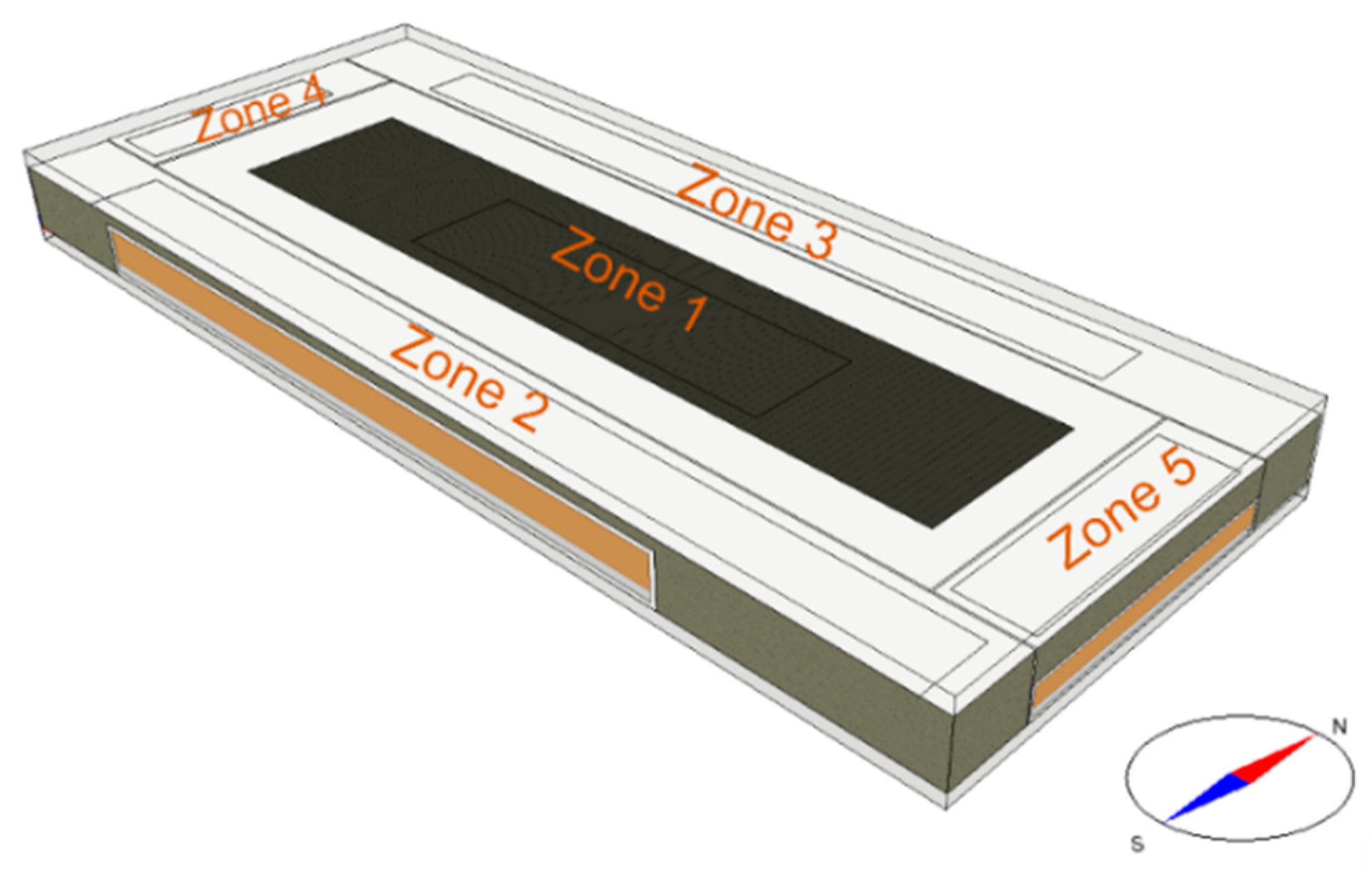
The studied building is a new educational building located in Espoo, Finland. The building is a 4/5-story building with hundreds of rooms. It was designed with an irregular geometry. The heated net floor area of the building is 47,500 m2. The simplification work was conducted in the modeling of the building. The geometry of the building was simplified into a rectangular single-story building with a room height of 4.6 m (shown in Figure 1). The building space was divided into five zones. The zoning considered the different distribution of internal heat gains in the building based on assumptions (see the next section). The eventual geometry was magnified by a zone multiplier of 18.3 to obtain the real net floor area. The overview of general parameters of the building geometry, U-values of the envelope and window properties are shown in Table 1.

2.2.2. Internal Heat Gains

In this study, the simulated five zones were classified into two groups considering different occupancy densities and heat gains from lighting and equipment. Zones 1–3 represent building areas with a lower occupancy density or utilization of lighting and equipment, such as halls, office rooms, gymnasiums, shopping areas, etc. Zones 4 and 5 were considered to have a higher occupancy density or utilization of lighting and equipment, such as classrooms, computer rooms, workshops, etc. The values of occupancy density and annual internal heat gains from lighting and equipment are listed in Table 2. The detailed daily occupancy, lighting and equipment profiles can be found in the study by Xue et al. [46]. In addition, monthly occupancy factors were used to consider the monthly occupancy variation.

2.2.3. Heating and Cooling Distribution System

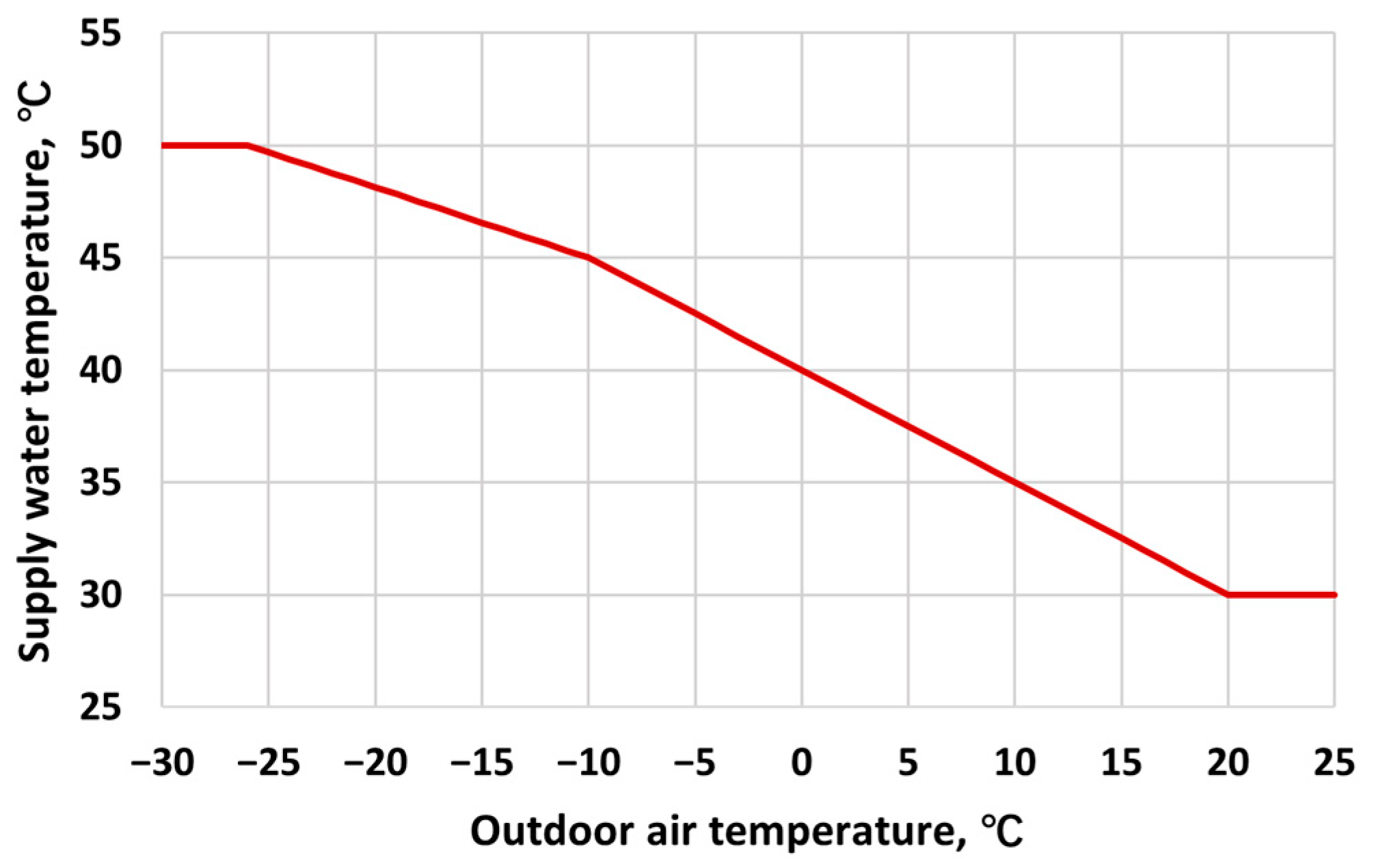
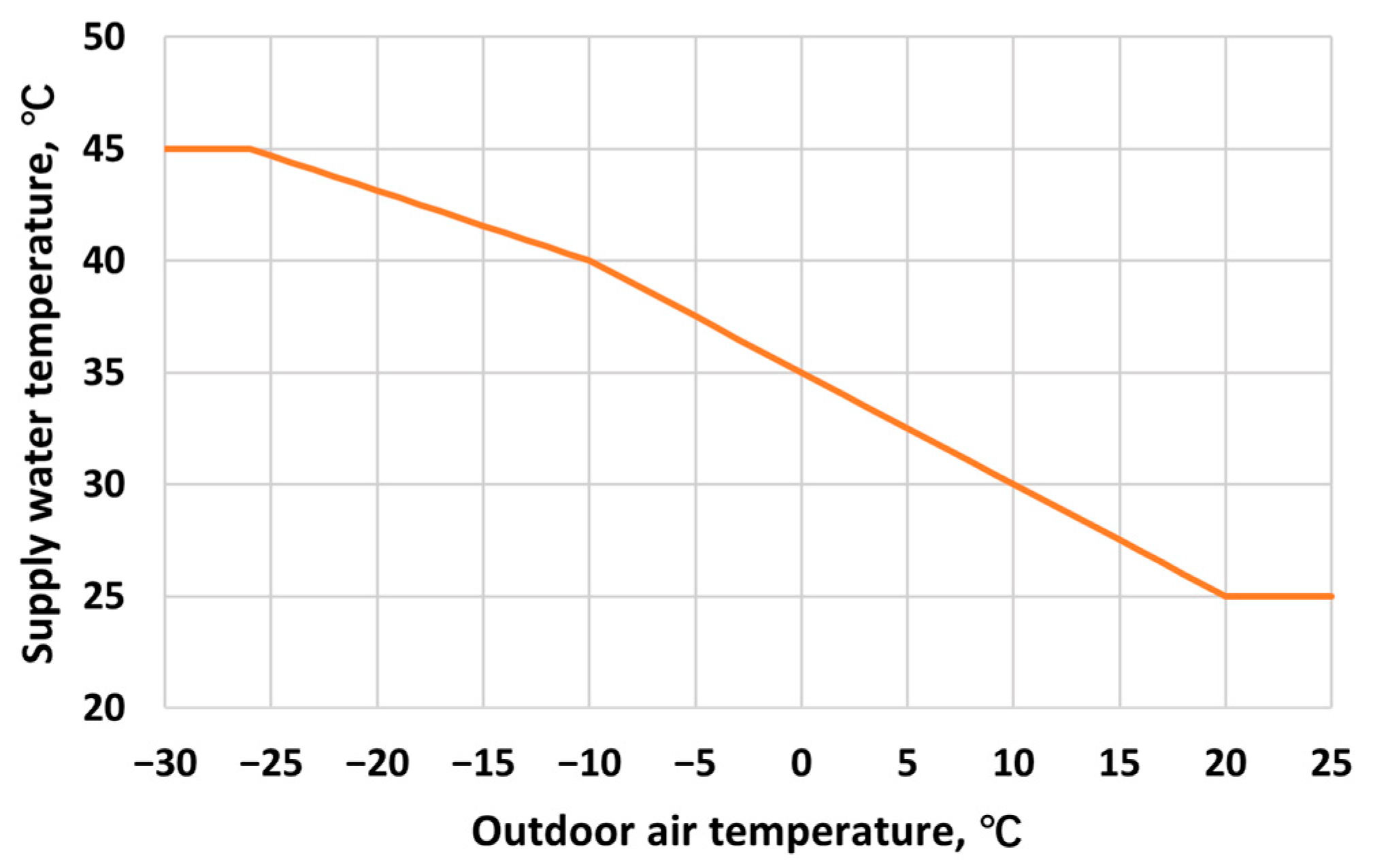
The space heating and cooling energy is distributed by a hydronic four-pipe radiant ceiling panel system. The design powers for space heating and cooling are 19 W/m2 and 9 W/m2, respectively. The indoor setpoints are 21.5 °C for heating and 25 °C for cooling. The dimensioning supply/return water temperatures are 45/30 °C for heating and 15/18 °C for cooling. The supply water temperature for space heating is controlled by the outdoor air temperature according to the control curve shown in Figure 2.

2.2.4. Ventilation System

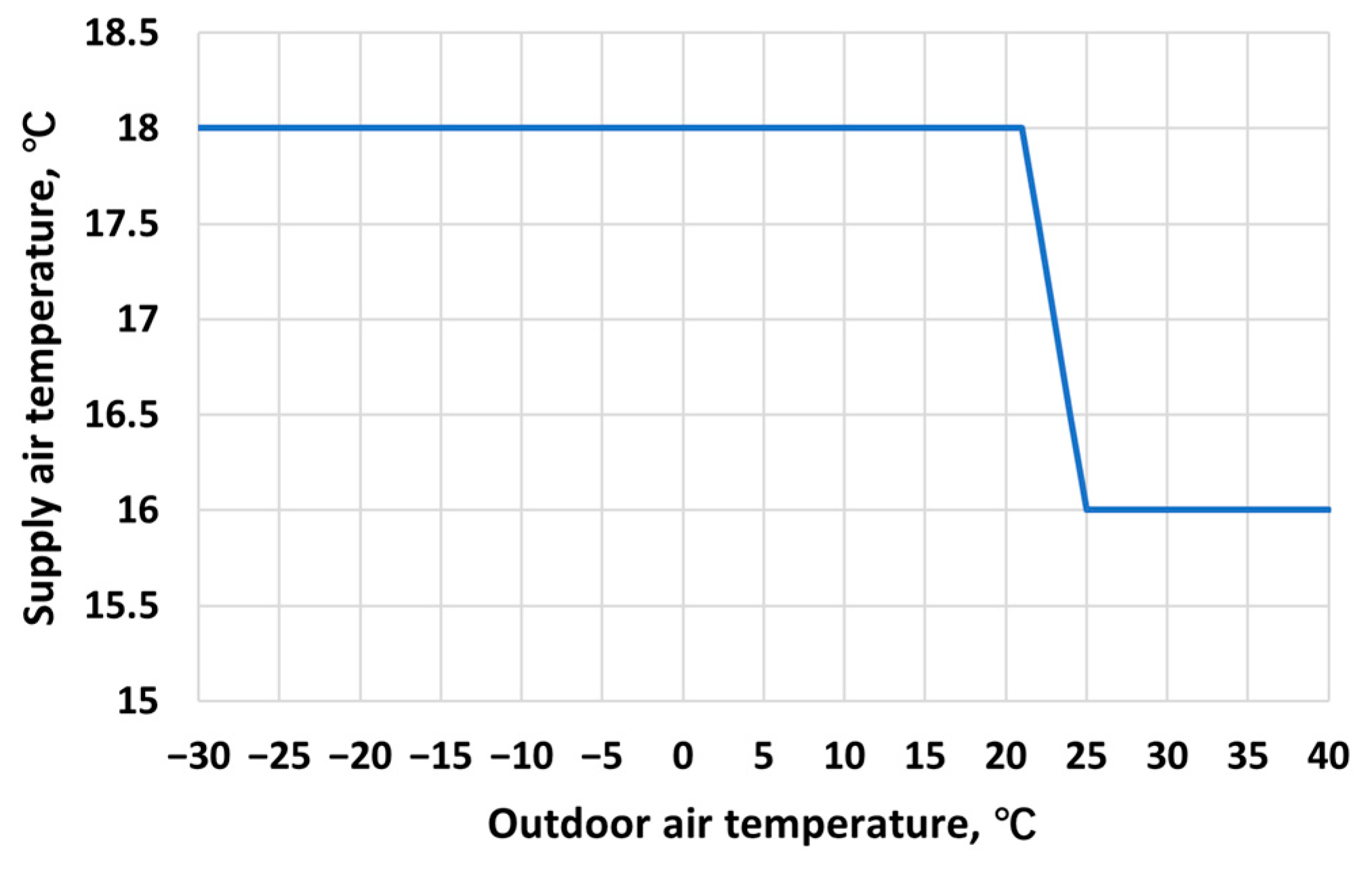
The building has a mechanical balanced ventilation system with heat recovery. The dimensioning supply/return water temperatures for AHU heating are 50/30 °C. The AHU heating supply water temperature is controlled according to the outdoor air temperature by the curve shown in Figure 3. The AHU heat recovery efficiency is 60%. A defrost protection is set in the AHU with a minimum allowed exhaust air temperature of 4 °C. The dimensioning supply/return water temperatures for AHU cooling are 10/16 °C. The ventilation system was modelled with two AHUs in charge of Zone 1 and Zone 2–5, respectively. The detailed air flow rate setting is shown in Table 3. The total supply air flow rate of the building is 123 m3/sm2. The fan operation rate was set at the maximum from 7:00 to 21:00 and 33% at other times during weekdays. The detailed fan operation schedule can be found in the study by Xue et al. [46]. The supply air temperature varies in the range of 16–18 °C as a function of the outdoor air temperature (see Figure 4).

2.2.5. Domestic Hot Water

The domestic hot water (DHW) heating energy demand was set as 4 kWh/m2a. A detailed hourly DHW consumption profile can be found in the study by Xue et al. [46]. The monthly DHW usage factors were used to consider the monthly DHW usage variation.

2.3. Plant Model Description

2.3.1. Hybrid GSHP System Description and Operation Principles

The heating and cooling for the building are provided by the hybrid GSHP system. In the hybrid GSHP system, the main components are the heat pump, the borehole field, the district heating substation, the air-cooled chiller, water storage tanks and pumps. The whole system was built in the IDA ICE plant model. Figure 5 shows a simplified schematic of the hybrid GSHP system. The domestic hot water is heated by the heat exchanger (HX1) in the district heating substation. The supply water for AHU heating and space heating comes from the hot tank coupled to the district heating network via heat exchanger (HX2) and the condenser side of the heat pump. The supply water for AHU cooling and space cooling is from the cold tank connected to the borehole field via heat exchanger (HX3) and the air-cooled chiller.
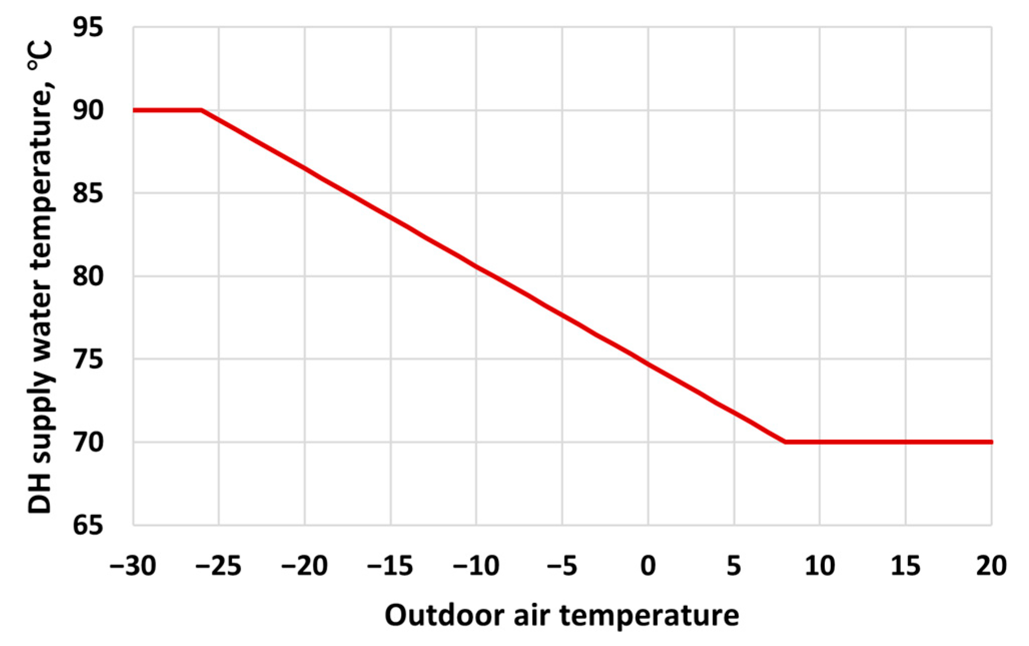
The operation of the back-up heating/cooling is controlled by the water temperature in the hot/cold tank. In heating seasons, the GSHP provides basic heating. The district heating generates auxiliary heat to the hot tank when the water temperature at the top of the hot water tank is lower than the maximum supply water setpoint of the AHU and space heating. The supply hot water setpoint from the GSHP is 2 °C higher than the maximum supply water setpoint for the AHU and space heating. The heat pump will operate at part load condition if the temperature of the hot tank water at 1.6 m reaches the maximum setpoint. The setpoint of the supply temperature from the district heating network varies in the range of 70–90 °C as a function of outdoor temperature (see Figure 6). In cooling seasons, the borehole field produces free cooling water to the cold water tank. The temperature of the free cooling water varies according to the outlet brine temperature from the borehole heat exchangers. If the free cooling cannot cool the water from the bottom layer of the cold tank to the minimum supply water setpoint of the cooling network, the chiller will start operating. The temperature of the supply cold water from the chiller is 2 °C lower than the minimum supply water setpoint for the AHU and space cooling.

2.3.2. Heat Pump Model

The heat pump model used in this study is a brine-to-brine heat pump model from the standard IDA ICE component library. The model comprises a heat exchanger model for the condenser and the evaporator and a performance descriptive correlation model for the compressor [47]. The heat exchanger model is developed based on the NTU method. The heat pump model allows performance at arbitrary condenser and evaporator temperatures within the designed temperature limits. In addition, the heat pump model can simulate part load conditions. The details of IDA ICE heat pump model were described in the study of Niemelä et al. [48].
In this study, the real GSHP system consists of 9 heat pump modules with each nominal heating capacity of 87.8 kW and COP of 3.94 at rating conditions of 35/0 °C [49]. The 9 heat pump modules were simply modelled as one heat pump in IDA ICE 4.8 with the nominal COP at rating conditions and an equivalent total heating capacity of 790 kW.

2.3.3. Borehole Field Model

The borehole field was modelled by using the IDA ICE ground heat exchanger (IDA GHX) model based on the finite difference method. The IDA GHX model consists of a 3-D field by superposition of cylindrical 2-D temperature fields around each borehole and a 1-D vertical field for undisturbed ground temperatures including geothermal temperature gradient. A detailed description of the borehole field model and the corresponding validation result were presented in the study by Xue et al. [42].
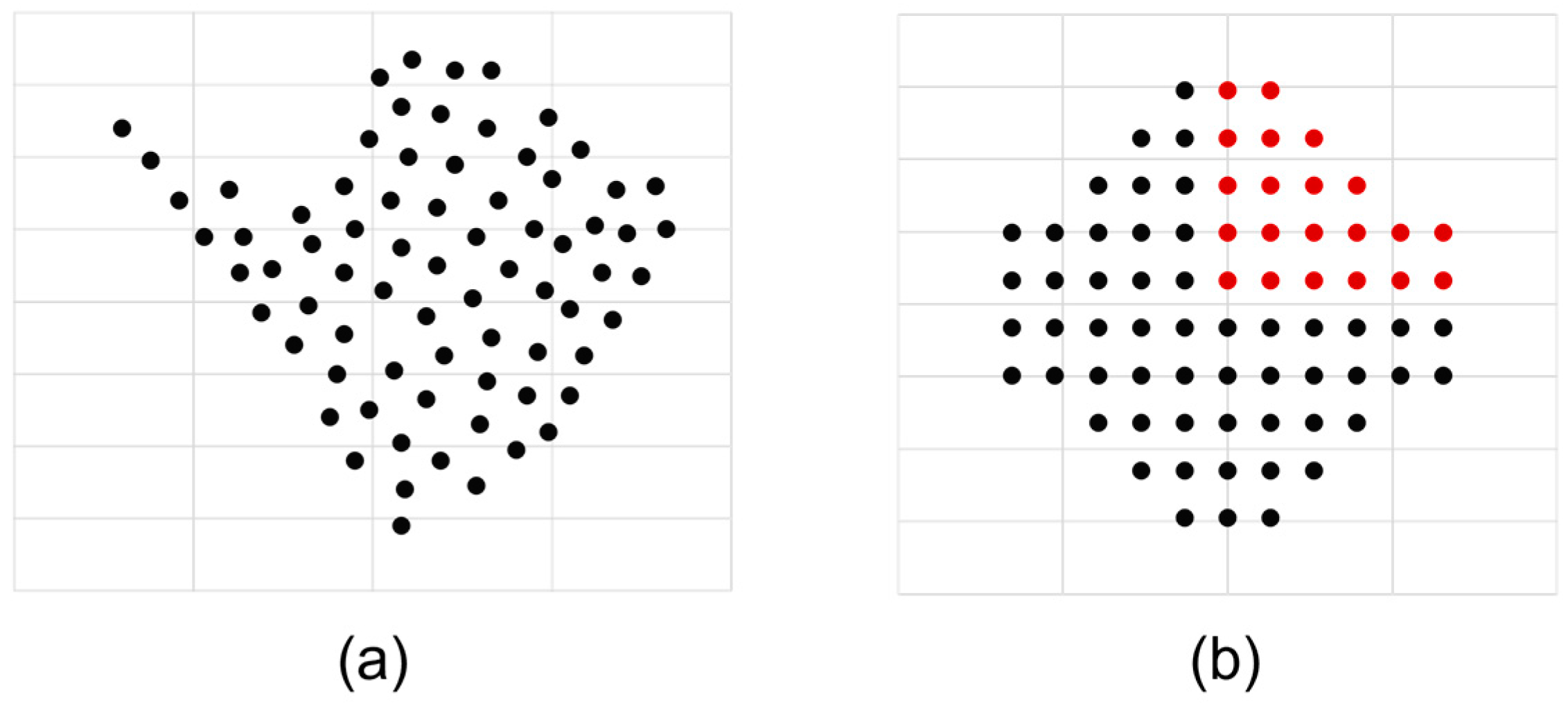
The overview of the borehole field parameters is listed in Table 4. The boreholes are filled with groundwater. The groundwater was regarded as a solid material in the simulation. The natural convection of the groundwater was considered by using an effective thermal conductivity of water [42]. The surrounding bedrock is homogenous granite with negligible fracturing. The groundwater level and granite structure are 8.2–9 m below the ground surface. The borehole heat exchangers are single U-pipe heat exchangers using 28% ethanol-water as the working fluid. All heat exchangers are connected in parallel. The original borehole field was designed in an irregular geometry as shown in Figure 7a by a consultancy company. According to the validation work in the previous study [42], the borehole field layout can be simplified into a double-symmetry geometry as shown in Figure 7b without scarifying the accuracy of the simulation result. The eventual simulation result of the borehole field was created by duplicating the results of the simulated 21 boreholes marked as red dots in Figure 7b.

2.3.4. Auxiliary Heating and Cooling and Storage Tank Models

The auxiliary heating and cooling are provided by the district heating and the air-cooled chiller. The district heating substation efficiency is 97%. The energy efficiency ratio (EER) of the air-cooled chiller is 3.04. The dimensioning power of the back-up district heating and air-cooled chiller is introduced in the case design in Section 2.7.
The hot and cold water storage tanks were both modelled by using the non-ideal stratified water tank model in IDA ICE. The water tank model allows users to divide the height of the storage tank into different layers, and thus, it can simulate the heat transfer between layers due to the mixing process. The non-ideal water storage tank model was validated by Alimohammadisagvand et al. [50]. More details of the tank model can be found in their study. In this study, the volume of the hot water tank was set as 5 m3 with a height of 2.2 m, and the volume of the cold water tank was set as 3 m3 with a height of 2.0 m. Each tank was divided into 8 layers vertically.

2.4. Life Cycle Cost

The life cycle cost (LCC) analysis was conducted for investigating the economic impact of long-term performance improvement methods. The life cycle period in the LCC analysis was assumed to be 25 years. The LCC of the hybrid GSHP system was calculated by Equation (1):
L C C = I 0 ,   t o t + M t o t + R t o t + E t o t R e s t o t ,
where LCC is the life cycle cost over a 25-year time period, EUR; ΣI0,tot is the overall investment cost of the system, EUR; ΣMtot is the total maintenance cost of the system, EUR; ΣRtot is the overall renewal cost, EUR; ΣEtot is the total energy cost of the case building, EUR; ΣRestot is the total residual value of the system, EUR.
In this study, the LCC calculation only considered costs concerning the GSHP, boreholes, back-up district heating substation for space and ventilation heating, air-cooled chiller and AHU cooling coils. The costs of other equipment in the heating and cooling system were not calculated since they remained the same for all studied cases. The overview of specific investment, maintenance, renewal costs and residual values inclusive of the Finnish VAT of 24% are shown in Table 5. The investment costs were based on cost estimations from the designers and manufacturers. In the investment cost calculation of AHU’s cooling coils, the number of AHUs in the actual building was considered even if the building model was simulated with two AHUs. The maintenance, renewal cost and residual values were based on the cost data from the study by Niemelä et al. [51] and updated to the relevant market prices in 2022. It was assumed that renewal of the compressors in the GSHP and chiller will occur in the 15th year.
The total maintenance cost of the hybrid GSHP system was calculated by Equation (2):
M t o t = 1 1 + r n r · M a ,
where r is the real interest rate; n is the number of years of the system lifetime, a; and Ma is the annual maintenance cost of the system, EUR/a.
The total renewal cost of the hybrid GSHP system was calculated by Equation (3):
R t o t = 1 1 + r k i · R M ,
where r is the real interest rate; ki is the number of years starting when the renewal is implemented; and RM is the renewal cost of the renovation measure, EUR.
The total energy cost of the building was calculated by Equation (4):
E t o t = i = 1 n E i 1 + r e i ,
where re is the escalated real interest rate, including an estimated energy price escalation rate in the future; n is the number of years of the system lifetime, a; and Ei is the annual energy cost of the system in the ith year, EUR.
Table 6 gives the distribution and power fees of electricity and district heating. The distribution fee of electricity included the basic fee, power fee and distribution fee in the daytime in winter and at other times. The basic power fee of district heating was determined by the maximum power output of the district heating connection in the studied building.
The sensitivity analyses were conducted with two scenarios considering the effects of the Russian–Ukraine war [52] on the Finnish energy market. Scenario 1 was the price scenario before the war, which was represented by the initial year 2019 of the simulation. Scenario 2 was the price scenario after the war started, which was represented by the year 2022. The differences in the real interest rate and energy escalating rate were also considered in these two scenarios. The energy prices used for the two scenarios are given in Table 7. The presented energy prices considered all taxes including the Finnish VAT of 24%. The monthly electricity prices were taken from Nord Pool [53]. The monthly district heating prices were from a local district heating provider. The real interest rate and the energy escalation rate in Scenario 1 were set as 4.4% and 2%, based on the previous LCC analysis of a Finnish educational building [54]. A higher real interest rate and a lower energy escalation rate were assumed in Scenario 2, which were 5% and 1%, respectively.

2.5. CO2 Emissions

The environmental impact was assessed according to the CO2 emissions due to the energy use of the building. The CO2 emissions of consumed electricity and district heating during the lifetime of the hybrid GSHP system were calculated by using the corresponding CO2 emissions factors. The CO2 emissions factor for the electricity consumption was chosen as 63 kgCO2/MWh, which was the average value in 2021 defined by Finnish Energy [55]. The CO2 emissions factor for the district heating consumption was chosen as 118 kgCO2/MWh based on the average value in 2021 from a local district heating provider.

2.6. Model Validation

The validation of the borehole field model was already conducted in the previous study [42] from March 2018 to February 2021. In this study, the validation of the building and the hybrid GSHP models were performed with 1-year simulated and measured results from July 2019 to June 2020. The measured data were obtained from the measurement and reconstructed by Todorov et al. [56]. The building model was validated through the comparison of the monthly energy demand of heating, cooling and DHW with the measured values. The hybrid GSHP system model was validated via the annual ground thermal imbalance ratio (IR), average heat pump COP and GSHP heating energy ratio (HR) in the heating season (September–May) and borehole free cooling energy ratio (CR) in the cooling season (June–August).
The ground thermal imbalance ratio (IR) for assessing the annual thermal balance of the ground was defined by Equation (5):
I R = Q e x t Q i n j Q m a x × 100 % ,
where Qext and Qinj are annual accumulated heat extraction and heat injection, respectively, kWh. Qmax is the maximum value between Qext and Qinj.
The GSHP heating energy ratio (HR) was defined as the ratio of the heating energy provided by the GSHP to the total space and AHU heating energy demand in the heating season. It was calculated by Equation (6):
H R = Q G S H P Q h e a t i n g ,   t o t × 100 % ,
where QGSHP is the total condenser heat of the GSHP in the heating season, kWh; and Qheating,tot is the total heating energy demand required by space and AHU heating in the heating season, kWh.
The borehole free cooling energy ratio (CR) was defined as the ratio of the cooling energy covered by the borehole field to the total cooling energy demand in the cooling season, which was calculated by Equation (7):
C R = Q B H X Q c o o l i n g , t o t × 100 % ,
where QBHX is the injected heat to the ground in the cooling season, kWh; and Qcooling,tot is the total cooling energy demand in the cooling season, kWh.

2.7. Case Design

The input borehole load data used in the previous research presented a higher amount of extracted heat from the ground, which indicates a potential risk of long-term brine temperature drop and GSHP performance deterioration [42]. Therefore, in this study, seven simulation cases were designed and compared for investigating effects of different improving methods on the hybrid GSHP system. The design parameters of these cases are listed in Table 8. Case 1 is the reference case based on the actual designs of the building and hybrid GSHP system. Cases 2–4 are designed for comparing the primary performance improving methods used on the building side. In Case 2, the AHU cooling water supply/return temperatures were increased to 15/18 °C in order to use more free cooling energy in cooling seasons. However, it will require larger cooling coils and consequently increase the coil investment cost. Case 3 is designed based on Case 2, while the cooling setpoint is reduced to 22.5 °C to further increase the ground cooling load. Case 4 is an improved case of Case 3, in which the heating setpoint is reduced to 21 °C in order to reduce the ground heating load. Cases 5–7 are designed based on Case 4 for comparing additional methods applied on the hybrid GSHP system. In Case 5, the nominal GSHP heating power is reduced by 30%, which indicates less extracted heat from the ground and more usage of back-up heating. In Cases 6 and 7, the borehole number and the borehole depth are increased by 30%, respectively, which can increase the total heat exchange per borehole.
The nominal power of the back-up district heating for space and AHU heating was determined based on the dimensioning heating power for space and AHU heating and the nominal heating power of the heat pump. The dimensioning heating demand of space and AHU heating was calculated without internal heat gains under the dimensioning outdoor temperature (−26 °C) of southern Finland. Therefore, the dimensioning heating power of the back-up district heating substation was determined by subtracting the nominal power of GSHP from the dimensioning total heating power. The dimensioning of the district heating power for DHW was not considered in this study since the DHW was heated separately by a heat exchanger, and the DHW heating demand remained the same for each case.
As the borehole free cooling power is affected by both the ground and borehole characteristics, the input nominal power of the air-cooled chiller was not limited for simulations in this study. The dimensioning cooling power of the air-cooled chiller for LCC analysis was determined according to the maximum cooling power demand in the long-term simulation.

2.8. Weather Data and Simulation Period

The simulations of the studied cases were conducted for 25 years from July 2019 to June 2044. The input weather data were based on the measured data from weather stations of the Finnish Meteorological Institute nearby the studied building. The input 25-year weather data were generated by using the measured weather data from 2019 to 2021 as a period and repeating it for 25 years. Within this period, the outdoor temperature ranges from −23.9 °C to 32.4 °C and the annual average outdoor temperature ranges from 6.2 °C to 8.1 °C. The time resolution of the weather data is 1 h.

3. Results

3.1. Dimensioning Heating and Cooling Power

The dimensioning back-up heating and cooling powers are shown in Table 9. The dimensioning heating power demand of space and AHU heating was rounded up to the next nearest 100 kW at the dimensioning outdoor temperature of −26 °C. The dimensioning heating power of the back-up district heating was calculated by subtracting the nominal power of GSHP (see Table 8) from the dimensioning heating power. The dimension power of the back-up chiller was determined based on the maximum chiller power in the simulated 25 years, which was rounded up to the next nearest 10 kW.

3.2. Building and Hybrid GSHP System Validation

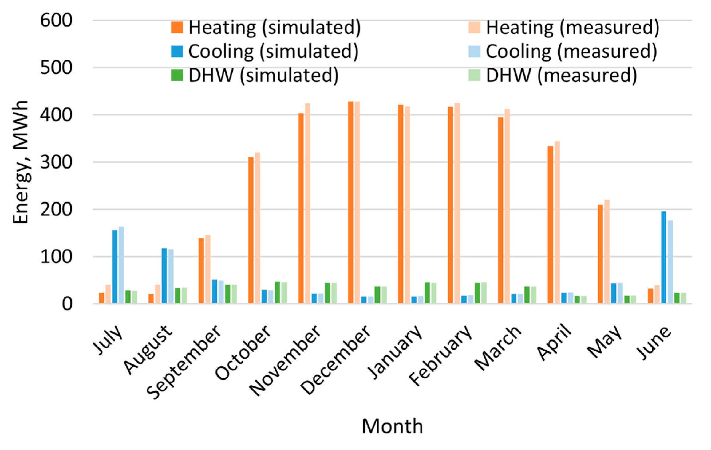
The annual heating, cooling and DHW energy demand during the validation year were compared between the simulation result of the reference case and the measured data. The measured results were calculated based on the reconstructed measured data by Todorov et al. [56]. The measured annual heating energy demand for space and AHU heating was 3261 MWh, while the simulated annual heating energy demand was 3135 MWh, which presents a discrepancy of 4%. The annual cooling energy demand for space and AHU cooling was 696 MWh and 708 MWh from the measured and simulated results, respectively, with a difference of 2%. The measured annual DHW energy demand was 414 MWh with an insignificant deviation from the simulated DHW demand. Figure 8 shows the comparison of monthly heating, cooling and DHW energy demand from the measurement and simulation. A good agreement can be observed between the simulated and measured results. The deviations between the simulated and measured values are within 5% for the monthly heating energy demand in the heating season and the monthly cooling energy demand in the cooling season. The deviation in the monthly DHW energy demand is within 3%.
The hybrid GSHP system was validated based on the annual ground thermal imbalance ratio (see Equation (5)), average heat pump COP and GSHP heating energy ratio in the heating season (see Equation (6)) and borehole free cooling energy ratio in the cooling season (see Equation (7)). The validation results of the hybrid GSHP system are given in Table 10. It can be seen that the results from the simulation and the measurement match well. The deviations in ground thermal imbalance ratio, average hourly heat pump COP, GSHP heating energy ratio and borehole free cooling energy ratio are less than 5%.
The validation of the simplified-geometry borehole field model was conducted in the previous study [42]. The result showed the accuracy of predicted inlet and outlet brine temperatures was within 1 °C against the measurement during the validation period.

3.3. Hybrid GSHP Performance Analysis

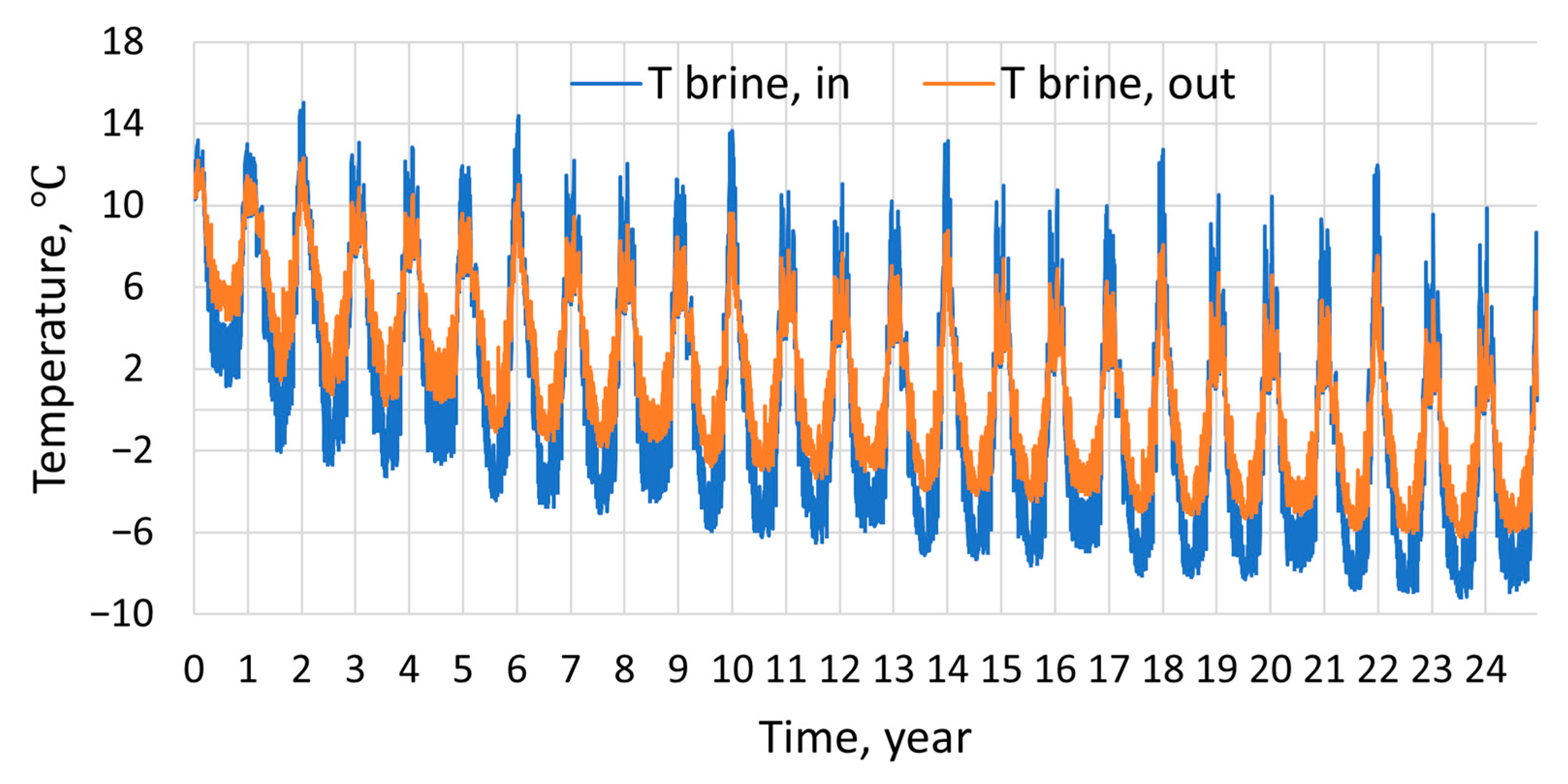
The inlet and outlet brine temperatures of the borehole field were simulated over 25 years. Figure 9 shows the curves of inlet and outlet brine temperatures of the borehole field with a time resolution of 1 h for Case 1 (reference case). As the figure shows, inlet and outlet brine temperatures of the borehole field drop severely after 25 years.
The minimum and average brine temperatures in the heating season (September–May) and the maximum and average brine temperatures in the cooling season (June–August) were analyzed to compare different cases. Table 11 and Table 12 show the inlet and outlet brine temperatures in the first and last years, respectively. In Case 1, the maximum outlet brine temperature of 12.2 °C in the first year decreases to 5.6 °C in the last year; and the minimum outlet brine temperature during the heating season drops even to −6.0 °C in the last year, which is far below the design minimum outlet brine temperature of 0 °C for Nordic countries [57]. In Case 2, increasing the AHU cooling water temperature level has an insignificant effect on the brine temperatures in the heating season but reduces the brine temperatures in the cooling season in the last year. The reason for this could be that even if the free cooling usage time is longer in Case 2, the accumulated injected heat still decreases as the condensation in AHUs is reduced due to a higher AHU cooling water temperature level. In Case 3, when the cooling setpoint is lower, the brine temperatures increase not only in the cooling season but also in the heating season of the last year. The higher brine temperatures in the heating season could be due to the seasonal storage effect. In Case 4, reducing the heating setpoint can further increase the brine temperatures in the heating season but has less effect on the brine temperatures in the cooling season. However, in Case 4, the minimum outlet brine temperature in the last heating season can only rise to −3.1 °C, which is still lower than the required minimum outlet brine temperature of 0 °C.
As shown in Cases 5–7, the minimum brine temperatures in the last heating season can be further increased by reducing the GSHP heating capacity or by increasing the total borehole length. It seems that the minimum outlet brine temperature in the last heating season increases more significantly by increasing the total borehole length (Cases 6 and 7) than reducing the GSHP heating capacity (Case 5). In addition, the minimum outlet brine temperature in the last heating season is higher in Case 7 with a longer borehole depth than in Case 6 with a higher number of boreholes. This could be due to a higher soil temperature in deepened boreholes (Case 7) or an intensified thermal interaction induced by extra boreholes (Case 6). In Case 7, the minimum outlet brine temperature in the last heating season is 0.1 °C. Even though in Case 7 the minimum inlet brine temperature is −2.7 °C, the average inlet brine temperature in the last heating season can still reach 0.2 °C.
Table 13 gives the ground thermal imbalance ratios (see Equation (5)) in different cases. It can be seen that the reference Case 1 shows an extremely high thermal imbalance ratio of 90% in the initial year, which means the annual heat in the ground can only recover by 10%. Based on Case 1, raising the AHU cooling water temperature level can mitigate the thermal imbalance in the first year to 86% in Case 2. This ratio can be further reduced to 78% in Case 3 by using a lower indoor cooling setpoint and to 77% in Case 4 by further using a higher indoor heating setpoint. However, the ground thermal imbalance in the first year does not change significantly in Cases 5–7 when the change occurred in the GSHP heating capacity or the total borehole length. This might be due to the accumulated heat extraction being reduced insignificantly in the initial year.
An obvious decrease in the ground thermal imbalance ratio can be noticed after 25 years in all cases since the decreasing brine temperature results in less heat extracted in the heating season and more heat injected in the cooling season. In Case 1, the thermal imbalance ratio is reduced to 76% in the last year. However, in Case 2, the thermal imbalance ratio in the last year is 79%, which is higher than the reference case. The reason for this may be that the higher AHU cooling water temperature level reduces the AHU cooling energy demand due to less condensation on the AHU cooling coil. Therefore, the accumulated injected heat to the ground in Case 2 is less than that in Case 1. The thermal imbalance ratio in the last year decreases to 66% in Case 3 by lowering the cooling setpoint and to 64% in Case 4 by further lowering the heating setpoint. In Case 5, the reduction in accumulated heat extraction becomes significant due to the reduced GSHP heating capacity, mitigating the thermal imbalance to 60%. In Cases 6 and 7, when the total borehole length is increased, the ground thermal imbalance ratio is 1 percentage point higher than that in Case 4. The reason for this could be that a longer total borehole length results in a greater increase in heat extraction compared to heat injection, attributed to the lower borehole thermal resistance in the heating mode.
The hybrid GSHP system performance was analyzed by the average heat pump COP and the GSHP heating energy ratio (see Equation (6)) in the heating season and the borehole free cooling energy ratio in the cooling season (see Equation (7)). Table 14 and Table 15 show the hybrid GSHP performance of different cases in the first and last years, respectively. It can be seen that the average COP of GSHP in the heating season decreases after 25 years. In Case 1, the average COP in the last heating season is 3.42, which is 9% lower than that in the first heating season. By increasing the AHU cooling water temperature level and lowering the cooling and heating setpoint, the average COP in the last heating season is increased by 3% in Case 4 compared to Case 1. In Cases 5–7, the average COP in the last heating season can be further improved by reducing the GSHP heating capacity or increasing the borehole number or borehole depth. The highest COP of 3.63 in the last heating season is achieved in Case 5 with a lower GSHP heating capacity.
The GSHP heating energy ratio also decreases after 25 years. This is because the GSHP heating capacity deteriorates over time as a result of the decreasing evaporation temperature. In Case 1, the GSHP can cover 95% of the total heating energy demand in the first year, while in the last year, it can only provide 90% of the total heating energy demand. In Cases 2 and 3, the GSHP heating energy ratio is not affected by changing the AHU cooling water temperature level or the cooling setpoint. In Case 4, the lower heating setpoint helps rise the GSHP heating ratio to 92% in the last year. In Cases 6 and 7, by increasing the total borehole length, the GSHP heating ratio in the last year can be further increased to 93%. However, the ratio in the last year decreases to 83% in Case 5 due to a reduced nominal GSHP heating power.
In contrast to the GSHP heating energy ratio, the borehole free cooling energy ratio increases significantly after 25 years in all cases. In Case 1, the borehole field can cover half of the total cooling energy demand in the first year, while in the last year, the borehole free cooling energy ratio increases to 97%. In Case 2, when the AHU cooling water temperature level increases, the borehole field can satisfy 75% of the total cooling energy in the first year and even all the cooling energy in the last year. In Cases 3 and 4, as the cooling setpoint is lowered, the total cooling demand increases significantly. Therefore, compared to Case 2, borehole free cooling energy ratios in Cases 3 and 4 are slightly lower, both of which are 72% in the first year and 99% in the last year. However, the borehole free cooling energy ratio in the last year varies insignificantly with a reduced GSHP heating capacity (Case 5) or an increased total borehole length (Cases 6 and 7).

3.4. Energy Consumption Analysis

The total energy consumption was calculated and compared for studied cases. The breakdown of total electricity and district heating consumptions in 25 years is shown in Table 16. The relative differences between reference Case 1 and improved Cases 2–7 are also given in the table. In Case 1, the total electricity and district heating consumptions are 1053 kWh/m2 and 415 kWh/m2, respectively. The GSHP accounts for 42% of the total electricity consumption, while the air-cooled chiller only uses 1% of the total electricity. The back-up district heating in Case 1 is responsible for 75% of the total district heating consumption. In Case 2, increasing the AHU cooling water temperature level leads to a 70% reduction in the electricity consumption of the air-cooled chiller. However, since the air-cooled chiller consumes a marginal amount of electricity, the total electricity consumption is only reduced by 1%. In Case 3, by additionally using a lower cooling setpoint, the total electricity consumption increases by 2%, which is mainly ascribed to higher electricity consumption by the GSHP due to a higher heating energy demand. In addition, the district heating consumption in Case 3 also increases by 2%. The reason for the increasing energy consumption is that the lower cooling setpoint results in less heat stored in the envelope as some zones have cooling demand in the occupied time of heating seasons, and subsequently, more heating is needed for the unoccupied time. In Case 4, the electricity used for the GSHP and the back-up district heating presents a reduction due to a lower heating setpoint. Thus, the total electricity and district heating consumption decreases by 1% and 6%, respectively, compared to the reference case. By further reducing the GSHP heating power, a significant reduction in GSHP electricity consumption is observed in Case 5. The total electricity consumption consequently drops by 6%. In return, the total district heating consumption is 36% higher than the reference case. In contrast, by installing more boreholes or drilling deeper boreholes, the GSHP can generate more heating energy. Thus, the total district heating consumption is reduced by 12% in Case 6 and by 14% in Case 7.

3.5. Life Cycle Cost Analysis

The system LCCs in scenarios 1 and 2 are shown in Table 17 and Table 18, respectively. Compared to scenario 1, the LCC values in scenario 2 are significantly higher due to more expensive energy costs. However, in both scenarios, the improved cases (Cases 2–7) show insignificant differences in LCC compared to reference case 1. The minimum LCC in both scenarios is only 2% lower than that of the reference case. In scenario 1, the minimum LCC is realized in Case 4 when the higher AHU cooling temperature level and lower heating and cooling setpoints were both used. In scenario 2, the case with the lowest LCC is Case 5, in which the GSHP heating capacity is reduced by 30% compared to Case 4.

3.6. CO2 Emissions Analysis

The total CO2 emissions for studied cases are shown in Table 19. The total CO2 emissions for 25 years in the reference case was 5479 tons. It can be seen that increasing the AHU cooling water temperature level can reduce the total CO2 emissions in Case 2. This is mainly because the CO2 emissions from electricity are reduced by using more free cooling energy in cooling seasons. However, in Case 3, reducing the indoor cooling setpoint increases both CO2 emissions from electricity and district heating consumptions due to the higher heating energy demand. In contrast, in Case 4, lowering the indoor heating setpoint can reduce the total CO2 emissions as a result of the reduced heating energy demand. Compared to the reference case, the total CO2 emissions can be reduced by 3% in Case 4. The total CO2 emissions vary differently among Cases 5–7. Case 5 shows reducing the GSHP power can increase the CO2 emissions, which is mainly attributed to more CO2 emissions from district heating. The total CO2 emissions in Case 5 are 12% higher than that in the reference case. By contrast, Cases 6 and 7 reveal reductions in total CO2 emissions. The total CO2 emissions drop by 5% in Case 6 with more boreholes and by 6% in Case 7 with the longer borehole depth. The lower total CO2 emissions in Case 7 are mainly attributed to a more significant CO2 reduction in district heating.

4. Discussion

According to the study, the outlet brine temperature in the reference case dropped far below the temperature limit of 0 °C for Nordic countries [57]. It indicates the simulated borehole field was undersized for the GSHP in the reference case. The undersized dimensioning borehole field could be attributed to the misestimation of the heating power demand of the building, ground thermal properties or the groundwater level in the design phase [24]. The undersized borehole field has been noticed by the building owner; some measures relating to improving the ground thermal balance have already been implemented in the actual building.
This study compared several cases using different performance improvement methods. In most studied cases, the brine temperature dropped below 0 °C, which means the groundwater in the borehole could freeze. In this study, the phase change process was not considered for the groundwater. This may lead to an underestimation of the brine temperature and the heat pump COP since freezing can bring advantages to the borehole heat transfer in practice. The freezing process will release significant latent heat. In addition, the already existing ice will enhance the borehole heat transfer as its thermal conductivity is nearly three times higher than that of water. And even though the convective flow in the water increases the heat transfer rate compared to the stagnant water, the ice still presents a generally higher heat transfer rate than the water in boreholes. The borehole thermal resistance of the entirely frozen borehole is around 20% lower than that of the borehole at 6 °C [58].
However, the freezing process might cause damage to the pipes due to the volume expansion of water. The damage may happen only when the water is trapped between two ice blocks [24]. If the water is stuck between two ice blocks and the borehole is watertight, the overpressure will happen while the water is freezing. The pressure will deform the U-pipe, reduce the brine mass flow rate, and thus degrade the GSHP performance. If the surrounding bedrock has fissures, they can drain the pressure water and lessen pipe damage. Nevertheless, additional measures are still needed to prevent the overpressure problem.
The easiest way is to avoid freezing in the borehole. Normally, in practice, the GSHP system is controlled to be shut down automatically when the outlet brine temperature is below the temperature limit. In the study, the optimal case can maintain the outlet brine temperature above 0 °C for 25 years, whereas the inlet brine temperature still dropped below 0 °C due to the temperature drop in the evaporator. This indicates the water can be still partly frozen in the borehole. To fully eliminate freezing in boreholes, the minimum temperature limit for the GSHP in heating mode could be increased to 2–3 °C. Apart from the GSHP control, additional measures on the borehole side could be implemented. These measures can be changing the filling of boreholes, blowing air into the borehole, adding air-filled soft tubes in the boreholes, using perforated casing, etc. [24].
The study implemented lower indoor heating and cooling setpoints to mitigate the brine temperature drop and improve the heat pump COP. The cooling and heating setpoints were reduced from 25 °C to 22.5 °C and from 21.5 °C to 21 °C, respectively, in some studied cases. The variation of design heating and cooling setpoints could affect indoor thermal comfort. However, as the indoor temperature setpoints were in accord with the temperature limits given by the Finnish classification of indoor climate [59], the change from the thermal environment was supposed to be in the comfortable range.
The study showed that increasing the total borehole length is more beneficial to mitigate the brine temperature drop compared to reducing the nominal GSHP heating power by the same proportion. The total borehole length was increased by adding extra boreholes or deepening the boreholes in this study. In the latter case, it was assumed that deeper boreholes are drilled in the initial drilling phase instead of obtained by deepening existing boreholes since some boreholes are under the building. In principle, the boreholes beneath the building are impossible to be extended. In addition, even though boreholes can be deepened, they might bring about uncertainty in the drilling cost. In this study, the additional drilling cost was assumed to be 20% of the original cost for the depth under 310 m based on the reference by Gehlin et al. [57]. However, the actual drilling cost could vary according to the hardness of the rock. A harder rock requires changing the drill bit and increasing the energy used for drilling, which needs more additional cost. Therefore, compared to deeper boreholes, drilling more boreholes would be more viable in practice if there was enough space.
This study only investigated the ratio of 30% for reducing the GSHP heating power and increasing the total borehole length. This ratio can be further increased to obtain a more stable performance of the hybrid GSHP system. Further cost optimization work can even be performed to find the optimal design of the heat pump capacity and the total borehole length.
According to the analysis of CO2 emissions, the case with a longer borehole depth revealed the minimum CO2 emissions, while the case with reduced GSHP power showed a significant increase in CO2 emissions. However, the result was unsurprising since the CO2 emissions factor used for district heating (118 kgCO2/MWh) was much higher than that for electricity (63 kgCO2/MWh). The variation of CO2 emissions factors can substantially impact the total CO2 emissions. Currently, the decarbonization of electricity and district heating generation is ongoing in Finland to realize the carbon-neutral target by 2035 [60]. A more detailed analysis of the hybrid GSHP system could be conducted from the aspect of different decarbonization scenarios in future work.
The weather data used for the 25-year simulation was developed based on the measured data from 2019 to 2021. As global warming occurs gradually, the studied building may have a lowering heating demand and an increasing cooling demand in the future [61]. The variation of the heating and cooling demand may impact the result of long-term simulation for the hybrid GSHP system. Therefore, a deeper investigation is needed in the future for the design of hybrid GSHP systems in global warming scenarios.

5. Conclusions

A hybrid GSHP system combined with district heating and an air-cooled chiller was modelled and simulated in IDA ICE 4.8 to investigate the effective methods for improving the system long-term performance. Different methods, such as rising the AHU cooling water temperature level, lowering the indoor cooling and heating setpoints, reducing the nominal GSHP heating capacity and increasing the borehole number or borehole depth, were compared based on their effects on the system energy performance, life cycle cost and CO2 emissions.
The validation result showed the developed building and hybrid GSHP system models in IDA ICE 4.8 were eligible for simulations. The building model with simplified geometry and zoning can predict annual and monthly energy demands accurately. In addition, the hybrid GSHP system model can estimate the system performance with sufficient accuracy in the annual ground thermal imbalance ratio, average heat pump COP and GSHP heating energy ratio in the heating season and borehole free cooling energy ratio in the cooling season.
In the reference case, the brine temperature dropped significantly over time, resulting in a heating performance deterioration of the hybrid GSHP system. After the 25-year operation, the minimum outlet brine temperature in the heating season dropped from 4.4 °C to −6 °C, indicating a freezing risk of the borehole field. The average heat pump COP and the GSHP heating energy ratio in the heating season dropped by 9% and 5 percentage points, respectively, after 25 years. However, the decreasing brine temperature enhanced the borehole free cooling, which can cover 97% of the cooling energy demand in the last cooling season.
The freezing risk can be lowered by primary improving methods on the building side. In the case with a higher AHU cooling water temperature level and lower cooling and heating setpoints, the annual ground thermal imbalance ratio in the last year was reduced by 12 percentage points, and the minimum outlet brine temperature in the last heating season was increased by around 3 °C compared to the reference case. In addition, in the improved case, the average heat pump COP in the last heating season was increased by 3%, and the GSHP heating energy ratio in the last heating season was improved by 2 percentage points.
However, apart from adjusting the AHU cooling water temperature level and indoor heating and cooling setpoints, extra improving methods, such as reducing the GSHP power or increasing the total borehole length, were still needed for guaranteeing long-term operation. The result showed that increasing the total borehole length was more effective in maintaining the brine temperature level compared to reducing the GSHP capacity. The minimum outlet brine temperature can be increased to above 0 °C in the last heating season when the borehole depth was further increased by 30%.
The improving methods had an insignificant effect on the LCC of the hybrid GSHP system. The relative LCC differences between the improved and referenced cases were all within 2% in the two analyzed scenarios.
The CO2 emissions of the hybrid GSHP system were affected variously by different improving methods. By adjusting the AHU cooling water temperature level and indoor heating and cooling setpoints, the total CO2 emissions for 25 years were reduced by 3%. By further reducing the GSHP heating power or extending the borehole depth, the total CO2 emissions can be increased by 12% or reduced by 6% compared to the reference case.
Author Contributions

Conceptualization, T.X., J.J. and R.K.; methodology, T.X., J.J., R.K. and Y.J.; software, T.X., J.J., R.K. and Y.J.; validation, T.X., J.J. and R.K.; formal analysis, T.X.; investigation, T.X.; resources, J.J. and R.K.; data curation, J.J. and R.K.; writing—original draft preparation, T.X.; writing—review and editing, J.J. and R.K.; visualization, T.X.; supervision, J.J. and R.K.; project administration, R.K.; funding acquisition, R.K. and J.J. All authors have read and agreed to the published version of the manuscript.

Funding

This research was funded by China Scholarship Council, Grant No. 202006370019. The research also received further funding from FINEST Twins project which is co-funded by the European Union (Horizon 2020 Program, Grant No. 856602) and the Estonian government.

Data Availability Statement

Not applicable.

Acknowledgments

The authors would like to thank Antti Säynäjoki and Tuomo Uusitalo from Aalto University Campus & Real Estate, Niklas Söderhölm from Granlund Ltd. and Mika Vuolle and Federica Marongiu from EQUA Simulation Finland Ltd. for their kind cooperation. Moreover, the authors would like to specially thank Oleg Todorov and Markku Virtanen for the arrangement of measured data for this study.

Conflicts of Interest

The authors declare no conflict of interest.

References

  1. González-Torres, M.; Pérez-Lombard, L.; Coronel, J.F.; Maestre, I.R.; Yan, D. A review on buildings energy information: Trends, end-uses, fuels and drivers. Energy Rep. 2022, 8, 626–637. [Google Scholar] [CrossRef]
  2. Menegazzo, D.; Lombardo, G.; Bobbo, S.; De Carli, M.; Fedele, L. State of the Art, Perspective and Obstacles of Ground-Source Heat Pump Technology in the European Building Sector: A Review. Energies 2022, 15, 2685. [Google Scholar] [CrossRef]
  3. Soltani, M.; Kashkooli, F.M.; Dehghani-Sanij, A.R.; Kazemi, A.R.; Bordbar, N.; Farshchi, M.J.; Elmi, M.; Gharali, K.; Dusseault, M.B. A comprehensive study of geothermal heating and cooling systems. Sustain. Cities Soc. 2019, 44, 793–818. [Google Scholar] [CrossRef]
  4. Zhang, C.; Pomianowski, M.; Heiselberg, P.K.; Yu, T. A review of integrated radiant heating/cooling with ventilation systems- Thermal comfort and indoor air quality. Energy Build. 2020, 223, 110094. [Google Scholar] [CrossRef]
  5. Arghand, T.; Javed, S.; Trüschel, A.; Dalenbäck, J.O. Control methods for a direct-ground cooling system: An experimental study on office cooling with ground-coupled ceiling cooling panels. Energy Build. 2019, 197, 47–56. [Google Scholar] [CrossRef]
  6. Arghand, T.; Javed, S.; Trüschel, A.; Dalenbäck, J.O. Cooling of office buildings in cold climates using direct ground-coupled active chilled beams. Renew. Energy 2021, 164, 122–132. [Google Scholar] [CrossRef]
  7. Arghand, T.; Javed, S.; Trüschel, A.; Dalenbäck, J.O. A comparative study on borehole heat exchanger size for direct ground coupled cooling systems using active chilled beams and TABS. Energy Build. 2021, 240, 110874. [Google Scholar] [CrossRef]
  8. Zhou, Z.; Wu, S.; Du, T.; Chen, G.; Zhang, Z.; Zuo, J.; He, Q. The energy-saving effects of ground-coupled heat pump system integrated with borehole free cooling: A study in China. Appl. Energy 2016, 182, 9–19. [Google Scholar] [CrossRef]
  9. Yuan, T.; Ding, Y.; Zhang, Q.; Zhu, N.; Yang, K.; He, Q. Thermodynamic and economic analysis for ground-source heat pump system coupled with borehole free cooling. Energy Build. 2017, 155, 185–197. [Google Scholar] [CrossRef]
  10. Arghand, T.; Javed, S.; Trüschel, A.; Dalenbäck, J.O. Influence of system operation on the design and performance of a direct ground-coupled cooling system. Energy Build. 2021, 234, 110709. [Google Scholar] [CrossRef]
  11. Yang, W.; Chen, Y.; Shi, M.; Spitler, J.D. Numerical investigation on the underground thermal imbalance of ground-coupled heat pump operated in cooling-dominated district. Appl. Therm. Eng. 2013, 58, 626–637. [Google Scholar] [CrossRef]
  12. Yu, T.; Liu, Z.; Chu, G.; Qu, Y. Influence of intermittent operation on soil temperature and energy storage duration of ground-source heat pump system for residential building. In Lecture Notes in Electrical Engineering; Springer: Berlin/Heidelberg, Germany, 2014; Volume 262, pp. 203–213. [Google Scholar] [CrossRef]
  13. Qian, H.; Wang, Y. Modeling the interactions between the performance of ground source heat pumps and soil temperature variations. Energy Sustain. Dev. 2014, 23, 115–121. [Google Scholar] [CrossRef]
  14. Retkowski, W.; Ziefle, G.; Thöming, J. Evaluation of different heat extraction strategies for shallow vertical ground-source heat pump systems. Appl. Energy 2015, 149, 259–271. [Google Scholar] [CrossRef]
  15. Liu, Z.; Xu, W.; Qian, C.; Chen, X.; Jin, G. Investigation on the feasibility and performance of ground source heat pump (GSHP) in three cities in cold climate zone, China. Renew. Energy 2015, 84, 89–96. [Google Scholar] [CrossRef]
  16. You, T.; Wu, W.; Wang, B.; Shi, W.; Li, X. Dynamic soil temperature of ground-coupled heat pump system in cold region. In Lecture Notes in Electrical Engineering; Springer: Berlin/Heidelberg, Germany, 2014; Volume 262, pp. 439–448. [Google Scholar] [CrossRef]
  17. You, T.; Wu, W.; Shi, W.; Wang, B.; Li, X. An overview of the problems and solutions of soil thermal imbalance of ground-coupled heat pumps in cold regions. Appl. Energy 2016, 177, 515–536. [Google Scholar] [CrossRef]
  18. Kurevija, T.; Vulin, D.; Krapec, V. Effect of borehole array geometry and thermal interferences on geothermal heat pump system. Energy Convers. Manag. 2012, 60, 134–142. [Google Scholar] [CrossRef]
  19. Meng, X.; Han, Z.; Hu, H.; Zhang, H.; Li, X. Studies on the performance of ground source heat pump affected by soil freezing under groundwater seepage. J. Build. Eng. 2021, 33, 101632. [Google Scholar] [CrossRef]
  20. Tu, S.; Yang, X.; Zhou, X.; Luo, M.; Zhang, X. Experimenting and modeling thermal performance of ground heat exchanger under freezing soil conditions. Sustainability 2019, 11, 5738. [Google Scholar] [CrossRef] [Green Version]
  21. Yang, W.; Kong, L.; Chen, Y. Numerical evaluation on the effects of soil freezing on underground temperature variations of soil around ground heat exchangers. Appl. Therm. Eng. 2015, 75, 259–269. [Google Scholar] [CrossRef]
  22. Zheng, T.; Shao, H.; Schelenz, S.; Hein, P.; Vienken, T.; Pang, Z.; Kolditz, O.; Nagel, T. Efficiency and economic analysis of utilizing latent heat from groundwater freezing in the context of borehole heat exchanger coupled ground source heat pump systems. Appl. Therm. Eng. 2016, 105, 314–326. [Google Scholar] [CrossRef]
  23. Wang, Y.; Liu, Y.; Cui, Y.; Guo, W.; Lv, J. Numerical simulation of soil freezing and associated pipe deformation in ground heat exchangers. Geothermics 2018, 74, 112–120. [Google Scholar] [CrossRef]
  24. Nordell, B.; Ahlström, A.-K. Freezing Problems in Borehole Heat Exchangers. In Thermal Energy Storage for Sustainable Energy Consumption; Springer: Berlin/Heidelberg, Germany, 2007; pp. 193–203. [Google Scholar] [CrossRef]
  25. Spitler, J.D.; Bernier, M. Vertical Borehole Ground Heat Exchanger Design Methods; Spitler, J.D., Bernier, M., Eds.; Woodhead Publishing: Delhi, India, 2016; ISBN 9780081003220. [Google Scholar]
  26. Sanner, B. Standards and Guidelines for UTES/GSHP Wells and Boreholes 2018. In Proceedings of the 14th International Conference on Energy Storage, Adana, Turkey, 25–28 April 2018. [Google Scholar]
  27. Suunnittelu, F.C.G.; Tekniikka, J.A. Geoenergiapotentiaaliselvitys Kuopion Savilahden Alueelle 2016. Available online: https://publish.kuopio.fi/kokous/2020623606-4-27.PDF (accessed on 14 November 2022). (In Finnish).
  28. Ahmadfard, M.; Bernier, M. A review of vertical ground heat exchanger sizing tools including an inter-model comparison. Renew. Sustain. Energy Rev. 2019, 110, 247–265. [Google Scholar] [CrossRef]
  29. Kavanaugh, S. A design method for commercial groundcoupled heat pumps. ASHRAE Trans. 1995, 101, 1088–1094. [Google Scholar]
  30. Spitler, J.D. GLHEPRO-A design tool for commercial building ground loop heat exchangers. In Proceedings of the Fourth International Heat Pumps in Cold Climates Conference, Aylmer, ON, Canada, 17–18 August 2000. [Google Scholar]
  31. Hellström, G.; Sanner, B. EED—Earth Energy Designer. Version 2.0. User’s Manual. Available online: https://www.buildingphysics.com/manuals/eed.pdf (accessed on 30 October 2022).
  32. Bernier, M.A.; Dinse, D.R. Uncertainty in the design length calculation for vertical ground heat exchangers. ASHRAE Trans. 2002, 108, 939–944. [Google Scholar]
  33. Xu, L.; Pu, L.; Zhang, S.; Li, Y. Hybrid ground source heat pump system for overcoming soil thermal imbalance: A review. Sustain. Energy Technol. Assess. 2021, 44, 101098. [Google Scholar] [CrossRef]
  34. Xi, C.; Lin, L.; Hongxing, Y. Long term operation of a solar assisted ground coupled heat pump system for space heating and domestic hot water. Energy Build. 2011, 43, 1835–1844. [Google Scholar] [CrossRef]
  35. Liu, Z.; Xu, W.; Zhai, X.; Qian, C.; Chen, X. Feasibility and performance study of the hybrid ground-source heat pump system for one office building in Chinese heating dominated areas. Renew. Energy 2017, 101, 1131–1140. [Google Scholar] [CrossRef]
  36. Alavy, M.; Nguyen, H.V.; Leong, W.H.; Dworkin, S.B. A methodology and computerized approach for optimizing hybrid ground source heat pump system design. Renew. Energy 2013, 57, 404–412. [Google Scholar] [CrossRef]
  37. Ni, L.; Song, W.; Zeng, F.; Yao, Y. Energy saving and economic analyses of design heating load ratio of ground source heat pump with gas boiler as auxiliary heat source. In Proceedings of the 2011 International Conference on Electric Technology and Civil Engineering (ICETCE), Jiujiang, China, 22–24 April 2011; Volume 150090, pp. 1197–1200. [Google Scholar] [CrossRef]
  38. Nguyen, H.V.; Law, Y.L.E.; Zhou, X.; Walsh, P.R.; Leong, W.H.; Dworkin, S.B. A techno-economic analysis of heat-pump entering fluid temperatures, and CO2 emissions for hybrid ground-source heat pump systems. Geothermics 2016, 61, 24–34. [Google Scholar] [CrossRef]
  39. Javed, S.; Ørnes, I.R.; Myrup, M.; Dokka, T.H. Design optimization of the borehole system for a plus-Energy kindergarten in Oslo, Norway. Arch. Eng. Des. Manag. 2019, 15, 181–195. [Google Scholar] [CrossRef] [Green Version]
  40. Zhai, X.Q.; Wang, X.L.; Pei, H.T.; Yang, Y.; Wang, R.Z. Experimental investigation and optimization of a ground source heat pump system under different indoor set temperatures. Appl. Therm. Eng. 2012, 48, 105–116. [Google Scholar] [CrossRef]
  41. Allaerts, K.; Al Koussa, J.; Desmedt, J.; Salenbien, R. Improving the energy efficiency of ground-source heat pump systems in heating dominated school buildings: A case study in Belgium. Energy Build. 2017, 138, 559–568. [Google Scholar] [CrossRef]
  42. Xue, T.; Jokisalo, J.; Kosonen, R.; Vuolle, M.; Marongiu, F.; Vallin, S.; Leppäharju, N.; Arola, T. Experimental Evaluation of Ida Ice and Comsol Models for an Asymmetric Btes Field in Nordic Climate. SSRN Electron. J. 2022, 217, 119261. [Google Scholar] [CrossRef]
  43. EQUA Simulation AB. Validation of IDA Indoor Climate and Energy 4.0 with Respect to CEN Standards EN 15255-2007 and EN 15265-2007; EQUA Simulation AB: Solna, Sweden, 2010. [Google Scholar]
  44. Wang, Y.; Hirvonen, J.; Qu, K.; Jokisalo, J.; Kosonen, R. The Impact of Energy Renovation on Continuously and Intermittently Heated Residential Buildings in Southern Europe. Buildings 2022, 12, 1316. [Google Scholar] [CrossRef]
  45. Ju, Y.; Jokisalo, J.; Kosonen, R. Peak Shaving of a District Heated Office Building with Short-Term Thermal Energy Storage in Finland. Buildings 2023, 13, 573. [Google Scholar] [CrossRef]
  46. Xue, T.; Nadas, V.; Jokisalo, J.; Kosonen, R.; Vuolle, M.; Virtanen, M. Optimal dimensioning power of GSHP with district heating in an educational building. In Proceedings of the CLIMA 2022 Conference, Rotterdam, The Netherlands, 22–25 May 2022; pp. 1–7. [Google Scholar]
  47. Fadejev, J.; Kurnitski, J. Geothermal energy piles and boreholes design with heat pump in a whole building simulation software. Energy Build. 2015, 106, 23–34. [Google Scholar] [CrossRef]
  48. Niemelä, T.; Vuolle, M.; Kosonen, R.; Jokisalo, J.; Salmi, W.; Nisula, M. Dynamic simulation methods of heat pump systems as a part of dynamic energy simulation of buildings. In Proceedings of the 3rd IBPSA-England Conference BSO 2016, Newcastle, UK, 12–14 September 2016. [Google Scholar]
  49. Todorov, O.; Vallin, S.; Virtanen, M.; Leppäharju, N. Case study report for monitoring project—Aalto University New Campus Complex, Otaniemi (Espoo) Finland. In IEA HPT Annex 52–Long-Term Performance Monitoring of GSHP Systems Serving Commercial, Institutional and Multi-Family Buildings; International Energy Agency (IEA): Espoo, Finland, 2021. [Google Scholar]
  50. Alimohammadisagvand, B.; Jokisalo, J.; Kilpeläinen, S.; Ali, M.; Sirén, K. Cost-optimal thermal energy storage system for a residential building with heat pump heating and demand response control. Appl. Energy 2016, 174, 275–287. [Google Scholar] [CrossRef]
  51. Niemelä, T.; Kosonen, R.; Jokisalo, J. Cost-effectiveness of energy performance renovation measures in Finnish brick apartment buildings. Energy Build. 2017, 137, 60–75. [Google Scholar] [CrossRef] [Green Version]
  52. Johannesson, J.; Clowes, D. Energy Resources and Markets—Perspectives on the Russia–Ukraine War. Eur. Rev. 2022, 30, 4–23. [Google Scholar] [CrossRef]
  53. Nord Pool. Market Data 2023. Available online: https://www.nordpoolgroup.com/en/Market-data1/Dayahead/Area-Prices/FI/Hourly/?view=table (accessed on 3 January 2023).
  54. Niemelä, T.; Kosonen, R.; Jokisalo, J. Cost-optimal energy performance renovation measures of educational buildings in cold climate. Appl. Energy 2016, 183, 1005–1020. [Google Scholar] [CrossRef]
  55. Finnish Energy. Energy Year 2021—Electricity 2022. Available online: https://energia.fi/en/newsroom/publications/energy_year_2021_-_electricity.html#material-view (accessed on 2 November 2022).
  56. Todorov, O.; Alanne, K.; Virtanen, M.; Kosonen, R. A Novel Data Management Methodology and Case Study for Monitoring and Performance Analysis of Large-Scale Ground Source Heat Pump (GSHP) and Borehole Thermal Energy Storage (BTES) System. Energies 2021, 14, 1523. [Google Scholar] [CrossRef]
  57. Gehlin, S.E.A.; Spitler, J.D.; Hellström, G. Deep boreholes for ground source heat pump systems—Scandinavian experience and future prospects. ASHRAE Winter Meet. 2016, 2013, 23–27. [Google Scholar]
  58. Gustafsson, A.M.; Westerlund, L. Heat extraction thermal response test in groundwater-filled borehole heat exchanger—Investigation of the borehole thermal resistance. Renew. Energy 2011, 36, 2388–2394. [Google Scholar] [CrossRef]
  59. Ahola, M.; Säteri, J.; Sariola, L. Revised Finnish classification of indoor climate 2018. E3S Web Conf. 2019, 111, 1–6. [Google Scholar] [CrossRef] [Green Version]
  60. Huttunen, R.; Kuuva, P.; Kinnunen, M.; Lemström, B.; Hirvonen, P. Carbon Neutral Finland 2035—National Climate and Energy Strategy; Ministry of Economic Affairs and Employment of Finland: Helsinki, Finland, 2022. [Google Scholar]
  61. Jylhä, K.; Jokisalo, J.; Ruosteenoja, K.; Pilli-Sihvola, K.; Kalamees, T.; Seitola, T.; Mäkelä, H.M.; Hyvönen, R.; Laapas, M.; Drebs, A. Energy demand for the heating and cooling of residential houses in Finland in a changing climate. Energy Build. 2015, 99, 104–116. [Google Scholar] [CrossRef]
Figure 1. Geometry of the simplified building model.
Buildings 13 01825 g001
Figure 2. Control curve of supply water temperature for space heating.
Buildings 13 01825 g002
Figure 3. Control curve of supply water temperature for AHU heating.
Buildings 13 01825 g003
Figure 4. Control curve of supply air temperature for ventilation.
Buildings 13 01825 g004
Figure 5. Simplified schematic of the hybrid GSHP system model.
Buildings 13 01825 g005
Figure 6. Control curve of district heating supply water temperature.
Buildings 13 01825 g006
Figure 7. Borehole field layouts, (a) original layout, (b) simplified layout.
Buildings 13 01825 g007
Figure 8. Measured and simulated monthly energy demand for heating, cooling and DHW.
Buildings 13 01825 g008
Figure 9. Inlet and outlet brine temperatures of the borehole field for 25 years in Case 1 (reference case).
Buildings 13 01825 g009
Table 1. Overview of the building model input parameters.
Parameters Value
Heated net floor area, m2 47,500
Envelope area, m2 51,224
Window to envelope ratio,% 17.3
U-value, W/m2KExternal walls0.17
Roof0.09
Ground slab0.18
Windows0.6
Window glazing propertiesTotal solar heat transmittance0.49
Direct solar transmittance0.41
Window opening Never open
Air tightness q50, m3/hm2 2 (at 50 kPa)
Solar shadingInternal shadingInterior roll (Solar radiation > 100 W/m2)
External shadingNone
Table 2. Internal heat gains.
ParametersZones 1–3Zones 4–5
OccupantsOccupancy density 0.186 1/m2 with activity level of 1 met, clothing level of 0.85 ± 0.25 cloOccupancy density 0.836 1/m2 with activity level of 1 met, clothing level of 0.85 ± 0.25 clo
LightingAverage gain 4.35 W/m2, internal gain from lighting equals 2.7 kWh/m2aAverage gain 19.58 W/m2, internal gain from lighting equals 12.9 kWh/m2a
EquipmentAverage gain 2.5 W/m2, internal gain from equipment equals 1.6 kWh/m2aAverage gain 11.25 W/m2, internal gain from equipment equals 7.4 kWh/m2a
Table 3. Ventilation air flow rates.
ZoneSupply and Exhaust Air Flow Rates (m3/sm2)
Zone 12.85 (at occupied time in May and September); 2.3 (at occupied time in other months); 0.94 (at unoccupied time in May and September); 0.76 (at unoccupied time in other months)
Zone 2–52.3 (at occupied time); 0.76 (at unoccupied time)
Table 4. Input parameters for borehole field model.
Descriptive ParametersValue
Number of boreholes, pcs74
Equivalent spacing between boreholes, m13.1
Borehole average depth, m310
Borehole diameter, mm115
U-pipe outer diameter, mm40
U-pipe wall thickness, mm2.4
U-pipe thermal conductivity, W/mK0.42
Brine freezing point, °C−18.5
Brine thermal conductivity, W/mK0.417
Brine density, kg/m3961
Brine specific heat capacity, J/kgK4243
Brine dynamic viscosity, Pa·s0.00328
Groundwater effective thermal conductivity, W/mK1.6 (considering convection)
Groundwater density, kg/m31000
Groundwater specific heat capacity, J/kgK4200
Bedrock thermal conductivity, W/mK3.3
Bedrock density, kg/m32500
Bedrock specific heat capacity, J/kgK725
Geothermal temperature gradient, °C/m0.0119
Undisturbed ground temperature, °C8.7
Effective borehole thermal resistance, mK/W0.095 (0.0977 for heat injection)
Table 5. Investment, maintenance, renewal costs and residual values of different equipment (inclusive of the Finnish VAT of 24%).
ItemInvestment CostMaintenance CostRenewal CostResidual Value
GSHP961 EUR/kW1% from the investment cost0.5% from the investment cost50% from the investment cost
District heating substation21 EUR/kW0.5% from the investment costNone60% from the investment cost
Air-cooled chiller196 EUR/kW1% from the investment cost0.5% from the investment cost50% from the investment cost
Borehole drilling74 × 310 m3.1 EUR/mNoneNoneNone
>310 m3.7 EUR/m
AHU cooling coil (Supply air flow rate of 5 m3/s for each coil)10/16 °C6000 EUR/coil0.5% from the investment costNone60% from the investment cost
15/18 °C8000 EUR/coil
Table 6. Distribution and power fees.
ItemDistribution and Power Fees
ElectricityBasic distribution fee333.56 EUR/month
Power fee2.17 EUR/kW, month
Day time distribution 11.9 c/kWh
Distribution at other time0.83 c/kWh
District heatingBasic power fee35,538 EUR/a
Power fee29.8 EUR/kW, a
1 Day distribution, winter, Mon–Sat, 7:00–22:00, 1 November–31 March.
Table 7. Energy prices including all taxes.
MonthEnergy Price (Incl. All Taxes), EUR/MWh
Scenario 1 (Year 2019)Scenario 2 (Year 2022)
District HeatingElectricityDistrict HeatingElectricity
January898383134
February89748381
March80677786
April71696979
May576757133
June355838140
July387338184
August387638261
September607657215
October747469113
November837377195
December916683246
Table 8. Properties of studied cases.
CaseAHU Cooling Water Temperatures, °CHeating Setpoint, °CCooling Setpoint, °CGSHP Heating Power, kWBorehole NumbersBorehole Depths, m
Case 1 (ref)10/1621.52579074310
Case 215/1821.52579074310
Case 315/1821.522.579074310
Case 415/182122.579074310
Case 515/182122.555374310
Case 615/182122.579096310
Case 715/182122.579074402
Table 9. Dimensioning power of back-up heating and cooling.
CaseBack-Up District Heating, kWBack-Up Chiller, kW
Case 1 (ref)37101210
Case 23710760
Case 33710820
Case 43710820
Case 53947820
Case 63710780
Case 73710810
Table 10. Measured and simulated ground thermal imbalance ratio, average heat pump COP, GSHP heating energy ratio and borehole free cooling energy ratio.
CaseAnnual Ground Thermal Imbalance Ratio (IR), %Average Heat Pump COP in the Heating SeasonGSHP Heating Energy Ratio in the Heating Season (HR), %Borehole Free Cooling Energy Ratio in the Cooling Season (CR), %
Case 1 (ref)903.809551
Measurement883.769951
Table 11. Comparison of inlet and outlet brine temperatures in the 1st year.
CaseHeating SeasonCooling Season
Tin, min, °CTin, ave, °CTout, min, °CTout, ave, °CTin, max, °CTin, ave, °CTout, max, °CTout, ave, °C
Case 1 (ref)1.14.64.46.613.211.412.210.9
Case 21.14.74.46.614.612.012.811.2
Case 31.85.34.97.115.212.913.111.8
Case 42.05.65.17.315.213.013.111.9
Case 53.36.05.97.515.213.013.111.9
Case 62.46.05.57.715.112.812.811.6
Case 73.76.96.98.615.213.113.012.1
Table 12. Comparison of inlet and outlet brine temperatures in the 25th year.
CaseHeating SeasonCooling Season
Tin, min, °CTin, ave, °CTout, min, °CTout, ave, °CTin, max, °CTin, ave, °CTout, max, °CTout, ave, °C
Case 1 (ref)−8.9−5.7−6.0−3.99.92.75.61.6
Case 2−8.9−5.7−6.0−4.09.42.55.31.4
Case 3−6.1−2.8−3.4−1.212.46.08.54.4
Case 4−5.7−2.4−3.1−0.812.46.38.34.7
Case 5−3.2−0.5−0.90.913.27.59.56.0
Case 6−3.5−0.5−0.71.112.57.08.55.5
Case 7−2.70.20.11.812.67.58.65.9
Table 13. Comparison of ground thermal imbalance ratio in the first and last years.
CaseGround Thermal Imbalance Ratio (IR), %
First YearLast Year
Case 1 (ref)9076
Case 28679
Case 37866
Case 47764
Case 57560
Case 67565
Case 77765
Table 14. Comparison of hybrid GSHP performance in the first year.
CaseHeating SeasonCooling Season
Average COP of GSHPGSHP Heating Energy, MWhBack-Up District Heating Energy, MWhTotal Heating Energy, MWhGSHP Heating Energy Ratio (HR), %Borehole Free Cooling Energy, MWhChiller Cooling Energy, MWhTotal Cooling Energy, MWhBorehole Free Cooling Energy Ratio (CR), %
Case 1 (ref)3.76298415431399521721242951
Case 23.76298315131349529094.738575
Case 33.78316818033489539215454672
Case 43.78296613931069638915554472
Case 53.84274335931028839015454472
Case 63.79297013631069641812854677
Case 73.82298412931139638915754571
Table 15. Comparison of hybrid GSHP performance in the last year.
CaseHeating SeasonCooling Season
Average COP of GSHPGSHP Heating Energy, MWhBack-up District Heating Energy, MWhTotal Heating Energy, MWhGSHP Heating Energy Ratio (HR), %Borehole Free Cooling Energy, MWhChiller Cooling Energy, MWhTotal Cooling Energy, MWhBorehole Free Cooling Energy Ratio (CR), %
Case 1 (ref)3.42280132131229042011.643297
Case 23.4227993173117903840.1384100
Case 33.5130113323343905474.955299
Case 43.5128402553095925465.455199
Case 53.63255953230918353911.555098
Case 63.5728802163096935446.155099
Case 73.5928892083097935437.155099
Table 16. Breakdown of total energy consumptions in 25 years.
CaseElectricity Consumption, kWh/m2District Heating Consumption, kWh/m2Relative Difference, %
ChillerGSHPFansPumpsLightingEquipmentTotal ElectricityBack-Up HeatingDHW HeatingTotal District HeatingTotal ElectricityTotal District Heating
Case 1 (ref)13.544234611.615287.61053312104415--
Case 24.044234611.915287.61044309104413−1−1
Case 38.546534613.315287.6107332210442622
Case 48.844034612.815287.61048287104390−1−6
Case 510.437834612.315287.6987463104566−636
Case 67.944034612.915287.61047264104367−1−12
Case 79.444034612.915287.610482531043570−14
Table 17. Comparison of life cycle cost (Scenario 1).
CaseInvestment Cost, EUR/m2Maintenance Cost, EUR/m2Energy Cost, EUR/m2Renewal Cost, EUR/m2Residual Value, EUR/m2LCC, EUR/m2Relative Difference of LCC, %
Case 1 (ref)27.33.51020.14.6128-
Case 226.43.31010.054.5127−1
Case 326.73.31030.054.51290
Case 426.73.31010.054.5126−2
Case 522.02.61070.043.71280
Case 627.03.31020.054.51280
Case 727.23.31020.054.5128−1
Table 18. Comparison of life cycle cost (Scenario 2).
CaseInvestment Cost, EUR/m2Maintenance Cost, EUR/m2Energy Cost, EUR/m2Renewal Cost, EUR/m2Residual Value, EUR/m2LCC, EUR/m2Relative Difference of LCC, %
Case 1 (ref)27.33.31600.13.9186-
Case 226.43.11580.053.9184−1
Case 326.73.11620.053.91881
Case 426.73.11580.053.9184−1
Case 522.02.51620.043.2183−2
Case 627.03.11590.053.9185−1
Case 727.23.11590.053.9185−1
Table 19. Comparison of total CO2 emissions in 25 years.
CaseCO2 Emissions, ton-CO2/25 yearsRelative Difference, %
ElectricityDistrict HeatingTotal
Case 1 (ref)315323275479-
Case 2312423145438−1
Case 33212238555972
Case 4313521885323−3
Case 529533174612712
Case 6313420585192−5
Case 7313720005137−6
Disclaimer/Publisher’s Note: The statements, opinions and data contained in all publications are solely those of the individual author(s) and contributor(s) and not of MDPI and/or the editor(s). MDPI and/or the editor(s) disclaim responsibility for any injury to people or property resulting from any ideas, methods, instructions or products referred to in the content.