1. Introduction
To improve transport capacity and reduce travelling time, skip-stop mode operation was adopted in a new metro line in Guangzhou, China. As a result, large-section mine tunnels were proposed in the front and rear sections of metro stations to accommodate overtaking lines. With spans exceeding 15 m, excavation and construction of such mine tunnels is high-risk, especially in areas with complex strata and high underground water levels. Accidents such as water inrush, fracture of excavation faces, rock-falls, and bedrock softening could cause overall instability of the tunnels, large-area subsidence and even sinkholes, resulting in significant fatalities and economic losses. With skip-stop mode operation expected to become more popular, it is critically important to investigate deformation and stress characteristics of lining structures of these large-section mine tunnels throughout different construction stages and to provide technical references for similar future projects.
Some previous research using numerical methods have been carried out. Qu et al. [
1] studied the mechanical behavior of the primary lining structure for the large-section tunnels of Gongti North Road Station in Beijing Metro Line 10. Shahnazari et al. [
2] carried out research on deep-buried tunnels constructed in high-stress ground and verified the influence of different construction schemes and construction stages on the mechanical behavior of the main tunnel and the primary lining structure. Chen et al. [
3] performed detailed finite element analyses using ADINA to investigate the stress and displacement characteristics during construction of five typical tunnel sections. Zhu et al. [
4] established a layer structure model and analyzed the force situation of a large-section tunnel under the combination of three sets of surrounding rock and three sets of flat ratios by utilizing finite element software. Li et al. [
5] investigated the deformation, stress condition and plastic zone propagation of a tunnel intersection and concluded possible failure modes of the tunnel lining.
Progress has also been made based on field monitoring. Through sensors, Li et al. [
6] and Lu [
7] studied earth pressure acting on the primary lining and the contact stress between the primary and secondary lining of a large-section mine tunnel. Han et al. [
8] compared structural influence of different cross-sections, including horseshoe-shaped and quasi-circle-shaped. For shallow-buried tunnels, Li et al. [
9] verified the disturbance in the surrounding rock of large-section tunnels constructed using different excavation methods. Lei et al. [
10], Zhang et al. [
11], Wang et al. [
12], and Ma et al. [
13] analyzed the stress condition and safety level of large-section tunnels using various field monitoring techniques. Gong [
14] studied the structural behavior of super large-section tunnels during construction and developed advanced support measures, lining-support parameters and construction procedures. During the construction of a long-span tunnel beneath a high-voltage transmission tower, Yan et al. [
15] and Chen et al. [
16] performed analysis and safety evaluations based on monitoring data of surrounding rock deformation and stress of the supporting structure. Cao [
17] and Zhou [
18] investigated the deformation and stress characteristics of the supporting structure for a large-section tunnel passing under a highway to guarantee construction safety. Luo et al. [
19] analyzed the mechanical characteristics of a large-span loess highway tunnel based on an extensive measurement scheme.
In conclusion, there is a limited amount of research on the load-deformation testing of support structures for large-section metro tunnels in highly weathered and heavily fractured granite formations. This is especially true in cases where the tunnels are in close proximity to existing railway lines and structures. The effects of additional loads on existing structures and auxiliary control measures make it difficult to ensure the safety of tunnel construction. The existing research findings are not easily applicable for guiding specific engineering practices in this context. In light of these considerations, this paper focused on a large-section mined tunnel in the exit section of a new metro line in Guangzhou as the engineering context. The study selected representative sections for long-term monitoring to investigate the deformation and stress characteristics of the support structures during the construction of large-section tunnels passing beneath existing metro lines. The variations in settlement of the existing metro tunnel were also analyzed. The research findings aim to provide references for the design, construction, and study of similar tunnel engineering projects.
2. Project Details
2.1. Layout of Structure
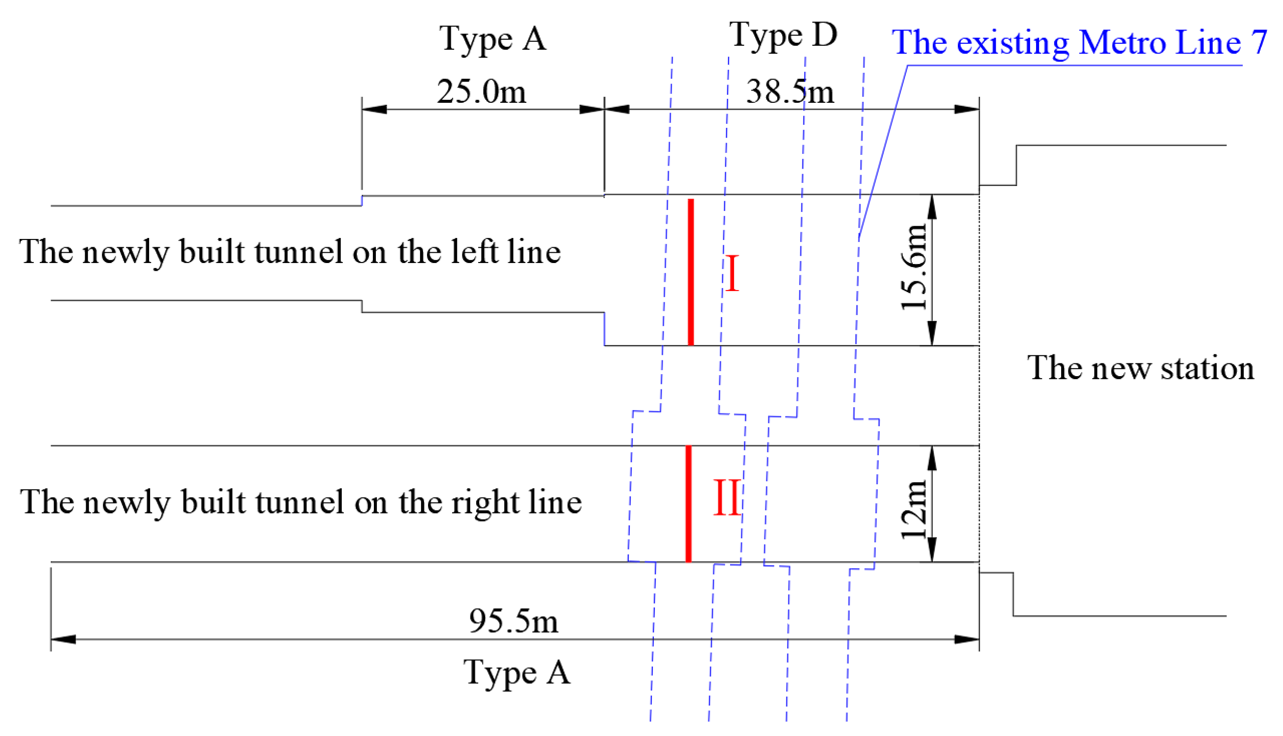
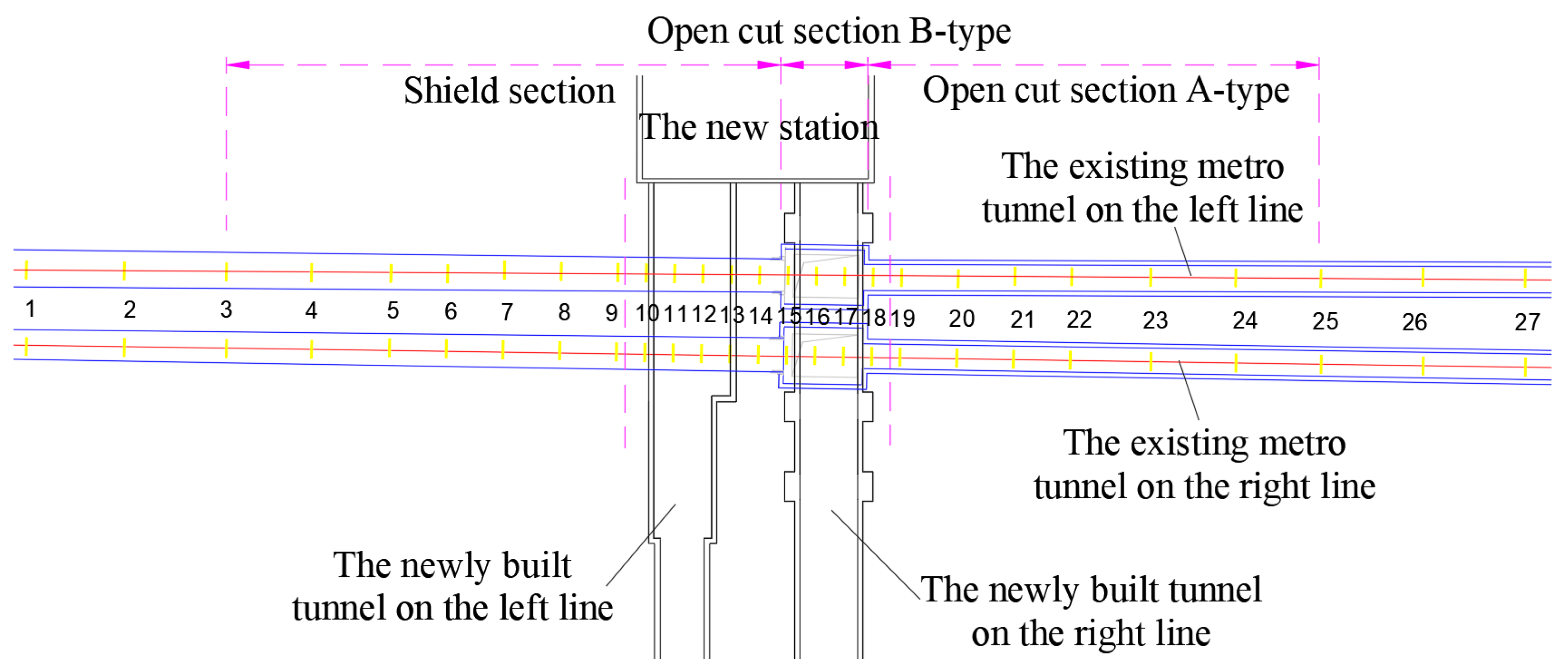
A new metro line has recently been completed in Guangzhou, China. In order to accommodate overtake lines for the skip-stop mode operation, two large-section mine tunnels were constructed in a business area located near the intersection of Panyu Avenue and Hanxi Avenue. These tunnels are surrounded by high-rise buildings and underground utility pipelines. They serve as connections between the main running tunnels and the new station. Moreover, these tunnels pass beneath two large subterranean commercial spaces and the existing metro Line 7, with depths ranging from 25.5 m to 31.5 m. The tunnel on the left line features a super large cross-section of 184 m
2, with a span of 15.6 m and a height of 14.8 m (Type D). On the other hand, the tunnel on the right line has a horseshoe shape, with a width of 12.6 m and a height of 11.6 m (Type A). The layout of these two tunnels is illustrated in
Figure 1.
2.2. Geological Conditions
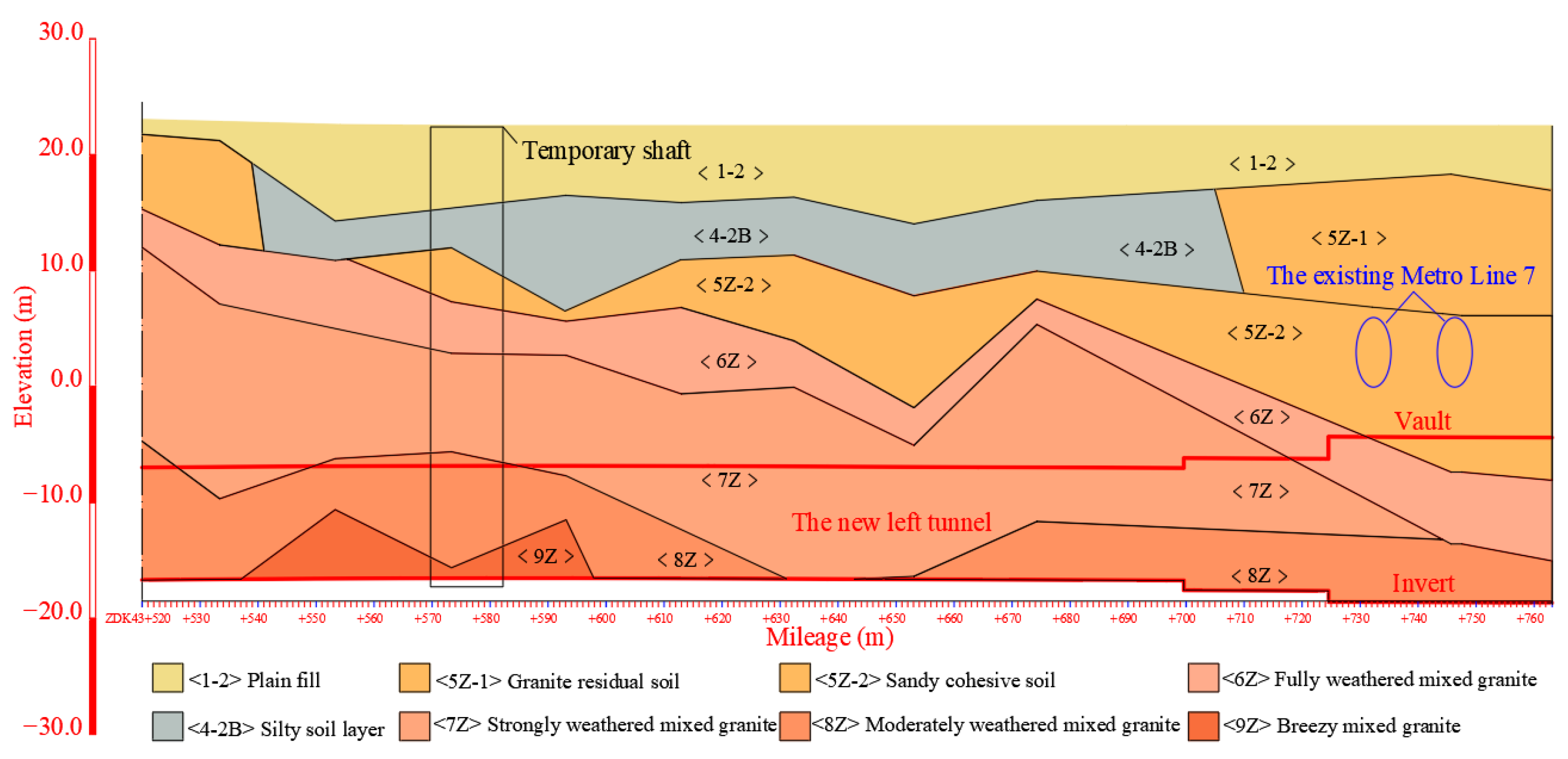
Figure 2 illustrates the geological stratification of the newly constructed mine tunnels. The stratigraphy can be generalized as plain fill (<1-2>) and a granite layer covered by silt (<4-2B>) below it. As the depth increases, the weathering degree of the granite layer gradually decreases (granite residual soul <5Z>, fully weathered mixed granite <6Z>, strongly weathered mixed granite <7Z>, moderately weathered mixed granite <8Z>. The main bodies of the tunnels are in fully to moderately weathered granite (<6Z>~<8Z>) and the partial tunnel crowns are located in the granite residual soil <5Z>.
Table 1 outlines the engineering parameters of the main strata.
Groundwater can be classified into two types based on its occurrence: Quaternary unconsolidated layer pore water and bedrock fissure water. The upper aquifer consists of perched water in plain fill <1>, and pore water in silt <4-2B> and a granite residual soil <5Z> layer, which also serve as confining layers separating the upper and lower aquifers due to low permeability. The lower fissure water of bedrock occurs mainly in the strong and moderately weathered mixed granite layer (<7Z>~<8Z>).
2.3. Tunnel Structure Design
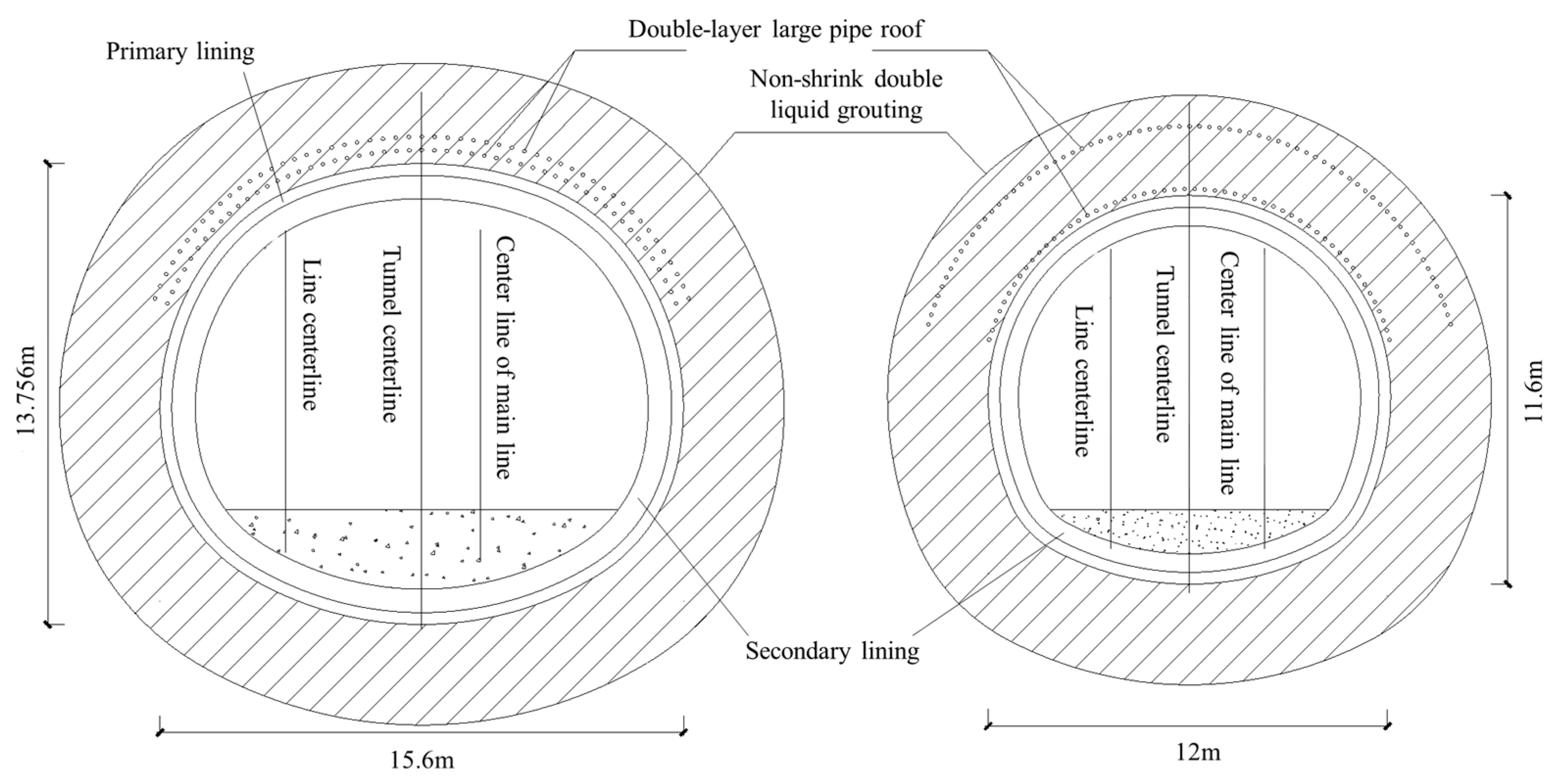
The main structure of the two new tunnels adopted composite lining. The advance support of the tunnel arch adopted a double-row large pipe shed with advance grouting of a small conduit. A non-shrink double liquid grouting technique was used in the tunnel to pre-reinforce the surrounding strata. The standard excavation step length was 0.5 m.
Figure 3 and
Table 2 outline the specific structural arrangement of the two mine tunnels.
3. Tunnel Construction
3.1. Excavation Plan
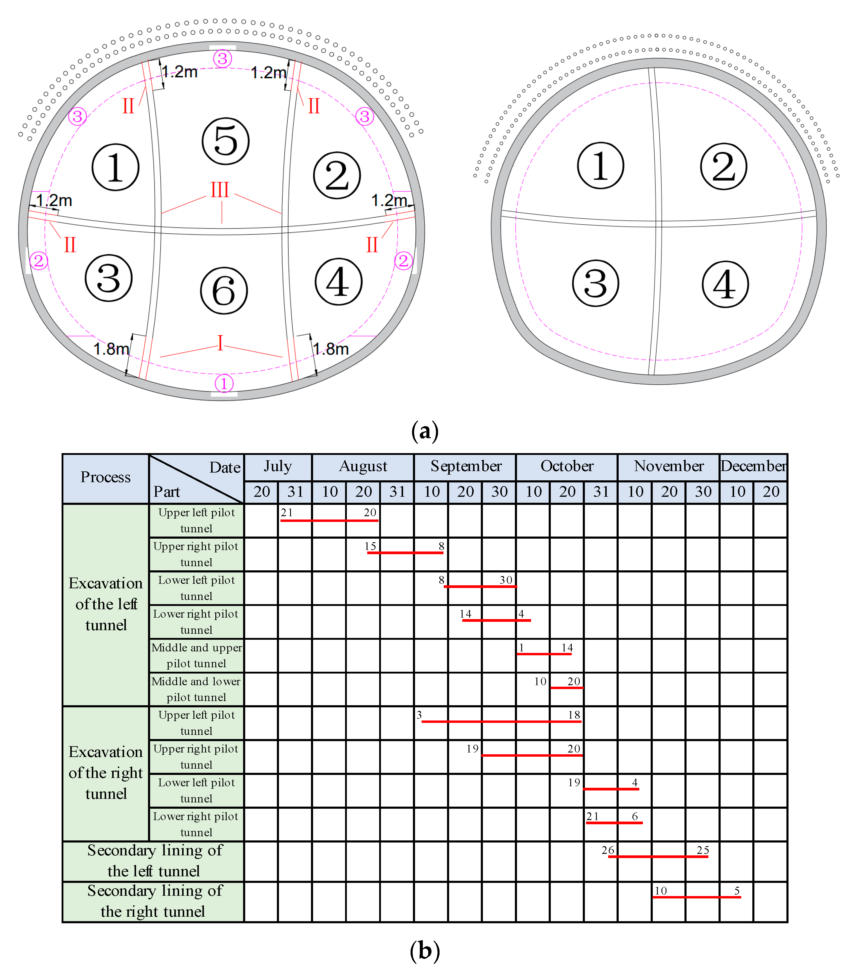
To reinforce surrounding soils and prevent water inrush, time consuming in-tunnel non-shrink double liquid grouting is required prior to excavation. At the same time, the soil excavations of the upper and lower pilot tunnels has a great influence on each other and the construction efficiency is low in the staggered construction of multiple pilot tunnels of large-cross-section tunnels. Therefore, to create extra working space and improve excavation efficiency, the construction scheme of the corresponding lower pilot tunnels in sequence are excavated after the upper pilot tunnels are excavated and connected has been adopted. Relevant construction planning is shown in
Figure 4a. The main construction procedures are as follows:
Step 1: excavating the top-left division of the left line;
Step 2: excavating the top-right division of the left line after excavation of 15 m in Step 1;
Step 3: excavating the bottom-left division of the left line and top-left division of the right line after the top-left division is excavated in Step 1;
Step 4: excavating the bottom-right division of the left line and the top-right division of the right line after the top-right division is excavated in Step 2;
Step 5: excavating the top-central division of the left line and the bottom-left division of the right line after the bottom-right division of the left line and the top-right division of the right line are excavated in Step 4;
Step 6: excavating the bottom-central division of the left line and the bottom-right division of the right line after excavation of 15 m in Step 5.
It is noted that the primary lining and temporary support were constructed immediately after each division was excavated, at an interval. The detailed construction schedule of the left- and right-line tunnels is presented in
Figure 4b.
3.2. Seconding Lining Construction and Removal of Temporary Diaphragm Supports
To control ground settlement and minimize uncertainty levels, the optimized scheme of constructing the secondary lining first and then removing the temporary support was adopted. The secondary lining was constructed at a longitudinal interval of 9 m. Taking the double side-wall drift (SD) method of the left tunnel as an example (see in
Figure 4a), the specific procedures are:
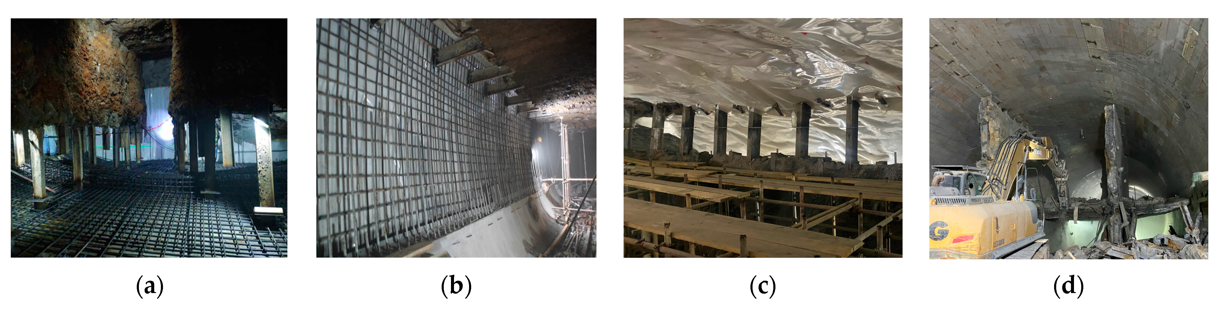
(1) The shotcrete with a height of 1.8 m at the bottom of the vertical diaphragm support range of the invert was removed, and the I-section exposed I-steel brace was cut off at every interval of an I-steel brace, as shown in
Figure 4a and
Figure 5a. Then, the invert of the secondary lining was constructed, including construction of the invert cushion, placement of the waterproof membrane, and molding of the reinforced concrete.
(2) The shotcrete with a width of 1.2 m (see in
Figure 4a) at the both ends of the horizontal diaphragm support range of the side walls was removed, and the II-section exposed I-steel brace was cut off alternately at the same frame of step (1). After that, the side walls of the secondary lining were constructed, as shown in
Figure 5b.
(3) The shotcrete with a height of 1.2 m at the top of the vertical diaphragm support range of the vault was removed, and the III-section I-steel brace was cut off alternately at the same frame of step (1). Then, the vault of the secondary lining was constructed as shown in
Figure 5c.
(4) After the secondary lining concrete reaches the design strength, the IV-section I-steel brace connected with the secondary lining was cut off and the remaining temporary diaphragm supports were demolished by the breaking hammer from top to bottom, as shown in
Figure 5d.
3.3. Grouting Lifting Measures
During the undercrossing construction, to control and adjust the settlement of the existing tunnel, a grouting platform was set at the end of the foundation pit of the new station. Grouting pipes were reserved above the advanced support of the new tunnel (interlayer soil between existing tunnel and new tunnel), and integrated drilling and grouting measures of non-shrink double liquid grouting were adopted.
According to the real-time monitoring settlement of the existing metro line, the ground under the track bed with settlement bigger than the limit value was reinforced by tracking grouting, and the existing metro tunnel structure was slowly lifted. The main component for grouting reinforcement was P042.5 cement, and the admixture was generally sodium bentonite. The grouting holes were arranged in a quincunx shape with three rows of grouting holes. The grouting pressure and grouting volume were controlled in real time according to the automatic monitoring data. The site’s horizontal tracking grouting lifting construction at the foundation pit of the new station is shown in
Figure 6.
4. Field Monitoring
4.1. Monitoring Purpose and Process
As described in
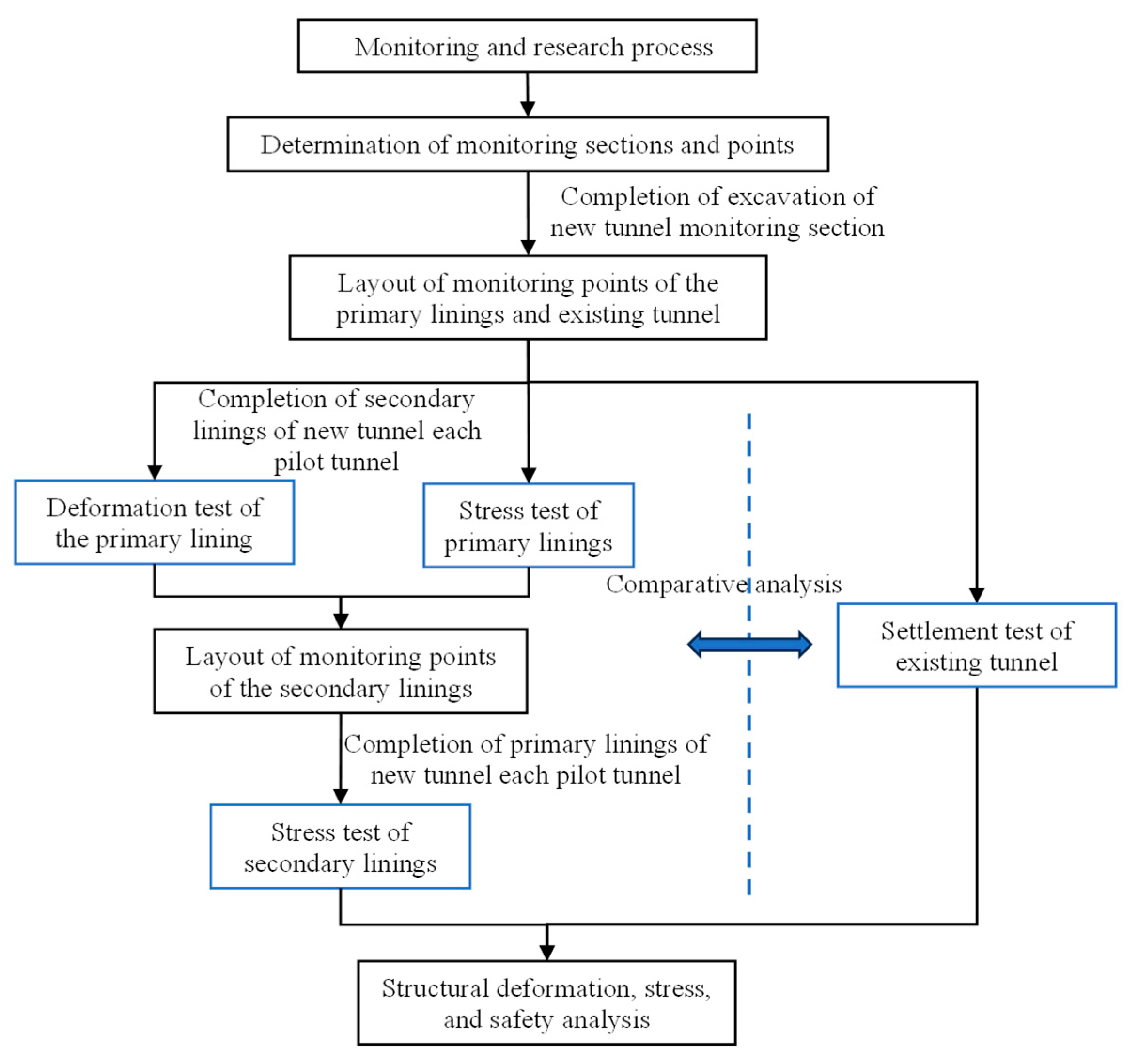
Section 3 of the article, the construction of the two tunnels was divided into multiple steps involving sophisticated mechanical transformation. Geochemical analysis also shows that granite residual soil, complete and severely weathered granite (<5Z>~<7Z>) in the area are prone to soften and disintegrate in water. Therefore, the existing metro line and other structures nearby could be easily disturbed during the construction of the two tunnels. As a result, extensive field monitoring was performed. Through on-site monitoring of stress and deformation of the new tunnel-supporting structure and settlement of the existing tunnel, it is possible to better understand the new tunnel support structure’s mechanical behavior, hence ensuring the safety of large-section tunnel construction and the existing tunnel at all phases. The flowchart of monitoring and research is shown in
Figure 7.
4.2. Field Monitoring Plan
In accordance with the structural arrangement and relative position between the newly constructed tunnels and the existing metro line above, Section I of the left-line tunnel, Section II of the right-line tunnel (as shown in
Figure 1) and the existing metro tunnel on the right line were selected for intensive monitoring. Specific monitoring items and testing methods are shown in
Table 3.
(1) Deformation test of the primary lining
After the excavation of the new tunnels, during the installation of the primary lining arch, steel reinforcement heads were pre-embedded. The steel reinforcement heads were buried in the soil from 30 to 50 cm, and after the shotcrete had solidified, the steel reinforcement heads were ensured to protrude by 3 to 5 cm. Subsequently, expansion bolts with hooks were welded onto the steel reinforcement heads. After the reflector was hung under the hook bolt, the elevation change of the primary lining structure in each pilot tunnel could be monitored through the total station, and the settlement of the vault and the arch waist could be measured. The monitoring time continued until the tunnels were broken through, and the settlement data was collected once a day. The settlement of the vault and arch waist was measured by monitoring the elevation change of the primary lining structure in each pilot tunnel. The specific layout of the measuring points is illustrated in
Figure 8.
(2) Stress test of primary and secondary linings
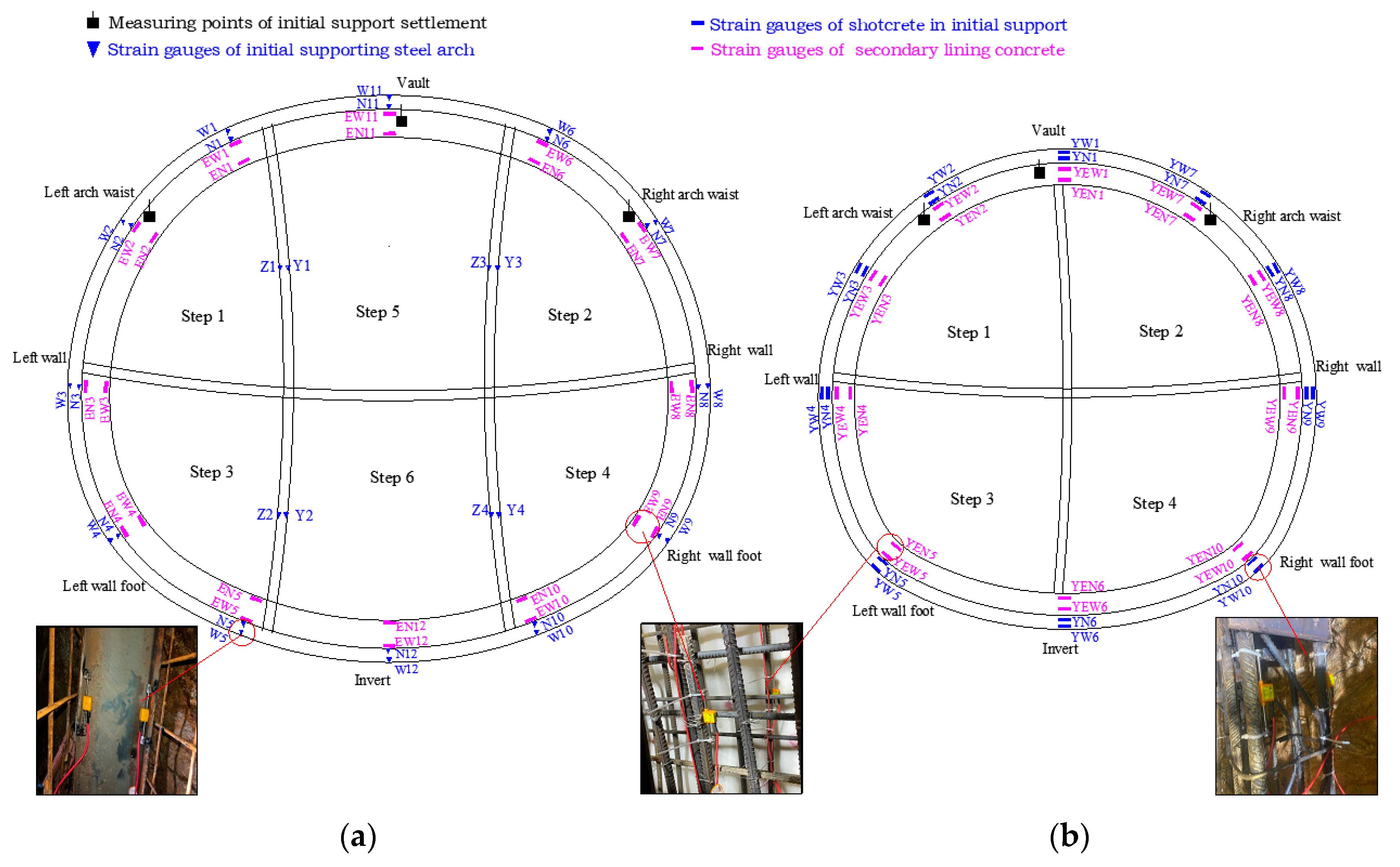
The left tunnel adopted I-25 steel frames for primary lining, with surface-mounted smart strain gauges welded on the upper and lower flanges of the steel frames. The right tunnel adopted grid steel frames for primary lining, with buried smart strain gauges tied and embedded at the upper and lower main reinforcement positions of the steel frames. The initial strain values were tested after the completion of primary lining shotcrete, and then the follow-up strain tests were carried out at a frequency of once a day. After the completion of secondary lining main reinforcement tying for both tunnels, smart strain gauges were tied and embedded at the corresponding cross-sections of the secondary lining at the upper and lower main reinforcement positions. The strain tests began after the completion of the secondary lining concrete pouring. Tests were conducted at a frequency of once a day. This enabled the acquisition of stress distribution and variation patterns in the primary and secondary linings during each construction stage through strain value calculation. Details of the monitoring setup are presented in
Table 3, while the layout of stress monitoring points is depicted in
Figure 8.
(3) Settlement test of existing tunnel
The monitoring of settlement and deformation in existing tunnel structures was carried out using automated static leveling methods. A horizontal line was established within the tunnel using a leveling instrument, and measurement points were marked along this line according to the design drawings. The measurement points were connected using four separate routes for water pipes, air pipes, signal cables, and power cables. Antifreeze fluid was injected into the water pipes starting from the first sensor until the pipes were completely filled with the fluid. After performing bubble elimination procedures twice, the last sensor’s water pipe was sealed. Then, a water tank was connected to the first sensor and fixed approximately 40 cm above the sensor. Finally, the measurement points were secured to the tunnel structure using M6 expansion bolts. Sedimentation data were collected automatically at a frequency of 2 h. The section of the measuring points layout and the position of the monitoring points in each section of the tunnel are shown in
Figure 9 and
Figure 10.
5. Monitoring Results and Analysis
It is evident that during the construction of the newly built tunnels, the existing metro line above will experience ongoing settlement. To mitigate this issue, deep-hole grouting was implemented above the new tunnels to control the settlement of the existing line. However, this measure can have a detrimental impact on the new tunnels below, especially when the primary lining has not yet been completed as a closed loop. Excessive deformation of new tunnels will adversely affect existing tunnels.
5.1. Deformation of Primary Lining
Figure 11 depicts the time evolution of accumulated settlements of the primary lining at the different positions. No valid data was collected at the arch crown of the left-line tunnel due to damages of sensors.
(1) Section I: The settlement gradually increased during the initial stages, but the rate of settlement increase began to accelerate due to the impact of deep-hole grouting, particularly when the bottom divisions were not completed. The primary lining structure deformed significantly due to the combined action of soil pressure and grouting pressure, with the maximum settlements recorded at the left and right waist being 120.8 mm and 127.1 mm, respectively. However, the settlements remained below the reserved deformation allowance of 150 mm.
(2) Section II: The construction of the right-line tunnel commenced approximately one month later than the left-line tunnel, and deep-hole grouting also had a significant influence on the deformation of the primary lining. The deformation of the primary lining increased sharply during the initial stages, reaching maximum values of 123.4 mm at the arch crown and 142.2 mm at the left waist. These values exceeded the reserved deformation allowance of 120 mm, and damage to the primary lining concrete was observed. The right waist was less affected by grouting, resulting in a final settlement of 77.3 mm. Due to the late excavation of the upper right pilot tunnel, part of the deep-hole grouting had been carried out before the construction of the pilot tunnel, so the settlement at the right arch waist was smaller. However, this also caused uneven settlement of the entire arch of the tunnel on the right. This would make the overall deformation and stress of the tunnel uneven, and the structural integrity would be affected.
(3) The grouting performed above the newly built tunnels had an adverse effect on the deformation of the primary lining, particularly when the lining structure was not fully completed as a closed loop and had low overall stiffness. Once the primary lining was completed, the settlement gradually stabilized. Improper control of grouting timing would cause a large deformation and uneven settlement of the tunnel arch, which would seriously affect the safety of the tunnel structure.
5.2. Stress Condition of Primary Lining
Structural strain at measuring points of Section I-II in
Figure 8 were also monitored, and stress could be calculated by multiplying the strain value and elastic modulus of relevant material. It was assumed that compression was negative and tension was positive, and the material adhered to the ideal elastic model. The time-dependent stress curves are depicted in
Figure 12 and
Figure 13.
5.2.1. Stress Variation of Primary Lining of the Left Line Tunnel
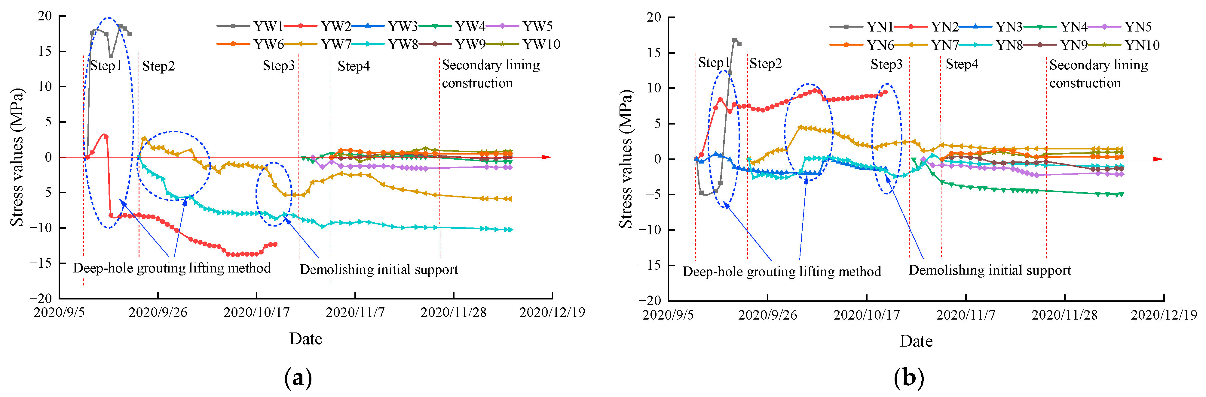
The time-dependent stress curves of the left tunnel at monitoring section I are depicted in
Figure 12. During the construction of the left tunnel, stresses of the primary lining steel frame fluctuated significantly. Upon the completion of Steps 1 and 2 (as shown in
Figure 8), the maximum compressive stress at measuring point W2 reached 158.8 MPa, influenced by the pressure of non-shrink double liquid grouting in the surrounding soil. The monitored stresses remained roughly stable until Steps 3 and 4 were carried out, with the top-left and right divisions being suspended. As a result, the stresses of primary lining and temporary support at the top division reduced with compression at some parts (Z1 and N2 in
Figure 7), and even swapped to tension. After the primary lining was completed as a closed loop, the stress condition stabilized. The hoop stress was predominantly in compression, with the stress level in the upper half significantly higher than that in the lower half, aligning well with engineering expectations. A maximum compression of 186 MPa and tension of 94 MPa were recorded at measuring points W7 and N7, respectively, and they were lower than the yield strength of steel (345 MPa).
Since the upper-left and upper-right pilot holes are excavated first, the primary lining was not completely closed at this time, and the primary lining bore the upper load under the grouting pressure generated by the upper deep-hole grouting. The left upper and right upper arches were in the middle of the initial arch beams, and the positions presented a tendency of the tunnel to bend inward under the action of the upper load. The outer compressive stress increased while the inner tensile stress increases. Therefore, the left and right arches of the tunnel were areas with high stress during construction, where the structures were weaker.
5.2.2. Stress Variation of Primary Lining of the Right Line Tunnel
Similar to the deformation curve of Section II, affected by grouting pressure above the tunnel, tensile stresses at certain positions of the arch crown (YW1, YN1, and YN2 as shown in
Figure 8) increased sharply at the initial stages, as in
Figure 13. The increased values were even bigger than the concrete tensile strength (1.78 MPa), so the fracture of the lining concrete was observed on site. Compared with those of the left-line tunnel, the stress value of the right-line tunnel was significantly lower. After the primary lining was completed as a closed loop, the maximum compressive stress value of 10.2 MPa and the maximum tensile stress value of 1.4 MPa were observed at the outer side of the right arch waist (YW8) and the inner side of the right arch waist (YN7), respectively. It is believed that damages in lining concrete led to stress redistribution and a significant portion of the internal forces was undertaken by the steel frame. The tunnel on the right line also had greater stress at the upper left and upper right arch waists due to the grouting pressure on the upper part, and the arch waists showed a tendency to bend inward. The bending of the arch waist caused the internal concrete of the primary support to crack, and the overall safety of the tunnel structure would also be reduced. However, since the right-line tunnel had a smaller cross-sectional area than the left-line tunnel, the arch beams of the tunnel were shorter and the stress on the structure would be smaller.
Deep-hole grouting was intended as a countermeasure to control excessive settlement of the existing metro line. However, it could have a significant adverse effect on the newly built tunnel lining, particularly when the primary lining is not fully completed. Relevant influence could be so severe that damages could be caused in the primary lining, compromising the newly built tunnel’s safety and stability. On the other hand, once the primary lining was completed as a closed loop, the stress condition tended to be stabilized and the impact from the deep-hole grouting would be much moderate.
5.3. Stress Condition of Secondary Lining
The stress condition of the secondary lining was also monitored with time-dependent stress curves depicted in
Figure 14 and
Figure 15.
5.3.1. Stress Variation of Secondary Lining of the Left Line Tunnel
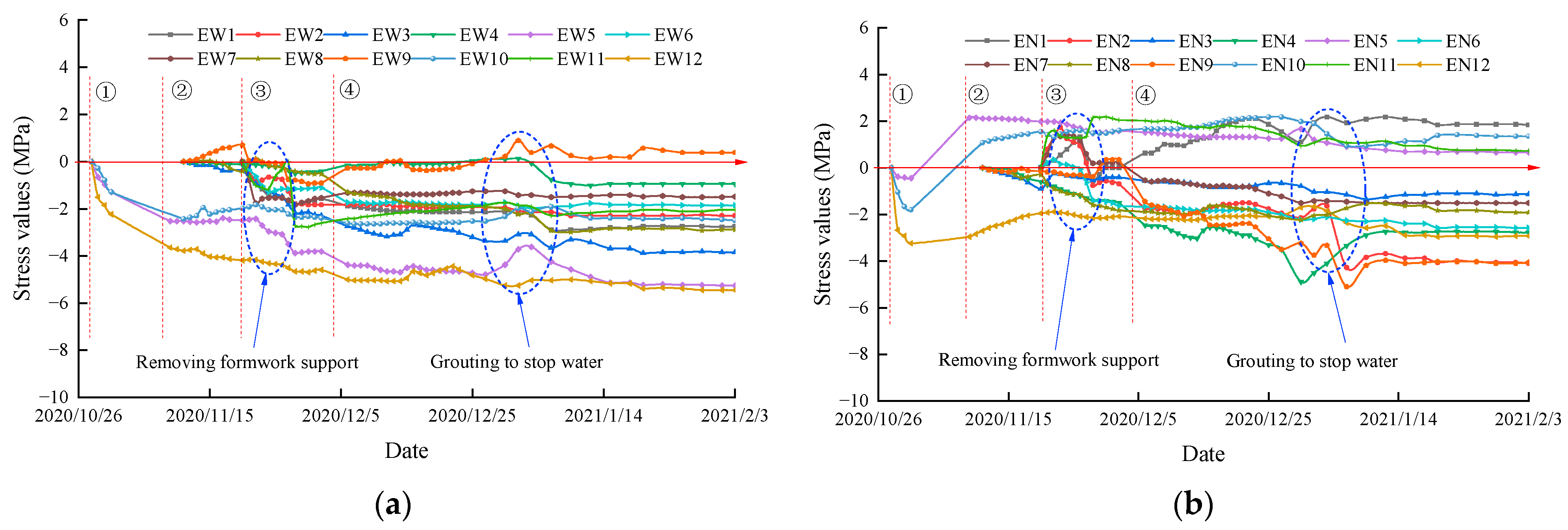
The secondary lining concrete of the left tunnel was poured symmetrically in sections. Pouring construction procedures were as follows: ① pouring of invert concrete; ② pouring of side-wall concrete; ③ pouring of vault concrete; ④ demolishing of bilateral partition walls (temporary invert). They correspond to phases ①~④ in
Figure 14.
(1) After the inverted arch concrete was finally set and the formwork was removed, the measuring points at the arch bottom (EW12/EN12) and foot (EW5/EN5, EW10/EN10) experienced compressive stress. However, due to the influence of construction machinery, formwork support, and other loads during construction, the compressive stress at points EN5 and EN10 changed to tensile stress. Similarly, after the side-wall concrete was set and the formwork was removed, the stress at each measuring point of the invert changed significantly due to the weight on the inverted arch structure. The inner side of the arch foot (EN5) experienced the largest tensile stress, reaching a maximum value of 2.14 MPa, close to the tensile strength value of C35 concrete (2.2 MPa). The outer side of the arch bottom (EW12) experienced the largest compressive stress, with a maximum value of 4.1 MPa, significantly lower than the compressive strength value of C35 concrete (23.4 MPa).
(2) After the arch concrete was set and the formwork was removed, the outer side of the secondary lining structure at each monitoring point experienced compressive stress, which continued to increase. On the other hand, the inner side of the vault (EN11), the left arch waist (EN1), and the arch foot (EN5, EN9, and EN10) experienced tensile stress. The removal of formwork support in the upper pilot tunnel caused significant changes in stresses in the upper half section, but they quickly stabilized.
(3) The complete removal of the middle partition wall and temporary invert resulted in a change in the stress system of the temporary support, significantly affecting the stress in the secondary lining structure. The stress on the inner side of the left arch waist (EN1) changed from compressive stress to tensile stress and gradually increased, reaching a maximum of 2.1 MPa. The tensile stress on the inner side of the right arch waist (EN7) and the right arch foot (EN9) changed to compressive stress, which rapidly increased and then reached a plateau.
(4) After the completion of the tunnel’s overall construction, local water-leakage positions in the secondary lining structure were sealed by grouting, which also influenced the stress in the structure. Starting from 18 January 2021, the structural stress values of the secondary lining in the left-line tunnel showed slight fluctuations and gradually stabilized. The largest tensile stress occurred on the inner side of the left arch waist (EN1) and stabilized at 1.8 MPa, while the largest compressive stress occurred on the outer side of the arch bottom (EW12) and stabilized at 5.4 MPa.
The stress variation in the secondary lining structure of the left-line tunnel exhibited a close correlation with each construction phase. The stress primarily originated from the self-weight of the lining concrete, the load imposed by formwork support, and the removal of temporary support during the pouring stage. Upon the completion of the full-ring concrete construction of the secondary lining and the removal of all temporary support systems, the stress distribution altered, accommodating a portion of the surrounding rock load. Nonetheless, the overall stress state remained relatively stable and fell within the acceptable range.
5.3.2. Stress Variation of Secondary Lining of the Right Line Tunnel
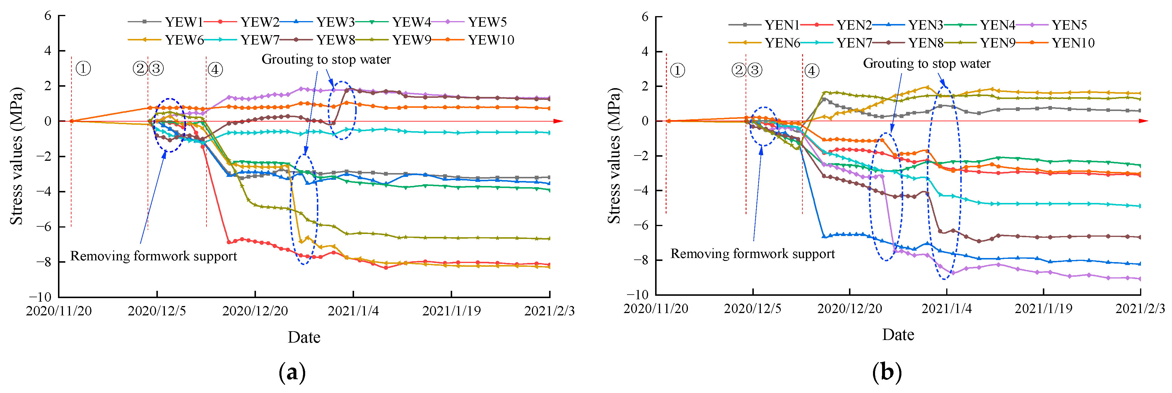
The secondary lining construction of the right-line tunnel mainly included three stages: pouring of lining (①~②), formwork removal of the full-ring lining (③) and the complete removal of the middle partition wall (④). They correspond to phases ①~④ in
Figure 15. Due to the constraints of the construction site, the strain of the right tunnel lining structure was monitored following the completion of concrete casting and the removal of the formwork.
(1) After the final setting and formwork removal of the full-ring concrete in the secondary lining, the stress variations in the structure were relatively gradual. Apart from the tensile stress observed at the measuring points on the outer side of the left arch foot (YEW5), the outer side of the right arch wall (YEW9), and the outer side of the right arch foot (YEW10), the remaining measuring points experienced compressive stress. The maximum tensile stress recorded on the outer side of the right arch foot (YEW10) was 0.69 MPa, while the maximum compressive stress on the inner side of the right arch wall (YEN9) was 1.58 MPa.
(2) Upon the complete removal of the middle partition wall and temporary invert, the support force in the middle of the lining disappeared instantaneously. The surrounding rock load redistributed onto the primary and secondary lining structures, resulting in a sharp change in stress at each measuring point. Except for the measuring points on the outer side of the right arch foot (YEW10), the left arch foot (YEW5) and the right arch wall (YEW8), the other measuring points on the outer side of the secondary lining structure experienced increasing compressive stress. The stress value at the outer side of the left arch waist (YEW2) was the highest, reaching approximately 6.87 MPa. The stresses on the inner side of the arch top (YNE1), arch bottom (YNE6), and right arch wall (YNE9) changed from compressive stress to tensile stress, with the maximum tensile stress observed at the inner side of the arch bottom (YEN6) reaching 1.6 MPa. The other measuring points on the inner side of the secondary lining structure experienced increasing compressive stress, with the most significant change occurring at the inner side of the left arch wall (YEN3), reaching 6.6 MPa.
(3) Following the completion of tunnel construction, grouting was performed to block water-leakage positions in the secondary lining structure, resulting in stress changes at certain measuring points. The compressive stress values at the outer side of the arch bottom (YEW6), outer side of the right arch wall (YEW8), inner side of the left arch foot (YEN5), and inner side of the right arch waist (YEN8) increased significantly. The tensile stress value at the outer side of the right arch waist (YEW8) showed the largest increase, from 0.1 MPa to 1.7 MPa. Starting from 18 January 2021, the stress values of the secondary lining structure in the right-line tunnel exhibited slight fluctuations and tended to stabilize. The largest tensile stress was observed on the inner side of the arch bottom (YEN6), stabilizing at 1.6 MPa, while the highest compressive stress occurred on the inner side of the left arch foot (YEN5), reaching 9.1 MPa.
The stress of the secondary lining structure in the right-line tunnel was affected by the removal of temporary support systems and the grouting and water plugging process behind the secondary lining, leading to significant stress changes. The primary lining structure adopted a grid steel frame, which has lower rigidity compared to the section steel frame. Consequently, after the removal of all temporary supports, the stress distribution changed, and both the primary and secondary lining structures bore the surrounding rock load simultaneously, resulting in a sharp increase in stress in the secondary lining structure. However, the stress levels at each measuring point remained within the acceptable range.
5.3.3. Internal Force of Secondary Lining
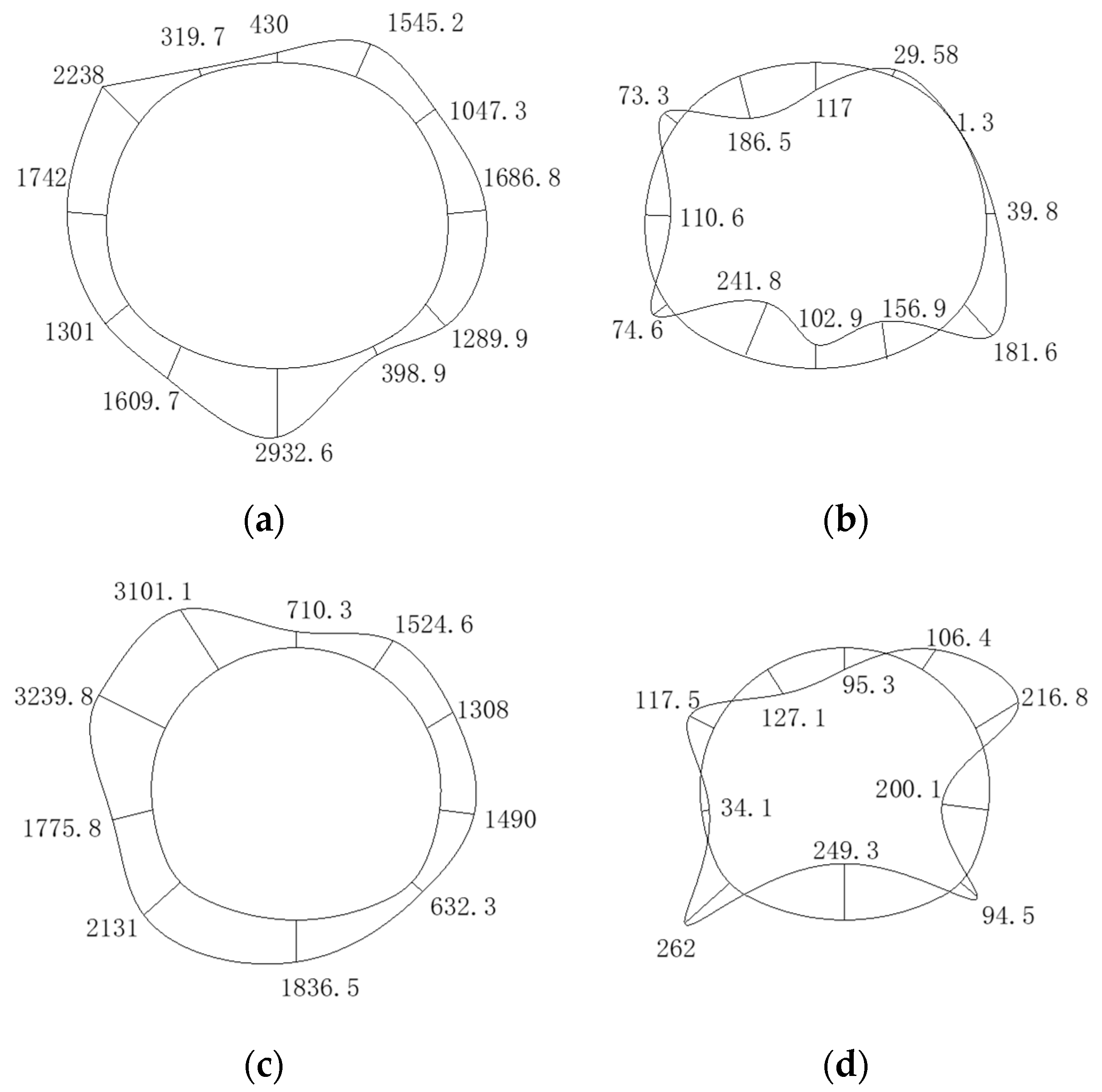
Internal forces of the secondary lining were calculated by integrating stresses over corresponding cross-sections and plotted in
Figure 16. For illustration purposes, axial compression was depicted as positive, and the bending moment was drawn on the tensile side of the structure. It can be observed that the internal forces of the secondary lining were roughly symmetrical along the centerline but strongly affected by construction and grouting procedures, which leads to large differences in the internal force at local area. As shown in
Figure 16a,b, the maximum axial compression and bending moment of the left-line tunnel were 2932.7 kN at the invert and 241.8 kN·m at the left side wall foot, respectively. Meanwhile, the maximum axial compression and bending moment of the right-line tunnel are 3239.8 kN at the left arch waist and 262 kN·m at the left side wall foot, respectively.
5.3.4. Safety Evaluation of Secondary Lining
With reference to relevant design codes [
20], safety factors at the measuring points along the secondary lining were calculated by dividing designed forces by section capacities, and the safety factor was checked to discover whether the safety criteria was satisfied. The minimum-strength safety factors of reinforced concrete structures given in the code are shown in
Table 4.
As depicted in
Figure 16, both newly built tunnels were deemed structurally safe, with a minimum safety factor calculated to be 2.9 times greater than the minimum safety factor in
Table 4. Patterns of the safety factors were similar between the two tunnels, with minimal safety factors locating at the left waist and the invert, as shown in
Figure 17a,b. In general, safety factors of the left-line tunnel were greater than those of the right tunnels, indicating that the left-line tunnel was structurally more conservative. This was reasonable, considering the super-span of 15.6 m in the left-line tunnel.
5.4. Settlement of Existing Tunnel Track Bed Structure
The settlement of the measuring point at the 10–18 section (as shown in
Figure 8) of the existing right-line tunnel located directly above the newly built tunnel is selected for analysis. The settlement changes in the existing metro right tunnel track-bed structure caused during the excavation of the large-section double-line tunnels are shown in
Figure 18.
According to
Figure 18, after the completion of the excavation of the two new tunnels, the maximum settlement of the existing right tunnel track bed was 85 mm, occurring in the area between the new left and right tunnels. The advanced non-shrink double liquid grouting of the tunnel face significantly disturbed the existing line, resulting in varying degrees of uplift of the existing tunnel track bed. During the construction of the new line of tunnels, the loss of soil and continuous dehydration constantly disturbed the strata, causing the existing tunnels to continue to sink. The effect of grouting lifting measures was closely related to the timing of the grouting. After the upper pilot tunnel was closed and formed into a loop, grouting could effectively lift the existing line, and the settlement value of the ballast bed was controlled within 20 mm. If the upper primary lining did not fall to the bottom of the stable formation, or the primary lining was not closed in time, grouting would press down on the new line structure, but intensify the sinking of the existing tunnel track bed. During the synchronous downward passage stage of the two tunnels, the excavation disturbance effect was superimposed, and the settlement rate of the existing line was the largest, causing a sharp increase in the settlement value of the ballast bed. The settlement rate decreased after the newly built left-line tunnel passes, and the settlement gradually tended to be stable after the newly built right-line tunnel passes through.
Once the timing of grouting lifting was not selected properly, when the primary lining was not closed in time during the excavation of the soil, the grouting pressure squeezed the upper primary lining structure of the new tunnel, causing the overall subsidence of the new tunnel. This would lead to simultaneous settlement of the upper strata and the existing tunnel, seriously affecting the structural safety.
6. Discussion
(1) The excavation sequence, bench length and excavation footage of each pilot tunnel of a large-section tunnel would affect the stress and deformation of the tunnel to a certain extent, and it would further affect the stability of the upper existing structure. The method of constructing the corresponding lower pilot tunnel in turn after the excavation and penetration of each upper pilot tunnel of the tunnel has been put forward in the actual construction on site, which reduces the mutual influence of the soil excavation of the upper and lower pilot tunnels to a certain extent. However, it also makes the time of the full-ring complete closure of the primary lining of each excavation section lag, which is not conducive to the stability of the new tunnel and the settlement and deformation control of the existing structure. Therefore, it is suggested that the tunnel excavation sequence should follow the conventional method of synchronously advancing the face after each pilot tunnel is staggered for a certain distance to ensure that the primary lining of the tunnel is closed in a timely manner. This is more conducive to the control of structural stress and deformation.
(2) When the large-section tunnel is excavated by the CRD method or double side-wall drift method, the tunnel stability is mainly maintained by the primary lining and temporary support, while the temporary support structure needs to be removed before the construction of the secondary lining structure. In this process, the large-section tunnel will lose the support from the temporary support structure and the surrounding rock pressure will be transferred to the primary lining, making the stress of the primary lining structure increase significantly. Once the removal method of support is improper, it may easily lead to the instability of the primary lining structure. At the same time, it will also cause great disturbance to the stratum and existing tunnel structure and affect the safety of the new and existing tunnels. In order to reduce the impact of support removal of a large-span tunnel, the optimization scheme of “lining first and removing braces later” is adopted (as introduced in
Section 3.2). This method greatly reduces the impact of the removal of the temporary support on the stability of the primary lining and effectively ensures the construction safety of the tunnel during the removal of the support.
(3) Deep-hole grouting lifting could be used as a countermeasure to control excessive settlement of the existing metro line above, but its application should be carefully arranged. If the primary lining is not fully completed as a close loop, the pressure from the deep-hole grouting can be harmful for the line structure. This would lead to increased settlement of new tunnels and the settlement of existing tunnels would continue to increase. The security of new and existing tunnels would be compromised. The grouting pressure should also be dynamically adjusted according to the real-time monitoring results of the newly built tunnels and the existing metro line. Extra care should be taken when both the cement slurry quantity and grouting pressure reach the maximum specified values.
7. Conclusions
Deformation and stress characteristics of primary lining structures of two large-section mine tunnels and settlement changes of existing tunnels were investigated using the field monitoring method. The stress variations, internal force distribution, and safety evaluation of the secondary lining were also discussed. Conclusions are as follows:
(1) Deep-hole grouting above a tunnel in construction could cause damage in the primary lining concrete and the existing tunnel above the newly built tunnel. It should be carefully applied. After primary lining is completed as a closed loop, settlement and stress condition of the lining structure tended to be stable, which was favorable for the control of structural deformation.
(2) Primary lining was most vulnerable structurally in the position of the arch waist on both sides of tunnels, and the stress condition of the upper-half lining was significantly more severe compared to that of the lower half.
(3) The left-line tunnel used a rigid steel frame for the primary lining, reducing stress changes during support removal after the secondary lining was completed. The right-line tunnel used a less rigid grid steel frame for initial support, resulting in a rapid transmission of load to the secondary lining after the removal of the partition wall, leading to a sharp change in its stress. Internal forces in the secondary lining were roughly symmetrical along the cross-section centerline but heavily affected by the construction sequence and measures.
(4) Safety factors of the left tunnel were higher than those of the right tunnel, indicating the left-line tunnel was structurally more conservative. This was reasonable for a tunnel with a super-large span of 15.6 m and situated in soil and rock layers sensitive to liquefaction.
Author Contributions
Conceptualization, L.Z. and G.C.; Methodology, Y.L. and S.G.; Software, G.C.; Validation, G.C. and S.G.; Formal analysis, Y.L. and S.W.; Investigation, L.Z. and G.C.; Resources, L.Z. and S.W.; Data curation, S.G. and L.L.; Writing—original draft preparation, L.Z., G.C., Y.L. and S.G.; Writing—review and editing, S.G.; Visualization, S.G. and G.C.; Supervision, L.Z.; Project administration, L.Z.; Funding acquisition, L.Z. All authors have read and agreed to the published version of the manuscript.
Funding
This research was supported by Advanced Engineering and Construction Technology Enterprise Key Laboratory for Urban Rail Transit of Guangdong Province, China, funding number 2017B030302009.
Institutional Review Board Statement
Not applicable.
Informed Consent Statement
Not applicable.
Data Availability Statement
Data are contained within the article.
Conflicts of Interest
The authors declare that they have no conflict of interest.
References
- Qu, W.B.; Liu, X.R.; Fu, Y.; Qin, X.Y. Numerical simulation of preliminary lining of large section crossing tunnels constructed with PBA method. Rock. Soil. Mech. 2009, 30, 2799–2804. [Google Scholar]
- Shahnazari, H.; Esmaeili, M.; Ranjbar, H.H. Simulating the Effects of Projectile Explosion on a Jointed Rock Mass Using 2D DEM: A Case Study of Ardebil-Mianeh Railway Tunnel. Int. J. Civ. Eng. 2010, 8, 125–133. [Google Scholar]
- Chen, S.Q.; Jin, X.G.; Jin, Y.J.; Zhu, L. Tunnel Supporting Structure Stress and Displacement Characteristics Research. Appl. Mech. Mater. 2011, 90–93, 1454–1460. [Google Scholar] [CrossRef]
- Zhu, Y.P.; Song, X.R. Stress Analysis about Flat Ratio and Surrounding Rock of Large Section Highway Tunnel. Appl. Mech. Mater. 2013, 368–370, 1404–1409. [Google Scholar] [CrossRef]
- Li, Y.; Jin, X.; Lv, Z.; Dong, J.; Guo, J. Deformation and mechanical characteristics of tunnel lining in tunnel intersection between subway station tunnel and construction tunnel. Tunn. Undergr. Sp. Tech. Incorpor. Trench. Tech. Res. 2016, 56, 22–33. [Google Scholar] [CrossRef]
- Li, P.F.; Zhang, D.L.; Zhao, Y.; Zhou, Y.; Fang, Q.; Zhang, X. Study of mechanical characteristics of secondary lining of large-section loess tunnel. Chin. J. Rock Mech. Eng. 2010, 29, 1690–1696. [Google Scholar]
- Lu, L. Construction techniques for large cross-section tunnels of a metro crossover line in loess stratum. Traffic Eng. Tech. Natl. Def. 2021, 19, 32–36. [Google Scholar]
- Han, X.M.; Sun, M.L.; Zhu, Y.Q. Study on Section Shape and Support Parameters of Guanjiao Tunnel under Carbonaceous Slate Stratum of the 2nd Line between Xining and Golmud. Adv. Mater. Res. 2011, 261–263, 1699–1704. [Google Scholar] [CrossRef]
- Li, W.H.; Zhao, D.J.; Zhou, S.S. Numerical Simulation Analysis and Engineering Applications on the Double-Side-Wall Heading Step Bench Excavation of Large-Cross Section and Shallow Tunnel. Adv. Mater. Res. 2012, 594–597, 1182–1187. [Google Scholar] [CrossRef]
- Lei, J.S.; Yang, J.S.; Yang, F.; Zeng, S. In-situ monitoring and mechanical analysis of large-span unsymmetrical loading multi-arch tunnel. J. Railw. Sci. Eng. 2010, 7, 31–36. [Google Scholar]
- Zhang, H.L.; Yang, J.S.; Gou, D.M. Application of sensor in long-term stress monitoring of multiple-arch tunnel under highway. Trans. Microsyst. Technol. 2011, 30, 146–148. [Google Scholar]
- Wang, S.; Yang, J.; Peng, T. Field measurement of stresses and safety evaluation of eight-lane framed lake tunnel with the cut-and-cover method. Chin. Civ. Eng. J. 2014, 47, 120–127. [Google Scholar]
- Ma, X.M. Test research on the stress characteristics of the large section expansive soil tunnel. J. Railw. Eng. Soc. 2018, 35, 63–69. [Google Scholar]
- Gong, Y.F.; Zhang, J.R.; Xu, X.D.; Tang, Z. Design technology for super large cross section tunnel in stratum of completely weathered granite with abundant water. J. Railw. Eng. Soc. 2015, 32, 79–85+92. [Google Scholar]
- Yan, L.; Zhang, Z.; Yang, J.S. Application of sensor in structure monitoring of large-span tunnel underpass high-voltage power transmission tower. Trans. Microsyst. Technol. 2015, 34, 151–154. [Google Scholar]
- Chen, J.J.; Yang, Y.H.; Yang, J.S.; Zhang, X.M. Field measurement and analysis of large section tunnel penetrating high voltage transmission tower. J. China Foreign Highw. 2015, 35, 185–189. [Google Scholar]
- Cao, C.Y.; Shi, C.H.; Peng, L.M.; Lei, M.F.; Tan, Y. Analysis of the Mechanical Behaviors of Shallow-Buried Large-Span Tunnels under Expressways. Mod. Tunnel. Technol. 2017, 54, 122–129, 154. [Google Scholar]
- Zhou, W. Scheme optimization and monitoring analysis of large section shallow buried tunnel on existing highway. J. Xi'an Univ. Arch. Tech. (Nat. Sci. Ed.) 2020, 52, 520–527. [Google Scholar]
- Luo, Y.; Chen, J.; Shi, Z.; Li, J.; Liu, W. Mechanical characteristics of primary support of large span loess highway tunnel: A case study in Shaanxi Province, Loess Plateau, NW China primary. Tunn. Undergr. Sp. Tech. 2020, 104, 103532. [Google Scholar] [CrossRef]
- Industrial Standard of the People's Republic of China. Code for Design of Railway Tunnel: TB 10003-2016; China Railway Publishing House: Beijing, China, 2016; pp. 47–59.
Figure 1.
Plan layout of two large-section mine tunnels.
Figure 1.
Plan layout of two large-section mine tunnels.
Figure 2.
Geology profile of the left tunnel.
Figure 2.
Geology profile of the left tunnel.
Figure 3.
Plan layout of two large-section mine tunnels.
Figure 3.
Plan layout of two large-section mine tunnels.
Figure 4.
Construction process and progress of left tunnel (double side-wall drift (SD) method): (a) Schematic diagram of construction procedures; (b) Horizontal chart of construction schedule.
Figure 4.
Construction process and progress of left tunnel (double side-wall drift (SD) method): (a) Schematic diagram of construction procedures; (b) Horizontal chart of construction schedule.
Figure 5.
Secondary lining construction processes: (a) Removal of bottom portion of shotcrete and I-beam braces; (b) Construction of secondary lining side walls; (c) Construction of secondary lining vault; (d) Removal of remaining temporary supports.
Figure 5.
Secondary lining construction processes: (a) Removal of bottom portion of shotcrete and I-beam braces; (b) Construction of secondary lining side walls; (c) Construction of secondary lining vault; (d) Removal of remaining temporary supports.
Figure 6.
Construction drawing of foundation pit horizontal tracking grouting lifting measures.
Figure 6.
Construction drawing of foundation pit horizontal tracking grouting lifting measures.
Figure 7.
Flowchart of monitoring and research.
Figure 7.
Flowchart of monitoring and research.
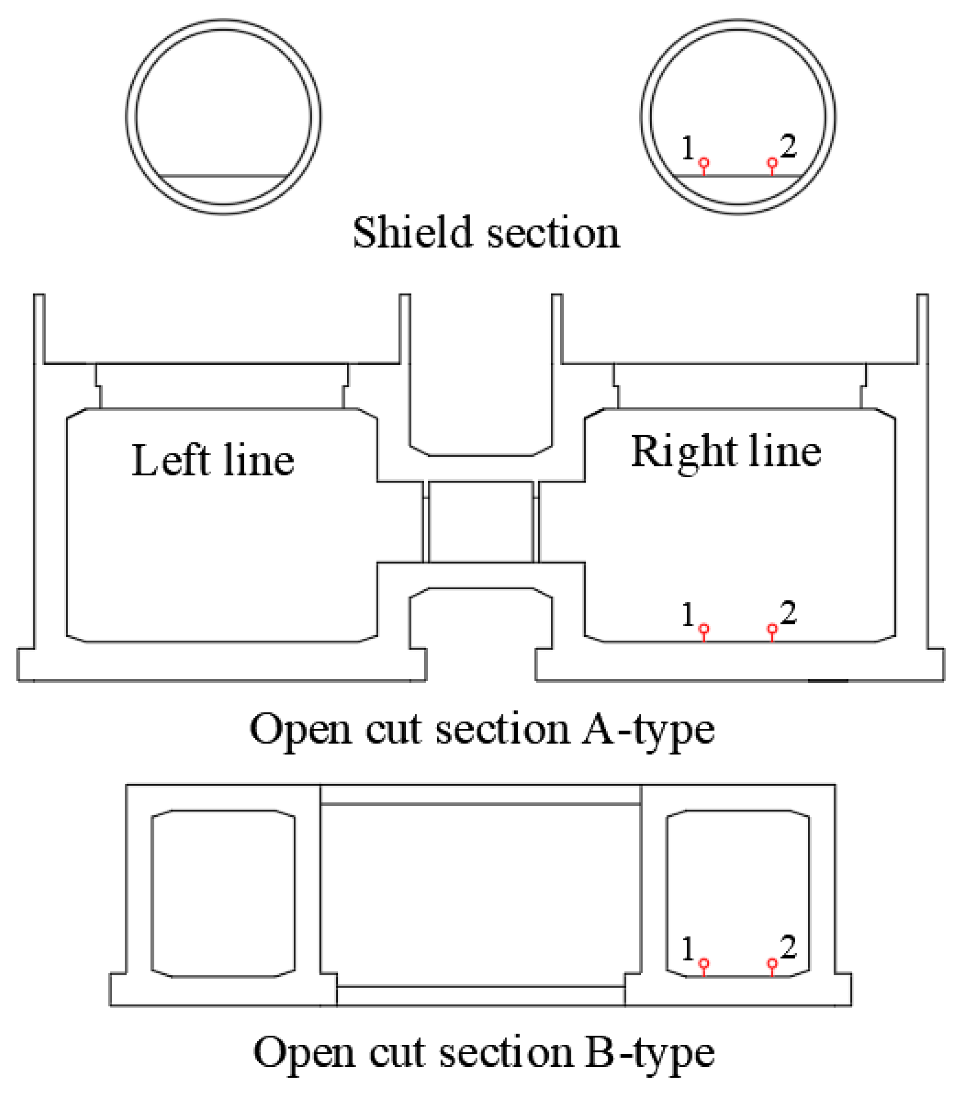
Figure 8.
Layout of measuring points of stress monitoring section of support system: (a) Monitoring section I of the left tunnel; (b) Monitoring section II of the right tunnel. (Note: “W” refers to the strain gauge number outside the initial support; “N” refers to the strain gauge number inside the initial support; “EW” indicates the number of the strain gauge embedded outside the secondary lining; “EN” indicates the number of the strain gauge embedded inside the secondary lining).
Figure 9.
Layout of monitoring sections of existing metro tunnel on the right line.
Figure 9.
Layout of monitoring sections of existing metro tunnel on the right line.
Figure 10.
Layout of monitoring points in different sections of existing metro tunnels.
Figure 10.
Layout of monitoring points in different sections of existing metro tunnels.
Figure 11.
Curve of cumulative settlement of initial support structure of newly built tunnels with time: (a) Test section I of the left tunnel; (b) Test section II of the right tunnel.
Figure 11.
Curve of cumulative settlement of initial support structure of newly built tunnels with time: (a) Test section I of the left tunnel; (b) Test section II of the right tunnel.
Figure 12.
Time-dependent stress curve of initial supporting structure at monitoring section I: (a) External stress; (b) Internal stress.
Figure 12.
Time-dependent stress curve of initial supporting structure at monitoring section I: (a) External stress; (b) Internal stress.
Figure 13.
Time-dependent stress curve of initial supporting structure at monitoring section II: (a) External stress; (b) Internal stress.
Figure 13.
Time-dependent stress curve of initial supporting structure at monitoring section II: (a) External stress; (b) Internal stress.
Figure 14.
Time-dependent stress curve of secondary lining structure of the left tunnel: (a) External stress; (b) Internal stress.
Figure 14.
Time-dependent stress curve of secondary lining structure of the left tunnel: (a) External stress; (b) Internal stress.
Figure 15.
Time-dependent stress curve of secondary lining structure of the right tunnel: (a) External stress; (b) Internal stress.
Figure 15.
Time-dependent stress curve of secondary lining structure of the right tunnel: (a) External stress; (b) Internal stress.
Figure 16.
Internal force distribution of newly built tunnels in the secondary lining: (a) Axial force of the left tunnel(kN); (b) Bending moment of the left tunnel(kN·m); (c) Axial force of the right tunnel(kN); (d) Bending moment of the right tunnel(kN·m).
Figure 16.
Internal force distribution of newly built tunnels in the secondary lining: (a) Axial force of the left tunnel(kN); (b) Bending moment of the left tunnel(kN·m); (c) Axial force of the right tunnel(kN); (d) Bending moment of the right tunnel(kN·m).
Figure 17.
Distribution of safety factor of newly built tunnels’ secondary lining: (a) Safety factor of secondary lining of the left tunnel; (b) Safety factor of the secondary lining of the right tunnel.
Figure 17.
Distribution of safety factor of newly built tunnels’ secondary lining: (a) Safety factor of secondary lining of the left tunnel; (b) Safety factor of the secondary lining of the right tunnel.
Figure 18.
Settlement curve of existing right tunnel track bed with time.
Figure 18.
Settlement curve of existing right tunnel track bed with time.
Table 1.
Stratum engineering parameters.
Table 1.
Stratum engineering parameters.
| Stratum Name | Density
(kg·m−3) | Elastic Modulus
(MPa) | Poisson’s Ratio | Cohesion
(kPa) | Internal Friction
Angle (°) | Permeability Coefficient
(m·d−1) | Void Ratio |
|---|
| <1-2> Plain fill | 1850 | 5 | 0.3 | 12 | 7 | 0.2 | 0.88 |
| <5Z-1> Granite residual soil | 1850 | 20 | 0.35 | 25 | 21 | 0.1 | 0.69 |
| <5Z-2> Sandy cohesive soil | 1890 | 22 | 0.28 | 27 | 24 | 0.1 | 0.70 |
| <6Z> Fully weathered mixed granite | 2100 | 70 | 0.27 | 35 | 25 | 0.2 | 0.60 |
| <7Z> Strongly weathered mixed granite | 2300 | 85 | 0.23 | 45 | 30 | 0.8 | 0.55 |
| <8Z> Moderately weathered mixed granite | 2500 | 5000 | 0.2 | 400 | 35 | 0.8 | 0.01 |
Table 2.
Supporting structure parameters.
Table 2.
Supporting structure parameters.
| Type | Items | Materials Specification | Detail |
|---|
| Surrounding soil reinforcement | Non-shrink double liquid grouting | Mixture of water glass and phosphoric acid and mixture of water glass and cement slurry | The scope of grouting: All mixed granite residual soil and completely weathered/strongly weathered mixed granite strata within the tunnel face and 3 m outside the excavation contour line |
Advanced
support | Advanced large pipe roof | Left line tunnel: 159-mm-diameter, 47-m-long seamless steel pipes with wall thickness of 8 mm
Right line tunnel: 108-mm-diameter, 47-m-long seamless steel pipes with wall thickness of 6 mm | Left line tunnel: Set within 130 degrees of the tunnel top floor, double layers arrangement, inner pipe roof with 0.35-m circular distance and 0.4-m distance to the excavation contour, outer pipe roof with 0.37-m circular distance and 0.8-m distance to the excavation contour
Right line tunnel: Set within 150 degrees of the tunnel top floor, double-layer arrangement, inner pipe roof with 0.31-m circular distance and 0.4-m distance to the excavation contour, outer pipe roof with 0.315-m circular distance and 2.8-m distance to the excavation contour |
| Advanced small pipe | 42-mm-diameter, 3.5-m-long seamless steel pipes with wall thickness of 3.5 mm | Set within 180 degrees of the top floor of each tunnel with 0.3-m circular distance, 2.5-m longitudinal distance |
Primary
lining | Shotcrete | C25, P6 early strength shotcrete | 0.35 m thick for primary supports and temporary supports |
| Steel mesh | 8-mm-diameter steel bars | 150 mm (longitudinal) × 150 mm (circular), full circular double layers arrangement |
| Steel arch centering | Left line tunnel: I-25, Q345 steel beam centering
Right line tunnel: 25-mm-diameter four main steel bars lattice girder | 0.5-m longitudinal distance |
| Rock bolt | 25-mm-diameter, 3.5-m-long hollow bolt with wall thickness of 3.5 | 1-m circular distance, 0.5-m longitudinal distance, quincunx arrangement |
Secondary
lining | Reinforced concrete | C35, P12 reinforced concrete | Left line tunnel: wall thickness of 0.7 m
Right line tunnel: wall thickness of 0.55 m |
Table 3.
Field monitoring items and testing methods.
Table 3.
Field monitoring items and testing methods.
| Step | Monitoring Items | Monitoring Sensors | Measuring Instrument | Quantity |
|---|
| 1 | Arch settlement of newly built tunnel | Expansion bolt | Electronic Total Station | 6 |
| 2 | Initial support steel arch strain of newly built left-line tunnel | JMZX-212H
vibrating wire strain gauge | JMZY-2003
Strain meter | 16twain |
| 3 | Initial support shotcrete strain of newly built right-line tunnel | JMZX-215HAT
vibrating wire embedded strain gauge | 10twain |
| 4 | Secondary lining concrete strain of newly built left-line tunnel | 12twain |
| 5 | Secondary lining concrete strain of newly built right-line tunnel | 10twain |
| 6 | Settlement of existing tunnel track bed on the right line | Smart liquid level sensor
Liquid storage tank | Static Leveling System | 54 |
Table 4.
Strength safety factor of reinforced concrete structures.
Table 4.
Strength safety factor of reinforced concrete structures.
| | Load Combination | Main Load | Main Load and
Additional Load |
|---|
| Damage Reason | |
|---|
| Reaching of reinforcement calculated strength/Reaching of concrete ultimate compressive or shear strength | 2.0 | 1.7 |
| Reaching of concrete ultimate tensile strength | 2.4 | 2.0 |
| Disclaimer/Publisher’s Note: The statements, opinions and data contained in all publications are solely those of the individual author(s) and contributor(s) and not of MDPI and/or the editor(s). MDPI and/or the editor(s) disclaim responsibility for any injury to people or property resulting from any ideas, methods, instructions or products referred to in the content. |
© 2023 by the authors. Licensee MDPI, Basel, Switzerland. This article is an open access article distributed under the terms and conditions of the Creative Commons Attribution (CC BY) license (https://creativecommons.org/licenses/by/4.0/).


