Article

Bio-Induced Healing of Cement Mortars in Demineralized and Danube Water: CNN Model for Image Classification

1
Mining Institute Ltd. Belgrade, Batajnički put 2, Zemun, 11080 Belgrade, Serbia
2
Mining and Metallurgy Institute Bor, Zeleni bulevar 35, 19210 Bor, Serbia
3
Laboratory for Materials in Cultural Heritage, Faculty of Technology, University of Novi Sad, Bulevar Cara Lazara 1, 21000 Novi Sad, Serbia
4
Technical Faculty in Bor, University of Belgrade, Vojske Jugoslavije 12, 19210 Bor, Serbia
*
Author to whom correspondence should be addressed.
Buildings 2023, 13(7), 1751; https://doi.org/10.3390/buildings13071751
Submission received: 8 June 2023 / Revised: 29 June 2023 / Accepted: 5 July 2023 / Published: 10 July 2023
(This article belongs to the Special Issue Functional and Smart Materials for Buildings and Constructions)

Abstract

:
Reducing the costs of repairing concrete structures damaged due to the appearance of cracks and reducing the number of people involved in the process of their repair is the subject of a multitude of experimental studies. Special emphasis should be placed on research involving industrial by-products, the disposal of which has a negative environmental impact, as is the case in the research presented in this paper. The basic idea was to prepare a mortar with added granulated blast furnace slag from Smederevo Steel Mill and then treat artificially produced cracks with a Sporosarcina pasteurii DSM 33 suspension under the conditions of both sterile demineralized water and water from the Danube river in order to simulate natural conditions. The results show a bio-stimulated healing efficiency of 32.02% in sterile demineralized water and 42.74% in Danube river water already after 14 days. The SEM images clearly show calcium carbonate crystals as the main compound that has started to fill the crack, and the crystals are much more developed under the Danube river water conditions. As a special type of research, microscopic images of cracks were classified into those with and without the presence of bacterial culture. By applying convolutional neural networks (ResNet 50), the classification success rate was 91.55%.

1. Introduction

Concrete is formed by a mixture of cement, coarse, and fine aggregate with water. Cement in this mixture plays an essential role by connecting aggregates, filling the space between them [1]. No building can be imagined without the use of concrete, and for this reason, concrete is the most widely used building material. Good concrete properties are primarily reflected in extremely high compressive strength, market availability, pourability into various forms, price, etc. However, despite its good properties, this material has high cracking sensitivity due to its limited tensile strength. For this reason, it is often combined with steel reinforcement, which allows it to bear certain tensile loads. However, steel reinforcement cannot prevent crack formation but can only limit crack width. Cracks that appear over time are the result of various environmental influences to which building structures are exposed. Various aggressive liquids and gases can penetrate the cement matrix through these cracks. In the worst-case scenario, when the steel reinforcement is exposed to environmental influences, it can corrode and get severely damaged at the crack site. Such severe damages to building structures require repairs, which makes maintenance even more expensive. According to available data for Great Britain, the annual costs of maintenance and repair of building structures exceed 40 billion pounds, while the USA plans to invest about 4.59 billion dollars in the next three years for their repairs [2,3,4,5]. In addition to the economic impact, this also raises the issue of environmental protection through the conservation of resources and waste problems. However, the occurrence of damage does not necessarily cause major problems. Even a minor cost reduction in repairing cracks and damage to building structures makes a difference in the economy and ecology of every country, especially if performed without human intervention [6,7,8,9,10,11].
For more than fifty years, there has been the idea of finding new, smart, cement-based materials that have the ability to increase the self-healing properties of concrete. Self-healing materials should be cheap and not affect the properties of concrete structures and the most important thing, is that they should be active for a long time, as cracks usually do not appear immediately after installation. These materials could at least partially if not completely, reduce the appearance of damage while maintaining the initial structure properties and prevent the formation of subsequent permanent cracks that would further weaken the building [3,4,5,6].
The basic concept of self-healing materials in construction is to restore concrete strength, porosity, workability, and waterproofing [12]. Certainly, using building materials with self-healing properties would require more significant financial investments at the very beginning but they would still bring savings over time [13].
The self-healing phenomenon is defined by the material’s ability to heal small cracks on its own without external human intervention [13,14].
Self-healing of concrete can be greatly contributed by the presence of certain mineral additives such as fly ash, blast furnace slag, silica fume, limestone powder, geomaterials, etc. These materials are added as additives, since they stimulate autogenous healing, especially in the later phase due to the slower pozzolanic reaction of non-hydrated binders [13,15]. In the presence of water, pozzolanic materials react with portlandite (Ca(OH)2), forming binding products, and calcium carbonate [15].
Granulated blast furnace slag and fly ash, as industrial by-products, are an inexhaustible research topic as cement additives, and the reason for this is primarily their pozzolanic activity. In their cement matrix self-healing experiments, Li et al. (2020) only used granulated blast furnace slag in different mass ratios, with added crystalline admixtures. Their results showed that mortar with 10% granulated blast furnace slag and crystal additives demonstrated self-healing properties where calcium carbonate was the product that healed the crack [16,17].
Moreover, calcium carbonate precipitation is a common natural phenomenon. In addition to being found in nature (earth crust, sea, and fresh water), calcium carbonate is a raw material for obtaining cement, which makes it one of the most useful building materials. Besides that they form a wide range of minerals, carbonates are known to be produced by certain microorganisms, especially bacteria, and due to their crack-filling efficiency, they are used as one of the significant external self-healing methods for cement materials. Metabolic activities in the bacterial self-healing process lead to carbonate production, when carbonate ions react with calcium ions from the material, resulting in calcium carbonate formation due to system oversaturation [18]. In this way, cracks and gaps created as a result of concrete structure damage are filled. Introducing microorganisms into the self-healing process requires great care since many factors affect their metabolic activity. For example, a lack of sufficient moisture and a high pH are destructive to the bacteria metabolic activity [1].
Since concrete structures are designed to last over 100 years, the bacteria should survive and remain active during that period in a highly alkaline environment. In their investigation, Renée and Henk (2012) presented the conclusions of Jose-Luis and Aylin (1996) about bacterial viability over a long period and under different conditions. Based on extensive research, it was found that bacteria are produced from thick-walled spores. These spores are resistant to chemical and mechanical influences and can remain dormant for a very long time. In conditions of concrete structure cracks with food and water present, the spores germinate and transform into active bacteria and their metabolic products can fill the free crack space [6,19].
In recent years, a special approach to research through connecting experiments with numerical simulations and modeling has attracted a lot of attention from researchers, whether it is classical or artificial intelligence methods (such as forming mathematical equations that describe the trend of crack healing, predicting the effectiveness of crack healing based on their dimensions, the classification of data based on the appearance of samples, etc.) [8,10,20,21].
Considering that there are bridges of exceptional cultural, historical, and symbolic value, the state of damage of their concrete structures in real conditions was the subject of many authors, especially after natural disasters caused by earthquakes. Mangalathu et al. (2019) proposed a methodology that includes a rapid assessment of the state of damage using the capabilities of machine learning techniques (e.g., Discriminant Analysis (QDA), K-Nearest Neighbors (KNN), Decision Trees (DT), Random Forests (RF), and Naïve Bayes (NB)). The Random Forest algorithm showed the highest accuracy (from 73% to 82%) for column damage of bridges. Cosgun (2023) considered four machine learning techniques for cracks in buildings caused by earthquakes: Artificial Neural Networks (ANN), Support Vector Machine (SVM), as well as RF and DT techniques. The Random Forest (RF) methodology also showed the highest accuracy here, with a value of 100%. In their study, Chen and Dagli (2023) obtained the accuracy of ANN seismic classifiers varying from 92% to 99%, with different damage indices not affecting this value [22,23,24].
Following damage on bridges, Mirbod and Shoar (2023) proposed ANN as the best model that can specifically distinguish images with cracks from images without cracks. The efficiency of this ANN model is 84.88% [25].
Cardellicchio et al. (2023) proposed existing algorithms of Convolutional Neural Networks (CNN) using two visualization techniques that are based on the Class Activation Map (CAM) and allow the observation of the activation zone and the type of specific defect in the analyzed image. The conclusion they reached refers to precise preparatory work. That is, attempting to increase the number of images explained for each defect as much as possible in order to avoid poor data balancing [26].
In a slightly different approach, Abubakr et al. (2023) performed image classification using Xception & Vanilla models based on Convolutional Neural Networks (CNN) to detect the five most common damages of RC bridges (cracks, corrosion, efflorescence, spalling, and steel reinforcement exposed to ambient influence). The Xception model in defect classification showed an accuracy of 94.95%, and the Vanilla model had an accuracy of 85.71% [27].
Apart from bridges in real conditions, it is also important to monitor the condition of the roads, which was the subject of research by some authors. Deng et al. (2023) developed a new algorithm for the automatic detection, segmentation, and measurement of cracks on the road surface using the Iou Only Look One (IOLOv5) and Residual Unity Networking (Res-Unet) algorithms. They found out that the crack damage detection based on the IOLOv5 method achieves a mean average accuracy of 91%; modified Res-UNet achieves 87%, and their developed new algorithm has an accuracy of 95% [28]. Crack width classification using machine learning is also useful when sufficient image resolution is not available, as stated by Mir et al. (2022). In this case, SVM gave better classification accuracy than the method using arbitrary features [29].
The latest study by Yun et al. (2023) proposes a modified deep learning network (VGG) method and a method based on Generative Adversarial Networks (GAN) for the classification of asphalt crack images. The crack prediction accuracy of the improved VGG model compared to the original VGG model increased by 5.9% and the F1-score also increased by 5.78%. The obtained F1-score value is higher than the same one in GoogLeNet, ResNet18, and AlexNet [30].
In a similar way, Iraniparast et al. (2023) developed a method for the automatic identification of cracks in images as the help for the assessment of the condition of concrete structures. They proposed two transfer learning scenarios used to train five pre-trained CNN models (AlexNet, GoogleNet, SqueezeNet, MobileNet, and ResNet-18). Among them, ResNet showed the best performance [31].
In addition to the macroscopic sizes of the cracks, microscopic cracks in real conditions were also processed in related studies [32,33]. For example, Guzmán-Torres et al. (2022) chose micro and macro cracks on concrete structures as the subject of their investigation, applying DL architecture based on the significantly improved VGG-16 model. This technique achieved an accuracy of 99.5% while the F1-score was 100% [33]. In addition, Tang et al. (2023) proposed a machine vision-based methodology for the definition of crack width, which combines the macroscale and microscale characteristics of the backbone [32].
Ali et al. (2021) compared the performance of the proposed Convolutional Neural Network (CNN) model with pre-trained networks, VGG-16, VGG-19, ResNet-50, and Inception V3. All models showed satisfactory performances, however, VGG-16 stood out, having better accuracy in the phases of training, validation, and testing [34].
A recent study predicting the degree of crack healing of cement mortars with fly ash, limestone powder, and silica fume additives has used Gene Expression Programming (GEP) models. This study was conducted by Althoey et al. (2022). Compared to linear regression models, the GEP model shows the highest correlation coefficient and the lowest error check [21].
In accordance with the aforementioned facts, this paper represents an expansion of existing ideas and current thinking, reduced to the framework of laboratory research, and analyzes the possibility of incorporating waste materials from the industrial process into new types of cement, which is especially important for building structures that will be used in river conditions. In addition, the process of self-healing mortar with bacteria was monitored through precipitation under the conditions of sterile demineralized and Danube river water. To the best of our knowledge, no study has been conducted to investigate bio-stimulated healing phenomena under the natural river (Danube) water yet. In our work, we use this water based on the fact that the Danube river is the second longest river in Europe. By considering a set of recorded images after healing, in conditions with and without the presence of bacterial culture, their classification was performed. For this purpose, a deep learning methodology was chosen, i.e., a technique based on Convolutional Neural Networks and ResNet50, which according to the available literature has not been applied to this type of research. According to some authors, ResNet50 provides the best performance compared to VGG16 and VGG 19 [35]. In their research, Dabović and Tartalja (2017) compared five different CNN networks: AlexNet, ZF Net, VGG Net, GoogLeNet, and ResNet50. The following classification errors were found: 15.4%; 13.5%; 7.4%; 6.7%, and 3.6%, respectively. Due to how in this case, the ResNet50 network showed the best performance [36], it was chosen for this study.
Although still under development, this type of analytical support in the crack healing process can significantly help engineers in their work. Through the developed model and simulation of the bio-stimulated healing mortar phenomenon, useful information can be obtained. Model results affect the direction and cost reduction of subsequent research, save materials and time, and represent a key addition to the experimental part of the research, with the aim of solving the problem as best as possible [37].

2. Materials and Methods

The materials used in this research include CEM I cement from Lafarge BFC d.o.o. Beočin, Serbia, a member of Holcim Group (alite cement), granulated blast furnace slag from HBIS GROUP Serbia Iron & Steel d.o.o. Belgrade—Serbia (slag), standard three-fraction sand as aggregate, suspension of Sporosarcina pasteurii DSM 33 as a means for external healing of cracks of new cement mixtures, sterile demineralized water, and Danube riverwater.

2.1. Characterization of the Initial Slag Sample

For the preparation of new cement mixtures, a slag sample was characterized in detail to select the optimal quantities of material for alite cement replacement. The slag characterization involved determining physical and chemical properties, using standard methods that included particle size analysis, pH value, chemical composition, specific weight, X-ray diffraction analysis—XRD, and scanning electron microscopy—SEM. A more detailed description of these methodologies is given below.
-
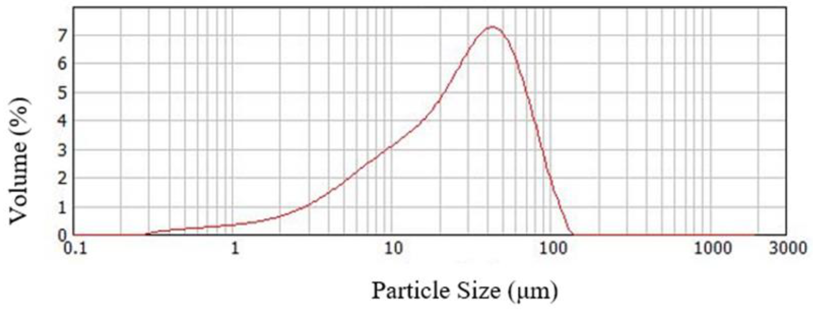
Particle size distribution after micronization to 70%—0.045 mm of the slag sample was confirmed by the laser light scattering method using Mastersizer Scirocco 2000 analyzer (Malvern Instruments, Malvern, UK) [38].
-
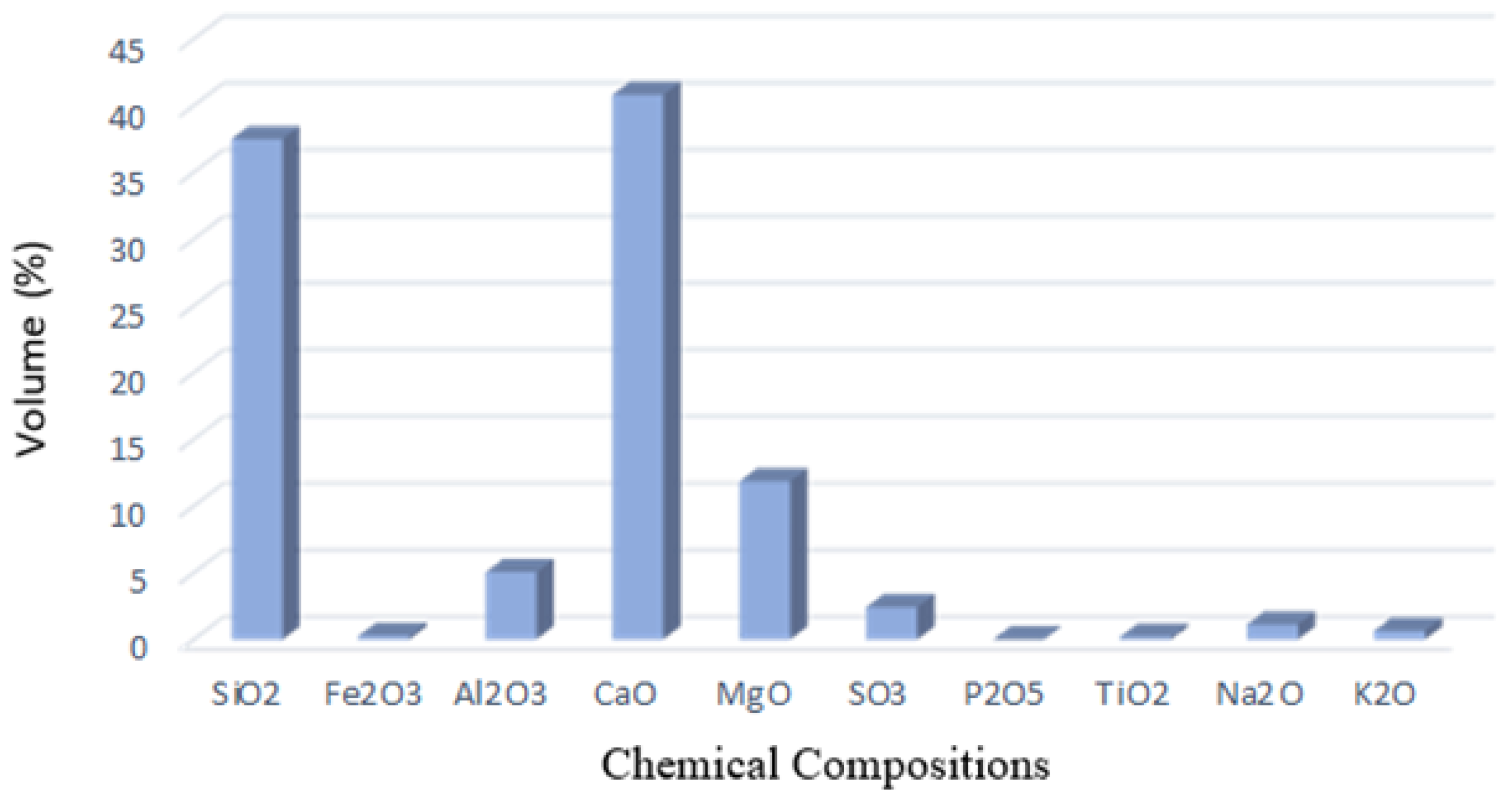
The chemical composition of the samples was presented through silicate analysis using the ICP-OES technique on a Varian 710-ES axial ICP-OES spectrometer (Varian, Houten, The Netherlands) [39].
-
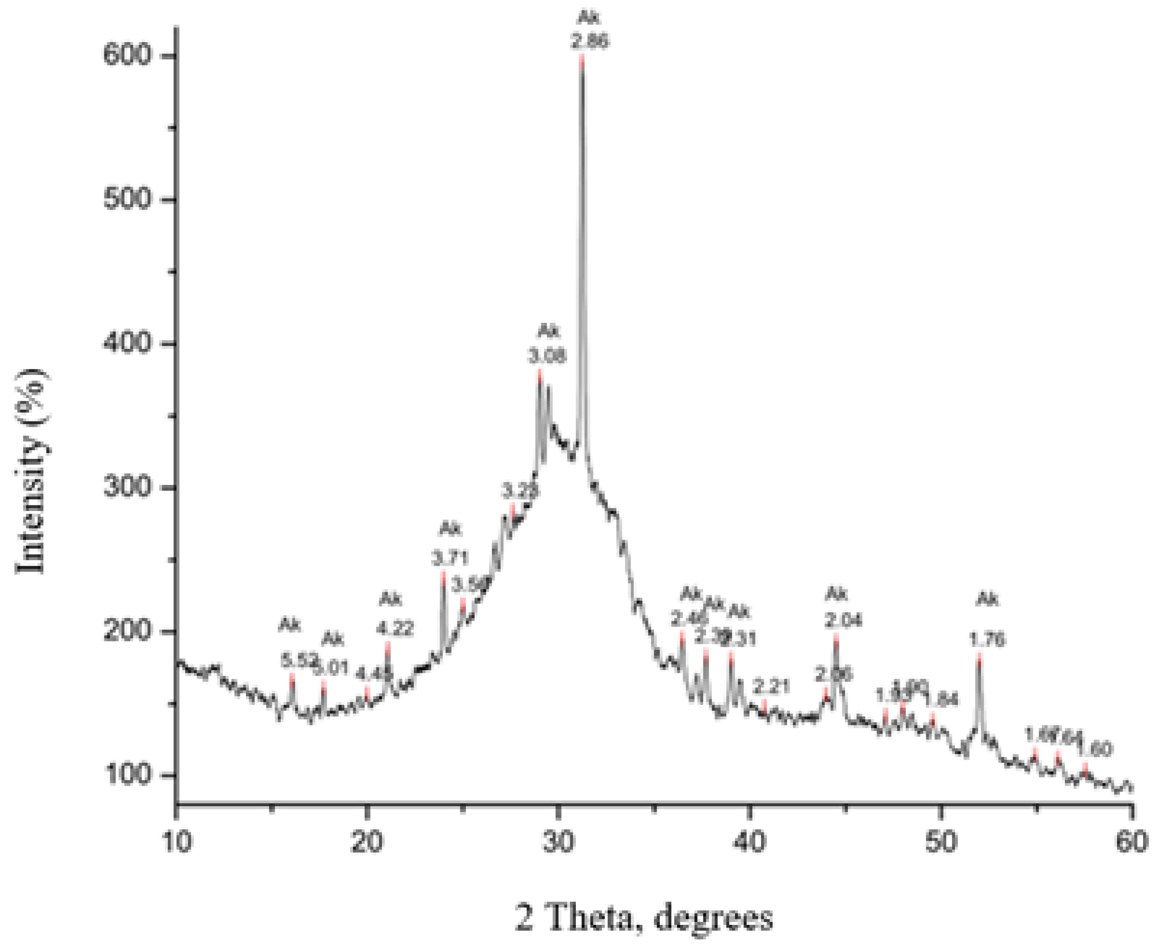
XRD analysis of the pulverized slag sample was performed on a PHILIPS PW 1710 diffractometer (Malvern Instruments, Malvern, UK) under the following conditions: copper anticathode radiation with a wavelength of CuKa = 1.5 4178 Å, graphite monochromator tube operating voltage: U = 40 kV, current strength: I = 30 mA, test range: 10–60° 2Q, step/time (qualitative tests): 0.02°/2 s [40].
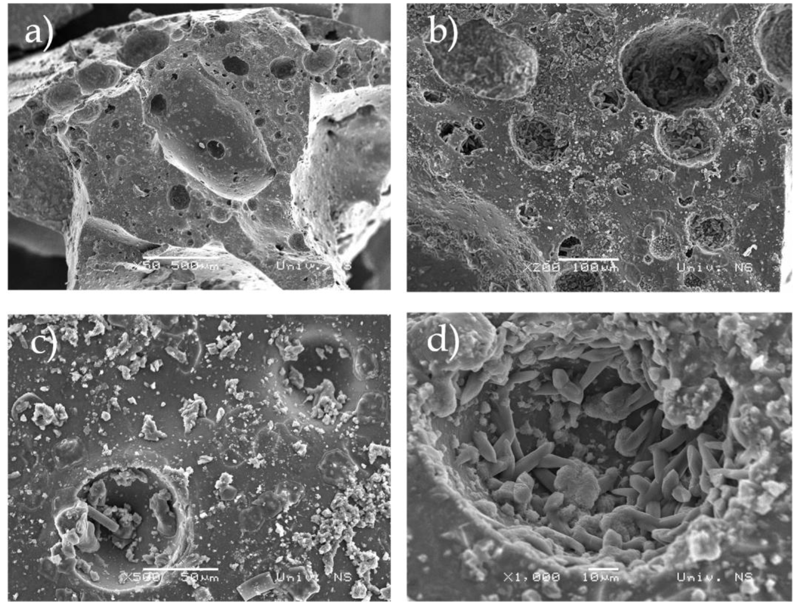
SEM analysis confirmed the mineral composition of the slag sample. The equipment comprised:
-
JEOL JSM 6460 LV, Tokyo, Japan, scanning microscope with EDS device Oxford INCA—digitized device, 3-of 4-nanometer resolution, magnification range 8–300,000×, and the possibility of working in a low vacuum to environment levels,
-
BAL-TEC, SCD 005 SPUTTER COATER, Tokyo, Japan—vacuum device for preparing samples by vaporization with gold and carbon [41].

2.2. Characterization of the Cement Sample

CEM I is a commercial product, therefore, no detailed characterization of the sample was performed except for the chemical, setting time, compressive, and flexural strength analyses.
-
The chemical analysis methodology is described in the previous chapter.
-
The cement mortars setting time was tested using a Vicat apparatus according to the SRPS EN 196-3:2017. The test room temperature should be 20 ± 2 °C and the relative humidity should be at least 50% [42].
-
Determination of flexural and compressive strength was described in SRPS EN 196-1:2017 [43].

2.3. Characterization of Danube River Water

Water from the Danube river was tested using an ion chromatography method. Ion chromatography is a method of chromatographic separation of ions in a solution using a solid ion exchange material-filled column and it is ideal for determining very low concentrations of present ions. It is possible to simultaneously analyze a group of inorganic anions (fluorides, chlorides, nitrites, bromides, nitrates, phosphates, and sulfates) and cations of alkaline and alkaline earth metals in water, as well as ammonium ions. This method is used for analyzing all types of water, and it is most widely applied in drinking water analyses [44].

2.4. Preparation and Bio-Stimulated Healing Mortar

Initial sample characterization was followed by the preparation of a new type of mortar and its characterization by examining the strengths, chemical composition, and setting time.
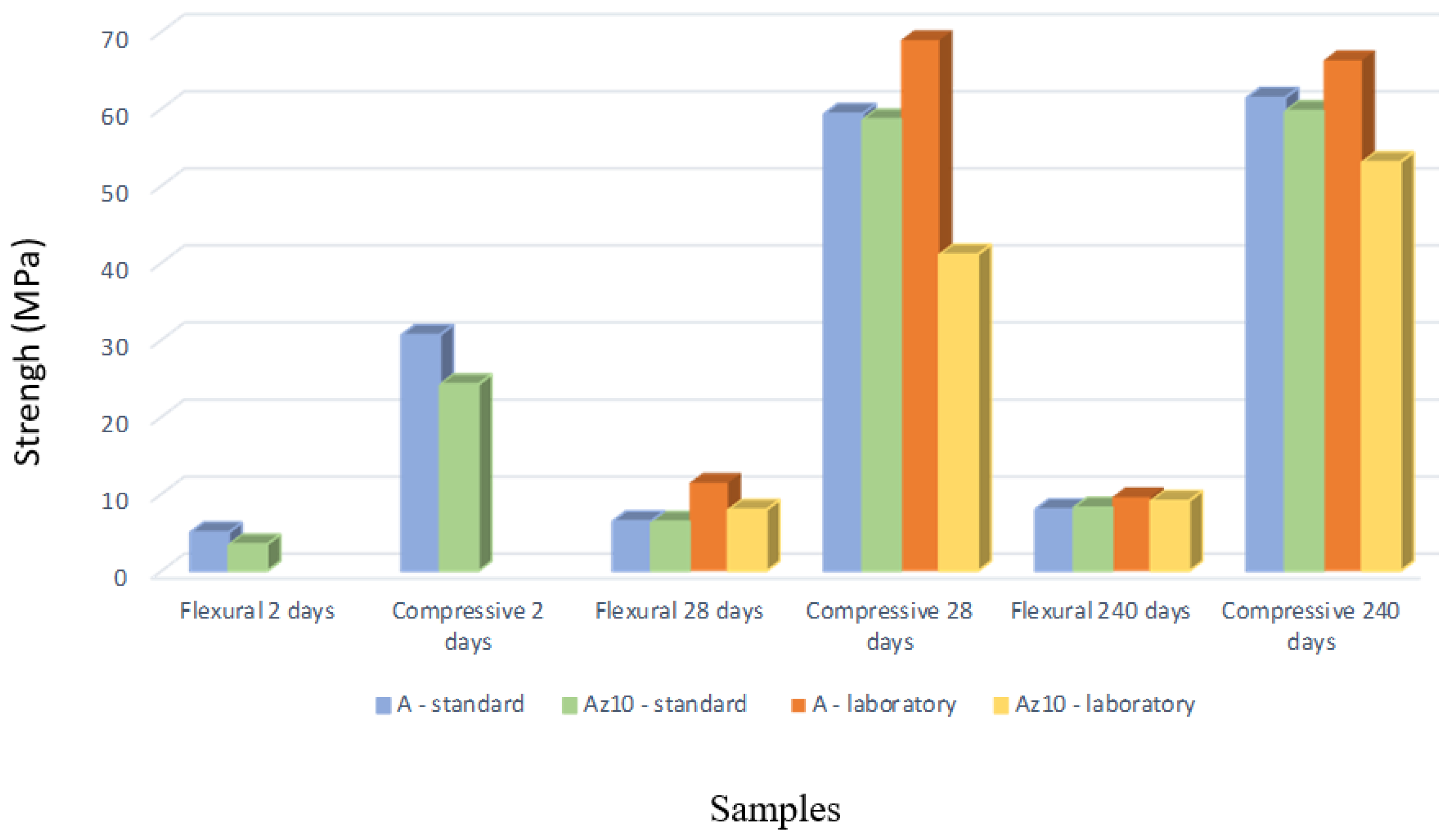
The new mortar system was prepared with a 10% slag replacement instead of alite cement using the method described in SRPS EN 196-1:2017. The sample prisms were of standard dimensions 40 × 40 × 160 mm and laboratory dimensions of 10 × 10 × 60 mm. Flexural and compressive strengths were tested after 2, 28, and 240 days of water curing on hydraulic presses by Tinius Olsen, Sari, England, a working force of up to 231 kN and VEB Thuringer Industriewerk Rauenstein, Weimar, Germany (standard prisms), as well as a working force of 0–5 kN and 25–50 kN (laboratory prisms). For this type of mortar, the setting time was also determined using a Vicat apparatus according to SRPS EN 196-3:2017. The mortar system composition is provided in Table 1.
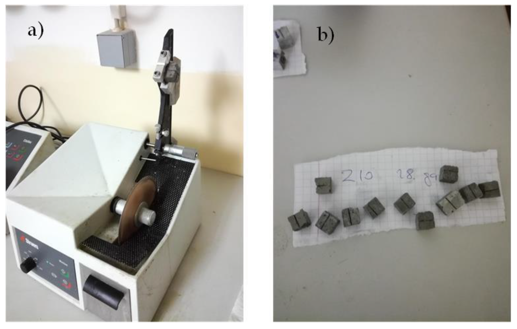
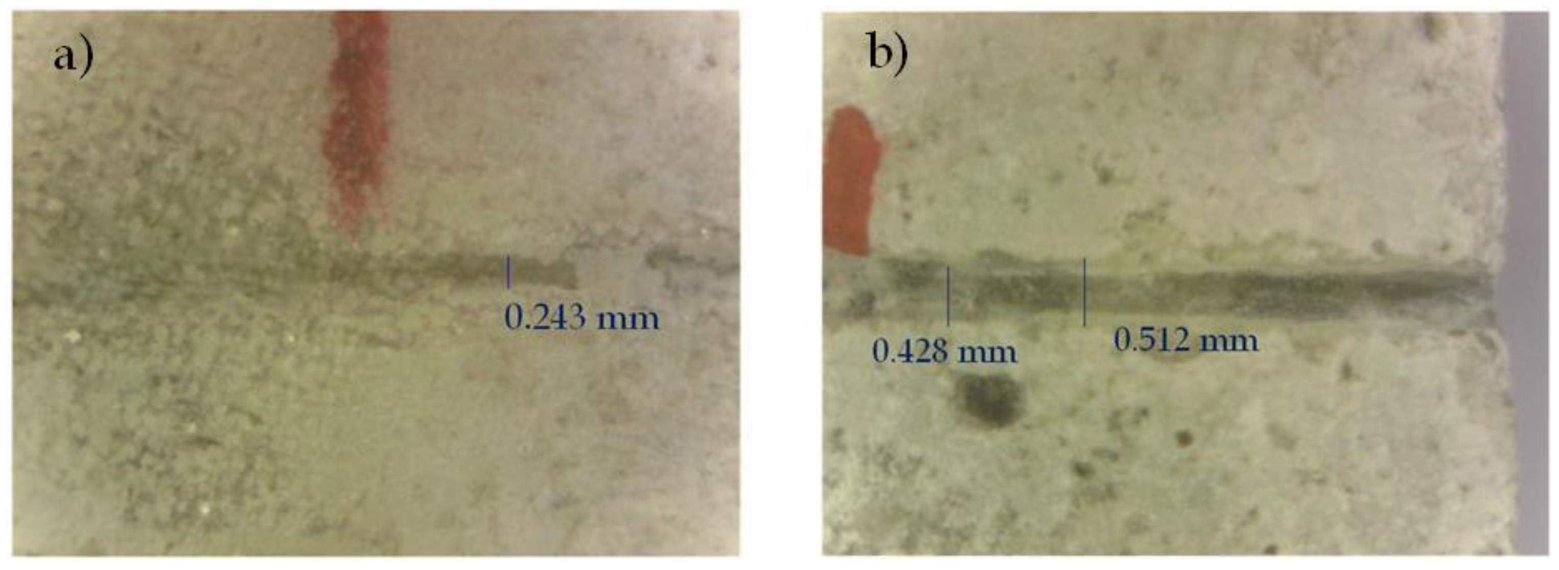
Determination of the strengths, setting time, and chemical composition of the new mortar type was followed by the preparation of laboratory sample prisms for the bacterial bio-stimulated healing experiment. After preparation and water curing for 28 days, sample prisms of laboratory dimensions were cut with a diamond knife (Figure 1a)) to 10 × 10 mm for easier manipulation, and a groove was artificially made on each sample as a real crack simulation (Figure 1b)). In this way, enough samples were prepared for the needs of further experiments.
For the bio-stimulated healing process, the S. pasteurii DSM 33 strain was selected, which is characterized by a high capacity of continuous production of carbonate and bicarbonate ions through ureolysis [11,45]. Considering that the selected bacterial strain S. pasteurii DSM 33 is highly sensitive to environmental conditions [45], the pH value had to be reduced to a value below 10, which was achieved by alternating immersion in distilled water and drying in a dryer for 2 h each. After 20 washing cycles, the pH value was lowered from 14 to 9.
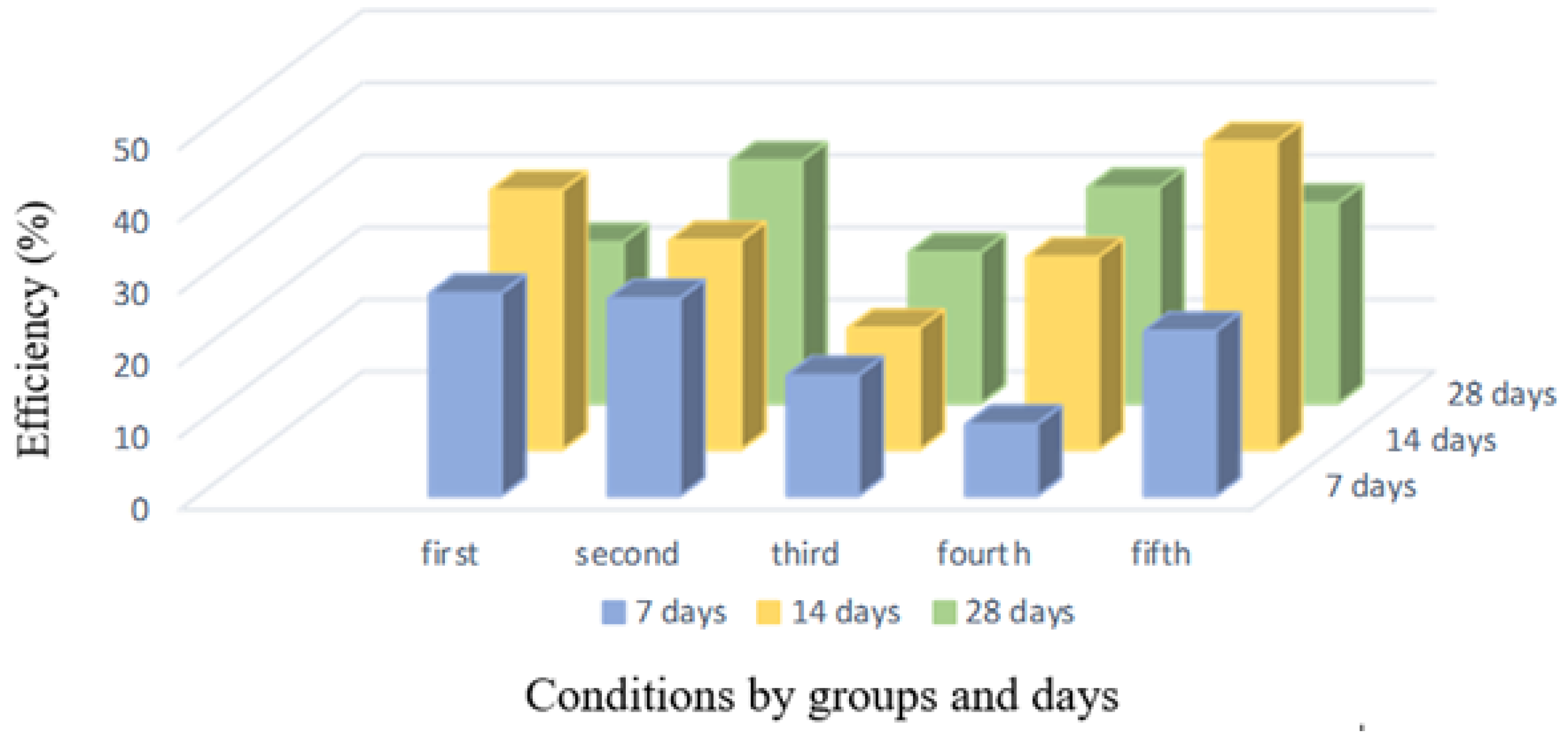
According to the established experiment program, 45 samples were singled out. The system was divided into five groups that were treated under different conditions, as shown in Table 2. Conditions 2 to 4 are those in control.
The samples were placed in Petri dishes so that the crack was on the upper side of the sample for easier healing agent application, with three repetitions in each group. Petri dishes with samples were sterilized for 1 h at 160 °C to eliminate any possibility of contamination. After sterilization, bacteria were applied in a laboratory at a constant temperature of 25 °C, which favors bacterial growth.
The bacterial suspension was freshly prepared with sterile demineralized water. The nutrient medium was also freshly prepared from urea, NaHCO3, NH4Cl, and sterile demineralized water.
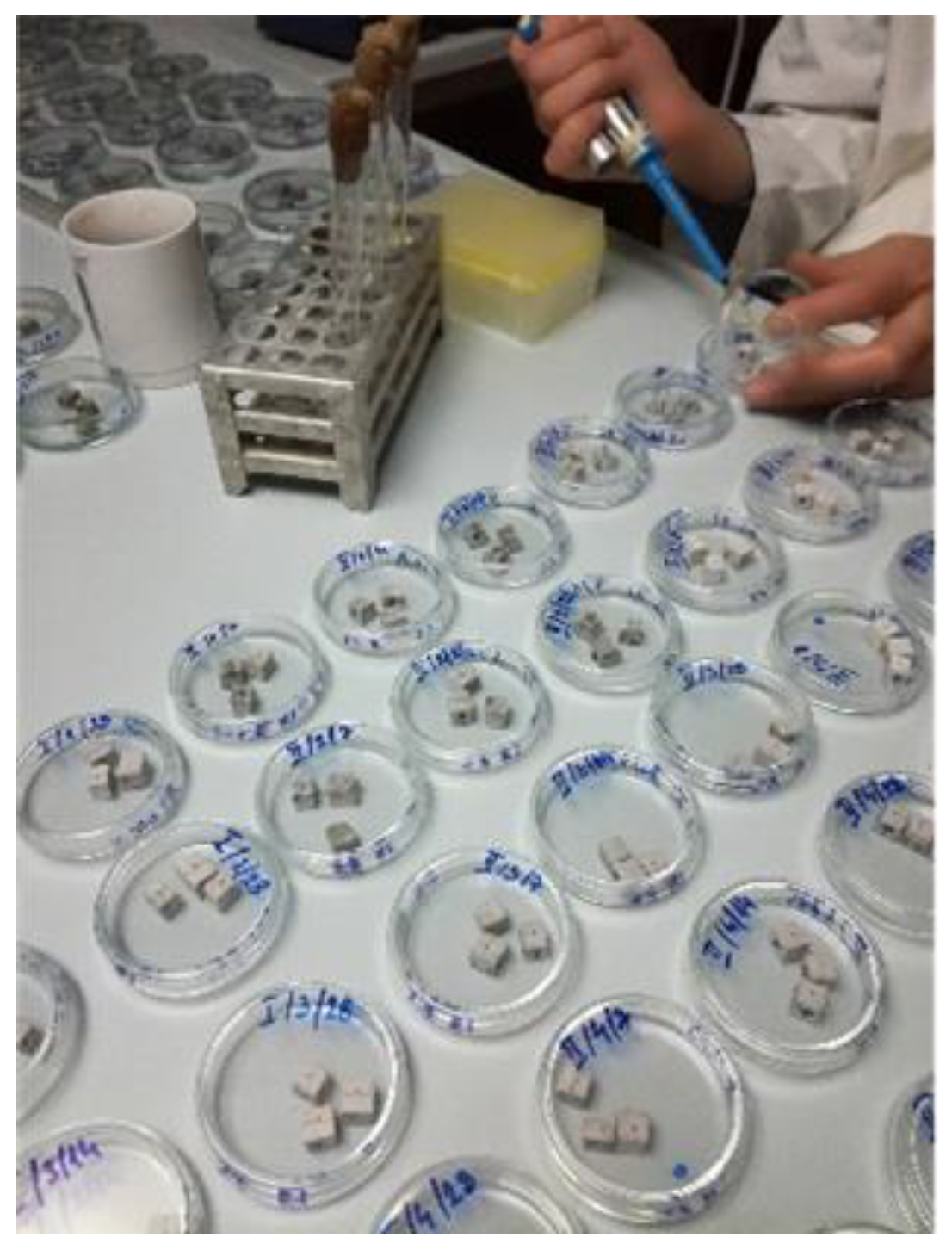
The nutrient medium and bacterial suspension were applied using a sterile pipette in the crack mid-line. Each sample of the first, second, and fifth groups was first given 50 μL of nutrient medium. After absorbing the nutrient medium, 50 μL of bacterial suspension was applied to each sample of the first and fifth groups (
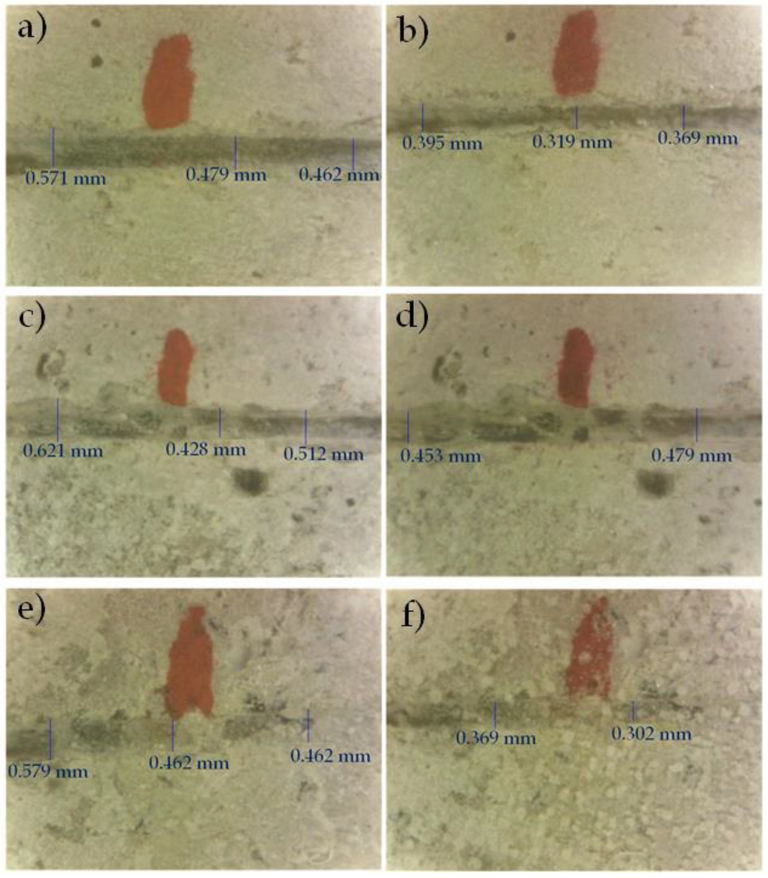
Figure 2). Finally, the sterile demineralized water was added with a sterile pipette for up to 1/3 of the sample height in the first, second, and third groups, while the fresh Danube river water was added also for up to 1/3 of the sample height in the fourth and fifth group (10 mL for smaller 6 cm diameter Petri dishes and 15 mL for larger 10 cm diameter Petri dishes). This amount of water was optimal for maintaining system humidity. After setting up the system, the Petri dishes with the samples were transferred to the Binder Climate Chamber KBWF 240, Tuttlingen, Germany. In the climate chamber, the systems were kept under controlled conditions of a temperature of 30 °C and humidity of 70% until testing.
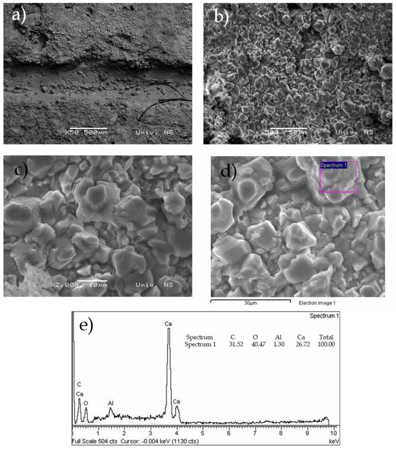
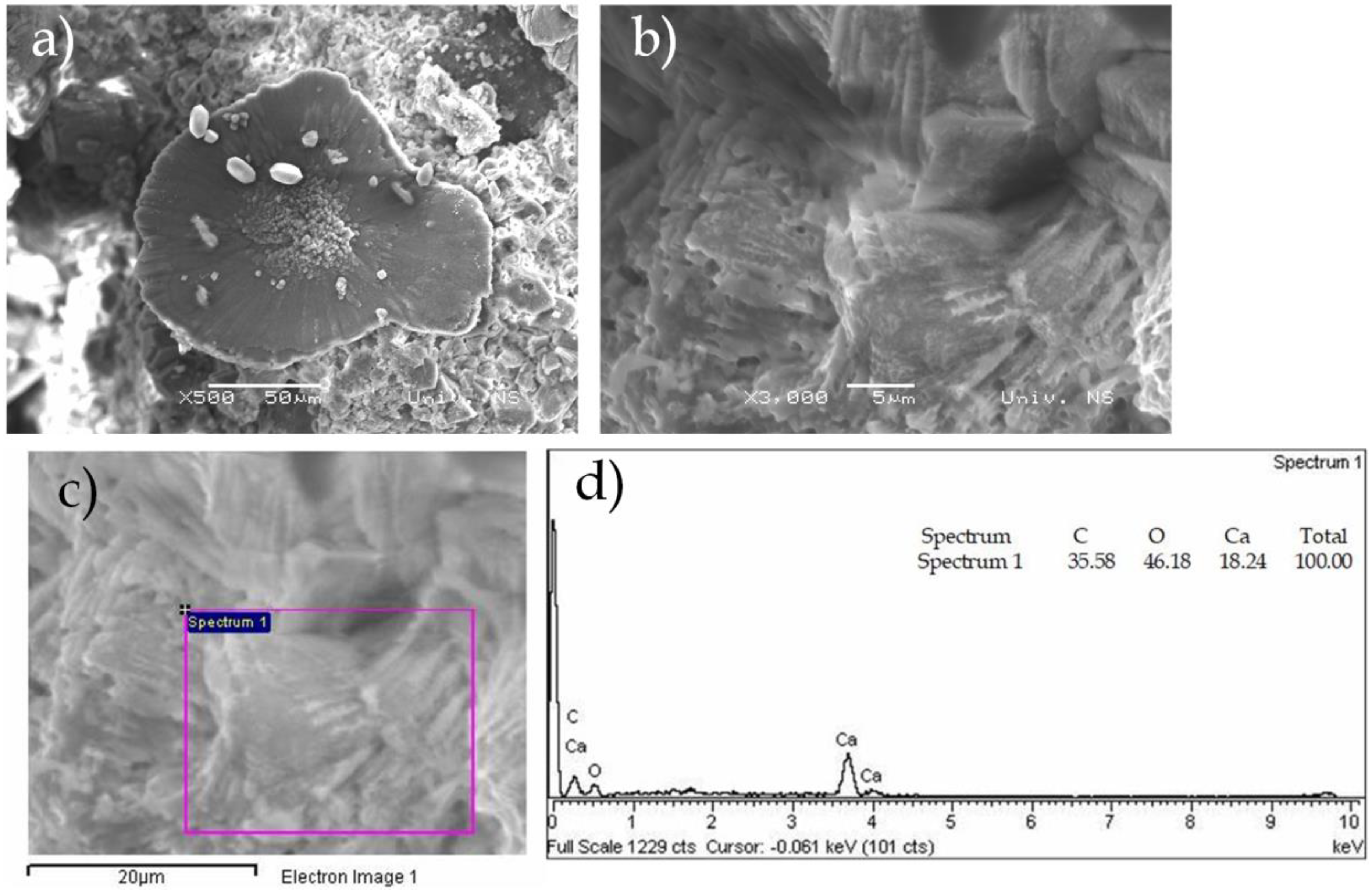
The tests’ durations were 7, 14, and 28 days after the experiments’ setup. Non-destructive methods were selected to monitor changes in the bio-stimulated healing process, portable microscope imaging (described below—Section 2.5), and SEM analysis, as already described in Section 2.1.

2.5. Identification of Cracks

Cracks were identified and non-destructively recorded using a portable Vitiny PRO10-3 microscope, Greenville, South Carolina Greenville, South Carolina, USA, which can operate at 10 to 30× magnifications. The crack width was measured with the existing integrated microscope software.

2.6. Image Classification

Image classification was performed in the MATLAB 2023A programming language using the Convolutional Neural Networks methodology—ResNet 50, which has already been pretrained to extract features from digital images based on the RGB model.

2.6.1. Basic Characteristics of the Convolutional Neural Networks (CNN) Model

Convolutional Neural Networks are an extended model of multi-layer artificial neural networks, which are developed by the addition of a new type of layer. They are predominantly used for image analysis (recognition and classification) [46].
Convolutional Neural Networks mimic the human visual system and may recognize complicated image features gradually. In the first layers of this network, simple attributes such as edges are detected. Based on what was detected in the previous, contours are recognized in the next layer. Contour detection is followed by the recognition of specific parts of the object so that the object can be classified in the final layer [47].
The principle behind Convolutional Neural Networks is reflected in the direct input of image data in raw pixels, for example, as a width of 32, height of 32, and depth of 3. The first task of a convolutional neural network model is to transform the image it receives into a computer-understandable format. More precisely, the input data is represented as a two-dimensional pixel intensity matrix in the case of a single-channel image or as a multi-dimensional matrix in the case of a multi-channel image. As a whole, in the input layer, the image data is entered into the network, and each entered pixel represents an input characteristic. Each pixel is described by its color as a color imaging system [48,49].
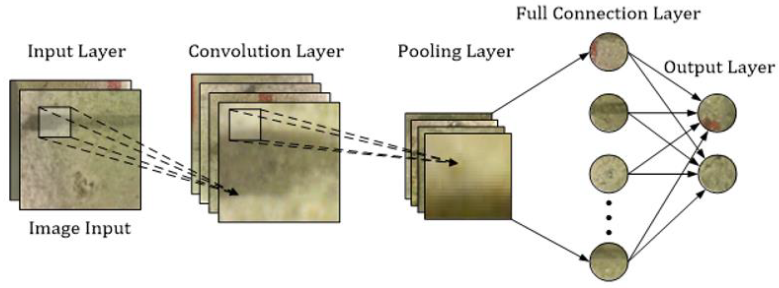
Data entry is followed by several alternating convolutional layers and pooling layers, for which alternation reduces their dimensions. The end result is images that are very small in size, each representing one matrix. The matrix values are arranged into a vector that represents the input to the fully connected network [46,47,50,51]. A schematic representation of the basic convolutional neural network on the example of a cement prism crack image from this research is shown in Figure 3.

2.6.2. Convolutional Layer

The convolutional layer serves to extract the features of the input data using the filters located inside the convolutional layer [50].
The filter window moving starts from the upper left corner of the image and goes to the right by the same value. When we reach the edge, we move it downward, repeating the process. The size of the subsample depends on the size of the filter. In this study, the output volume is obtained based on several filters that make up this layer and are grouped along the axis [50,51,53,54].

2.6.3. ReLu Layer

The ReLu layer is introduced after the convolutional layer as an additional layer to increase image non-linearity and reduce the calculation time. This layer serves to break the linearity imposed by passing the image through the convolutional layer [50,51].

2.6.4. Pooling Layer

The convolutional layer is followed by the pooling layer, in which the data dimension is reduced. This layer also has filters, but they have no weight here, unlike in the convolutional layer. Here, the role of the filter is to select the pixel that is within the dimensions covered by this layer in a given way. The maximum is often used as it works better in practice, although average values are also acceptable. The pooling layer reduces the dimension of the feature maps while retaining the most important sample information. After pooling, the image feature map is aligned in one column, resulting in a vector. The long vector obtained in this way serves as the input to the artificial neural network, which is also the final step [36,53].
In this study, both (max and average) methodologies are used as the pooling functions. The microscopic images from this experimental research showing bacterial healing in sterile demineralized water and Danube river water are visually very similar and can be classified into the same data set (Class 1). For the second data set (Class 2), images from mortar samples with sterile demineralized water without nutrient and bacterial culture were selected.
Considering that these are laboratory experiments, 51 images for each class were selected for the initial data set. This data set was augmented by rotating the images by 180°. Validation was performed on a completely new dataset consisting of 18 images for each class.
Validation success can also be shown computationally through a precision expression adapted from [55]:
precision = TP TP + FP
recall = TP TP + FN
F 1 score = 2 × recall × precision recall + precision
accuracy = TP + TN TP + TN + FN + FP
where:
  • TP—True Positive
  • FP—False Positive
  • TN—True Negative
  • FN—False Negative
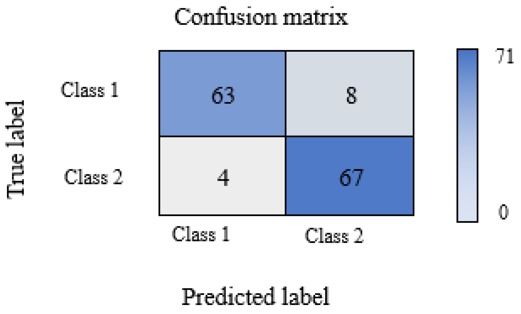
F1-score and accuracy are used to precisely assess model performance, where F1-score takes into account precision and recall and it is calculated for both classes while accuracy represents the proportion of correct recognition of the entire sample.

3. Results and Discussion

3.1. Physical–Chemical Characteristics of Slag

Based on the control check of particle size distribution by the microsizer it was found that slag sample after crushing contains 72.15% of the −0.045 mm size class which corresponds to the standard requirements and can be used for mortar preparation. The results are shown in Figure 4.
The chemical composition is provided in Figure 5.
The slag sample is dominated by the contents of SiO2 and CaO, which affects their chemical activity and volume constancy. The alkali content is low, which is advantageous as their presence is undesirable in cement production. The share of MgO in the slag is increased compared to the allowed 5%. A higher quantity of MgO can affect in addition to volume instability, the appearance of cracks [56] in mixtures with cement, which demands special attention in experimental work. The measured slag pH value is 8.
In addition to the high quantities of non-crystallized material, a smaller amount of akermanite (Ak) mineral was identified. The powder diffractogram is shown in Figure 6.
SEM microphotographs of the initial slag sample are shown in Figure 7. A typical slag appearance can be explained by a porous structure with open pores, on the surfaces of which certain crystals can be observed, which, according to the available literature, can be classified as akermanites [57,58].
Based on the detailed sample characterization and the obtained results, it was concluded that the tested slag sample can be used as an additive for cement mortars after micronization.

3.2. Physical–Chemical Characteristics of Mortar

A new type of cement was prepared with the addition of slag in an amount of 10%. After the preparation and curing, with and without slag, in a period of 2, 28, and 240 days, the mortar samples were tested for flexural and compression strength. In addition, the setting time of both cement mixtures was determined and their chemical composition was analyzed. The results of the geomechanical tests of standard and laboratory sample prisms of the new mortar system are provided in Table 3 and Figure 8.
The standard does not prescribe flexural strength values but they are always provided in reports, while compressive strength values are an important parameter that is tested and defined by the standard or based on the Rulebook on Cement Quality [59]. The compressive strength decreases with the addition of slag, but in both systems, the strength increases with the hydration time. By comparing the values obtained for standard and laboratory prisms, it can be concluded that the compressive strength results for standard prisms fully follow the compressive strength values for the laboratory prisms. Thus, the results are comparable. This conclusion is a good indicator that the following experiments can fully rely on laboratory samples and raw materials saving.
The setting time is shown in Table 4.
The new slag mortar system has a total setting time of 108 min, which is shorter than the setting time of CEM I (alite) mortar, which is 126 min, although it takes longer for the setting to start.
The chemical composition of the alite and the new mortar system is shown through silicate analysis provided in Table 5.
The chemical composition of the alite and the new mortar system (Az10) is shown based on the silicate analysis provided in Table 5. The results of the silicate analysis show that the annealing loss in both systems is below the value prescribed by the Rulebook [60]. The sulfate content (as SO3) is below the limit value for both types of cement, so there is no possibility of subsequent sulfate corrosion. The content of CaO is much higher in the slag system, which originates from the slag itself in which it is present with 40.82% and can negatively affect the volume stability of this cement system. The total alkali content expressed as Na2O + K2O is rather high, but these values do not exceed the limit (<1.5). The presence of alkali in the cement can lead to a later reaction with the aggregate in the concrete, causing a decrease in the structure’s strength [60].

3.3. Chemical Characteristics of Danube River Water

Danube river water used in the experiments was tested for pH, total nitrogen, total phosphorus, total organic carbon, ammonia, nitrates, nitrites, chlorides, COD (Chemical Oxygen Demand), BOD5 (Biochemical Oxygen Demand), sulfates, phosphates, dissolved oxygen, fluorides, hexavalent chromium, calcium, magnesium, manganese, lead, zinc, total chromium, cadmium, copper, mercury, arsenic, and iron (Table 6) [61].
The analysis determined the presence of all tested parameters in values below the maximum allowed, i.e., reference values, so that no negative influence of water was expected in further experiments of the bacterial healing process.

3.4. Bio-Stimulated Healing of Cracks

After setting up the bacterial experiments, the changes in the cracks were monitored with a portable microscope after 7, 14, and 28 days (Figure 9 shows the changes after 7 days under three characteristic conditions). All mean values of the change in cracks provided in Figure 9 are also shown tabularly (Table 7) and graphically (Figure 10).
Although according to the literature data bacteria reach their precipitation maximum after 7 days [45], when they can create a sufficient amount of calcium carbonate to close a 0.5–0.8 mm wide crack [13], the most favorable healing values were recorded with the new slag mortar system after 14 days in both waters, with efficiency being 32.02% and 42.74% for sterile demineralized and Danube river water, respectively.
Bio-stimulated healing rates after 7 and 28 days ranged between 22.39% and 28.12%, respectively. Healing was also recorded under bacteria-free conditions, namely, in sterile demineralized water at 20.99% and in Danube river water at 29.99% with initial cracks of about 0.5 mm, which can be explained by the process of autogenous healing due to unreacted mortar and slag grains [13,15].
Figure 11a,b shows SEM images of the sample with bacteria in sterile demineralized water at 1000× magnifications and the characteristic morphology of calcite crystals that started the process of bio-stimulated healing in the cracks as the result of bacterial precipitation. The appearance of the crystals is confirmed by previous studies [62]. The EDS spectrum in Figure 11c,d confirms the presence of calcium, oxygen, and carbon, which once again indicates that it is calcium carbonate. Previously published studies show that the main healing product is also calcium carbonate [17], which was confirmed in this research.
SEM images of the sample (Figure 12a) in the sterile demineralized water without nutrient and bacterial culture show that the crack has not self-healed and the crystals at 500× and 2000× magnifications (Figure 12b,c) are characteristic of slag mortars and are in line with previously published studies [63].
The SEM images and EDS of the sample treated with bacteria in Danube river water (Figure 13) also confirmed the precipitation of calcium carbonate as the main compound that fills the cracks and leads to the healing process. Calcium carbonate crystals are larger with clear rosettes, unlike crystals formed in sterile demineralized water where the crystals are smaller and more uniform.

3.5. The success of Crack Image Classification Using CNN

ResNet50 program package within Matlab2023A was used to classify images of cracks in the new slag mortar system after a period of bacterial treatment in sterile demineralized and Danube river water.
The microscopic images showing bacterial healing in sterile demineralized water and Danube river water are visually very similar and can be classified into the same data set (Class 1). For the second data set (Class 2), images from mortar samples with sterile demineralized water without nutrient and bacterial culture were selected.
Each class had 102 input images. After entering the input data into the network, the program extracts one image from each class, as shown in Figure 14. Images in Figure 14 contain data about measurements. The input image dataset of the model was without them.
The CNN had 177 nodes with 192 connections classified into input, convolutional, pooling, fully connected, ReLu, and output layers. For network training and the test, the program selected 62 (30%) and 142 (70%) input images, respectively. The first confusion matrix with the number of images obtained by the test was
59            12
11            60
After reprocessing the data through the network, a generated matrix was obtained, shown with accuracy in relation to the number of images from the test (Figure 15):
The final classification accuracy using this deep learning model was 91.55%.
To validate the classification results, a new data set with 18 images for each class was selected. After validation, a deviation was obtained in the class with bacteria for one input image (5.5%), while in the class without bacteria the deviation for two input images was (11%).
Validation success was also obtained from Equations (1) to (4) and the results are provided in Table 8.
The characteristics obtained in this way confirmed the obtained validation values and amount at 91.55%.
Based on the obtained CNN network data, it can be concluded that the model is suitable for the classification of images of changes in mortar sample cracks.

4. Conclusions and Outlook

The conclusion of these complex studies is that up to 10% of blast furnace slag can be successfully added to mortars without jeopardizing the geomechanical and chemical properties of the mortar. Further research on the bio-stimulated healing process confirmed that this quantity of slag is optimal as in combination with bacteria, it promotes autogenous healing. For the bio-stimulated healing process, the S. pasteurii DSM 33 strain was selected, which is characterized by a high capacity for continuous production of carbonate and bicarbonate ions through ureolysis. Although the bacteria reach their precipitation maximum after 7 days, current research has proven that in controlled conditions of humidity and temperature, greater healing efficiency can be achieved with a longer aging time (14 and 28 days). According to the knowledge of the authors of this work, such research for the first time included Danube river water which, based on SEM images, has a favorable effect on the formation of calcium carbonate crystals, making healing efficiency about 10% higher compared to the conditions of bacteria in sterile demineralized water. The beginning of autogenous healing was recorded in control conditions, mortar samples in demineralized water without bacteria and nutrients. Here, the efficiency ranged from 16.75% to 20.99%. Considering the success of the experiments and the multitude of recorded microscopic changes, images were also classified by Convolutional Neural Networks. Convolutional Neural Networks are widely used in practice for the classification of various types of images but according to the available literature, such an approach is not recorded for images of crack bio-stimulated healing in new types of mortar. As a result of the classification, a high percentage of accuracy of 91.55% was obtained, while during the validation, the deviation was as low as 5.5% in the class with bacteria and 11% in the class without bacteria.
Modeling and simulation of the phenomena underlying bio-stimulated healing mortar may provide a complementary tool for the experimental efforts, and our future research will be based on the following issues:
-
A larger set of input data.
-
Application of other neural networks such as VGG, AlexNet, GoogLeNet, and ZF Net.
-
Application of other machine learning classification technics such as Decision Trees, Random Forests, Support Vector Machine, Naïve Bayes, etc.
-
Input dataset obtained at other conditions (different types of cement, potable water, and similar).
-
Extension of research to macro cracks.

Author Contributions

Conceptualization, J.N., J.R., M.T. and S.V.; Methodology, J.N., J.R. and S.V.; Formal analysis and investigation, J.N., I.J., S.M. and S.V.; Sampling, dating and analysis J.N. and I.J. Writing—original draft J.N., J.R., M.T., I.J. and S.V. All authors have read and agreed to the published version of the manuscript.

Funding

The authors would like to acknowledge the support from Ministry of Science, Technological Development, and Innovations (Serbia), project No. 451-03-47/2023-01/200134, No. 451-03-47/2023-01/200131, and No. 451-03-47/2023-01/200035.

Data Availability Statement

The data presented in this study are available on request from the corresponding author.

Acknowledgments

The authors are particularly grateful to Laboratory for materials in cultural heritage (Faculty of Technology Novi Sad), Laboratory of Crystallography (Faculty of Mining and Geology Belgrade), University Center for Electron Microscopy in Novi Sad (University of Novi Sad), Mining institute Belgrade, Thermal Power Plant Kostolac B, Ministry of Education, Science and Technological Development of the Republic of Serbia.

Conflicts of Interest

The authors declare no conflict of interest.

References

  1. Mahmod, A.K.; Al-Jabbar, L.A.; Salman, M.M. Bacteria Based Self-Healing Concrete: A Review, 2nd Online Scientific Conference for Graduate Engineering Students. J. Eng. Sustain. Dev. 2021, 3-43–3-56. [Google Scholar] [CrossRef]
  2. Suleiman, A.R.; Zhang, L.V.; Nehdi, M.L. Quantifying Crack Self-Healing in Concrete with Superabsorbent Polymers under Varying Temperature and Relative Humidity. Sustainability 2021, 13, 13999. [Google Scholar] [CrossRef]
  3. Termkhajornkit, P.; Nawa, T.; Yamashiro, Y.; Saito, T. Self-healing ability of fly ash–cement systems. Cem. Concr. Compos. 2009, 31, 195–203. [Google Scholar] [CrossRef]
  4. Van Breugel, K. Is there a market for self-healing cement-based materials. In Proceedings of the First International Conference on Self Healing Materials, Noordwijk aan Zee, The Netherlands, 18–20 April 2007; pp. 1–9. [Google Scholar]
  5. Van Tittelboom, K.; De Belie, N. Self-Healing in Cementitious Materials—A Review. Materials 2013, 6, 2182–2217. [Google Scholar] [CrossRef] [PubMed] [Green Version]
  6. Mors, R.M.; Jonkers, H.M. Bacteria-Based Self-Healing Concrete—Introduction. In Proceedings of the 2nd International Conference on Microstructural-Related Durability of Cementitious Composites, Amsterdam, The Netherlands, 11–13 April 2012; pp. 1–7. [Google Scholar]
  7. Mauludin, L.F.; Oucif, C. Modeling of Self-Healing Concrete: A Review. J. Appl. Comput. Mech. 2019, 5, 526–539. [Google Scholar]
  8. Zhuang, X.; Zhou, S. The Prediction of Self-Healing Capacity of Bacteria-Based Concrete Using Machine Learning Approaches. CMC 2019, 59, 57–77. [Google Scholar] [CrossRef] [Green Version]
  9. Huang, X.; Sresakoolchai, J.; Qin, X.; Fan Ho, Y.; Kaewunruen, S. Self-Healing Performance Assessment of Bacterial-Based Concrete Using Machine Learning Approaches. Materials 2022, 15, 4436. [Google Scholar] [CrossRef]
  10. Zhutovsky, S.; Nayman, S. Modeling of crack-healing by hydration products of residual cement in concrete. Constr. Build. Mater. 2022, 340, 127682. [Google Scholar] [CrossRef]
  11. Van der Bergh, J.M.; Miljević, B.; Šovljanski, O.; Vučetić, S.; Markov, S.; Ranogajec, J.; Bras, A. Preliminary approach to bio-based surface healing of structural repair cement mortars. Constr. Build. Mater. 2020, 248, 118557. [Google Scholar] [CrossRef]
  12. Roy, R. Bacteria-Based Self-Healing Mortar with Bio-Plastic Healing Agents; Kth Royal Institute of Technology School of Architecture and the Built Environment: Stockholm, Sweden, 2020; p. 176. [Google Scholar]
  13. Grubišić, I. Samozacjeljivanje Betona Autogenim i Autonomnim Postupkom s Naglaskom na Metodu Bakterija. Master’s Thesis, Sveučilište u Splitu, Fakultet Građevinarstva, Arhitekture i Geodezije, Split, Croatia, 2020. (In Croatian). [Google Scholar]
  14. Zhang, W.; Zheng, Q.; Ashour, A.; Han, B. Self-healing cement concrete composites for resilient infrastructures: A review. Compos. Part B 2020, 189, 107892. [Google Scholar] [CrossRef]
  15. Guzlena, S.; Sakale, G. Self-healing concrete with crystalline admixture—A review. IOP Conf. Ser. Mater. Sci. Eng. 2019, 660, 012057. [Google Scholar] [CrossRef]
  16. Van der Bergh, J.M.; Miljević, B.; Vučetić, S.; Šovljanski, O.; Markov, S.; Riley, M.; Ranogajec, J.; Bras, A. Comparison of Microbially Induced Healing Solutions for Crack Repairs of Cement-Based Infrastructure. Sustainability 2021, 13, 4287. [Google Scholar] [CrossRef]
  17. Li, G.; Liu, S.; Niu, M.; Liu, Q.; Yang, X.; Deng, M. Effect of granulated blast furnace slag on the self-healing capability of mortar incorporating crystalline admixture. Constr. Build. Mater. 2020, 239, 117818. [Google Scholar] [CrossRef]
  18. Šovljanski, O.; Tomić, A.; Markov, S. Relationship between Bacterial Contribution and Self-Healing Effect of Cement-Based Materials. Microorganisms 2022, 10, 1399. [Google Scholar] [CrossRef]
  19. Sagripanti, J.L.; Bonifacino, A. Comparative Sporicidal Effects of Liquid Chemical Agents. Appl. Environ. Microbiol. 1996, 62, 545–551. [Google Scholar] [CrossRef] [Green Version]
  20. Algaifi, H.A.; Abu Bakar, S.; Sam, A.R.M.; Abidin, A.R.Z.; Shahir, S.; AL-Towayti, W.A.H. Numerical modeling for crack self-healing concrete by microbial calcium carbonate. Constr. Build. Mater. 2018, 189, 816–824. [Google Scholar] [CrossRef]
  21. Althoey, F.; Amin, M.N.; Khan, K.; Usman, M.M.; Ali Khan, M.; Javed, M.F.; Sabri, M.M.S.; Alrowais, R.; Maglad, A.M. Machine learning based computational approach for crack width detection of self-healing concrete. Case Stud. Constr. Mater. 2022, 17, e01610. [Google Scholar] [CrossRef]
  22. Mangalathua, S.; Hwangb, S.H.; Choic, E.; Jeonb, J.S. Rapid seismic damage evaluation of bridge portfolios using machine learning techniques. Eng. Struct. 2019, 201, 109785. [Google Scholar] [CrossRef]
  23. Yuan, X.; Zhong, J.; Zhu, Y.; Chen, G.; Dagli, C. Post-earthquake regional structural damage evaluation based on artificial neural networks considering variant structural properties. Structures 2023, 52, 971–982. [Google Scholar] [CrossRef]
  24. Cosgun, C. Machine learning for the prediction of evaluation of existing reinforced concrete structures performance against earthquakes. Structures 2023, 50, 1994–2003. [Google Scholar] [CrossRef]
  25. Mirbod, M.; Shoar, M. Intelligent Concrete Surface Cracks Detection using Computer Vision, Pattern Recognition, and Artificial Neural Networks. Procedia Comput. Sci. 2023, 217, 52–61. [Google Scholar] [CrossRef]
  26. Cardellicchio, A.; Ruggieri, S.; Nettis, A.; Renò, V.; Uva, G. Physical interpretation of machine learning-based recognition of defects for the risk management of existing bridge heritage. Eng. Fail. Anal. 2023, 149, 107237. [Google Scholar] [CrossRef]
  27. Abubakr, M.; Rady, M.; Badran, K.; Mahfouz, S.Y. Application of deep learning in damage classification of reinforced concrete bridges. Ain Shams Eng. J. 2023, 102297. [Google Scholar] [CrossRef]
  28. Deng, L.; Zhang, A.; Guo, J.; Liu, Y. An Integrated Method for Road Crack Segmentation and Surface Feature Quantification under Complex Backgrounds. Remote Sens. 2023, 15, 1530. [Google Scholar] [CrossRef]
  29. Mir, B.A.; Sasaki, T.; Nakao, K.; Nagae, K.; Nakada, K.; Mitani, M.; Tsukada, T.; Osada, N.; Terabayashi, K.; Jindai, M. Machine learning-based evaluation of the damage caused by cracks on concrete structures. Precis. Eng. 2022, 76, 314–327. [Google Scholar] [CrossRef]
  30. Que, Y.; Dai, Y.; Ji, X.; Leung, A.; Chen, Z.; Tang, Y.; Jiang, Z. Automatic classification of asphalt pavement cracks using a novel integrated generative adversarial networks and improved VGG model. Eng. Struct. 2023, 277, 15406. [Google Scholar] [CrossRef]
  31. Iraniparast, M.; Ranjbar, S.; Rahai, M.; Nejad, F.M. Surface concrete cracks detection and segmentation using transfer learning and multi-resolution image processing. Structures 2023, 54, 386–398. [Google Scholar] [CrossRef]
  32. Tang, Y.; Huang, Z.; Chen, Z.; Chen, M.; Zhou, H.; Zhang, H.; Sun, J. Novel visual crack width measurement based on backbone double-scale features for improved detection automation. Eng. Struct. 2023, 274, 115158. [Google Scholar] [CrossRef]
  33. Guzm´an-Torres, J.A.; Naser, M.Z.; Domínguez-Mota, F.J. Effective medium crack classification on laboratory concrete specimens via competitive machine learning. Structures 2022, 37, 858–870. [Google Scholar] [CrossRef]
  34. Ali, L.; Alnajjar, F.; Al Jassmi, H.; Gochoo, M.; Khan, W.; Adel Serhani, M. Performance Evaluation of Deep CNN-Based Crack Detection and Localization Techniques for Concrete Structures. Sensors 2021, 21, 1688. [Google Scholar] [CrossRef]
  35. Mascarenhas, S.; Agarwal, M. A comparison between VGG16, VGG19 and ResNet50 architecture frameworks for Image Classification. In Proceedings of the 2021 International Conference on Disruptive Technologies for Multi-Disciplinary Research and Applications (CENTCON), Bengaluru, India, 19–21 November 2021; pp. 96–99. [Google Scholar] [CrossRef]
  36. Dabović, M.M.; Tartalja, I.I. Duboke konvolucijske neuronske mreže—Koncepti i aktuelna istraživanja. In Proceedings of the Zbornik 61. Konferencije za Elektroniku, Telekomunikacije, Računarstvo, Automatiku i Nuklearnu Tehniku, ETRAN 2017, Kladovo, Serbia, 5–8 June 2017; ETRAN Society: Belgrade, Serbia, 2017. VI1.1.1-6. ISBN 978-86-7466-692-0. (In Serbian). [Google Scholar]
  37. Bagga, M.; Hamley-Bennett, C.; Alex, A.; Freeman, B.L.; Justo-Reinoso, I.C.; Mihai, I.; Gebhard, S.; Paine, K.; Jefferson, A.D.; Masoero, E.; et al. Advancements in bacteria based self-healing concrete and the promise of modelling. Review. Constr. Build. Mater. 2022, 358, 129412. [Google Scholar] [CrossRef]
  38. Equipment brochure of the Department of Carbohydrate Foods of the Faculty of Technology in Novi Sad. Available online: https://www.tf.uns.ac.rs/en/departments/department-of-carbohydrate-food-engineering.html (accessed on 26 January 2019).
  39. Equipment brochure of the Mining Institute. Available online: https://ribeograd.ac.rs/en/laboratory-researchs/laboratory-of-solid-fuels/ (accessed on 19 May 2023).
  40. Equipment brochure of the Faculty of Mining and Geology in Belgrade. Available online: https://rgf.bg.ac.rs/page.php?page=centri_i_lab (accessed on 7 April 2019).
  41. Equipment brochure of the University Center for Electron Microscopy in Novi Sad (Department of Biology and Ecology, Faculty of Science). Available online: https://www.uns.ac.rs/index.php/en/science/scientific-potentials-of-uns/laboratories/faculty-of-sciences (accessed on 3 April 2023).
  42. Standard SRPS EN 196-3:2017; Metode Ispitivanja Cementa—Deo 3: Određivanje Vremena Vezivanja i Stalnosti Zapremine. Institut za Standardizaciju Srbije: Belgrade, Serbia, 2017. (In Serbian)
  43. Standard SRPS EN 196-1:2017; Metode Ispitivanja Cementa—Deo 1: Određivanje Čvrstoće. Institut za Standardizaciju Srbije: Belgrade, Serbia, 2018. (In Serbian)
  44. Žarković, D.B. Jonska Hromatografija—Razvoj Metode za Analizu i Kontrolu Kvaliteta Vode u Proizvodnji Papira. Ph.D. Thesis, Tehnološko–Metalurški Fakultet, Univerzitet u Beogradu, Belgrade, Serbia, 2011. (In Serbian). [Google Scholar]
  45. Šovljanski, O. Mikrobiološka Precipitacija Karbonata—Od Odabira Induktora do Ispitivanja Bioprocesnih Parametara. Ph.D. Thesis, Tehnološki Fakultet Novi Sad, Novi Sad, Serbia, 2021. (In Serbian). [Google Scholar]
  46. Ševo, I. Specijalizovana Neuronska Mreža za Klasifikaciju i Segmentaciju Aero-Snimaka. Ph.D. Thesis, Elektrotehnički Fakultet, Univerzitet u Banjoj Luci, Banja Luka, Bosnia and Herzegovina, 2020. (In Bosnian). [Google Scholar]
  47. Matematički Fakultet, Univerzitet u Beogradu. Neuronske Mreže i Duboko Učenje; Mašinsko Učenje 2020/21; Matematički Fakultet, Univerzitet u Beogradu: Belgrade, Serbia, 2020; Available online: http://ml.matf.bg.ac.rs/readings/slajdovi/10_NeuronskeMreze.pdf (accessed on 18 January 2023). (In Serbian)
  48. Matoš, I. Klasifikacija Prometnih Znakova Korištenjem Konvolucijskih Neuronskih Mreža. Licentiate Thesis, Fakultet Elektrotehnike, Računarstva i Informacijskih Tehnologija, Sveučilište Josipa Jurja Strossmayera u Osijeku, Osijek, Croatia, 2020. (In Croatian). [Google Scholar]
  49. Shang, K. Applying Image Recognition to Insurance; Society of Actuaries Research Expanding Boundaries Pool: Schaumburg, IL, USA, 2018. [Google Scholar]
  50. Repić, M.; Ralević, N. Primena konvolucionih neuralnih mreža kod prepoznavanja slika u osiguranju. Zb. Rad. Fak. Teh. Nauka Novi Sad 2021, 36, 1428–1431. [Google Scholar] [CrossRef]
  51. Zariea, M.; Jahedsaravania, A.; Massinaeib, M. Flotation froth image classification using convolutional neural networks. Miner. Eng. 2020, 155, 106443. [Google Scholar] [CrossRef]
  52. Tian, D.; Yamagiwa, S.; Wada, K. Heuristic Method for Minimizing Model Size of CNN by Combining Multiple Pruning Techniques. Sensors 2022, 22, 5874. [Google Scholar] [CrossRef]
  53. Nakhaei, F.; Rahimi, S.; Fathi, M. Prediction of Sulfur Removal from Iron Concentrate Using Column Flotation Froth Features: Comparison of k-Means Clustering, Regression, Backpropagation Neural Network, and Convolutional Neural Networ. Minerals 2022, 12, 1434. [Google Scholar] [CrossRef]
  54. Introduction to Neural Networks. Available online: https://hashdork.com/sr/neural-network/ (accessed on 18 January 2023).
  55. Gao, X.; Tang, Z.; Xie, Y.; Zhang, H.; Gui, W. A layered working condition perception integrating handcrafted with deep features for froth flotation. Miner. Eng. 2021, 170, 107059. [Google Scholar] [CrossRef]
  56. Bušatlić, I.; Bušatlić, N.; Merdić, N.; Haračić, N. Osnove Hemije i Tehnologije Portland Cementa; Fojnica: Zenica, Bosnia and Herzegovina, 2020; p. 385. ISBN 978-9958-17-168-0. (In Bosnian) [Google Scholar]
  57. Duana, P.; Shuia, Z.; Chena, W.; Shenb, C. Enhancing microstructure and durability of concrete from ground granulated blast furnace slag and metakaolin as cement replacement materials. J. Mater. Res. Technol. 2013, 2, 52–59. [Google Scholar] [CrossRef] [Green Version]
  58. Han, Z.; Feng, P.; Gao, C.; Shen, Y.; Shuai, C.; Peng, S. Microstructure, mechanical properties and in vitro bioactivity of akermanite scaffolds fabricated by laser sintering. Mater. Sci. 2014, 24, 2073–2080. [Google Scholar] [CrossRef]
  59. Službeni Glasnik. Pravilnik o Kvalitetu Cementa ("Sl. Glasnik RS", br. 34/2013 i 44/2014); Službeni Glasnik: Belgrade, Serbia, 2014. (In Serbian) [Google Scholar]
  60. Ilić, I. Mogućnost Primene Mikroniziranog i Klasiranog Elektrofilterskog Pepela kao Aditiva za Proizvodnju Građevinskih Materijala. Master’s Thesis, Rudarsko–Geološki Fakultet, Univerzitet u Beogradu, Belgrade, Serbia, 2009. (In Serbian). [Google Scholar]
  61. Internal archive of technical documentation of Thermal Power Plant Kostolac. Available online: https://www.eps.rs/lat/kostolac/Stranice/zastita-zivotne-sredine.aspx (accessed on 16 December 2022).
  62. Vučetić, S.; Čjepa, D.; Miljević, B.; van der Bergh, J.M.; Šovljanski, O.; Tomić, A.; Nikolić, E.; Markov, S.; Hiršenberger, H.; Ranogajec, J. Bio-Stimulated Surface Healing of Historical and Compatible Conservation Mortars. Materials 2023, 16, 642. [Google Scholar] [CrossRef]
  63. Schneider, N.; Stephan, D. Reactivation of a Retarded Suspension of Ground Granulated Blast-Furnace Slag. Materials 2016, 9, 174. [Google Scholar] [CrossRef] [Green Version]
Figure 1. Sample preparation: (a) applied laboratory equipment (diamond knife); (b) appearance of the prepared cracked sample.
Buildings 13 01751 g001
Figure 2. Setup of bio-stimulated healing process.
Buildings 13 01751 g002
Figure 3. Simplified schematic representation of a Convolutional Neural Network on the example of a crack image [adapted from [52].
Buildings 13 01751 g003
Figure 4. Particle size distribution in the slag sample graph.
Buildings 13 01751 g004
Figure 5. Chemical composition of the slag sample.
Buildings 13 01751 g005
Figure 6. Diffractogram of the slag sample.
Buildings 13 01751 g006
Figure 7. SEM image of the slag sample (a) magnification 50×, (b) magnification 200×, (c) magnification 500×, and (d) magnification 1000×.
Buildings 13 01751 g007
Figure 8. Mechanical characteristics of standard and laboratory prisms.
Buildings 13 01751 g008
Figure 9. Changes in the new mortar sample after 7 days under controlled conditions, optical microscopy: (a) first group/condition—0 days, (b) first group/condition—7 days, (c) third group/condition—0 days, (d) third group/condition—7 days, (e) fifth group/condition—0 days, and (f) fifth group/condition—7 days.
Buildings 13 01751 g009
Figure 10. Efficiency of the new mortar system by days and conditions.
Buildings 13 01751 g010
Figure 11. SEM, EDS results of the sample with bacteria in sterile demineralized water (a,b) 1000× magnification, (c,d) EDS spectrum at 1000× magnification.
Buildings 13 01751 g011
Figure 12. SEM, EDS images of the sample without bacteria in sterile demineralized water (a) 50× magnification, (b) 500× magnification, (c) 2000× magnification, (d,e) EDS spectrum at 2000× magnification.
Buildings 13 01751 g012
Figure 13. SEM, EDS results of the sample with bacteria in Danube river water (a) 500× magnification, (b) 3000× magnification, (c,d) EDS spectrum at 3000× magnification.
Buildings 13 01751 g013
Figure 14. Typical image of a sample from the class (a) with bacteria and (b) without bacteria.
Buildings 13 01751 g014
Figure 15. Generated matrix.
Buildings 13 01751 g015
Table 1. Mortar system composition.
System/CompositionCEM I, gThree-Fraction Sand, gGranulated Blast Furnace Slag, gWater, mL
Az10 *405135045225
* Legend: Az10—CEM I with the addition of 10% slag.
Table 2. Conditions for systems.
GroupsConditionsDays
1bacterial suspension, nutrient medium, sterile demineralized water7, 14, 28
2nutrient medium, sterile demineralized water7, 14, 28
3sterile demineralized water7, 14, 28
4Danube river water7, 14, 28
5bacterial suspension, nutrient medium, Danube river water7, 14, 28
Table 3. Mechanical characteristics of standard and laboratory prisms.
System/StrengthFlexural 2 Days, MPaCompressive 2 Days, MPaFlexural 28 Days, MPaCompressive 28 Days, MPaFlexural 240 Days, MPaCompressive 240 Days, MPa
A * standard530.636.4759.338.0161.42
Az10 * standard3.4424.226.3958.618.2359.71
A laboratory--11.4468.909.5866.29
Az10 laboratory--7.9441.089.1053.07
* Legend: A—CEM I, Az10—CEM I with the addition of 10 mas% slag, standard 40 × 40 × 160 mm and laboratory 10 × 10 × 60 mm.
Table 4. Alite systems setting time.
System/Setting TimeSetting to Start Time, minSetting to Finish Time, minTotal Setting Time, min
A86212126
Az10115223108
Table 5. Chemical composition of the alite and the new mortar system.
Content, %
SystemSiO2Fe2O3Al2O3CaOMgOSO3P2O5TiO2Na2OK2OAnnealing Loss
A22.101.574.4536.162.113.150.100.280.550.653.85
Az1022.801.364.6650.372.733.620.090.260.460.823.63
Table 6. Analysis of Danube river water.
parameterpHtotal nitrogentotal phosphorustotal organic carbonammonianitrates
measured value8.471.350.0471.89<0.0781.317
reference value6.5–8.52.00.25.00.33.0
parameternitritesCODBOD5sulfatesphosphatesdissolved oxygen
measured value0.0198.01.237.380.0448.86
reference value0.03155.01000.17.0
parameterfluorideshexavalent chromiumcalciummanganesemanganeselead
measured value<0.5<0.153.012.860.01<0.01
reference value-0.1--0.10.05
parameterzinctotal chromiumcadmiumcoppermercuryarseniciron
measured value<0.03<0.0060.0009<0.02<0.0003<0.010.122
reference value0.70.050.0050.0220.0010.010.5
Table 7. Mean crack width of the new mortar system with healing efficiency by conditions.
Group/Condition
HealingFirstSecondThirdFourthFifth
Initial width, mm0.5040.4660.5670.5670.569
Width after 7 days, mm0.3610.3360.4660.5080.445
Efficiency, %28.1227.3716.759.9622.88
Initial width, mm0.5420.6590.6380.4870.588
Width after 14 days, mm0.3470.4680.5290.3570.330
Efficiency, %32.0229.0416.9026.7342.74
initial width, mm0.4470.7220.5170.5710.506
Width after 28 days, mm0.3460.4830.4070.3990.357
Efficiency, %22.3933.6820.9929.9927.80
Table 8. Indicators for each class.
IndicatorsPrecisionRecallF1-scoreAccuracy
Class 10.940290.887320.913030.91549
Class 20.893330.943660.91781
Disclaimer/Publisher’s Note: The statements, opinions and data contained in all publications are solely those of the individual author(s) and contributor(s) and not of MDPI and/or the editor(s). MDPI and/or the editor(s) disclaim responsibility for any injury to people or property resulting from any ideas, methods, instructions or products referred to in the content.

