1. Introduction
The masonry infill (MI) plays a significant role under lateral loads on reinforced concrete (RC) frames. All major codes have ignored, in the past, the contribution of MI to strength and stiffness by treating it as non-structural elements [
1]. Different types of MI used worldwide. The brick masonry has been widely used in construction of high-rise buildings because of huge benefits it has when compared with other types of MI. Masonry behavior under the action of lateral loads showed poor performance because of its insufficient shear and flexure strengths. The brittle nature of masonry creates a lot of damage to the structure and life of humans under heavy lateral loads [
2].
The damage to buildings during past earthquakes reveals that unreinforced infill masonry may exhibit a poor performance under the action of lateral loads, and it also depends on several factors, such as workmanship and design factors adopted in construction. In recent studies, several researchers focused on strengthening the masonry in seismic areas to increase the strength and stiffness of the structure to resist lateral loads [
3,
4].
The strengthening of infill masonry elements may play a crucial role in avoiding in-plane and out-of-plane failure in masonry elements. Several researchers reported the merits and demerits observed under different reinforcing techniques. The use of fiber-reinforced polymer with organic (epoxy-resin-based) composites for applications in masonry structures is discouraged because of the drawbacks pertaining to diminished performance at elevated temperatures, requirements of protective coatings, degradation of mechanical properties after continuous exposure to certain environmental surroundings [
5], lack of compatibility between the resin and masonry surface, production of toxic gases associated with the use of FRP resin in epoxy application and relatively higher level of care and supervision required in application [
6,
7]. To overcome these drawbacks, environmentally friendly, thermal-resistant, non-corrosive composite material is used to reinforce walls by replacing FRPs with geo-fabric materials [
8,
9,
10], and results showed that these geo-fabrics help to increase the shear and flexural capacity [
11,
12].
The behavior of MI-RC frames under critical combinations of lateral loads is very complex. Analytical studies conducted on MI-RC frames by modelling masonry using different methods have illustrated the importance of MI in enhancing the lateral stiffness of the frame [
13]. The change in the lateral stiffness and mass will change the dynamic characteristics of the frame. Hence, to account for the composite action between the RC frame and MI, proper analytical models need to be developed to design MI-RC structures [
14,
15]. Recent studies conducted on MI-RC frames being subjected to pseudo-dynamic tests have indicated an increased structural response with respect to load-carrying capacity and stiffness when the connectivity of MI-RC frames is improved [
16,
17].
The analytical models developed to predict the structural response of infilled reinforced RC frames must consider the geometric and material non-linearity. The developed analytical models can only be validated through experimental studies. Interfacial behavior between MI and RC also plays a major role in the case of MI-RC frames. In the Indian context, there are scant studies, especially related to the interfacial strengthening of MI-RC frames subjected to in-plane lateral loads. Further, the increased strength and lateral stiffness contributed by MI influence the post-yield response significantly. These structural responses can be well understood through experimental investigations. This paper deals with the behavior of the lateral load responses of MI-RC frames with and without polyester geo-fabric reinforcements at interfaces subjected to in-plane reversed cyclic lateral loads. This experimental investigation aims to describe the influence of brick MI with and without geo-fabric on the lateral-load-carrying capacity and in-elastic behavior of the MI-RC frame.
2. Experimental Program
2.1. Test Specimens
In the present experimental investigations, three geometrically half-scaled reinforced concrete frames have been considered. The specimen indicates the following three cases:
- −
Single-bay two-story conventional MI-RC frame.
- −
Single-bay two-story MI-RC frame with geo-fabric reinforcements at interfaces.
- −
Single-bay two-story MI-RC frame with geo-fabric reinforcements at interfaces with an open ground (soft) story.
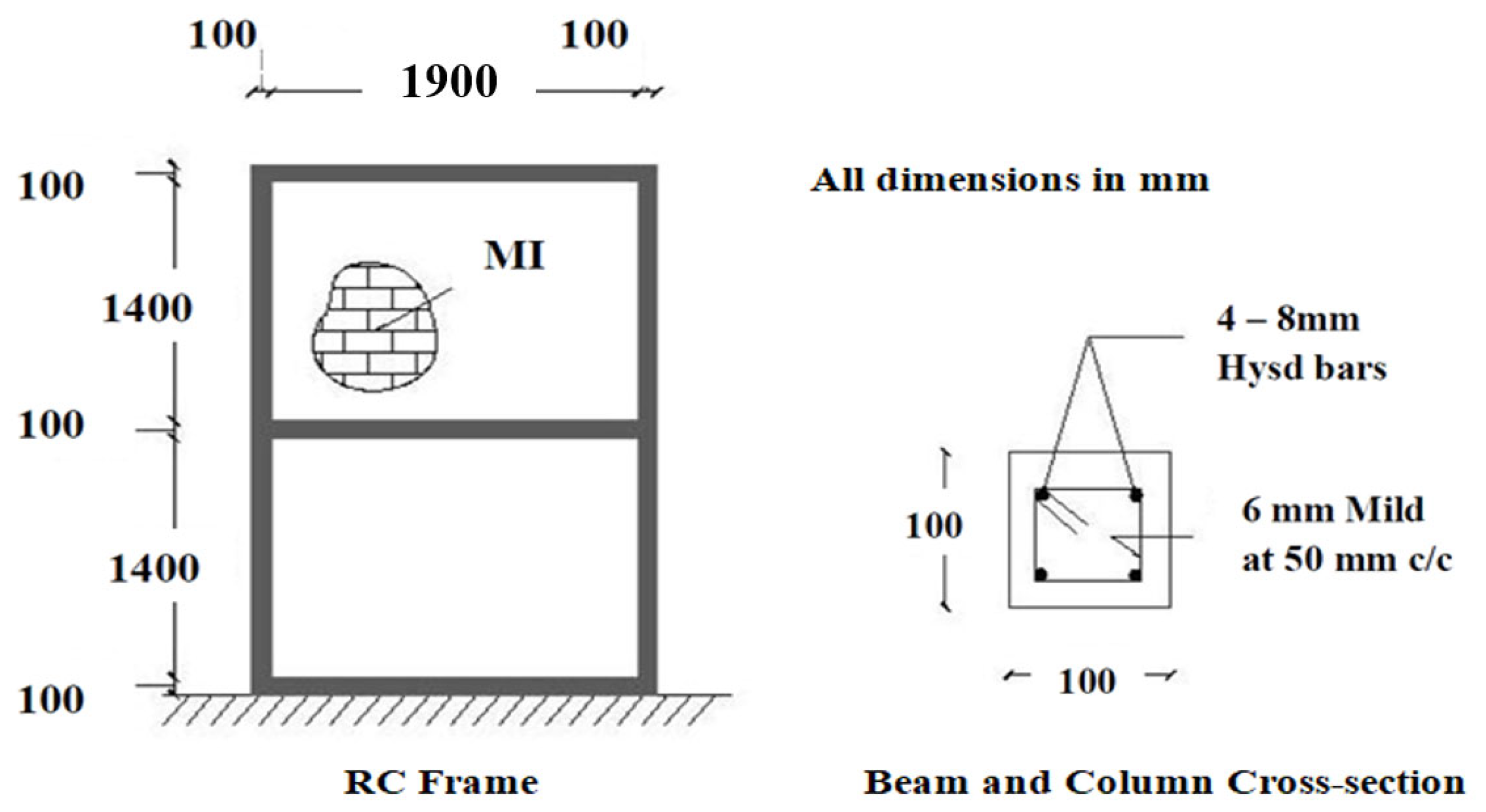
The columns and beams in RC frames have 100 mm × 100 mm cross-sectional dimensions along with 8 mm high yield strength deformed bars with 6 mm mild steel stirrups at 50 mm center to center, as shown in
Figure 1. The steel reinforcement in the framed section conformed to IS 1390-1993 [
18], and using locally available table-molded bricks, brick masonry in cement mortar 1: 6 was used as the infill wall.
2.2. Characteristics of Materials Used in the Experimental Program
Due to the scaled structures, the RC-framed structures had closely spaced reinforcements and were also small in dimension. Hence, to facilitate the placement of concrete, self-compacting concrete (SCC) was used to avoid the vibrations of concrete. Ordinary Portland cement (OPC 53 grade) conforming to IS: 12269-1987 [
19] requirements was used. Manufactured sand (M-sand) was used as fine aggregate, and ground granulated blast slag (GGBS) was used as filler material. The coarse aggregates used were 12.5 mm downsize, and a dosage of 1.15% super-plasticizer Master glenium-Sky 8233 was used to achieve the target strength of 40 MPa after 28 days of curing, as per IS 10262:2019 [
20]. The GGBS was used as a partial replacement of cement at about 35%, and the workability of SCC flow was maintained at between 700 mm and 800 mm. A cement content of 300 kg/m
3 and water–cement ratio of 0.6 was adopted, as per IS 456:2000. This mix was used to prepare all three MI-RC models cast in this study. However, the concrete cubes which were tested at the time of the cyclic loading test of MI-RC frames indicated a cube strength crushing strength of 46.22 MPa, which was slightly more than the target strength.
Standard molded bricks available in the South Indian Bangalore region were used in this experimental study, having a unit strength of 7.6 MPa. Brick masonry was constructed using cement mortar 1:6 along with a water–cement ratio of 1.2. The brick masonry assemblages were cast, cured for 28 days and tested under compression to evaluate the properties of masonry assemblages. The SCC and cement mortar were tested, and the material characteristics used in the models are tabulated in
Table 1.
2.3. Estimation of Failure Lateral Load
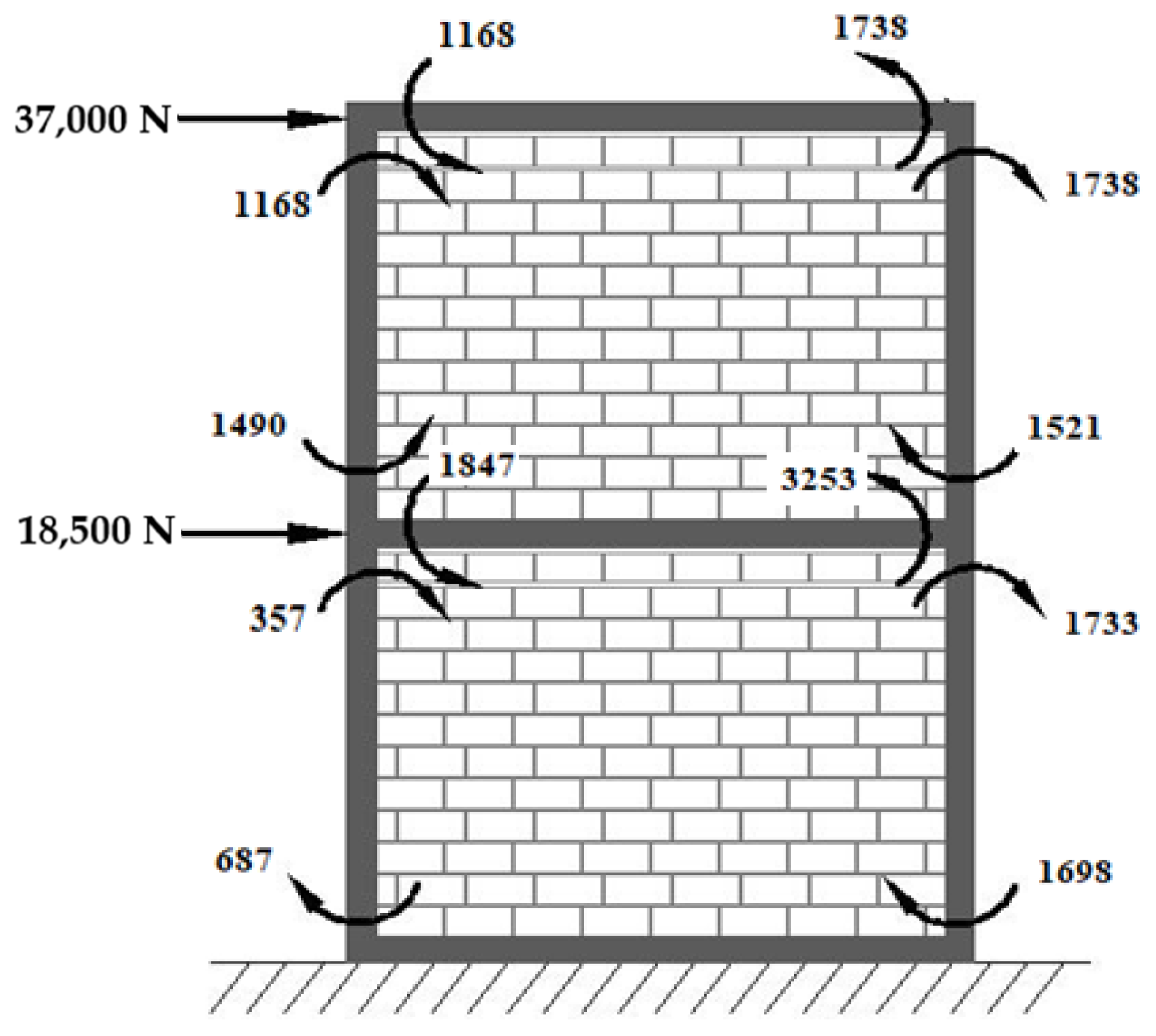
The capacity moment of RC members can be computed for the test specimens with the achieved strength of concrete using the ultimate load method. Here, the bending compressive stress distribution of concrete is assumed to be parabolic with a maximum compressive strength of 0.67 fck for the achieved grade of concrete, and the strain was assumed to be linear across the depth of the section. The yield stress of corresponding steel used was taken as 415 MPa. Using these parameters, the ultimate moment capacity of the RC section under flexure was assessed to be 3249 N-m for the achieved strength of concrete grade which has been reported in
Table 2.
The prime focus of this present experimental investigation was to study the behavior of the lateral load response of MI-RC frames reinforced with geo-fabric at interfaces under in-plane lateral loads. The lateral load capacity of any model which was also equal to respective base shears was estimated using the equivalent lateral load method conforming to IS 1893:2016 [
21]. For the present experimental models, including the MI-RC frames, MI-RC frames with geo-fabric at interfaces and MI-RC frames reinforced with geo-fabric interfaces with a soft story, the base shear and equivalent lateral loads were estimated using the fundamental period of vibration and response spectra of the models.
Eigen value analysis of the models was performed on three models; the fundamental period of vibrations was found to be 0.05 s, 0.045 s and 0.13 s for MI-RC, MI-RC with geo-fabric as interface reinforcement and MI-RC with geo-fabric as interface reinforcement with an open ground story (soft story), respectively. In this present study, only dead loads due to concrete and brick masonry infill have been considered, and the calculated seismic weight on the frame was found to be 13.1 kN. The corresponding spectral acceleration co-efficient (sa/g) for all three models as per IS 1893:2016 [
22] was worked out as 2.5. The calculated design base shear of all the models was 55,000 N, and based on the design base shear, the calculated design load forces of the first and second stories were found to be in the ratio of 0.5:1.
Static lateral load analysis of the models subjected to the combination of loads (dead + lateral) was carried out. The lateral load was applied to the models in the ratio of 0.5:1 on the first and second stories of the frame. Further, through a trial-and-error method, the magnitude of the lateral load which could produce the maximum bending moment in beam–column joints equal to the ultimate moment of resistance of the sections was determined. Here, the frame was analyzed using standard FEM software where the column and beam were considered as line elements, MI was considered as a four-noded shell element and the interfacial element was considered as a rigid element. The theoretical evaluation of the base shear was conducted to have a rough estimation of the maximum lateral load that might cause failure of infilled frames, and no redistribution was considered.
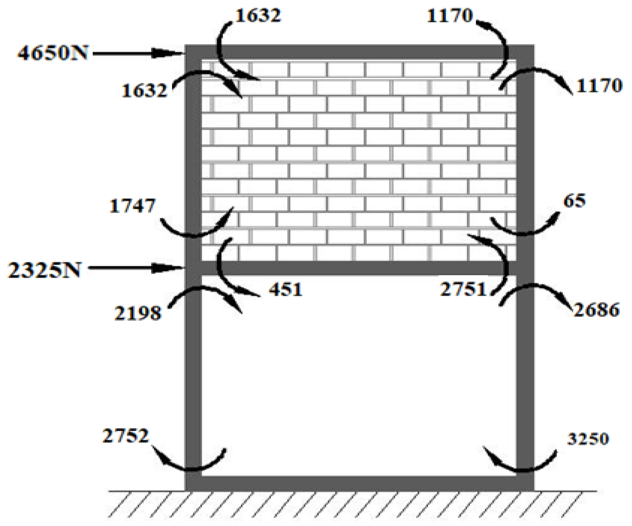
The expected bending moments developed at the beam to column joints due to applications of lateral loads for the considered MI-RC frames are shown in
Figure 2 and
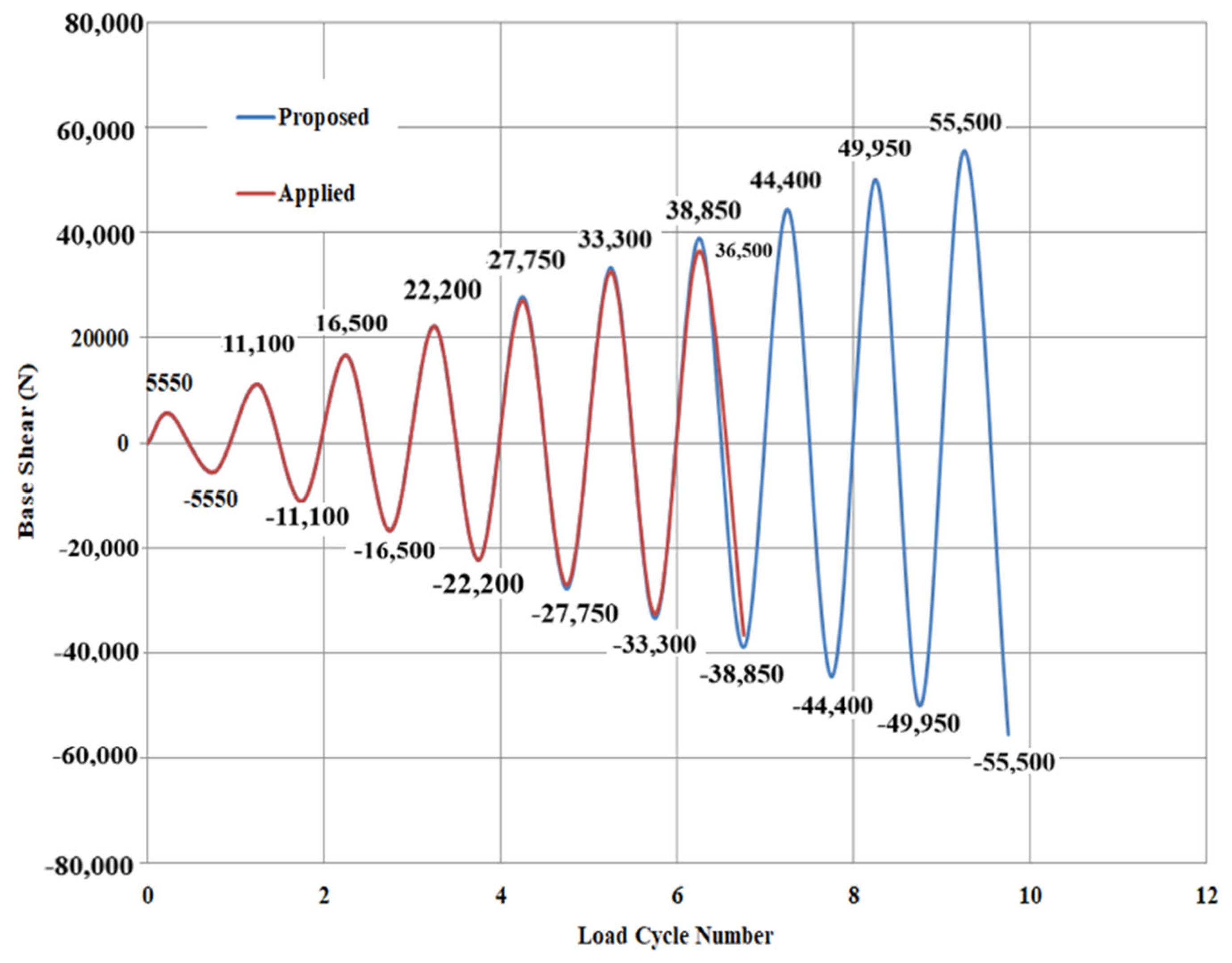
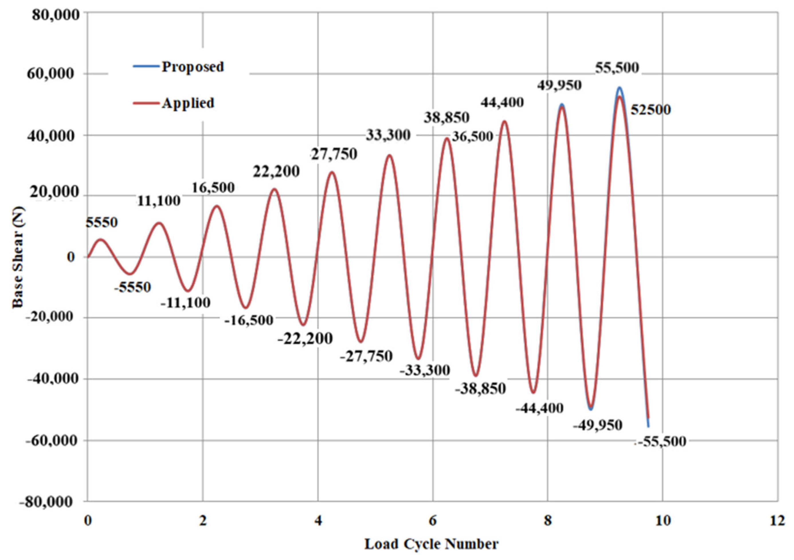
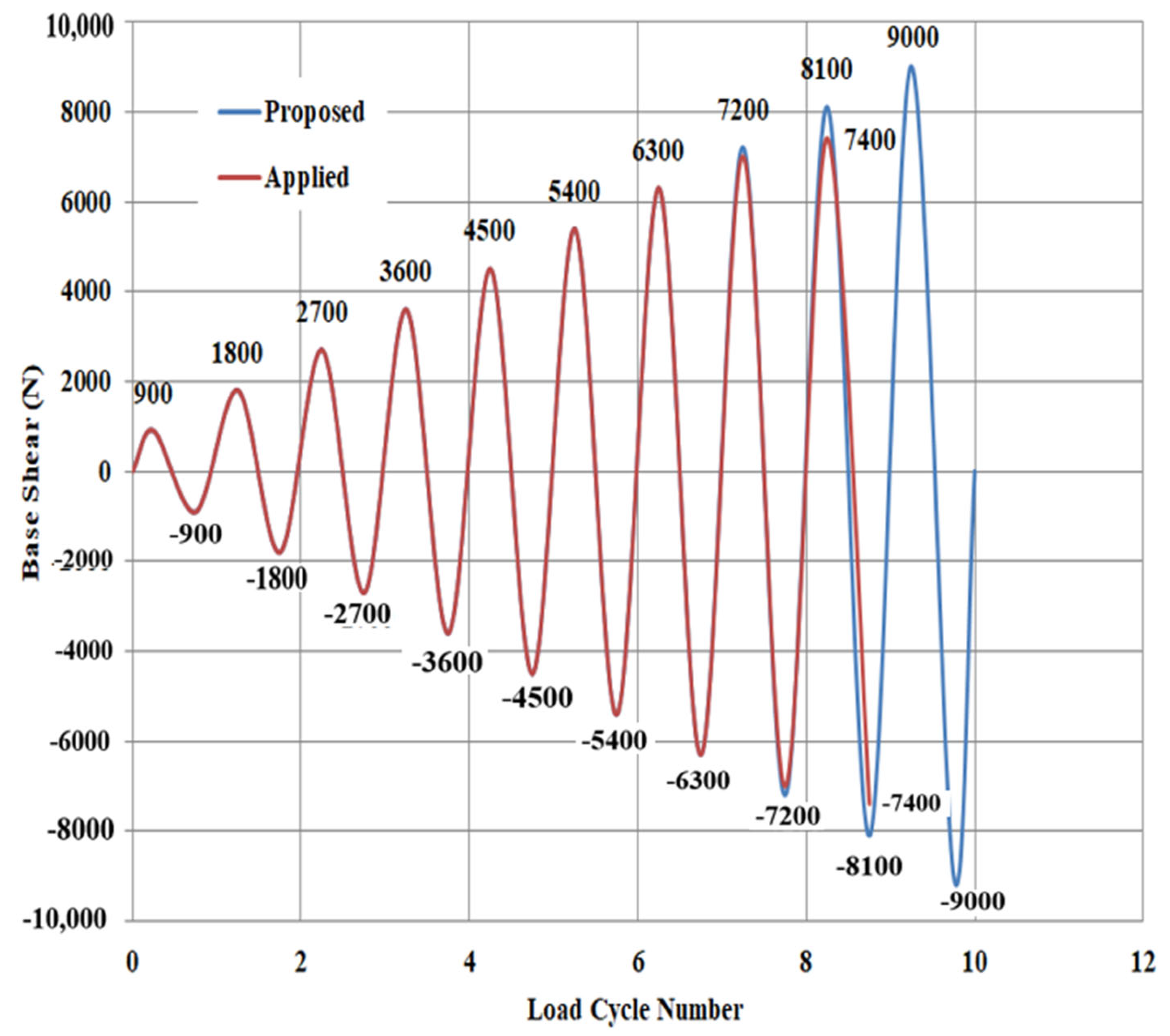
Figure 3. The summations of lateral loads (base shear) applied to models are estimated as theoretical failure lateral loads for respective models, and the same has been represented as respective cycles of increasing magnitude, as shown in
Figure 4,
Figure 5 and
Figure 6.
2.4. Experimental Setup and Proceedings
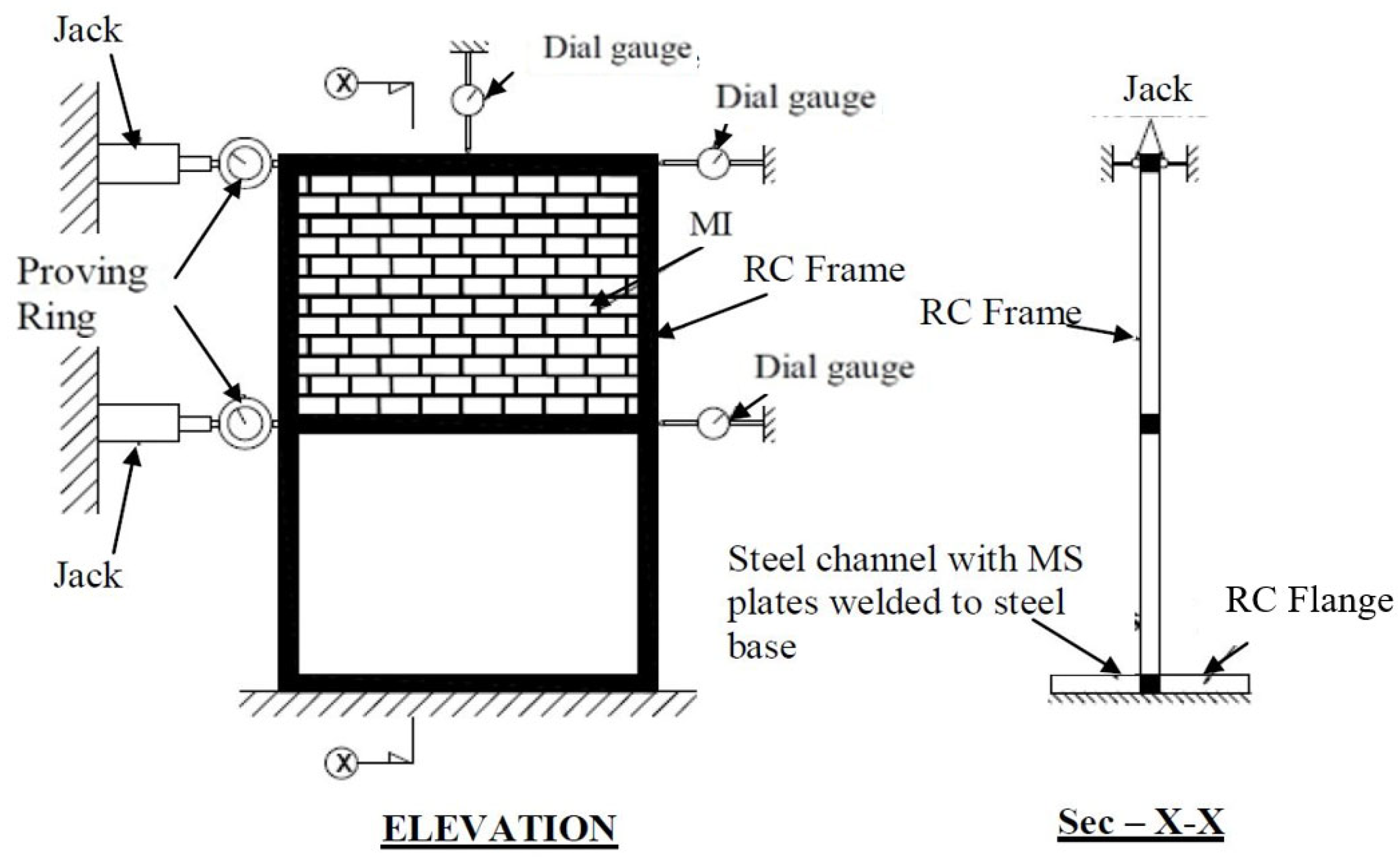
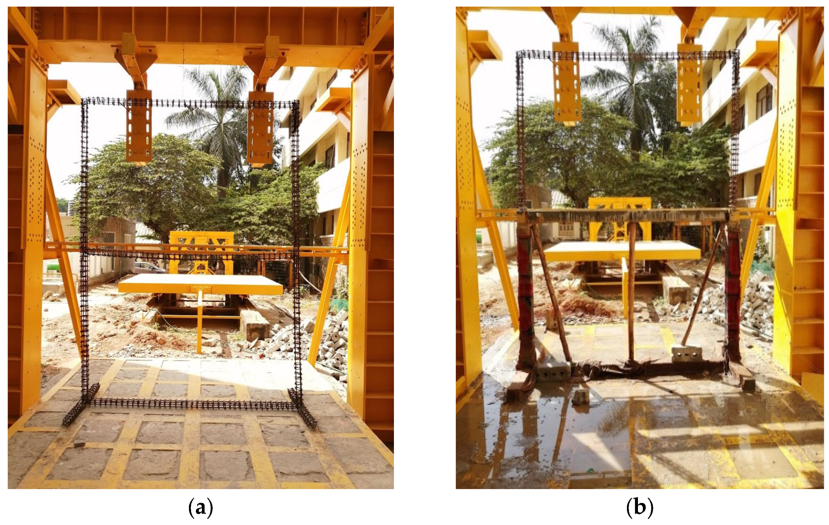
The RC frames were provided with RC flanges of 450 mm in length on either side of the column having a cross section of 100 mm × 100 mm to facilitate the fixity conditions at the base. The RC flanges were firmly fixed with the help of mild steel channels and plates which were welded at the base of the loading frame. The bottom flanges were clamped at the base using lipped channels, which were anchored using 12 mm diameter anchor bolts. Fixity was provided at the bottom of the RC frame. To ensure the proper application of in-plane lateral loads on the MI-RC frame, the frame was connected with suitable restraint arrangements with the help of an I-section and a roller hung at the top of the beam. The restraints helped to control the probable out-of-plane deformation of MI-RC models and also helped to ensure that the models were subjected to only in-plane lateral loads. All three models were checked in same way and tested under a 2000 kN loading frame for reversed cyclic lateral loads. The testing models along with the experimental setup are shown in
Figure 7,
Figure 8 and
Figure 9.
The loads were applied to the RC frame with the help of manually operated jacks which were mounted at each story level. The jacks were mounted with proving rings at each story level, and the lateral loads were applied at the bottom and top stories at a rate of 0.5:1. The maximum base shear of each cycle shown as per loading history (
Figure 4,
Figure 5 and
Figure 6) was applied using the equivalent static lateral load method to each model. The loads were increased stepwise up to the maximum value, and later, the lateral load was unloaded in a similar fashion. During sequential loading, the corresponding story drift and deflection of beams were recorded using digital dial gauges. The directions of the in-plane lateral loads were reversed from the other end of the model, and the corresponding story drift and deflections were recorded for the applied loads at each story level. In each first half of the cycle of loading, the lateral loads were gradually applied up to the maximum value, and the same procedure was repeated in the second half of the cycle of loading by reversing the loading direction for the same magnitude of lateral loads.
The specimen fabrications were conducted under the 2000 kN loading frame. In the first stage, reinforcement skeletal frames were constructed, and SCC was used to cast the RC frames. In the case of conventional construction, brick masonry was constructed after water curing the RC frame for 28 days. All three specimens were allowed to cure for 28 days with the help of gunny bags after the completed construction of the MI-RC frames.
Before the construction of masonry panels, the locations on column faces connecting the geo-fabric were identified using a rebar locator. After identifying the locations, the geo-fabrics were connected with the help of washers and 3 mm diameter bolts using mechanical drill bits. At every course along the bed joints, 400 mm lengths of geo-fabrics were laid and connected at the interface of the column. The length of the geo-fabric was restricted because the provision of openings in infill may be possible practically, and the prime focus of this study is the interfacial study of RC and infill panels. The casting technique of geo-fabric reinforcement and the construction of the MI-RC model is shown in
Figure 10a–f.
Flexible polyester geo-fabric is used as a reinforcing material at the interface of the MI and RC frame. Polyester-type geo-fabrics are very easy to handle, non-corrosive and extensively used in the field of soil reinforcements. Hence, an attempt is made in this present experimental investigation to study the behavior of an MI-RC frame using polyester geo-fabric as an interfacial reinforcing material.
3. Results and Discussion
One-bay two-story MI-RC frames are considered in the present experimental investigation. An MI-RC frame reinforced at interfaces with geo-fabric on both stories was considered in the first model, and reinforcement at the interface of MI-RC with geo-fabric only on the top story and provided bottom soft story (open ground story) was considered in the second model. The third model is a conventional MI-RC frame with only brick MI on both the top and bottom stories. The three types of models are investigated for their story drift, stiffness degradation and ductility; energy dissipation and modes of failure when subjected to cyclic in-plane lateral loads have been discussed in the following section.
3.1. Microstructural Behavior of SCC Used in RC Frames
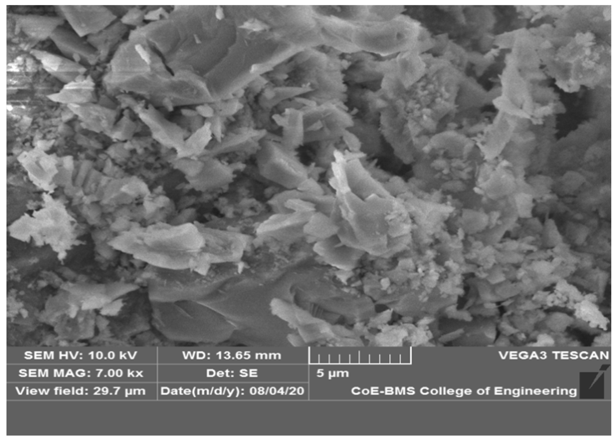
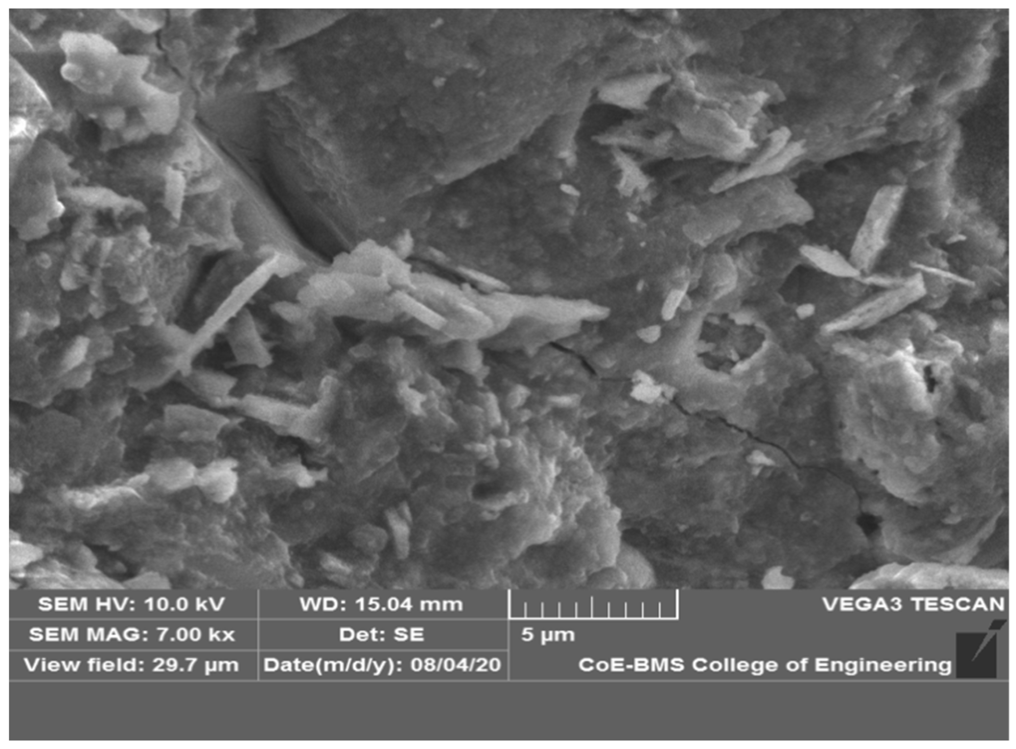
The SCC was prepared using GGBS as a filler material. The hydration of cement plays a major role in attaining target strength, and microstructural observations help us to know the actual behavior of the cement paste. To know the behavior of the cement paste in all three MI-RC frames, microstructural images were considered to observe the internal morphology of cement paste. The concrete cubes which were tested at the time of the cyclic loading test of the MI-RC frames were subjected to microstructural analysis after the test. The test specimens were extracted after the cube strength test. The size of the specimens considered for the analysis was 10 mm × 10 mm, and the microstructural images considered in each frame samples are shown in
Figure 11,
Figure 12 and
Figure 13.
The hydrated cement paste microstructures of frames presented in the figures above are considered at a five-micron level for each frame. It can be observed that mix M40 has sufficient hydrated phases in its microstructure. There are a few un-hydrated components observed as bright spots in all of the microstructural images. In comparison with
Figure 11 and
Figure 12 with concrete frames, the microstructure of concrete exhibits similar phases of hydrated and un-hydrated cement mass in its microstructure. All the three RC frame mixes resulted in the uniformity of microstructure with an observable presence of capillary voids.
The overall SEM studies showed consistency in the mix quality of the prepared grade of concrete (M40) in terms of its microstructure. There was not a considerable variation or presence of anomalies from the point of observation of all three RC frame concrete mixes.
3.2. Story Drift
The relative displacement of the frame with respect to one level to another level above or below the story is referred to as story drift. Generally, drift has been defined as the total lateral displacement at the top of the building, and the relative lateral displacement between the consecutive story levels is termed as inter-story drift. Top story drift plays a major role in the case of analysis and design of high-rise buildings, and they are subjected to this mainly under lateral loads.
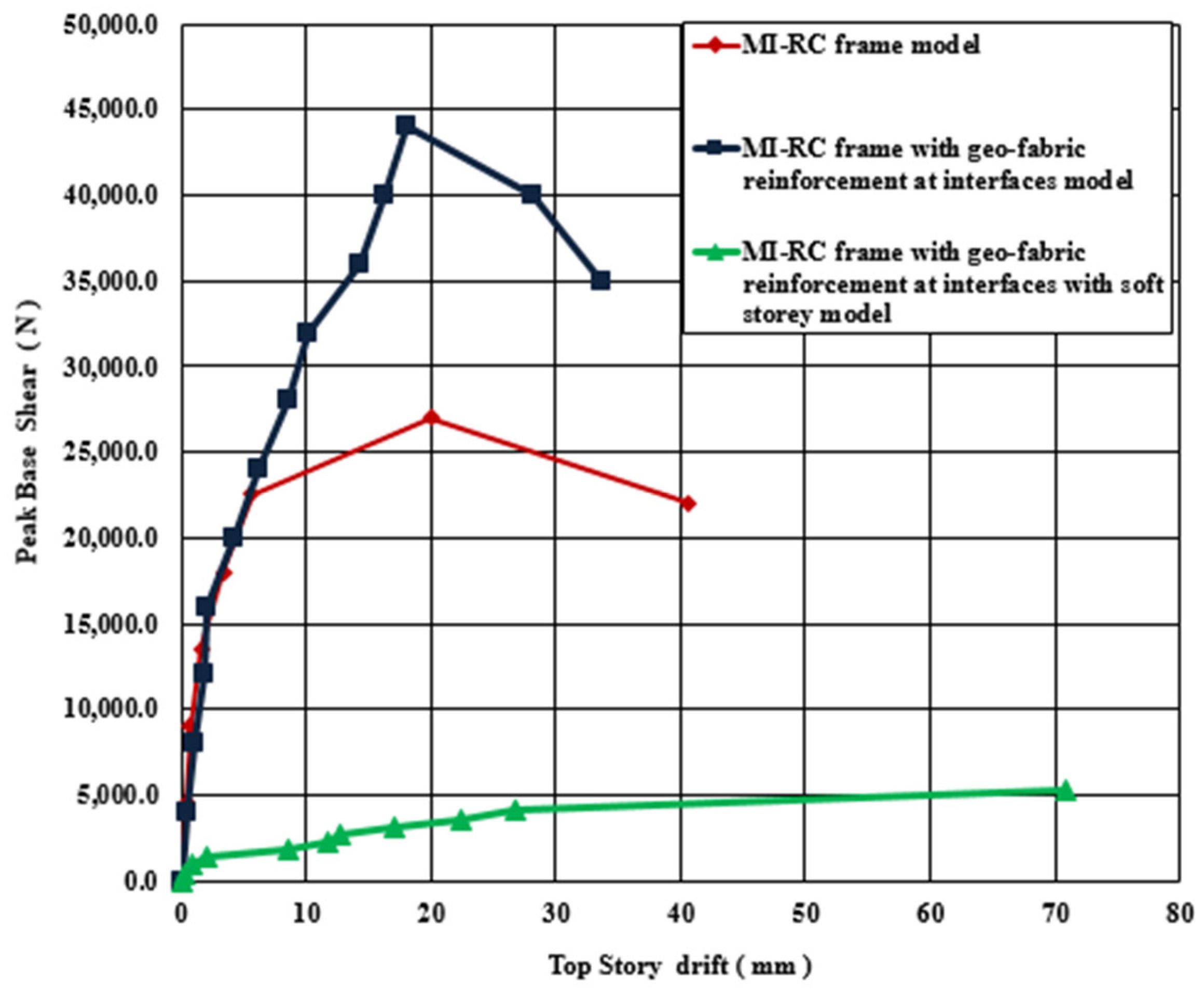
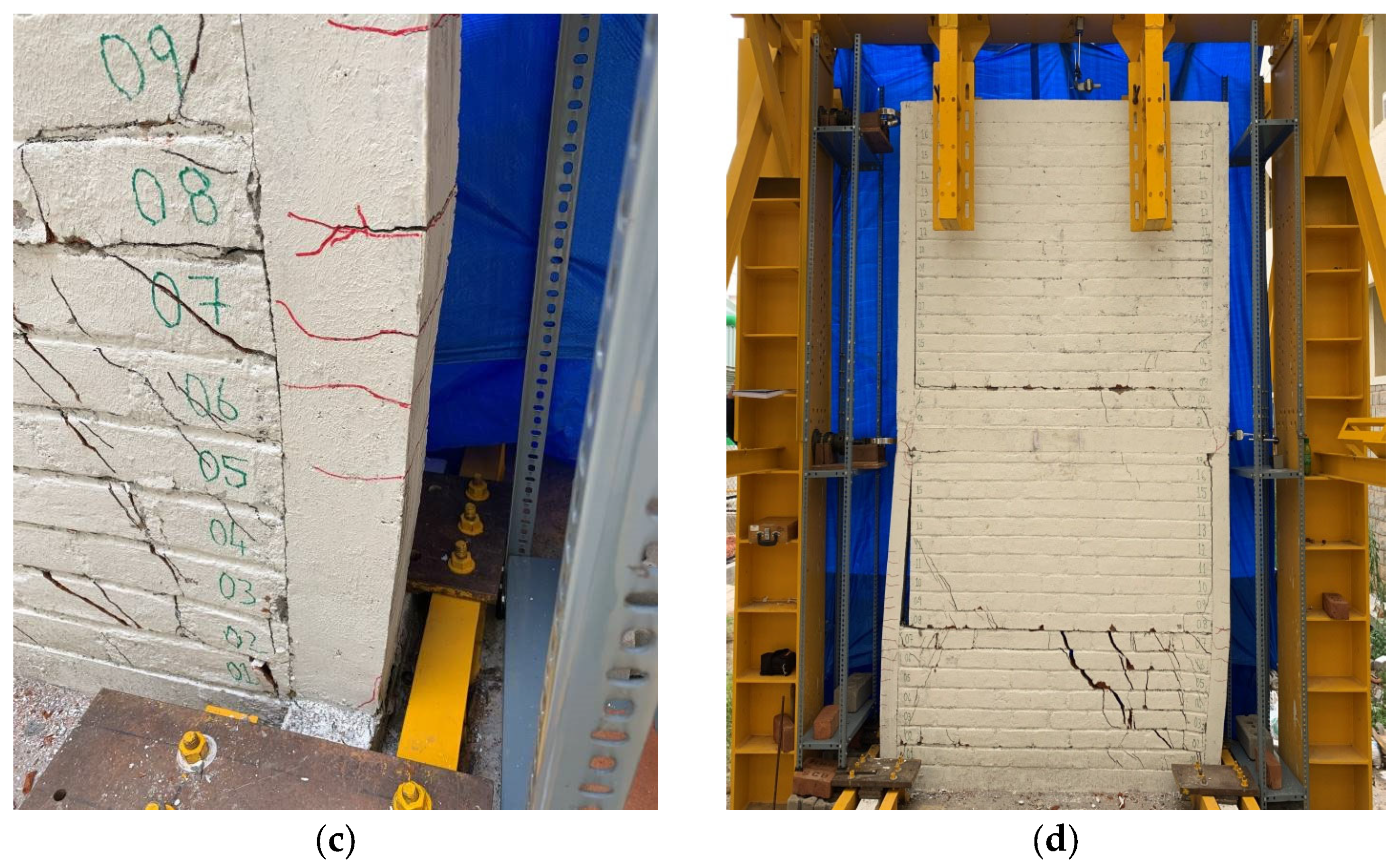
The conventional unreinforced MI-RC frame was subjected to maximum base shear of 27,000 N in the sixth cycle. During the fourth cycle of loading, the MI lost contact with the RC frame at the interfaces of the bottom story. It was observed that in the fifth load cycle, the MI in the bottom story failed by indicating horizontal shearing of mortar bed joints. Further, larger values of lateral drifts were observed from the fourth to the sixth cycles of loading due to separation of the MI from the RC frame. After reaching maximum story shear in the sixth load cycle, the top story drift increased gradually, and the base shear reduced to around 50% of the maximum value in the subsequent cycles of loading.
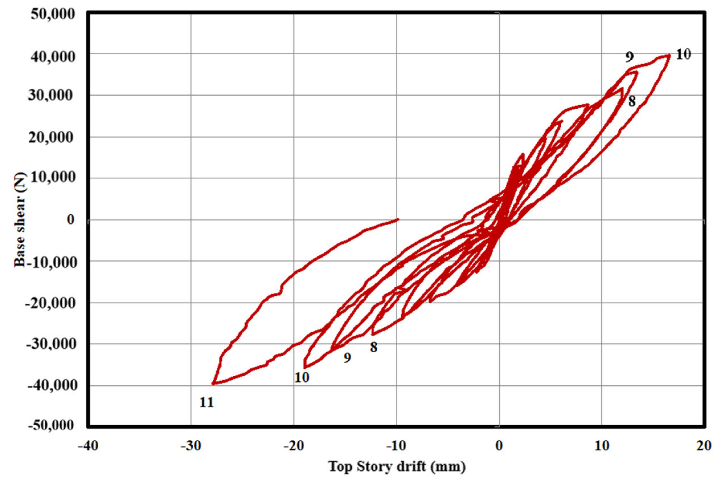
The MI-RC frame with geo-fabric reinforcement at the interfaces model was subjected to a maximum of 11 load cycles with a maximum base shear of 44,000 N. The first crack appeared on the interfaces in the 5th cycle of loading, but the cracks widen after the 10th cycle. The geo-fabric’s contribution to holding the MI and frame together as a single integral unit was observed between the 5th and 10th cycles of cyclic in-plane lateral loading of frames. Horizontal bed joint failure was observed in the MI in the 10th cycle of loading at the bottom story, and a horizontal crack on the face of the columns was also observed at the bottom story of the frame. Plastic hinge deformation was observed at the beam–column junction in the 10th cycle, and lateral drift was observed to be slightly increased between the 7th and 10th cycles of loading. The interface connection was lost in the 11th cycle of loading, and horizontal bed joint sliding was observed on the top story of MI in the same cycle of loading.
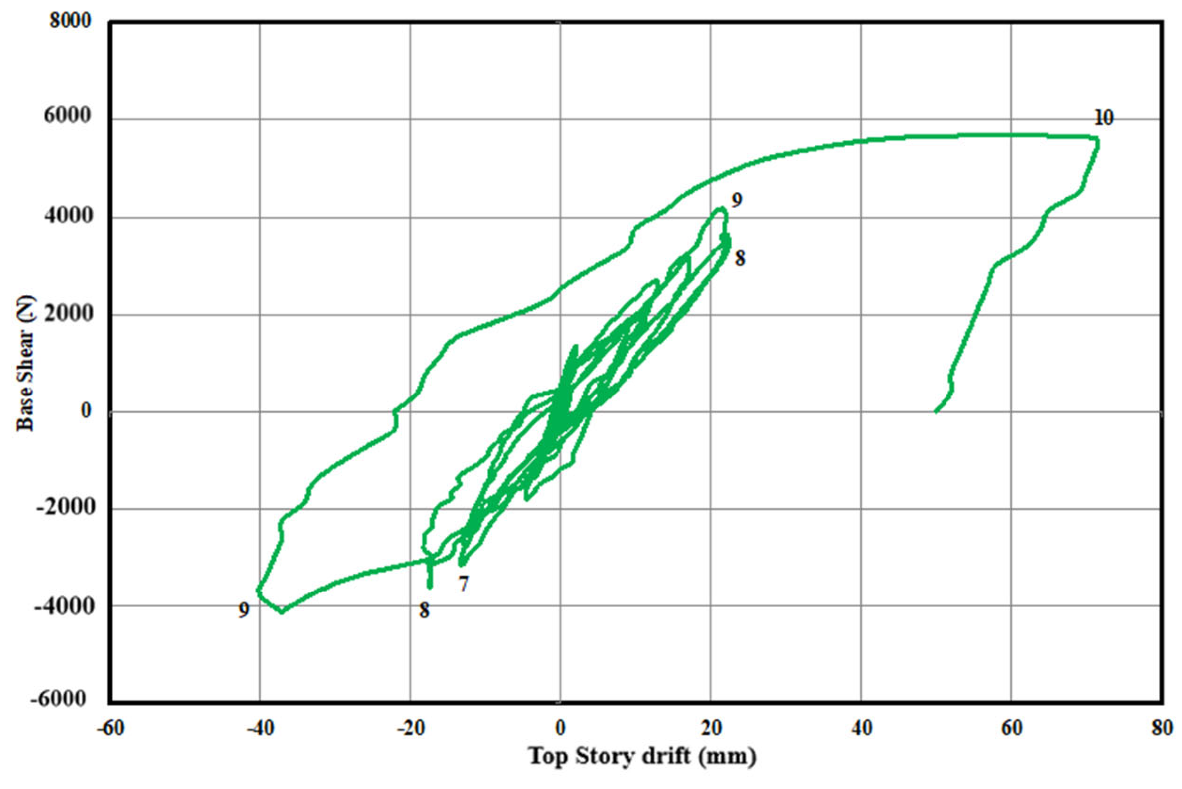
The MI-RC frame reinforced with geo-fabric at interfaces in the top story with open ground story model was subjected to a maximum base shear of 6050 N in the ninth cycle of loading. It has been observed that during the maximum cycle of loading, MI was not detached at interfaces of the top story, and only open ground story columns failed because of less stiffness. After the ninth cycle of loading, the model loses its lateral-load-resisting ability, and crushing of the column is observed at the bottom of the soft story due to the development of larger moments. A horizontal crack was also noticed on the face of the column at the bottom story, and X-type cracks were observed at the beam–column junction in the 10th cycle of loading.
Figure 14 shows the top story drifts of the MI-RC frames for the ultimate story shear with respective models. It indicates that the model with an open ground story exhibited the highest amount of top story drift, while the model reinforced with geo-fabric at interfaces of MI-RC exhibited the least. It can be noted that expectedly, the deformation of the open ground story model was two times that of the geo-fabric reinforced at interfaces model. Hence, from the experimental studies, it is noticed that geo-fabric reinforcement at interfaces of MI-RC helps to improve lateral-load-carrying capacity and controls lateral drift effectively under in-plane lateral loads.
3.3. Stiffness Degradation
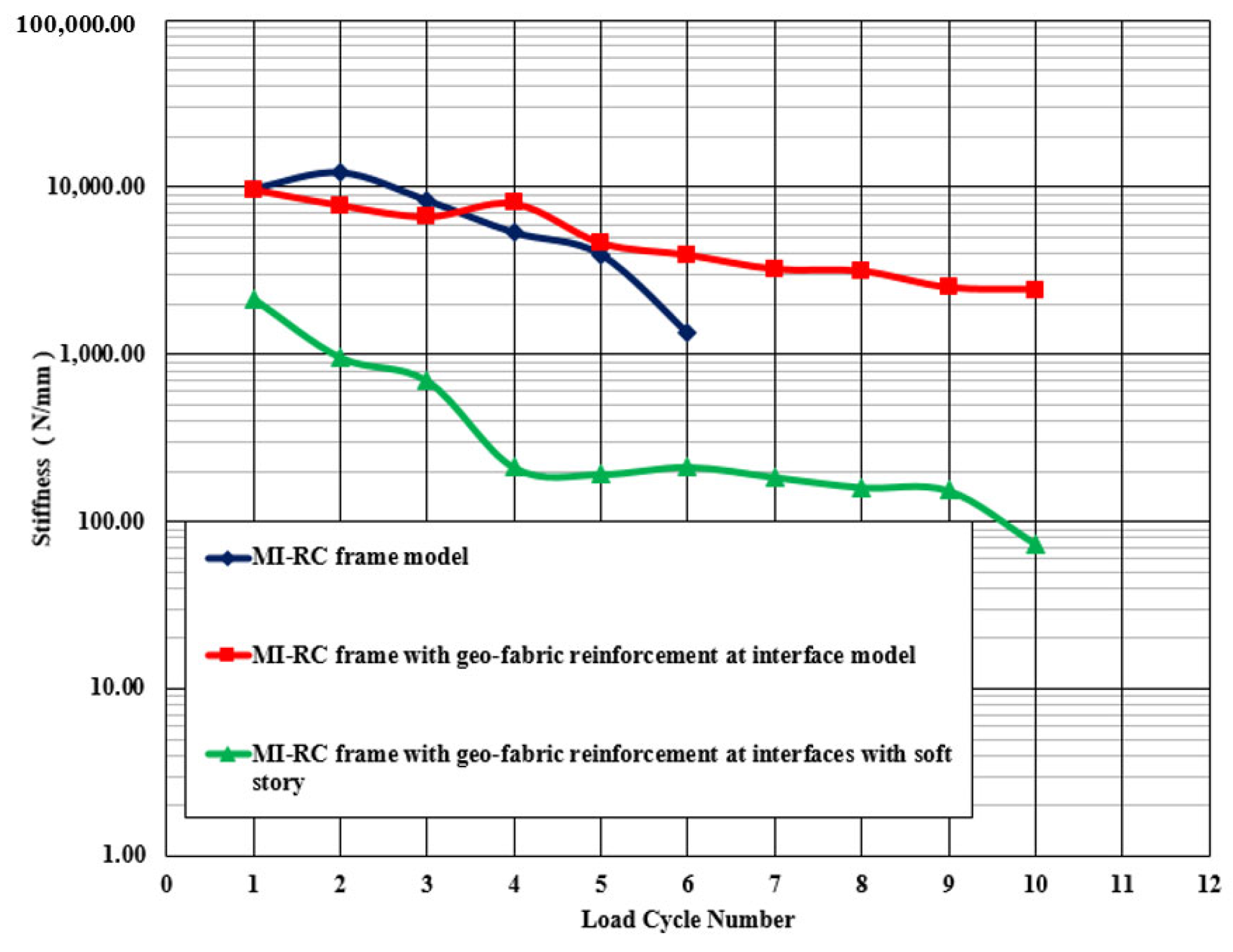
The slope of the load deflection was used to measure the stiffness of the models. An initial stiffness of 10,000 N/mm was observed for the conventional MI-RC and reinforced MI-RC models, while the open ground story model exhibited an initial stiffness of only 2065 N/mm. The stiffness of the MI-RC model decreased gradually after the 3rd cycle, and the residual stiffness recorded at the end of the cycle was 1090 N/mm. The bottom story MI suffered with failure cracking of the horizontal bed joint and stepped crack failure in the fourth cycle of loading, and hence, the stiffness of the MI-RC model decreased because of the failure of the masonry infill.
Expectedly, the geo-fabric reinforced at interfaces MI-RC model performed better than the conventional MI-RC model. In the 5th cycle of loading, the interface failure mechanism was observed in both the models, but the geo-fabric-reinforced model showed better consistent performance in stiffness up to the 8th cycle, and even the residual stiffness was 1340 N/mm, which is high when compared with the MI-RC model. The presence of geo-fabric enhanced the stiffness behavior of the MI-RC frame. The bed joint failure mechanism was observed in the ninth cycle of loading at the bottom story in the unreinforced bed joint regions.
The MI-RC model reinforced with geo-fabric with open ground story model is relatively very flexible at the bottom story such that initial stiffness was 2065 N/mm, which is only 10.5% of the initial stiffness of the other 2 models. The stiffness steadily decreased up to the fifth cycle and thereafter at a faster rate because the RC frame had developed X-type cracks at the beam–column junction, and shear cracks were also noticed in the columns. The residual stiffness of the frame at the end of 10th cycle of loading was 90 N/mm, which is much lower than that of the other types of models.
Figure 15 shows the stiffness degradation of all the three types of MI-RC models tested corresponding to in-plane reverse cyclic loading. It can be noted that conventional MI-RC and geo-fabric-reinforced MI-RC models’ initial stiffness is 80% more than that of the open ground story model. This clearly indicates that the infill plays a major role in contributing stiffness under lateral loads. The open ground story model exhibited lesser stiffness; even the top story MI was reinforced with geo-fabric at interfaces.
3.4. Ductility
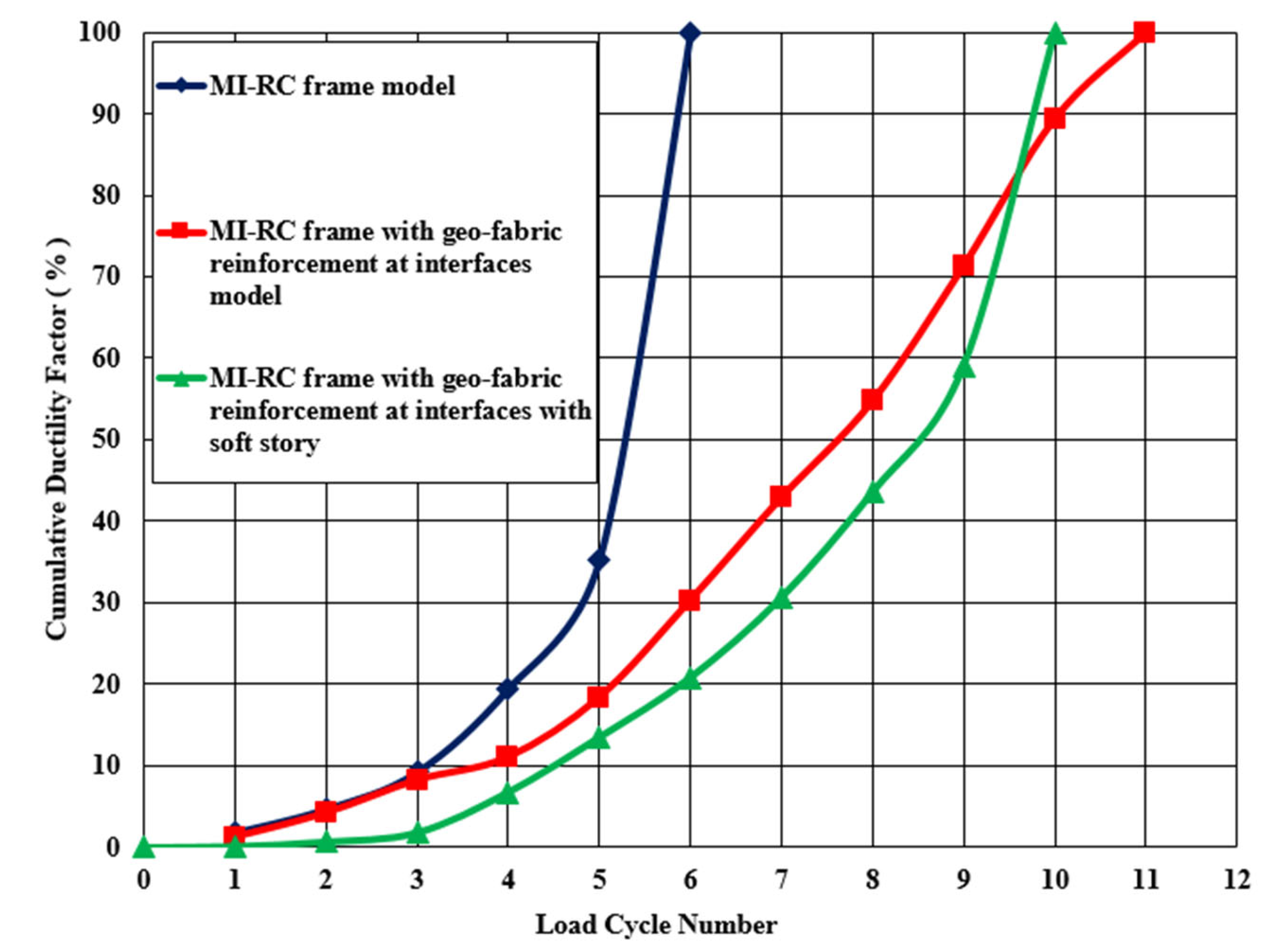
Ductility is a measure of the material’s ability to undergo permanent deformation without fracture. In all three MI-RC frame models, the ductility factor is considered for evaluation, and it is the ratio of failure displacement to yield displacement. In the present section, top story drift was considered for the evaluation of ductility factor, and calculated cumulative ductility factor is defined as the total sum of ductility factor at maximum base shear levels in each cycle up to the load cycles considered.
The conventional MI-RC frame model exhibited an appreciable top story drift during the 4th cycle of loading, and a drift of 3.37 mm is considered as the yield drift of the MI-RC frame. The load–displacement behavior of the MI-RC frame model is shown in
Figure 16, and it is evident from the chart that the frame has displaced more after the fourth cycle of loading. In the same loading phase, the MI separated from the RC frame at interfaces, and crack sizes increased in the MI of the bottom story.
The MI-RC reinforced with geo-fabric at interfaces model had a yield drift of 1.9 mm in the 5th cycle of loading, which was much lower than that of the conventional MI-RC frame.
Figure 17 shows the load–displacement behavior of the model subjected to in-plane cyclic loads. It is evident from the load–displacement chart that the geo-fabric helped to control the lateral drift of the model by making the MI and RC frame an integral unit by strongly connecting them at the interfaces.
For the open ground story model, the yield drift was noticed in the 5th cycle of loading at a magnitude of 11.6 mm. Subsequently, cumulative ductility factors were evaluated, and the model lost its ability to resist deformation in the 10th cycle because of plastic deformation observed at beam–column junctions. It was observed that the presence of geo-fabric reinforcement at the interfaces of the top story and open ground story model did not have much impact on load-carrying capacity or on the prevention of lateral drift deformation. The load–displacement behavior of this case is presented in
Figure 18.
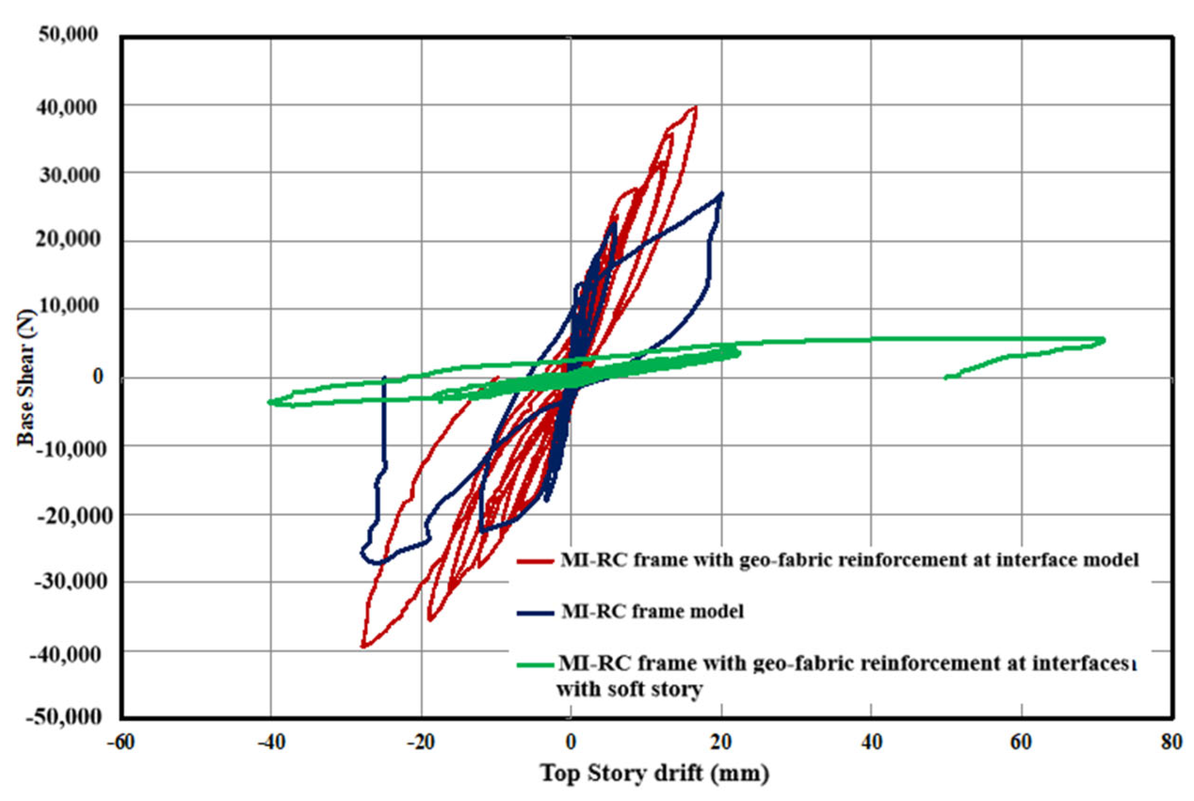
A generic comparison using the hysteretic curves for the three specimens is presented in
Figure 19.The cumulative ductility factor is presented in
Figure 20, and it is observed that after the eighth cycle of loading, the model lost its ability gradually, and this resulted in maximum deformation/drift.
3.5. Energy Dissipation
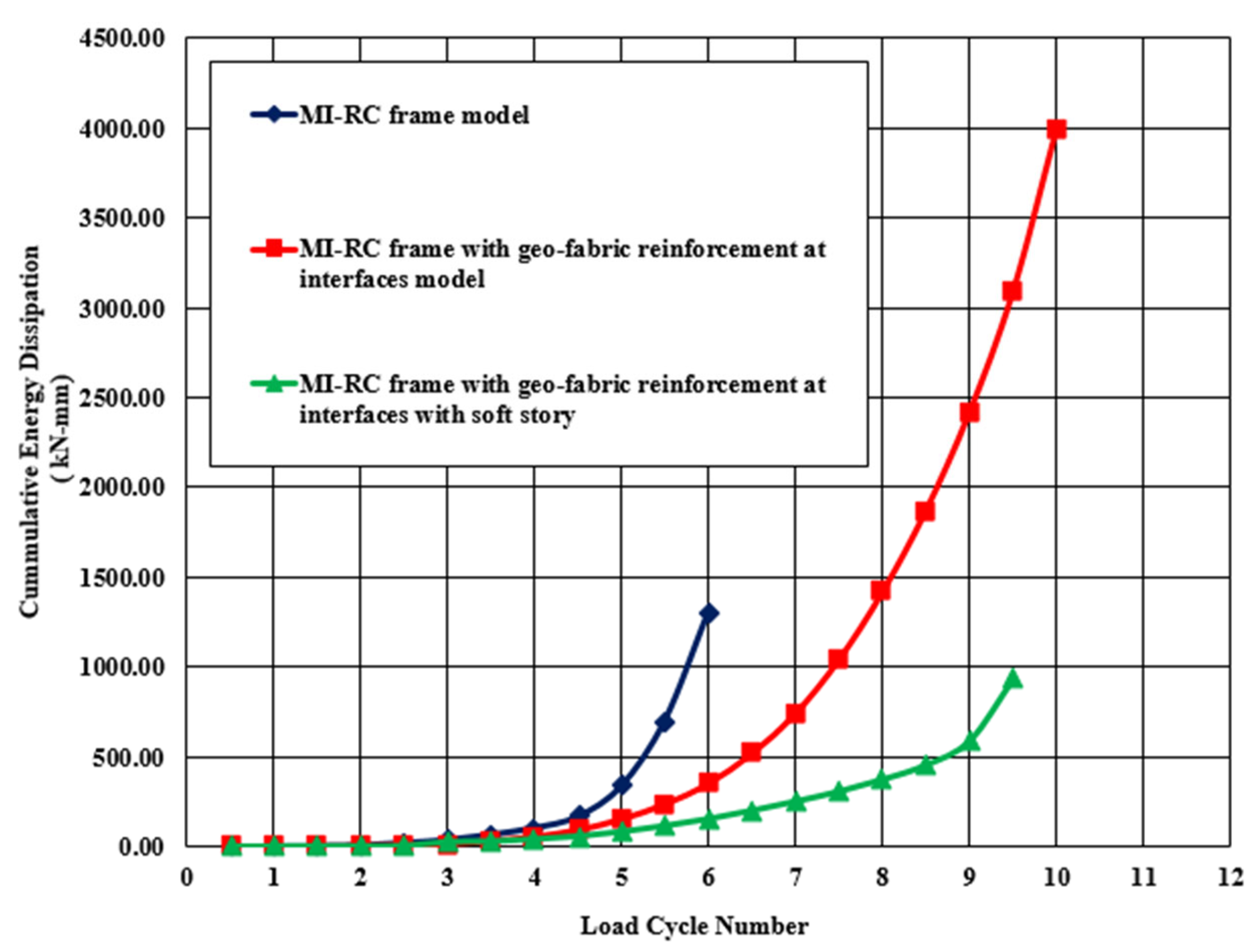
The energy dissipation in the case of the models tested is defined as the area enclosed by the lateral load displacement of the hysteresis loop for the in-plane cyclic lateral loads. It is considered as an important aspect to study the behavior of MI-RC frames under in-plane lateral loads. The main parameter used to study the energy dissipation is the load–displacement relationship. The energy dissipated by the conventional MI-RC frame model in the initial 1st cycle was 0.96 kN-mm, while the cumulative energy dissipated in the final 6th cycle of loading was 1306.75 kN-mm. The energy absorbed by the geo-grid reinforced MI-RC model in first cycle was 0.38 kN-mm, and the final cumulative energy dissipated at the end of the 10th cycle was 3990.68 kN-mm. It is also noted that in the case of the open ground story model, the energy dissipation was much lower. It had an initial cumulative energy dissipation of 0.46 kN-mm in the 1st cycle and 934.39 kN-mm at the end of the 10th cycle of loading. The cumulative energy dissipation chart is presented in
Figure 21.
The total energy dissipated by geo-fabric-reinforced MI-RC frames was about 2.5 times higher than that of the conventional MI-RC frames and 4.27 times more than that of the open ground story model. Geo-fabric reinforcement had no significance in the open ground story models.
3.6. Mode of Failure
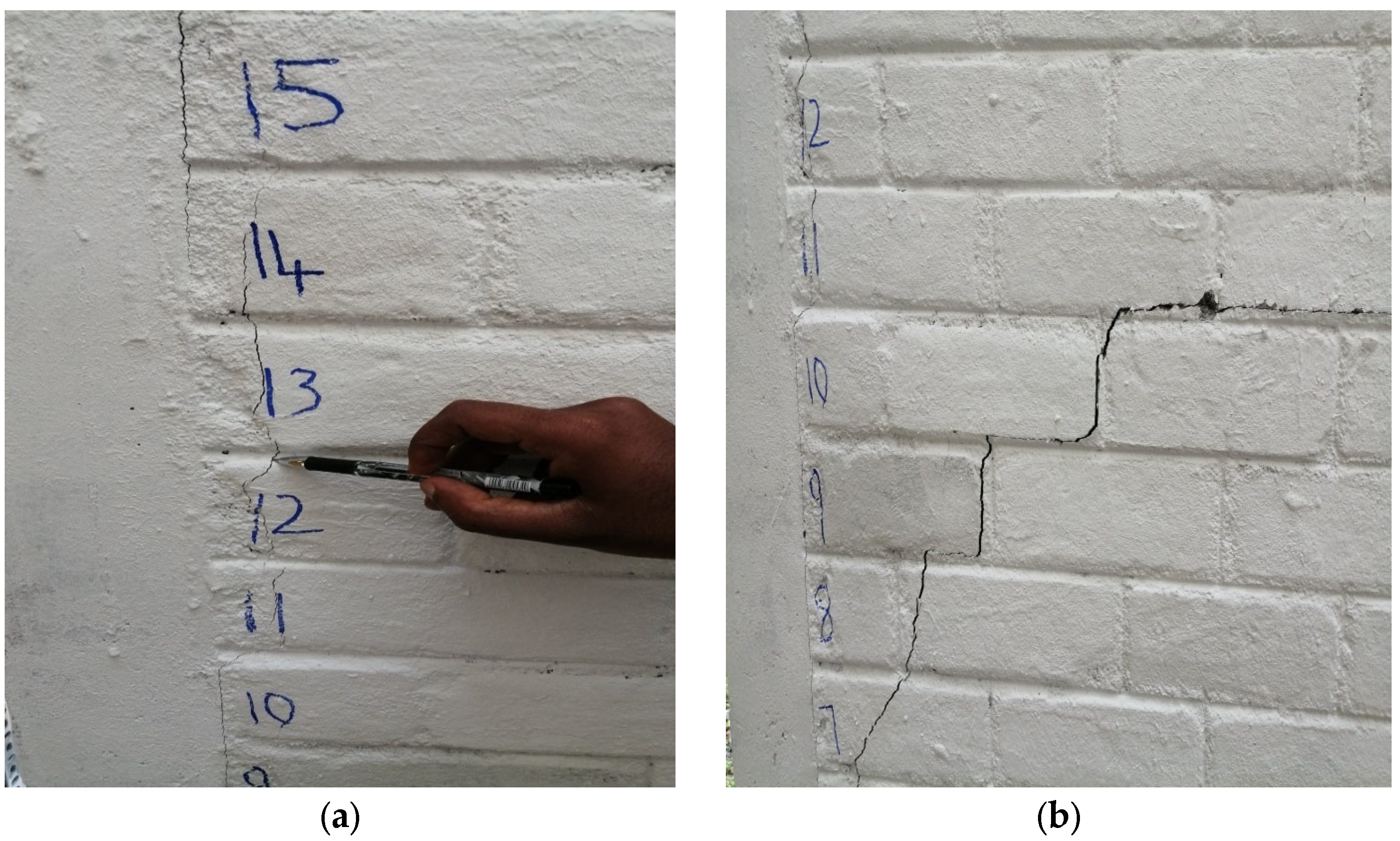
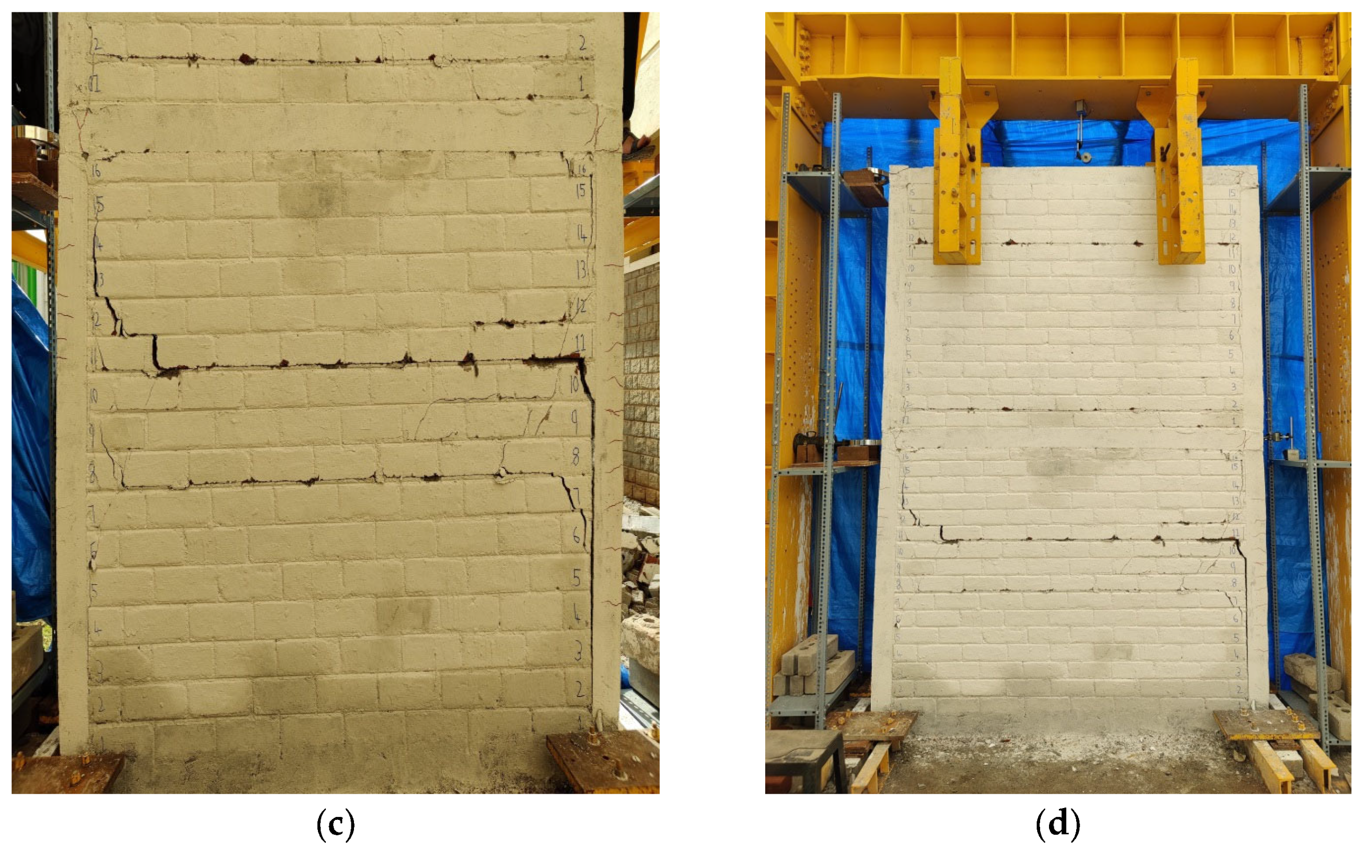
The first crack was observed in the case of the MI-RC model between the interfaces of MI and RC at the bottom story of the frame under the base shear of 22,500 N during the 5th cycle of loading, as shown in
Figure 22. After the interface detachment at the bottom story, the infill failed in a stepped way along with horizontal bed joint sliding. The various types of failures in MI such as sliding and bed joint failure were observed in the 6th cycle of loading at 25,600 N of base shear. In the same cycle of loading, the shear cracks were observed in columns and the X-type of failure was observed in the beam–column junction. On further loading, the frame experienced permanent deformation, and this resulted in a maximum drift of 20.01 mm.
The different failures that occurred in different cycles of loading are presented in
Figure 22. During subsequent cycles of loading, the frame lost its lateral-load-resisting ability, and the cracks widened at the MI. This resulted in maximum drift and eventually failure of the frame. There was a sufficient increase in the lateral-load-resisting ability of the geo-fabric-reinforced MI-RC frame model. The model exhibited a better performance between the fifth and ninth cycles of loading. Because of interfacial strengthening, the MI resisted the lateral loads with better energy dissipation capacity. The first interfacial cracks were observed in the fifth cycle of loading, and after the ninth cycle of loading, horizontal bed sliding and stepped cracks developed at the bottom story of MI. The final deformed shapes along with the different failure patterns observed under different cycles of loading are shown in
Figure 23.
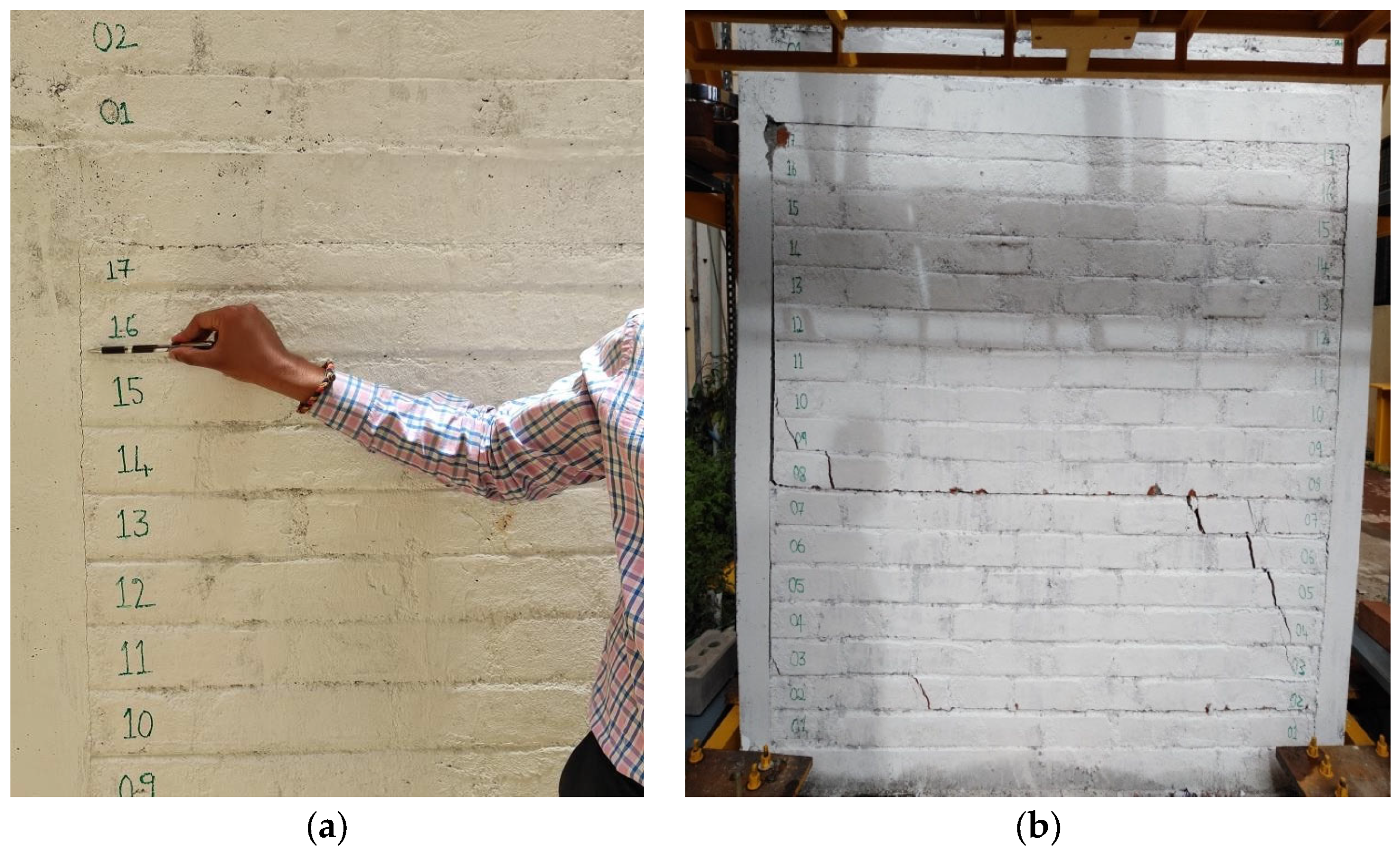
The geo-fabric-reinforced MI-RC model with open ground story showed decreased lateral-load-resisting capacity compared with the other two types of models. The bottom story experienced the lowest stiffness due to the open ground story, and the upper story, which was reinforced with geo-fabric, exhibited rigid body displacement in the initial cycles of loading. Initially, a horizontal crack was observed in the bottom of the column when base shear was 3600 N in the 8th cycle of loading. Upon further loading, cracks developed at the beam–column junction, and shear cracks were observed at the bottom of the columns. It was also observed that there was no major crack observed in the geo-fabric-reinforced MI interfaces at the top story. The final deformed shape along with the different types of failures is shown in
Figure 24.
In the MI-RC frame with an open ground story, geo-fabric reinforcement does not help to increase the lateral load capacity of the frame. The beam–column joints fail mainly because of a large moment developed because of MI at the junction. Further, these kinds of failures can be controlled by increasing stiffness in open ground story columns.
4. Summary and Conclusions
The three half-scaled models considered in this present study are the MI-RC frame model, the MI-RC frame reinforced with geo-fabrics at interfaces model and the MI-RC open ground story reinforced with a geo-fabric element. Based on experimental investigations, the following set of conclusions has been drawn.
The peak base-shear capacities of the conventional MI-RC frame model and the geo-fabric-reinforced MI-RC frame model were 27,000 N and 44,000 N, respectively. This indicates that the peak base shear capacity of the MI-RC frame with geo-fabric reinforcement is 163% of that of the conventional MI-RC frame model. The corresponding theoretically computed value is 55,000 N for both the models. Further, the peak base shear of the open ground story model reinforced with geo-fabric at the interfaces of the top story was 6050 N, compared to the theoretically computed value of 6975 N. It is clear that the presence of infill strengthened the interfaces of MI-RC, helping to enhance the lateral load capacity of MI-RC frames.
The maximum top story drift observed in the case of the conventional MI-RC frame model and geo-fabric-reinforced MI-RC frame model was 42 mm and 32 mm, respectively. It was observed that the maximum top story drift of the geo-fabric-reinforced MI-RC frame model was 76% of that of the conventional MI-RC frame model. Further, the maximum top story drift of the frame with an open ground story was 74 mm, which indicates the influence of masonry infill on the lateral drift of the model.
The initial stiffness of the MI-RC frame model and geo-fabric-reinforced MI-RC frame model showed a similar value of 10,000 N/mm, but after the 5th cycle of loading, the MI-RC frame completely lost its resistance against lateral loads. The geo-fabric-reinforced model showed consistent stiffness between the fifth and the eighth cycles of loading. Hence, this indicated that the presence of geo-fabric as a reinforcement at interfaces helps to enhance the stiffness and lateral-load-carrying ability of the MI-RC frame. However, in the case of the open ground story model, the initial stiffness was 2065 N/mm, which is 5 times less than that of the MI-RC frame model. This illustrates the influence of infill in enhancing the stiffness of the frame.
The geo-fabric-reinforced MI-RC frame model exhibited higher post-yield ductility, while the open ground story model exhibited that lowest post-yield ductility. Further, the energy dissipated in the geo-fabric-reinforced MI-RC frame model was 300% of that of the conventional MI-RC frame model. This is because of the performance of geo-fabric at interfaces, which helped to enhance the bonding behavior between the RC frame and the masonry infill. The energy dissipation capacity of the MI-RC frame model drastically decreased after the failure of the masonry infill.
In the case of the conventional MI-RC frame model, interfacial failure was observed in between the MI and RC frame. A brittle fracture of the masonry resulted in an increase in lateral loads on columns, which lead to shear failure at the lower story of the columns. In the case of the geo-fabric-reinforced MI-RC frame models, masonry failure was observed in a stepped pattern in unreinforced regions. Minor cracks were initiated at interfaces in the initial loading stages, but the geo-fabric reinforcement at interfaces helped to prevent the MI-RC interfacial failure. A horizontal shear crack was observed in the final cycles of loading due to large stiffness degradation of MI at the bottom story of columns.
The open ground story model failed at the bottom ground story because of lower stiffness. In the upper story, the MI did not develop any cracks, and it is to be noted that the upper story exhibited rigid body translation behavior. This mechanism led to shear–flexure cracks in the columns at the bottom story.
The presence of geo-fabric reinforcements clearly maintains the contribution of the infill wall to the RC structure, improving the global load-carrying capacity of the frame. One the main issues related to infilled structures is that the infilled walls can protect the structures for lower seismic demands; the use of geo-fabric reinforcements may increase this protection capacity.
Author Contributions
Conceptualization, K.S.S. and A.S.A.; methodology, K.S.S. and A.S.A.; validation, K.S.S., A.S.A. and H.R.; formal analysis, K.S.S., A.S.A. and H.R.; writing—original draft preparation, K.S.S. writing—review and editing, A.S.A. and H.R. All authors have read and agreed to the published version of the manuscript.
Funding
This research received no external funding.
Data Availability Statement
Data available on request.
Conflicts of Interest
The authors declare no conflict of interest.
References
- Asteris, P.G. Lateral Stiffness of Brick Masonry Infilled Plane Frames. J. Struct. Eng. 2005, 131, 523–524. [Google Scholar] [CrossRef]
- Furtado, A.; Rodrigues, H.; Arêde, A.; Varum, H. Experimental evaluation of out-of-plane capacity of masonry infill walls. Eng. Struct. 2016, 111, 48–63. [Google Scholar] [CrossRef]
- Rodrigues, H. Simplified Macro-Model for Infill Masonry Panels; Taylor & Francis: Abingdon, UK, 2022; Available online: https://www.tandfonline.com/doi/abs/10.1080/13632460903086044 (accessed on 1 March 2023).
- Furtado, A.; Rodrigues, H.; Arêde, A.; Varum, H. Simplified macro-model for infill masonry walls considering the out-of-plane behaviour. Earthq. Eng. Struct. Dyn. 2015, 45, 507–524. [Google Scholar] [CrossRef]
- Sreekeshava, K.S.; Arunkumar, A.S. Experimental Studies on Performance of Geo-Synthetic Strengthened Brick Masonry Infill; Lecture Notes in Civil Engineering; Springer: Cham, Switzerland, 2021; Volume 97. [Google Scholar] [CrossRef]
- Wang, X.; Li, S.; Wu, Z.; Bu, F.; Wang, F. Experimental Study on Seismic Strengthening of Confined Masonry Walls Using RPC. Adv. Mater. Sci. Eng. 2019, 2019, 5095120. [Google Scholar] [CrossRef]
- Gopinath, S.; Madheswaran, C.K.; Prabhakar, J.; Devi, K.G.T.; Anuhya, C.L. Strengthening of Unreinforced Brick Masonry Panel Using Cast-in-Place and Precast Textile-Reinforced Concrete. J. Earthq. Eng. 2020, 26, 1209–1227. [Google Scholar] [CrossRef]
- Sreekeshava, K.S.; Arunkumar, A.S.; Ravishankar, B.V. Experimental Studies on Polyester Geo-Fabric Strengthened Masonry Elements; Lecture Notes in Civil Engineering; Springer: Singapore, 2020; Volume 55. [Google Scholar] [CrossRef]
- Sreekeshava, K.S.; Arunkumar, A.S. Effect of polypropylene (PP) geo-fabric reinforcement in brick masonry under axial loads. Int. J. Recent Technol. Eng. Regular 2019, 8, 369–373. [Google Scholar]
- Sreekeshava, K.S.; Arunkumar, A.S.; Ravishankar, B.V. Experimental Studies on Brick Masonry Elements with Geo-Fabric Bed Joint Reinforcement; Lecture Notes in Civil Engineering; Springer: Singapore, 2020; Volume 68. [Google Scholar] [CrossRef]
- Sadek, H.; Lissel, S. Seismic performance of masonry walls with GFRP and Geo-grid bed joint reinforcement. Constr. Build. Mater. 2013, 41, 977–989. [Google Scholar] [CrossRef]
- Faella, C.; Camorani, G.; Martinelli, E.; Paciello, S.; Perri, F. Bond behavior of FRP strips glued on masonry: Experimental investigation and empirical formation. Constr. Build. Mater. 2012, 31, 353–363. [Google Scholar] [CrossRef]
- Parisi, F.; Iovinella, I.; Balsamo, A.; Augenti, N.; Prota, A. In-plane behavior of tuff masonry strengthened with inorganic matrix-grid composites. Compos. Part B 2013, 45, 1657–1666. [Google Scholar] [CrossRef]
- Saneinejad, A.; Hobbs, B. Inelastic design of in-filled frames. J. Struct. Eng. 1995, 121, 634–650. [Google Scholar] [CrossRef]
- Madan, A.; Reinhorn, A.M.; Mander, J.B.; Valles, R.E. Modeling of Masonry Infill Panels for Structural Analysis. J. Struct. Eng. 1997, 123, 1295–1302. [Google Scholar] [CrossRef]
- Del Vecchio, C.; Di Ludovico, M.; Verderame, G.; Prota, A. Pseudo-dynamic tests on full-scale two storeys RC frames with different infill-to-structure connections. Eng. Struct. 2022, 266, 114608. [Google Scholar] [CrossRef]
- Molitierno, C.; Del Vecchio, C.; Di Ludovico, M.; Prota, A. Pseudodynamic Tests and Numerical Modelling for Damage Analysis of Infilled RC Frames. J. Earthq. Eng. 2023, 1–26. [Google Scholar] [CrossRef]
- Dymiotis, C.; Kappos, A.J.; Chryssanthopoulos, M.K. Seismic reliability of masonry in-filled RC frames. J. Struct. Eng. 2001, 127, 296–305. [Google Scholar] [CrossRef]
- IS:13920-1993; Indian Standard Code of Practice for. Ductile Detailing of Reinforced Concrete Structures Subjected to Seismic Forces. Bureau of Indian Standards: Delhi, India, 1993.
- IS 12269; 53 Grade Ordinary Portland Cement. Bureau of Indian Standards: Delhi, India, 2013.
- IS 10262; 2019 Concrete Mix Proportioning—Guidelines. Bureau of Indian Standards: Delhi, India, 2019.
- IS 1893; Part 1: 2016 Criteria for Earthquake Resistant Design of Structures—Part 1: General Provisions and Buildings. Bureau of Indian Standards: Delhi, India, 2016.
Figure 1.
Details of test specimens.
Figure 1.
Details of test specimens.
Figure 2.
Bending moments (N-m) in MI-RC frame models with and without geo-fabric reinforcements at interfaces.
Figure 2.
Bending moments (N-m) in MI-RC frame models with and without geo-fabric reinforcements at interfaces.
Figure 3.
Bending moments (N-m) in MI-RC frame model with an open ground story along with geo-fabric reinforcement at interfaces.
Figure 3.
Bending moments (N-m) in MI-RC frame model with an open ground story along with geo-fabric reinforcement at interfaces.
Figure 4.
Loading history for the MI-RC frame model.
Figure 4.
Loading history for the MI-RC frame model.
Figure 5.
Loading history for the MI-RC frame model with geo-fabric reinforcements at interfaces.
Figure 5.
Loading history for the MI-RC frame model with geo-fabric reinforcements at interfaces.
Figure 6.
Loading history for the MI-RC frame model with an open ground story along with geo-fabric reinforcement at interfaces.
Figure 6.
Loading history for the MI-RC frame model with an open ground story along with geo-fabric reinforcement at interfaces.
Figure 7.
Test setup for the MI-RC model.
Figure 7.
Test setup for the MI-RC model.
Figure 8.
Test setup for the open ground (soft) story.
Figure 8.
Test setup for the open ground (soft) story.
Figure 9.
Providing column fixity with plates and a channel section.
Figure 9.
Providing column fixity with plates and a channel section.
Figure 10.
Frame Construction. (a) Reinforcement adopted for MI-RC frames; (b) column and beam with shuttering; (c) top and bottom of column and beam with shuttering; (d) using a drill bit to drill into columns in a safe region of the RC frames for connecting geo-fabric; (e) geo-fabric connected to RC frame interfaces using mechanical anchors; (f) MI-RC frame with geo-fabric reinforcement at interface model.
Figure 11.
SEM image of MI-RC Frame-01 cube sample.
Figure 11.
SEM image of MI-RC Frame-01 cube sample.
Figure 12.
SEM image of MI-RC Frame-02 cube sample.
Figure 12.
SEM image of MI-RC Frame-02 cube sample.
Figure 13.
SEM image of MI-RC Frame-03 cube sample.
Figure 13.
SEM image of MI-RC Frame-03 cube sample.
Figure 14.
Comparison of peak story shear v/s top story drift.
Figure 14.
Comparison of peak story shear v/s top story drift.
Figure 15.
Comparison of stiffness degradation chart.
Figure 15.
Comparison of stiffness degradation chart.
Figure 16.
Load–displacement behavior of the conventional MI-RC frame model.
Figure 16.
Load–displacement behavior of the conventional MI-RC frame model.
Figure 17.
Load–displacement behavior of the geo-fabric-reinforced MI-RC frame model.
Figure 17.
Load–displacement behavior of the geo-fabric-reinforced MI-RC frame model.
Figure 18.
Load–displacement behavior of the geo-fabric-reinforced MI-RC frame with open ground story model.
Figure 18.
Load–displacement behavior of the geo-fabric-reinforced MI-RC frame with open ground story model.
Figure 19.
Comparison of hysteretic curves for the three specimens.
Figure 19.
Comparison of hysteretic curves for the three specimens.
Figure 20.
Cumulative ductility chart.
Figure 20.
Cumulative ductility chart.
Figure 21.
Cumulative energy dissipation chart.
Figure 21.
Cumulative energy dissipation chart.
Figure 22.
MI-RC model: (a) interfacial cracks appeared in the bottom story at a base shear of 22,500 N; (b) stepped cracks observed in the bottom story of the MI-RC frame model; (c) horizontal and stepped cracks in the MI-RC frame model; (d) final deformed shape of the MI-RC model.
Figure 22.
MI-RC model: (a) interfacial cracks appeared in the bottom story at a base shear of 22,500 N; (b) stepped cracks observed in the bottom story of the MI-RC frame model; (c) horizontal and stepped cracks in the MI-RC frame model; (d) final deformed shape of the MI-RC model.
Figure 23.
Geo-fabric-reinforced MI-RC frame model: (a) interfacial crack appeared in the geo-fabric-reinforced MI-RC frame model; (b) horizontal and stepped cracks in the geo-fabric-reinforced MI-RC frame model; (c) shear cracks in columns of the geo-fabric-reinforced MI-RC frame model; (d) final deformed shape of the geo-fabric-reinforced MI-RC model.
Figure 24.
Open ground story geo-fabric-reinforced MI-RC model: (a) initial cracks in columns; (b) shear cracks in columns; (c) final crack at beam–column junction; (d) final deformed shape.
Figure 24.
Open ground story geo-fabric-reinforced MI-RC model: (a) initial cracks in columns; (b) shear cracks in columns; (c) final crack at beam–column junction; (d) final deformed shape.
Table 1.
Material characteristics used in the models.
Table 1.
Material characteristics used in the models.
| Sl. No. | Material | Compressive Strength/Tensile Strength (MPa) | Modulus of Elasticity (MPa) (Initial Tangent Modulus) |
|---|
| 1 | Brick masonry | f‟m = 2.55
(Corrected prism compressive strength) | 1560
(Panel test) |
| 2 | Concrete | fck = 46.22
(Cube crushing strength) | 27,109
(Compressive tests on cylinders) |
| 3 | Cement mortar | 5.02
(Cube crushing strength) | 6477
(Compressive tests on cylinders) |
| 4 | Reinforcing steel in columns | HYSD bars—425
(Tensile Strength)
Mild steel—262
(Tensile strength) | HYSD bars—2,00,102
Mild steel—2,10,101 |
| 5 | Polyester geo-fabric | 129
(Tensile strength) | 14,989
(Tensile test) |
Table 2.
Estimated failure lateral load of the models.
Table 2.
Estimated failure lateral load of the models.
| S. No. | Type of Model | Ultimate Moment of Resistance of the Frame Section
(N–m) | Max Bending Moment in the Frame as per Linear Static Analysis (N–m) | Base Shear Applied (N) |
|---|
| 1 | MI-RC frame | 3249.0 | 3253.0 | 55,500.0 |
| 2 | MI-RC frame with geo-fabric reinforcement at interface |
| 3 | MI-RC Frame with geo-fabric reinforcement at interfaces with open ground story | 3249.0 | 3250.0 | 6975.0 |
| Disclaimer/Publisher’s Note: The statements, opinions and data contained in all publications are solely those of the individual author(s) and contributor(s) and not of MDPI and/or the editor(s). MDPI and/or the editor(s) disclaim responsibility for any injury to people or property resulting from any ideas, methods, instructions or products referred to in the content. |
© 2023 by the authors. Licensee MDPI, Basel, Switzerland. This article is an open access article distributed under the terms and conditions of the Creative Commons Attribution (CC BY) license (https://creativecommons.org/licenses/by/4.0/).
