Abstract
A steel shape-reinforced concrete (SRC) beam, in which a steel profile is encased in an R.C. section, is an essential configuration of steel-concrete composite members. Nevertheless, the precise estimation of shear strength for SRC elements is currently being explored due to the challenges associated with incorporating steel-concrete interaction. This paper establishes a compatible truss-arch model to simulate the shear behavior of SRC beams and predict their maximum shear strength. In the established model, the shear contribution of the R.C. encasement is evaluated using the traditional truss-arch model, and a stress decomposition based on von Mises yielding criterion and strain compatibility is conducted within the steel shape to decouple its shear contribution. Finally, the validity of the proposed model is confirmed using a comprehensive database. The comparison between the experimental and calculated results demonstrates that the established model can effectively and reliably calculate the SRC beams’ shear strength.
1. Introduction
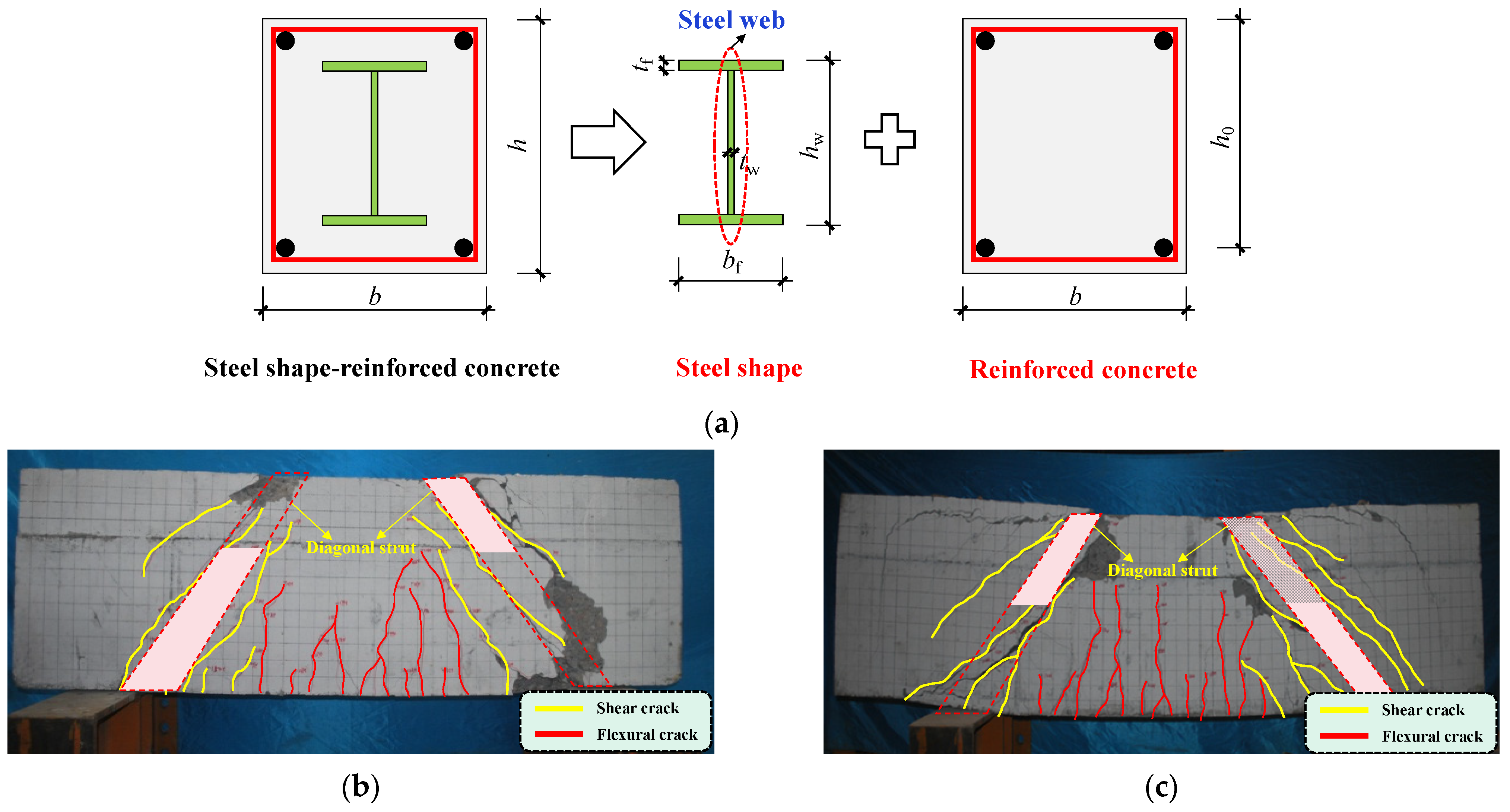
As shown in Figure 1a, steel shape-reinforced concrete (SRC), in which a steel profile (e.g., H-shaped steel, steel plate, or steel box) is encased in an R.C. section, is widely applied as transfer elements or columns in high-rise buildings. As an essential configuration of steel-concrete composite members, the local buckling of bare steel can be eliminated by introducing outer concrete encasement; meanwhile, compared with traditional R.C. members, the energy dissipation capacity can be enhanced due to the existence of an inner steel profile [1,2,3]. Until now, many countries have launched design guidelines for SRC members/structures [4,5,6], and in the ultimate state design, predicting the load-carrying capacities (bending, shear, and torsion) is essential to preventing structural elements from failure.

Figure 1.
(a) Steel shape-reinforced concrete beams; (b) Shear failure mode of R.C. beam; (c) Shear failure mode of SRC beam.
Unlike the flexural strength predictions based on simple plane section assumptions, the shear strength evaluation of steel-concrete composite members (including SRC) is more complex due to the so-called “composite action” between the steel profile and adjacent concrete. Under flexural action, the composite action exists on the plane section, namely that the normal strains of concrete, rebar, and steel shape along the sectional height must follow a linear distribution, and the strain field and the constitutive law can easily obtain the corresponding stress distribution. In this case, the steel and concrete can be merged into a composite cross-section, and both the steel and concrete are in compression above the neutral axis and in tension below the neutral axis. However, under shear action, the composite action should exist on the vertical section (following the shear stress flow), and in this case, the R.C. part and the steel profile behave in parallel, and the stress among these two parts cannot be unified due to the different failure modes. Under applied shear, the behavior of R.C. is governed by the diagonal cracking due to the diagonal directions of the principal stresses and the weaker tensile strength, whereas the stress within the steel profile follows the yielding criterion. Therefore, the R.C. and steel profiles of SRC members can be regarded as two nonlinear shear springs in parallel, and the shear contributions are related to their stiffness [7].
The strength predictions for SRC members in current design codes follow the same principles as the aforementioned mechanical behavior, namely, the plane section assumption in flexural strength predictions and the strength superposition in shear strength predictions. Nevertheless, the traditional strength superposition was challenged by the experimental results of Chen et al. [8]. In their experiments, twelve specimens, including two concrete beams and ten SRC beams, were designed to explore the effect of steel shape on static behavior. Among these SRC specimens, the geometric dimensions (width and height of the cross-section) and material properties were all the same, and the cross-sectional depth of the steel shape was different under the condition of the same cross-sectional area (the web thickness varied), namely that the nominal shear strengths of these steel shapes were almost the same. According to the traditional strength superposition, the overall shear resistance of SRC beams is the sum of the contributions of R.C. and steel profile, which can be calculated following the shear equations of R.C. and bare steel. If so, the peak load of the SRC beams in Ref. [8] should be comparable; nevertheless, the maximum load difference between these specimens was up to 50%, indicating that the simple strength superposition is questionable and there is interaction between R.C. and steel shape during the loading process. As shown in Figure 1b,c, the explicit failure patterns of traditional R.C. and SRC are almost the same, namely, the crushing of the inclined concrete strut; meanwhile, the stress state and deflection of the encased steel cannot be observed and determined directly, making the shear resistance calculation of the steel profile complex. Therefore, the load-sharing mechanism is essential for SRC members.
With the aim of investigating the load-sharing mechanism, many researchers have established mechanics-based models. On the basis of the softened strut-and-tie (SST) model adopted for R.C. members [9], Lu [10] and Chen et al. [8] extended the SST model to SRC beams, and the steel shape was simplified as longitudinal or diagonal reinforcement. However, there was no direct experimental evidence to reveal the steel shape’s role, whereas F.E. results show that the steel web’s stress at both principal directions was striking, indicating that the steel web behaved in bi-directional rather than one-way reinforcement [11]. Deng et al. [12] put forward a modified direct strut-and-tie model (DSTM) for predicting the shear resistance of SRC beams. In their model, the steel web is simplified as stirrups or longitudinal rebar; however, unlike stirrups in R.C. members that contribute strength after concrete cracking, the continuous steel web can improve the rigidity and strength of the entire member from the beginning of the loading process. Zeng et al. [13] and Ke et al. [14] adopted the modified compression field theory (MCFT) in SRC members [15], in which the shear contribution of the steel profile is obtained by multiplying the shear strain by the shear modulus. However, its rationality is doubtful because the steel profile is not in pure shear during the loading process. To conclude, current shear models for SRC beams are deduced from those of R.C. members, and the encased steel shape is basically simplified as discrete one-way steel reinforcement. It seems reasonable because the explicit failure patterns between SRC and R.C. members are similar, namely, the development of inclined concrete cracks; however, the effect of the encased steel shape on the overall shear strength needs further investigation because of the two-way property and the coupled stress distribution.
To further explore the shear mechanism of SRC members, an innovative approach is proposed to evaluate the shear resistance mechanism of SRC girders in this paper. The R.C. part is simulated using a simplified composite truss analogy, while the steel profile’s shear contribution is obtained based on the yielding criterion with strain compatibility. Finally, the accuracy of the established model is validated by comparing it with previously published models and available experimental test data in the literature.
2. Proposed Model
2.1. Model Description
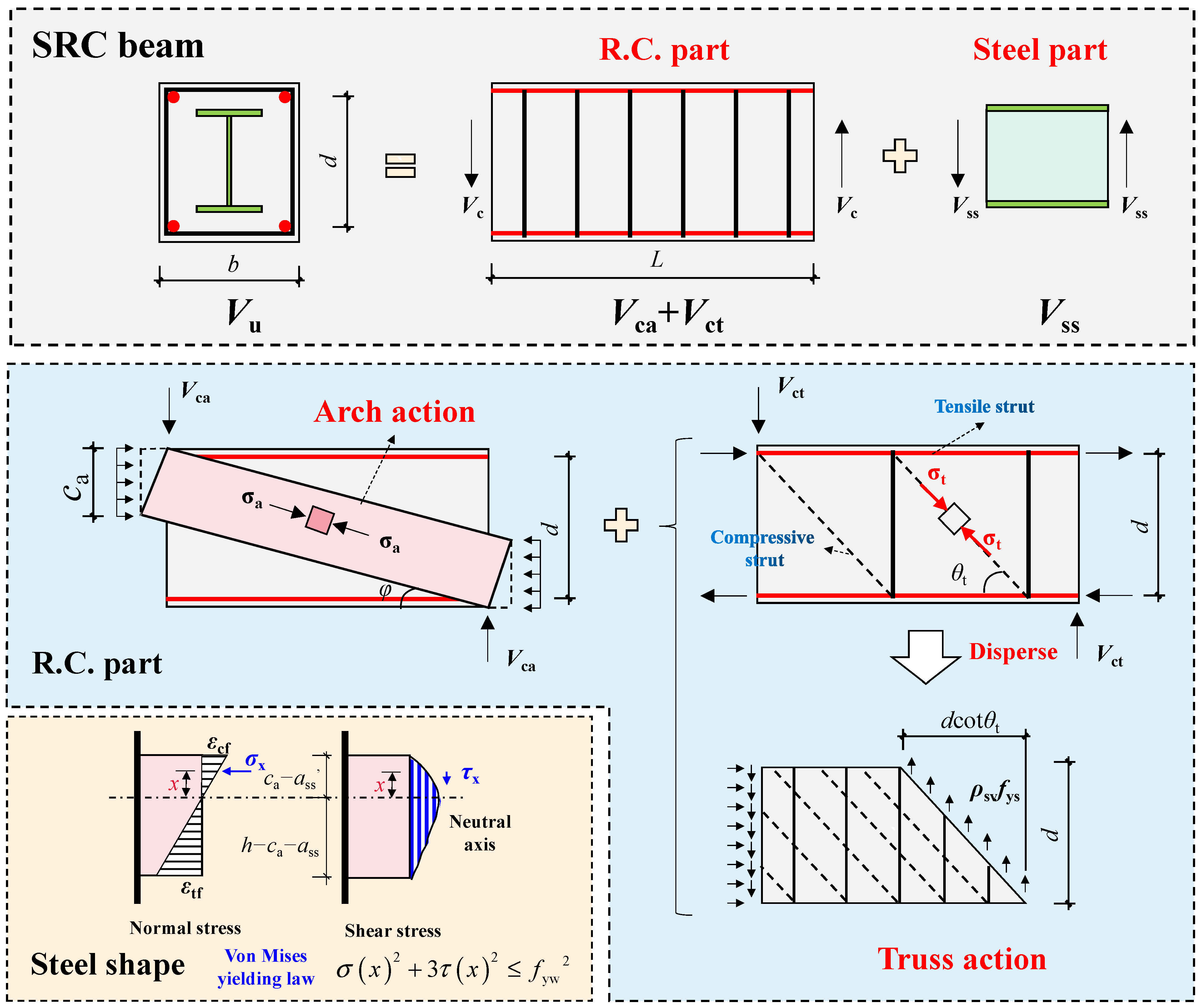
As illustrated in Figure 2, the proposed model is composed of two major parts: (1) The composite truss consists of longitudinal and transverse reinforcements, concrete, and two steel flanges; (2) the vertical steel web. The total shear strength Vu is the sum of the shear capacities of these two mechanisms: the composite truss Vc and the vertical web Vss. As mentioned before, the crack and failure patterns of SRC beams are similar to those of R.C. beams, indicating that the composite truss can reach the corresponding shear strength at the maximum load. In contrast, the shear contribution of the vertical steel web can be determined following deformation compatibility to show the steel-concrete interaction.
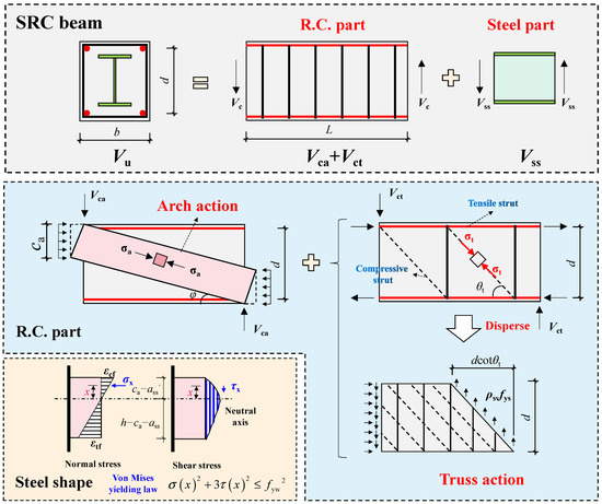
Figure 2.
Model configuration (Vct and Vca are the shear resistance of the truss arch and arch action).
In addition, in the proposed model, the top and bottom flanges and the vertical web of H-shaped steel work through different anti-shear mechanisms. The steel flanges play roles in the composite truss to reinforce the diagonal strut, and the steel web directly carries the vertical shear according to available test results [8,11]. However, these components operate integrally in terms of strain compatibility. In this case, strain compatibility can be employed to ensure coherence between the vertical web and two flanges and to assess their contact.
2.2. Truss-Arch Modeling of Composite Truss
The shear behavior of the composite truss is modeled using the truss-arch model, which was proposed by Ichinose [16] and has been applied in the Architectural Institute of Japan (AIJ) Design Guidelines. According to existing knowledge, the shear behavior of R.C. members is strongly affected by the shear span-to-depth ratio λ [17]. λ can be obtained by dividing the shear span length by the cross-sectional height, and the shear span is the distance between the loading point and the adjacent support. When λ is low, the arch action, which follows the path connecting the loading point and the support, governs the shear behavior. When λ is high, the truss action is dominant. The truss-arch model can capture the characteristics mentioned above; therefore, it has been widely applied in the shear strength/stiffness predictions of R.C. members. The shear resistance of the truss-arch model is the sum of the truss action Vct and the arch action Vca. As indicated in Figure 2, Vct can be expressed as:
where Vct is the truss action’s shear contribution; b is the cross-sectional width; d is the distance from the center of the compressive rebar to that of the tensile rebar; ρsv is the ratio of the transverse reinforcements; fys is the yield strength of the transverse reinforcements; θt is the angle between the horizontal axis and the compressive strut; Asv is the cross-sectional area of the stirrup ribs; s is the stirrup spacing.
θt can be obtained following the constant angle truss model (CATM) proposed by Kim and Mander [18]. As a mechanics-based model, CATM is deduced based on the principle of minimum potential energy, as follows:
where ρsl is the ratio of the tensile reinforcement, including longitudinal rebar and steel flange at the tensile section; Av is the shear area, Av = bd; Ag is the gross area of the entire cross-section.
As indicated in Figure 2, in the truss-arch model, the arch action can be simulated as a direct strut connecting the loading point and the adjacent support. It appears that the diagonal concrete serves as a compressive strut in truss and arch actions, and the compressive stresses of the diagonal concrete in truss and arch actions can be σt and σa, respectively. If the value σt + σa exceeds the effective strength of the diagonal concrete, the composite truss fails. In fact, the σt and σa are not in the same direction, and the shear contributions of the truss and arch models should follow the corresponding stiffness. Nevertheless, most existing research assumed that σt and σa worked in the same direction and applied plastic analysis for simplification, which has been proven acceptable for engineering purposes [19]. In this case, the shear contribution of the arch action Vca can be expressed as follows:
where σt is the compressive stress of the diagonal concrete in the truss action, which can be obtained by the free-body diagram of the applied truss; ca is the cross-sectional depth of the arch, which equals the cross-sectional depth of the neutral axis at the loading section; β is the softened factor of the cracked concrete; φ is the inclination of the arch, φ = (h − ca)/L; L is the length of the shear span; h is the height of the cross-section.
According to existing knowledge, when concrete experiences shear force, the effective compressive strength of concrete fce varies according to the transverse tensile strain εt. In this case, the compressive strength of concrete will be “softened” with the increase in the loading process [15]. Theoretically, the concrete softened should be evaluated using softening equations; nevertheless, obtaining εt at a certain load level is complex, and iterative analysis must be included to obtain εt accurately. In the proposed model, the concrete softening is evaluated by the equations in ACI 318 [17], in which the effect on concrete strength can be expressed as 0.85βfc and the softened factor β can be determined as:
where Asi is the total area of distributed reinforcement at spacing si in the i-th direction of reinforcements crossing a strut at an angle αi to the axis of a strut, whose detailed meaning can be found in provision R23.5.3 in ACI 318 [17].
The cross-sectional depth of the arch ca can be obtained based on the elastic analysis [9]:
where n = Es/Ec; Es and Ec are the moduli of elasticity of steel and concrete, respectively; ρsl′ is the ratio of the compressive reinforcement, including the steel flange and longitudinal rebar at the compressive section.
2.3. Stress Decomposition of Steel Shape
As mentioned before, under applied shear force, the encased steel of SRC beams works through two shear mechanisms. For example, the two flanges of H-shaped steel can be regarded as longitudinal reinforcement in the composite truss, and the vertical web is directly subjected to the applied shear force. In the vertical steel web, the normal and shear stresses exist simultaneously; therefore, it is essential to decouple the shear stress along the web section to determine its shear contribution.
According to existing experimental results, the steel web could be fully yielded; in this case, the normal and shear stresses at web elements must obey the yielding law [11]. As shown in Figure 2, the yielding criterion proposed by von Mises is applied here, as expressed in Equation (8).
where fyw is the steel web’s yield strength.
It is essential to mention that the concrete encasement transmitted the applied load to the encased steel, unlike bare steel members. However, there is currently a lack of available test results and reliable finite element evidence regarding the mechanisms of load sharing. As a result, determining the stress distribution only according to the shear force and bending moment at a specific section does not have a definitive solution. Therefore, it is necessary to conduct stress decomposition of the steel web while making reasonable assumptions [20]. Available test results showed a strong bond between the concrete encasement and the steel profile when sufficient concrete cover was present [11]. Existing test results indicated that the R.C. section and the steel web displayed compatible behavior according to the strain monitor, conforming to the assumption of the plane section [11].
Therefore, the normal stress of the vertical web can be easily determined by σx = Esεx, and the corresponding shear stress τx can be deduced by the yielding criterion (Equation (8)). The steel web’s shear contribution Vss can be obtained by integrating τx along the cross-section, as follows:
where Vsa is the shear contribution above the neutral axis; Vsb is the shear contribution below the neutral axis; ca is the sectional depth of the compression area at the loading section, which can be obtained following Equation (7); ass′ and ass are the thickness of the concrete cover of the steel flanges in compression and tension; tw is the steel web’s thickness; εcf is the strain of the steel flange in compression; εtf is the strain of the steel flange in compression; εc is the strain at the extremely compressive fiber at the loading section, εc = (1 − 0.44λ)εc0 [21,22]; εc0 is the peak compressive strain of concrete.
It is difficult to find accurate solutions for Vsa and Vsb; therefore, using a suitable numerical integration method is advisable. In this case, the two-point Gauss truss model is utilized, and Equations (10) and (11) can be rewritten as follows:
where ωi and ti are the numerical weight factor and the normalized coordinate of the ith numerical point. In the two-point Gauss truss model, t1 = −0.55735 and t2 = 0.55735; ω1 = ω2 = 1.0.
2.4. Calculation Process
The calculation process can be found below:
- (1)
- Input the geometric dimensions, reinforcement details, and the properties of concrete and steel;
- (2)
- Calculate the shear resistance of the truss and arch actions Vct + Vca by Equations (1)–(7);
- (3)
- Calculate the shear resistance of the vertical steel web Vss by Equations (9)–(15);
- (4)
- Calculate the overall shear strength of SRC beams by Vct + Vca + Vss.
3. Results and Discussions
3.1. Test Database
In this section, a database consisting of 50 SRC beams is established to verify the proposed model, and all these specimens were reported to fail in typical shear [8,10,12,13,23]. The test samples in the database exhibit a range of properties, as follows:
- (1)
- The compressive strength of concrete varies from 23.3 MPa to 46.6 MPa;
- (2)
- The yield strength of steel web varies from 265 MPa to 332 MPa;
- (3)
- The steel shape ratio varies from 2.16% to 6.62%;
- (4)
- The shear span-to-depth ratio varies from 0.84 to 2.00;
- (5)
- The width of the cross-section varies from 150 mm to 450 mm;
- (6)
- The height of the cross-section varies from 240 mm to 650 mm;
- (7)
- The stirrup ratio varies from 0.00% to 0.52%.
Table 1 presents a summary of the references utilized for conducting the comparison.

Table 1.
Test database.
3.2. Comparison between Tested and Calculated Results
A comparison was made between the test results and the shear strengths calculated using the proposed model, as shown in Table 1 and Figure 3. The results demonstrate that the established model can predict the shear strength of SRC girders accurately. The average ratio of calculated to tested shear strength (AVG) is 0.98, and its coefficient of variation (CoV) is 0.10. In order to verify the proposed steel-concrete interaction, this section compares the predicted results using the proposed model and the traditional strength superposition. The strength superposition, which is basically applied in code-based shear equations, means Vu = Vct + Vca + Vss,p, in which Vct + Vca can be determined by the proposed truss-arch analogy and Vss,p is the steel web’s shear resistance using plastic analysis (Vss,p = 0.6fywtwhw, where hw is the steel web’s cross-sectional height). Based on strength superposition, the average ratio of predicted results to tested results was found to be 1.44 with a coefficient of variation of 0.12, indicating that the proposed model can achieve higher precision. This comparison highlights the questionable validity of the strength superposition assumption, specifically when considering the steel web as plastic under pure shear. Moreover, the overestimated shear strengths indicate that the resistance along the vertical direction of the steel web is reduced due to the normal stress induced by bending. Therefore, the proposed steel-concrete interaction model, which incorporates strain compatibility, accurately predicts Vss (the shear strength of the steel web).
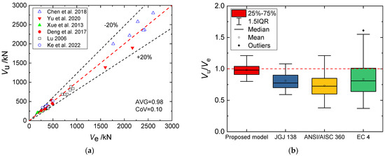
Figure 3.
(a) Comparison between tested and calculated results [8,10,11,12,13,23]; (b) Comparison between different shear formulas.
As depicted in Figure 3, a comparative analysis was conducted between the test results and the shear formulas specified in the design guidelines (without coefficients), and the corresponding shear equations can be referred to in Table 2. The calculation results show that the JGJ 138 equation [4] had an AVG of 0.81 and a CoV of 0.18, the ANSI/AISC 360 equation [5] had values of 0.73 and 0.27, and the Eurocode 4 equation [6] had values of 0.74 and 0.31. The comparison indicates that the shear equations based on design codes exhibit a significant level of strength underestimation and a wide scattering of results. While prioritizing higher reliability in the shear strength prediction of SRC members may appear rational due to the brittle failure property, it is crucial to address the issue of excessively underestimated strength predictions. This discrepancy not only results in a significant waste of construction materials but also contradicts the goals of a sustainable environment. Therefore, there is an urgent need to conduct a comprehensive investigation into the shear mechanisms of the SRC beam. As mentioned above, shear equations/models of traditional R.C. members can be employed to evaluate the shear contribution of the concrete encasement; some emerging tool, e.g., deep learning, needs to be involved in the future to predict the shear strength of SRC members [24].
Table 2.
Shear formulas in current design codes.
In addition, there is another shear model proposed by the authors for predicting the shear strength of SRC models [25]; however, these two models focus on different aspects of shear behavior; this model aims to decouple the shear contributions of the R.C. and encased steel profile, while the other model aims to address the relationship between the shear stiffness of these two parts, which can be better applied in CES beams with high-strength steel. Theoretically, the proposed model should be further refined to adapt to high-strength steel profiles, namely that the steel profile is not yielded at the maximum load; however, the proposed shear model is feasible for current engineering practices. A combination of the two aforementioned models will be established in the future.
4. Conclusions
An innovative shear strength model for SRC girders is put forward in this paper. The principal attributes of the proposed model can be summarized as follows:
- (1)
- Multiple shear mechanisms, which consist of a vertical steel web and a composite truss, exist to resist the applied shear load. In the proposed model, the shear strength of the composite truss is evaluated using the traditional truss-arch model, and a stress decomposition based on von Mises yielding criterion is conducted within the steel shape to decouple its shear contribution. Finally, the total shear strength can be determined by superimposing the shear contributions of these two mechanisms;
- (2)
- Through verification with 50 available test results for SRC beams, the proposed model demonstrated its superiority. The predictions generated by the proposed model (with an AVG of 0.98 and a CoV of 0.10) exhibited significantly better agreement with the test results when compared with existing shear equations. For instance, the JGJ 138 equation had an AVG of 0.81 and a CoV of 0.18, the ANSI/AISC 360 equation had values of 0.73 and 0.27, and the Eurocode 4 equation had values of 0.74 and 0.31, indicating that the established model can effectively and reliably predict the shear strength of SRC beams.
Author Contributions
Conceptualization, Y.X.; methodology, Y.X.; validation, Y.X., Y.L. and Y.Y.; formal analysis, X.Z.; investigation, X.Z.; data curation, Y.L. and Y.Y.; writing—original draft preparation, X.Z.; writing—review and editing, Y.X.; visualization, Y.L.; supervision, Y.X.; project administration, Y.X.; funding acquisition, Y.X. All authors have read and agreed to the published version of the manuscript.
Funding
The authors express their sincere appreciation for the financial support received from the Key R&D Program of Shaanxi Province (2022SF-433).
Data Availability Statement
The data presented in this study are available upon request from the corresponding author.
Conflicts of Interest
The authors declare no conflict of interest.
References
- Lai, B.L.; Zhang, M.Y.; Zheng, X.F.; Chen, Z.P.; Zheng, Y.Y. Experimental Study on the Axial Compressive Behaviour of Steel Reinforced Concrete Composite Columns with Stay-in-Place ECC Jacket. J. Build. Eng. 2023, 68, 106174. [Google Scholar] [CrossRef]
- Lai, B.L.; Yang, L.; Xiong, M.X. Numerical Simulation and Data-Driven Analysis on the Flexural Performance of Steel Reinforced Concrete Composite Members. Eng. Struct. 2021, 247, 113200. [Google Scholar] [CrossRef]
- Lai, B.L.; Tan, W.K.; Feng, Q.T.; Venkateshwaran, A. Numerical Parametric study on the Uniaxial and Biaxial Compressive Behavior of H-shaped Steel Reinforced Concrete Composite Beam-Columns. Adv. Struct. Eng. 2022, 25, 2641–2661. [Google Scholar] [CrossRef]
- JGJ 138-2016; Code for Design of Composite Structures. China Architecture & Building Press: Beijing, China, 2016.
- ANSI/AISC 360-16; Specification for Structural Steel Buildings. American Institute of Steel Construction: Chicago, IL, USA, 2016.
- BS EN 1994-1-1:2004; Eurocode 4: Design of Composite Steel and Concrete Structures—Part 1-1: General Rules and Rules for Buildings. European Committee for Standardization: Brussels, Belgium, 2004.
- Xue, Y.; Shang, C.; Yang, Y.; Yu, Y. Prediction of Lateral Load-Displacement Curve of Concrete-Encased Steel Short Columns Under Shear Failure. Eng. Struct. 2022, 262, 114375. [Google Scholar] [CrossRef]
- Chen, C.C.; Lin, K.T.; Chen, Y.J. Behavior and Shear Strength of Steel Shape Reinforced Concrete Deep Beams. Eng. Struct. 2018, 175, 425–435. [Google Scholar] [CrossRef]
- Hwang, S.J.; Lee, H.J. Strength Prediction for Discontinuity Regions by Softened Strut-and-Tie model. J. Struct. Eng. 2002, 128, 1519–1526. [Google Scholar] [CrossRef]
- Lu, W.Y. Shear Strength Prediction for Steel Reinforced Concrete Deep Beams. J. Constr. Steel Res. 2006, 62, 933–942. [Google Scholar] [CrossRef]
- Yu, Y.; Yang, Y.; Xue, Y.; Liu, Y. Shear Behavior and Shear Capacity Prediction of Precast Concrete-Encased Steel Beams. Steel Compos. Struct. 2020, 36, 261–272. [Google Scholar]
- Deng, M.; Ma, F.; Li, B.; Liang, X. Analysis on Shear Capacity of SRC Deep Beams based on Modified Strut-and-Tie Model. Eng. Mech. 2017, 34, 95–103. [Google Scholar]
- Ke, X.J.; Tang, Z.K.; Yang, C.H. Shear Bearing Capacity of Steel-Reinforced Recycled Aggregate Concrete Short Beams based on Modified Compression Field Theory. Structures 2022, 45, 645–658. [Google Scholar] [CrossRef]
- Chen, B.Q.; Zeng, L.; Liu, C.J.; Mo, J. Study on Shear Behavior and Bearing Capacity of Steel Reinforced Concrete Deep Beams. Eng. Mech. 2022, 39, 215–224. [Google Scholar]
- Bentz, E.C.; Vecchio, F.J.; Collins, M.P. Simplified Modified Compression Field Theory for Calculating Shear Strength of Reinforced Concrete Elements. ACI. Struct. J. 2006, 103, 614–624. [Google Scholar]
- Ichinose, T. A Shear Design Equation for Ductile R/C Members. Earthq. Eng. Struct. D 1992, 21, 197–214. [Google Scholar] [CrossRef]
- ACI 318-14; Building Code Requirements for Structural Concrete. American Concrete Institute: Farmington Hills, MI, USA, 2014.
- Kim, J.H.; Mander, J.B. Influence of Transverse Reinforcement on Elastic Shear Stiffness of Cracked Concrete Elements. Eng. Struct. 2007, 29, 1798–1807. [Google Scholar] [CrossRef]
- Pan, Z.; Li, B. Truss-Arch Model for Shear Strength of Shear-Critical Reinforced Concrete Columns. J. Struct. Eng. 2013, 139, 548–560. [Google Scholar]
- Horne, M.R. Plastic Theory of Structures; Pergamon Press: Surrey, UK, 1979. [Google Scholar]
- Choi, K.K.; Park, H.G.; Wight, J.K. Unified Shear Strength Model for Reinforced Concrete Beams-Part I: Development. ACI Struct. J. 2007, 104, 142–152. [Google Scholar]
- Choi, K.K.; Park, H.G. Unified Shear Strength Model for Reinforced Concrete Beams-Part II: Verification and Simplified Method. ACI Struct. J. 2007, 104, 153–161. [Google Scholar]
- Xue, J.; Wang, X.; Ma, H.; Lin, J.; Chen, Z. Experimental Study on Shear Performance of Steel Reinforced Recycled Aggregate Concrete Beams. Build. Struct. 2013, 43, 69–72. [Google Scholar]
- Barkhordari, M.S.; Feng, D.C.; Tehranizadeh, M. Efficiency of Hybrid Algorithms for Estimating the Shear Strength of Deep Reinforced Concrete Beams. Period. Polytech. Civ. Eng. 2022, 66, 398–410. [Google Scholar] [CrossRef]
- Xue, Y.; Yang, Y.; Yu, Y. Shear Strength Model for Steel Reinforced Concrete Composite Members: Short Columns and Deep Beams. Eng. Struct. 2020, 216, 110748. [Google Scholar] [CrossRef]

Disclaimer/Publisher’s Note: The statements, opinions and data contained in all publications are solely those of the individual author(s) and contributor(s) and not of MDPI and/or the editor(s). MDPI and/or the editor(s) disclaim responsibility for any injury to people or property resulting from any ideas, methods, instructions or products referred to in the content. |
© 2023 by the authors. Licensee MDPI, Basel, Switzerland. This article is an open access article distributed under the terms and conditions of the Creative Commons Attribution (CC BY) license (https://creativecommons.org/licenses/by/4.0/).