1. Introduction
Energy consumption in the building sector accounts for more than one-third of the total energy consumption worldwide [
1,
2], where a significant portion of the total energy consumed in the building sector is operational energy used for space heating and cooling [
3]. More specifically, in the United States, the thermal exchange through opaque envelopes provides more than 7% of primary energy consumption [
4]. Conventionally, the thermal performance of building envelopes is often characterized by their thermal resistance (i.e., R-value) [
5,
6]. Currently, R-value-based prescriptions are used by building codes (e.g., ASHRAE 90.1, ASHRAE 90.2, and IECC) to guide building envelope design and improve the energy efficiency of buildings. Therefore, it is very crucial for manufacturers to construct building envelopes that have good thermal performance to minimize buildings’ energy consumption.
To accurately measure the thermal performance of building envelopes before making them available in the market, construction companies and manufacturers send specimens from their designed building envelopes to accredited laboratories to conduct required experiments. However, performing thermal performance tests in accordance with the standards by accredited laboratories can cost up to USD 20,000 per sample, and many laboratories have waiting lists of up to seven months [
7]. This is a significant expenditure for start-up and small-scale business companies in the construction industry that have small to mid-revenue [
7]. Accordingly, this study proposed the design, construction, and testing of a smaller-scale and portable environmental chamber to measure the thermal performance (i.e., R-value) of building envelopes at extreme climate conditions varying from −16 °C (3 °F) to 65 °C (150 °F) following the ASTM C1363 and ISO 8990 standards [
8,
9]. The advantages of a portable environmental chamber includes: (i) flexibility to conduct experiments in a variety of locations and at different ambient temperatures; (ii) cost saving since a permanent environmental chamber can be extremely expensive, and thus, a portable chamber can be constructed using less expensive materials and can be reused in different locations, saving on the cost of building multiple chambers; and (iii) ease of storage, as a portable environmental chamber can be disassembled and reassembled again when saving space is needed.
Generally, different methods are used to measure the thermal properties of building envelopes in controlled environments (e.g., a laboratory). In the case of one-dimensional heat flow, the most common methods used to measure the thermal properties are the guarded hot plate [
10] and the heat flow meter [
11]. However, using these methods has some limitations, as they are only capable of testing homogeneous building materials such as concrete, plywood, brick, and glass [
12]. In the case of large-scale and nonhomogeneous building envelopes, environmental chambers are used to determine the thermal properties of different building components at controlled environmental conditions (see ASTM C1363 [
8]). The environmental chamber is used to measure the thermal performance of nonhomogeneous building components with multi-dimensional heat flows.
An environmental chamber is typically designed to have either two or all three of the main components of [
8]: (1) a climatic chamber that simulates indoor climate conditions; (2) a metering chamber that simulates outdoor weather conditions; and (3) a guard chamber that is added around the metering chamber to minimize flanking loss at the boundaries and through the walls of the metering chamber. The ASTM C1363 [
8] standard is categorized, by measuring the thermal performance of building envelopes, into two main designs: guarded environmental chamber and calibrated environmental chamber. The guarded environmental chamber consists of all three design components (climatic, metering, and guard chambers), and it is considered to be a self-masking design since the guard chamber surrounds and protects the metering chamber from any source of heat leakage throughout the duration of the experiments. On the other side, the calibrated environmental chamber consists of two main design components (climatic and metering chambers), where this design uses ambient temperature around the metering chamber as a guard. In this study, the guarded environmental chamber was constructed and used to conduct experiments to measure the thermal performance of wall panels at hot climate conditions, while a calibrated environmental chamber was constructed and used to perform thermal performance measurements of prefabricated wall panels at cold climate conditions. Therefore, the guarded environmental chamber is referred to as the heating chamber, and the calibrated environmental chamber is referred to as the cooling chamber throughout this paper. The two designs help in accurately measuring the experimental thermal performance of building envelopes in controlled environmental conditions.
This study provides researchers and building material testing companies with the opportunity to test multiple building envelopes at a relatively low cost and in a shorter waiting duration (i.e., no long waiting time to test building envelopes). The use of the environmental chamber also allows for the accurate evaluation of innovative designs and the refinement of wall specimen prototypes for manufactured building materials.
2. Background
Many studies have investigated the thermal performance (i.e., R-value, U-value) of various building envelopes using environmental chambers [
7,
13,
14,
15,
16,
17,
18,
19,
20,
21,
22,
23,
24,
25,
26,
27,
28,
29,
30]. Despite the significant contribution of these studies in measuring the thermal performance of building envelopes using environmental chambers, there are still some limitations, including: (1) the proposed methodology for constructing the environmental chamber is too expensive; (2) the environmental chamber does not meet the minimum size requirements of the ASTM C1363 and ISO 8990 standards; (3) the environmental chamber size design is too bulky and not portable; and/or (4) the environmental chamber cannot maintain the steady-state temperature during the experiment within ±1 °C to meet the requirement of the ASTM C1363 standard.
Seitz and MacDougall [
7] and Seitz et al. [
21] constructed an affordable environmental chamber of 1.37 m (4.5 ft) × 1.2 m (3.9 ft) that meets the minimum metering chamber opening area of 1 m
2 (40 inch × 40 inch) required by ISO 8990-96 as well as meets the ASTM C1363-19 standard of having the minimum number of temperature sensors installed (minimum of five thermocouples per unit of wall area). The constructed environmental chamber was capable of conducting experiments in a temperature range of −24 °C (−11 °F) to 21 °C (70 °F). However, the reading accuracy at the steady-state temperature can vary by ±3 °C, which does not meet the minimum accuracy required for thermal performance measurements required by ASTM C1363-19.
Mero [
18] also constructed an environmental chamber of 1.23 m (48½ inch) tall, 1.57 m (62 inch) long, and 0.53 m (21 inch) deep. The environmental chamber was capable of measuring thermal performance of various on-site wall panels in a temperature range of 5 °C (41 °F) to 46 °C (120 °F). However, there was an inconsistency in the installed thermocouples readings and significant air leakages during the experiment, and the installed chiller was not able to conduct experiments in subzero weather conditions. These gaps resulted in not meeting the minimum requirements of precision in the experiments required by ASTM C1363-19 and ISO 8990-19 standards.
Chowdhury and Neogi [
14] built a guarded environmental chamber to measure the thermal performance of a masonry wall and reinforced concrete member used in tropical climate conditions. The chamber was designed to conduct experiments in a temperature range of −20 °C (−4 °F) to 50 °C (122 °F). Although the results indicated the accuracy of the constructed environmental chamber in measuring the thermal performance of building envelopes, the environmental chamber is not portable, and the chamber was not capable of testing the building envelopes in extremely hot weather conditions of more than 50 °C (122 °F).
Peters et al. [
19] constructed a small size environmental chamber of 0.52 m (20.5 inch) tall, 0.29 m (11.25 inch) long, and 0.2 m (8 inch) deep to measure the thermal performance of three-dimensional printed bricks. The chamber was capable of testing the brick specimen under a temperature of 60 °C (140 °F). However, this chamber was not able to meet the minimum size required by the ISO 8990-96 standard. Additionally, the R-value results were not accurate due to a significant amount of heat loss from the corners and edges of the chamber. Further, measuring heat input by counting controller switching frequency and the relatively small size of the environmental chamber were additional factors that contributed to errors. Additionally, the absence of heat flux sensors hampered the precision of their experiments.
Ghosha et al. [
15] constructed an environmental chamber to measure various building envelopes under different software-based temperature control strategies. The chamber was able to conduct thermal performance experiments in a temperature range of 0 °C (32 °F) to 40 °C (104 °F). The results revealed variations in the thermocouple temperature readings and the thermal performance results, which were attributed to the utilization of an on-off mechanism to regulate temperature due to the lack of control over the heating and cooling systems. Additionally, the experiment’s duration of 3 h was inadequate to establish the accuracy of their findings.
Smith [
22] developed a modified version of the guarded environmental chamber specified in the ASTM C1363 standard of 0.83 m (32.5 inch) tall and 0.83 m (32.5 inch) long for measuring the thermal performance of non-homogenous building envelopes. The chamber was able to conduct experiments in a temperature range of −5 °C (23 °F) to 60 °C (140 °F). It was also built to be portable to move it easily. However, the results indicated some fluctuations in the thermal performance results. Additionally, the size of the chamber was smaller than the minimum metering chamber opening area of 1 m
2 (40 inch × 40 inch) required by ISO 8990-96.
Boudreaux et al. [
13] used a full-sized off-site manufactured environmental chamber of 3 m (10 ft) tall × 2.4 m (8 ft) long, which met the ASTM C1363-19 full-size requirements. The environmental chamber could measure the thermal performance of various wall panels to simulate indoor and outdoor temperatures of 15.6 to 32.2 °C (60 to 90 °F) and −17.8 to 43.3 °C (0 to 110 °F), respectively, and 10 to 90% relative humidity. This chamber could also provide high accuracy in thermal performance measurement test results, meeting all the requirements of ASTM C1363-19 and ISO 8990-96 standards. However, such an environmental chamber can be extremely expensive (up to USD 300,000). Additionally, the environmental chamber was not portable. Similar to this, Lucchi et al. [
17] used a full-sized off-site manufactured environmental chamber of 3 m (10 ft) tall × 2.4 m (8 ft) long that was used to measure the thermal performance of inhomogeneous wall panels (e.g., masonry walls) in a temperature range of −40 °C (−40 °F) to 40 °C (104 °F). Similar to the study conducted by Boudreaux et al. [
13], the cost of the environmental chamber used in this study was high, and the environmental chamber was not portable.
3. Objective
The objective of this study was: (i) to design, construct, and calibrate an environmental chamber system for heating and cooling application based on the ASTM C1363-19 and BS EN ISO 8990-96 standards; and (ii) to design, set up, and calibrate a high-tech data acquisition (DAQ) system coupled with an environmental chamber system.
4. Methodology
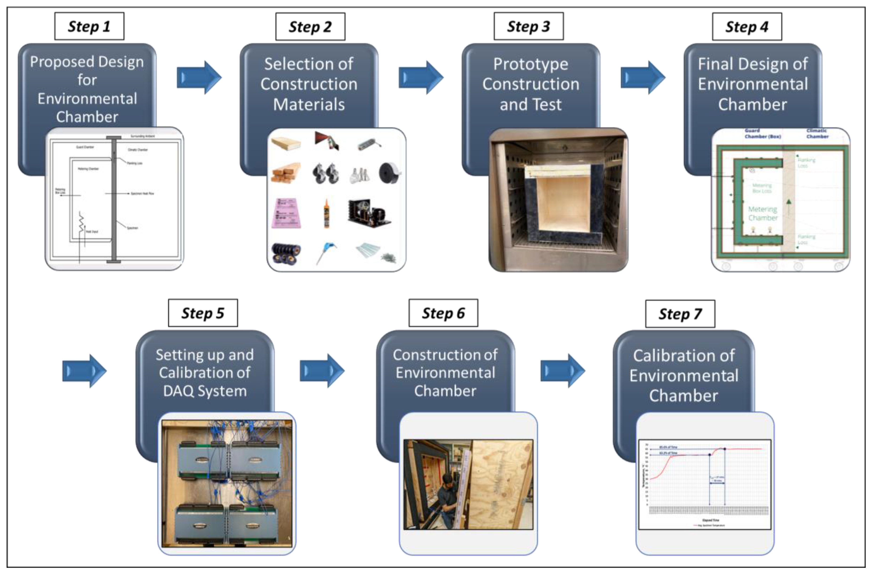
The process of constructing a portable and cost-effective environmental chamber can be outlined in seven primary steps (see
Figure 1), with a comprehensive explanation of each step given below.
Step 1 explains the method of designing an environmental chamber for both heating and cooling testing experiments following the ASTM C1363-19 and ISO 8990-96 standards. To meet the minimum requirements of these standards, the thermal performance of building envelopes was tested at a controlled temperature.
Step 2 determines the method of choosing construction materials to construct the environmental chamber after conducting a thorough review of the literature in the relevant field. The selection process considered both the practicality and strength of each material for use under prolonged exposure to extremely high and low temperatures, 65 °C (150 °F) and −20 °C (−4 °F), respectively, without any risk of possible combustion during the experiment.
Step 3 explains the method of constructing and testing a prototype of the proposed environmental chamber using the selected construction materials. This step helps to confirm and validate the effectiveness of the chosen construction materials when compacted together and used as one structure and exposed to extremely high and low temperatures.
Step 4 determines the final design of the environmental chamber in adherence to the standards set by ASTM C1363-19 and ISO 8990-96. The design was intended to achieve minimal heat loss for the duration of the experiment and to accommodate the maximum and minimum temperatures of 65 °C (150 °F) and −20 °C (−4 °F), respectively, that the environmental chamber would reach during the experiments.
Step 5 explains the method of setting up and calibrating high-tech data acquisition (DAQ) systems for the designed environmental chamber as well as installing humidity, temperature, and heat flux sensors on the DAQ system, along with their related software. The installed systems enable the users to visualize, read, and record relative humidity (RH%), temperatures, and heat flux readings in the environmental chamber.
Step 6 explains the construction of the environmental chamber capable of testing the thermal performance of various building envelopes in different weather conditions according to the guidelines and requirements of ASTM 1363 and ISO 8990 standards using the selected construction materials. The size of the constructed environmental chamber was selected based on the ISO 8990-96 standard and the wall panel sizes to make the environmental chamber portable to move from one location to another and to test the thermal performance of any building envelope in different climate conditions if needed.
Step 7 describes the process of calibrating the environmental chamber, which involves using the ASTM C1363-19 standard to check how well it measures the thermal performance of building envelopes in extreme hot and cold weather conditions. To determine accuracy and efficiency, the chamber must be tested using a characterization panel that is the same size as the actual wall panel specimen and has a known thickness, thermal conductivity, and R-value (more than 1 h ft2 °F/Btu or 0.176 m2 °C/W). The time constants are then identified by testing the panel for five consecutive cycles of experimental tests, as specified in ASTM C1363-19.
5. Implementation
The model developed for testing the experimental test analysis thermal performance of building envelopes was implemented in seven main steps. Each of these steps are implemented and explained in detail below.
5.1. Proposing Design for Environmental Chamber
In this step, the ASTM C1363-19 Standard Test Method for Thermal Performance of Building Materials and Envelope Assemblies by Means of a Hot Box Apparatus and ISO 8990-96 Thermal Insulation Determination of Steady-State Thermal Transmission Properties Calibrated and Guarded Hot Box standards were reviewed, which are two main standards related to conducting thermal performance measurements at steady-state weather conditions. The details and minimum requirements of the two standards were carefully reviewed to make sure that the proposed environmental chamber in this study can meet the minimum requirements of these standards. According to ASTM C1363-19 and ISO 8990-96 standards, an environmental chamber is generally designed to have three components known as the climatic chamber, metering chamber, and guard chamber. The climatic chamber imitates the weather conditions inside a building, while the metering chamber mimics the weather conditions outside. The guard chamber helps reduce the heat flow at the sides of the metering chamber [
8,
9]. Accordingly, the environmental chambers can be designed in one of two configurations: (1) a guarded environmental chamber (see
Figure 2a), and (2) a calibrated environmental chamber (see
Figure 2b). The guarded environmental chamber is a design that includes all three components of an environmental chamber, namely the climatic chamber, the metering chamber, and the guard chamber. It is a self-masking design, meaning that it has a controlled guard chamber surrounding the metering chamber (see
Figure 2a). On the other side, the calibrated environmental chamber utilizes the surrounding environment as a guard by incorporating highly resistant materials into the metering chamber to prevent heat from flowing through. This configuration consists of two main components to design the environmental chamber, namely the climatic chamber and the metering chamber (see
Figure 2b). Regardless of the selected configuration, the test specimen (i.e., building envelope) should be placed in between the climatic chamber and the metering/guard chambers to conduct the experiment (see
Figure 2a,b). In this study, a guarded environmental chamber was selected for the construction of the hot chamber (i.e., metering and guard chambers) of the environmental chamber, and a calibrated environmental chamber was selected for the construction of the cold chamber (i.e., metering chamber) of the environmental chamber. The climatic chamber was identical in the construction of both configurations, as shown in
Figure 2a,b. With that being said, the test specimens in this study were designed to be tested in both self-masked conditions, using the heating chamber, and masked conditions, using the cooling chamber, since the test wall panel specimens’ sizes were greater than or equal to the metering chamber opening sizes, respectively, following the ASTM C1363-19 standard.
Finally, the authors studied the minimum size required to construct a typical environmental chamber. The ISO 8990-96 standard indicated that the minimum size of the metering chamber opening must be 100 cm (40 inch) × 100 cm (40 inch), and there was no indication about the depth of the environmental chamber or the sizes of the climatic and guard chambers. Therefore, in this study, the minimum size requirements for the metering chamber were considered.
5.2. Selecting Construction Materials for the Environmental Chamber
The ASTM C1363-19 standard mandates that construction materials used in the construction of an environmental chamber apparatus must exhibit high thermal performance, meaning that they should have strong thermal insulating properties that enable them to retain heat better. In another words, the higher the thermal resistance of a material, the lower the thermal conductivity. Materials that have high thermal conductivity facilitate the quick transfer of heat, either by absorbing heat from a hotter material or by releasing heat to a colder material. In contrast, materials with low thermal conductivity function as thermal insulators, obstructing the movement of heat. However, the ASTM C1363-19 standard does not specify particular materials that should be used in the construction of an environmental chamber apparatus. Consequently, a thorough review of the relevant literature was conducted to select the construction materials [
7,
13,
14,
15,
16,
17,
18,
20,
21,
22,
23,
24,
25,
26,
27,
28,
29,
30]. Accordingly, four different construction materials were proposed: (1) 1.27 cm (½ inch) and 0.64 cm (¼ inch) plywood sheets, (2) PL premium construction adhesive, (3) 0.64 cm (¼ inch) Neoprene Gasket and Light Duty Blended EPDM Foam Strip, and (4) 2.54 cm (1 inch) Sika Foamular extruded polystyrene (XPS) insulation board and Sika Pro Select R-Matte Polyisocyanurate (RMAX) high thermal performance insulation board. In order to determine which materials would be best suited for constructing the environmental chamber, all the proposed construction materials were put to the test by the University of Illinois at Chicago (UIC) Built Environmental and Infrastructure Laboratory (BEI lab).
The first step involved testing XPS and RMAX foam insulation boards in an oven at extremely high temperatures. The purpose of this test was to evaluate the resistance and efficiency of each insulation board under high temperatures. During testing, the sample insulation boards were subjected to temperatures of 70 °C (158 °F), 100 °C (212 °F), and 150℃ (302 °F). At 70 °C, both the XPS and RMAX insulation boards showed no signs of impact and remained unchanged. At 100 °C (212 °F), the XPS began to shrink slightly, while the RMAX sample remained unaffected. At 150 °C (302 °F), the XPS board caught fire and completely melted, while the RMAX insulation board remained intact. Based on these results, the investigators opted to use the RMAX insulation board for constructing the prototype. In a second test, the efficiency of the neoprene gasket and Light Duty Blended EPDM Foam Strip were evaluated in the same manner. Again, the materials were exposed to temperatures of 70 °C (158 °F), 100 °C (212 °F), and 150 °C (302 °F). The results of the test showed that both strips remained unchanged and effective throughout the duration of the test; thus, they were chosen for the construction of the prototype.
5.3. Constructing and Testing a Prototype
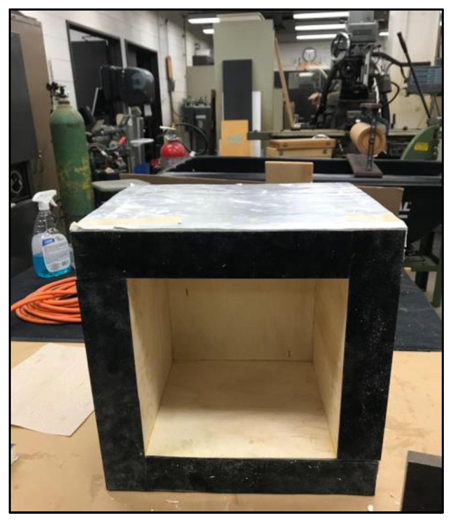
A prototype of an environmental chamber apparatus was built with inside dimensions of 25 cm × 25 cm × 25 cm (10 inch × 10 inch × 10 inch) to fit into a testing oven. The objective of conducting prototype testing was twofold: to evaluate the effectiveness of the selected construction materials when compressed under varying climatic conditions, and to finalize the materials that would be used for constructing the environmental chamber. To test the prototype, a methodology was employed that involved subjecting it to high temperatures for eight hours in a testing oven, followed by exposing it to outside weather conditions. It is worth noting that there is no standard duration for subjecting the prototype to high and low temperatures, and some studies did not even build or test a prototype (e.g., [
7,
21]). However, this is acceptable if the researchers have sufficient knowledge regarding the effectiveness of the materials being used for the environmental chamber’s construction, particularly since ASTM C1363-19 does not require such a process. Therefore, the prototype was made by sandwiching a 5 cm (2 inch) thick RMAX foam insulation board between two layers of 0.64 cm (¼ inch) thick plywood using PL construction adhesive, and the cross-section was sealed twice, one time with Neoprene Gasket and the second time with Light Duty Blended EPDM Foam Strip to see which strip worked best for the construction of the environmental chamber (see
Figure 3). The PL construction adhesive was selected in this study since it is three times stronger than ordinary adhesives, it is waterproof, it has a 24-h cure time compared to other adhesives that require a 48-h cure time, and it can be functional in a temperature range of 12 to 71 °C (10 to 160 °F). The prototype underwent a rigorous testing process to evaluate the effectiveness of the selected materials when combined and exposed to varying temperatures. Specifically, the prototype was subjected to a temperature of 150 °C (302 °F) for eight hours in a testing oven, followed by exposure to an outdoor temperature of approximately −10 °C (14 °F) for an entire day. This process was repeated twice to determine the impact of various climates on the materials’ functionality and efficiency when compacted together.
The results from the prototype testing indicated that the plywood and insulation board were functional, but the 0.64 cm (¼ inch) plywood bent; thus, 1.27 cm (½ inch) plywood was chosen for the final construction of the environmental chamber to avoid this issue. Moreover, the Neoprene Gasket failed after the prototype was exposed to a temperature of 150 °C (302 °F), while the Light Duty Blended EPDM Foam Strip remained functional and adhesive during the whole experiment. Consequently, the Light Duty Blended EPDM Foam Strip was chosen as the joint strip for the environmental chamber. The Light Duty Blended EPDM Foam Strip is made of rubber, has a temperature range of −23 to 93 °C (−10 to 200 °F), has a thickness tolerance, and has a highly adhesive sticky side that is capable of firmly adhering to surfaces. On the other side, although the Neoprene Gasket has an impressive operational temperature range of −40 to 204 °C (−40 to 400 °F), its rigid rubber composition lacks thickness tolerance and does not come with an adhesive backing to facilitate a secure attachment to the boundaries of the prototype and later on the environmental chamber. As a result, the Neoprene Gasket must be affixed to these surfaces using PL construction adhesive, which is not designed to withstand temperatures over 71 °C (160 °F). This in turn led to adhesive failure and a subsequent loss of attachment between the Neoprene Gasket and prototype boundaries.
5.4. Finalizing the Environmental Chamber Design
5.4.1. Heating Chamber Design
The heating chamber was designed in this study in accordance with ASTM C1363-19 and ISO 8990-96 standards. The authors chose the opening dimensions of the metering chamber to be 100 cm by 100 cm (40 inch by 40 inch) to meet the minimum requirements of UNI EN ISO 8990-96. The climatic chamber and guard chamber were made portable by selecting opening dimensions of 152 cm by 152 cm (5 ft by 5 ft), as shown in
Figure 4 and
Figure 5. Referring back to step 1 of this section, the ISO 8990-96 standard indicated that the minimum size of the metering chamber opening must be 100 cm × 100 cm (40 inch by 40 inch); however, there is no indication about the depth of the environmental chamber or the sizes of the climatic and guard chambers. Therefore, in the step, the metering chamber depth was selected to be 50 cm (19.5 inch) to fit in all the devices and sensors inside as well as to have the minimum number of insulation and plywood cuts. Additionally, the climatic chamber and guard chamber depth were selected to be 74 cm (29 inch) to have the minimum waste of insulation and plywood as well as to fit in the heating chamber in all standard door sizes available in the United States, as shown in
Figure 4. Additionally,
Figure 5 presents a schematic design of the heating chamber that was built using guarded environmental chamber configuration, including a metering chamber equipped with six 125-Watt BR40 Dimmable Incandescent 120-volt Heat Bulbs and a 12-volt air blower to distribute heat equally inside the heating chamber during experiments to achieve the desired temperature. The heating chamber was designed to conduct thermal performance measurement experiments for building envelopes up to 85 °C (185 °F) with the installed devices and sensors. The building envelopes were placed between the guard chamber and the climatic chamber to test their thermal performance. A Light Duty Blended EPDM Foam Strip was added all around the frame of the three components of the heating chamber (i.e., climatic, metering, and guard chambers) to minimize losses at the intersection points.
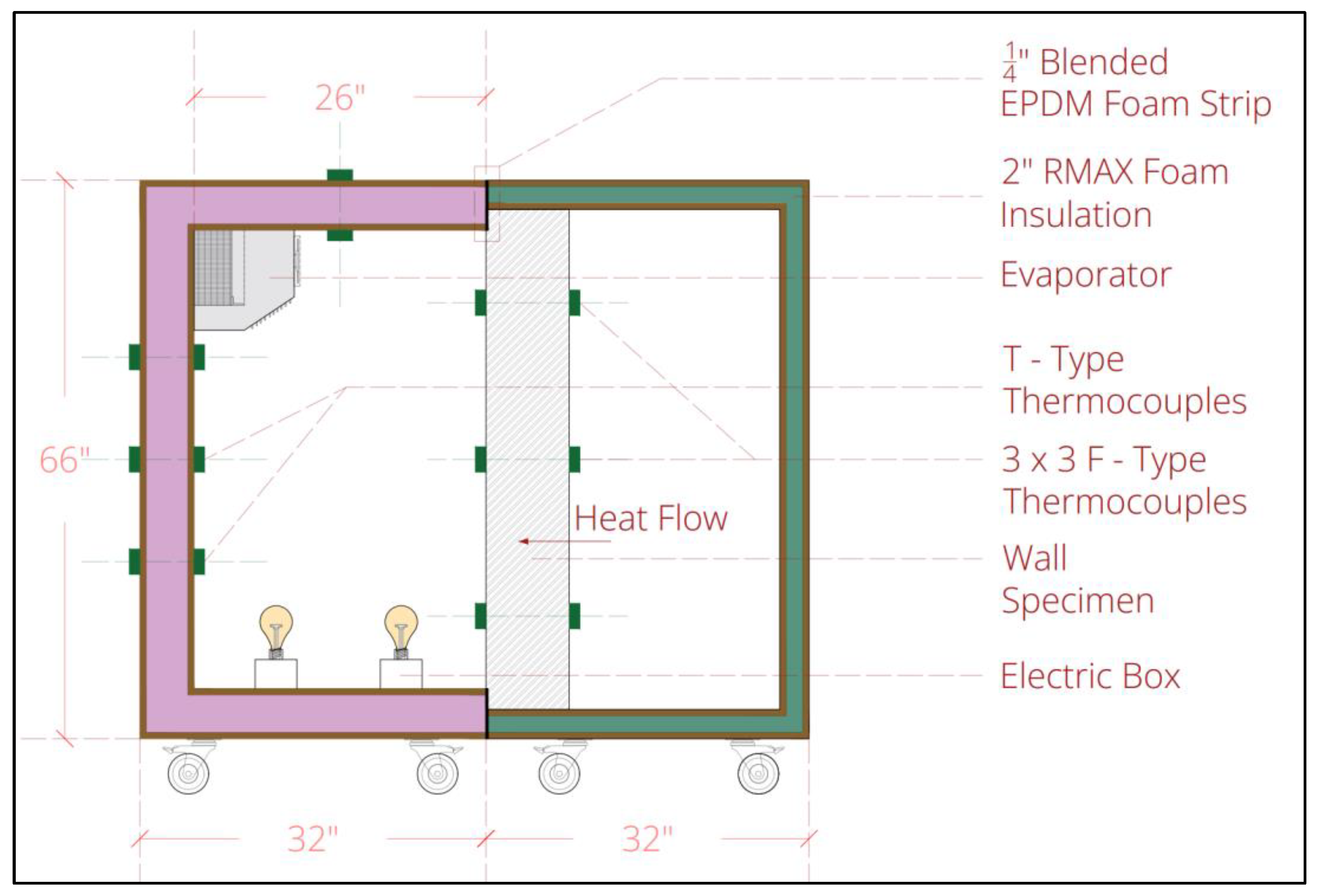
5.4.2. Cooling Chamber Design
The cooling chamber was designed in this study in accordance with ASTM C1363-19 and ISO 8990-96 standards. The climatic chamber and metering chamber were made portable by selecting opening dimensions of 152 cm by 152 cm (5 ft by 5 ft) for the climatic chamber and 137 cm by 137 cm (4.49 ft by 4.49 ft) for the metering chamber, as shown in
Figure 6 and
Figure 7. Referring back to step 1, the cooling chamber that was constructed using calibrated environmental chamber configuration consisted of only a climatic chamber and a metering chamber without a guard chamber. This cooling chamber was constructed differently from the heating chamber to ensure that the cooling chamber could accommodate the cooling unit (i.e., chiller) inside the metering chamber without increasing its size beyond standard door openings in the United States and to maintain the portability of the cooling chamber. This modification was necessary to enable easy movement of the chamber between locations to conduct thermal performance measurements for building envelopes. Additionally, the metering chamber depth was selected to be 66 cm (26 inch) to fit in all the devices and sensors and the cooling system inside, and the climatic chamber depth was selected to be 74 cm (29 inch), as shown in
Figure 6. Additionally,
Figure 7 presents a schematic design of the cooling chamber, including a metering chamber equipped with five 150-Watt T8 dimmable halogen light bulbs and a refrigerated cooling system that includes an R134A compressor, an evaporator, a condenser, two fans for the evaporator, one fan for the condenser, and a capillary tube, which is the metering device. The cooling system is similar to cooling systems that can be seen in typical refrigeration systems. The designed calibrated environmental chamber was designed to conduct thermal performance measurement experiments for building envelopes as low as −20 °C (4 °F). The building envelopes are placed between the metering chamber and the climatic chamber for testing their thermal performance. A Light Duty Blended EPDM Foam Strip was added all around the frame of the metering and climatic chambers to minimize losses at the point of intersections.
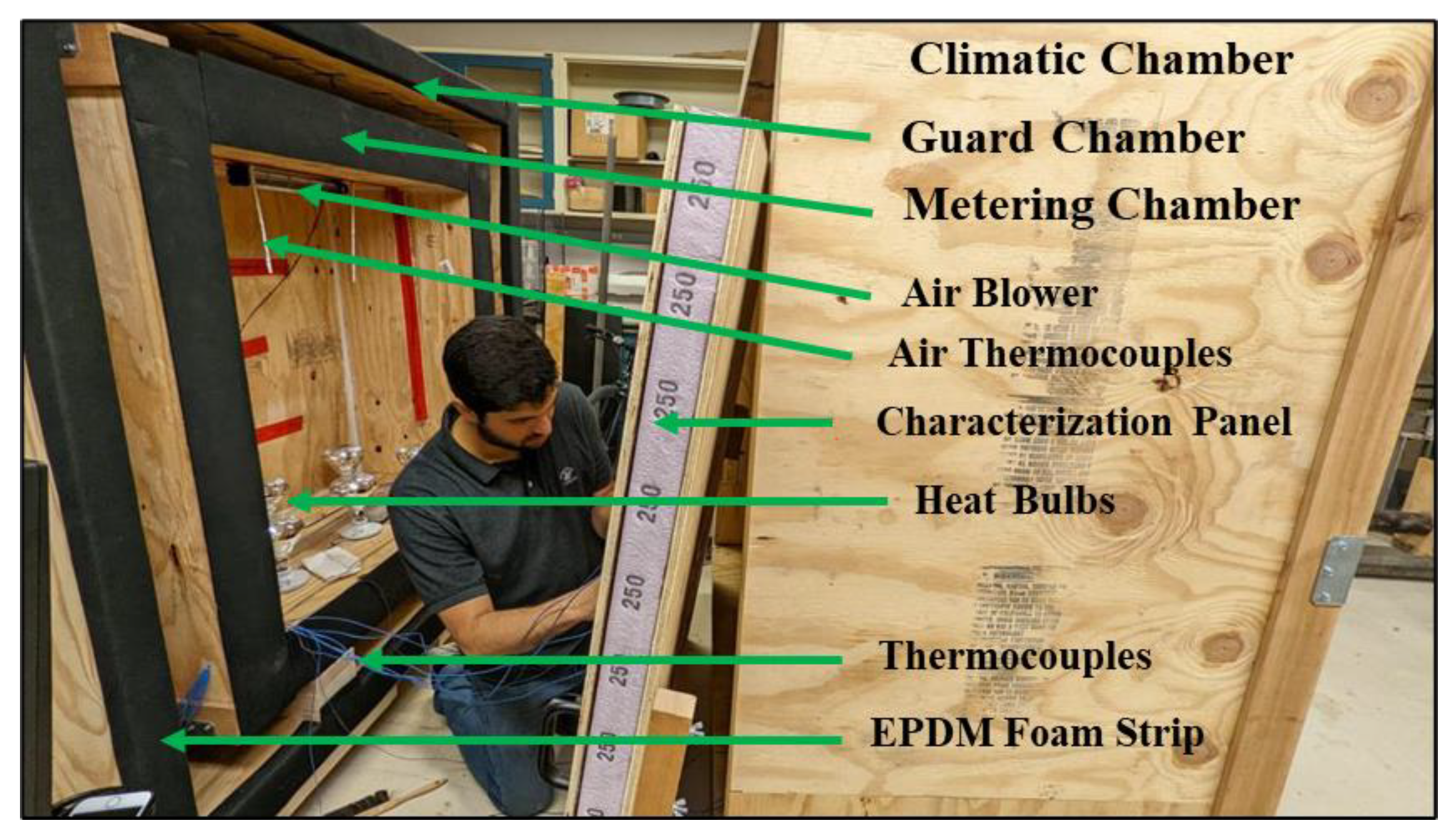
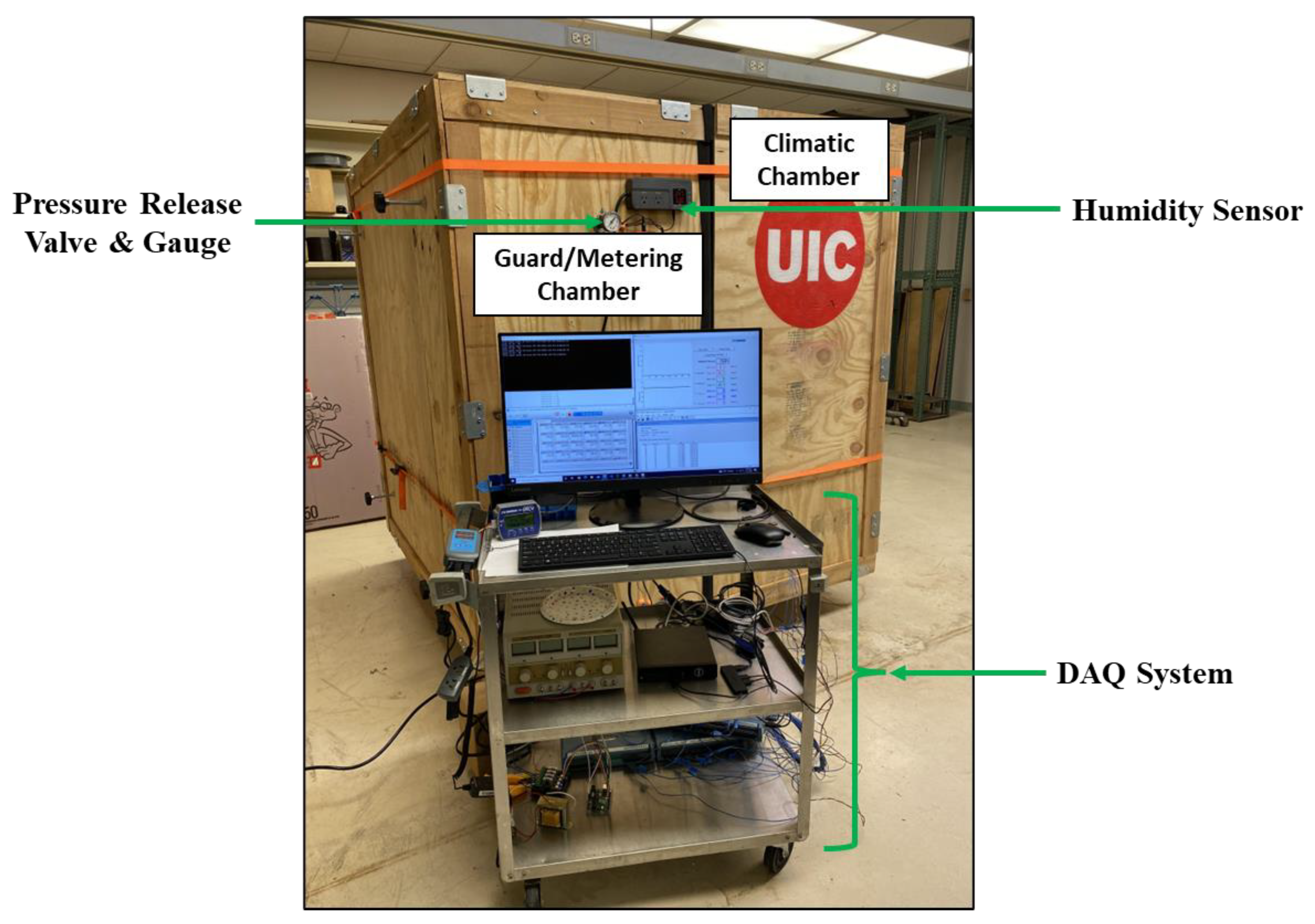
5.5. Setting up and Calibrating Data Acquisition (DAQ) System
A sturdy system for data acquisition (DAQ) was created to precisely gauge the thermal properties of building envelopes through the guarded and calibrated environmental chambers. The DAQ system comprised T-Type 24AWG wire thermocouples (item # TT-T-24-SLE®), Omega heat fluxes (type UHFS-09®), an Omega HFS DAQ® data logger, relative humidity (RH%) sensors (Inkbird ITC-608T humidity controller), a desktop computer, InstaCal® software from Omega Engineering company in Norwalk, CT, USA, DAQami® software from Omega Engineering company in Norwalk, CT, USA, and a temperature control system that utilized Arduino and Python code. The InstaCal® software and DAQami® software, which were used in this study, can operate on any Windows computer system.
To accurately measure the thermal performance of building envelopes, thermocouples were installed on the surface of a wall panel specimen (i.e., a calibration wall panel specimen in this study) using foil tape and Gorilla tape to ensure that only the surface temperature was accurately measured, and air pockets were minimized. In total, 56 T-Type 24AWG wire thermocouples were set up in the metering chamber walls and on both sides of the wall specimen of the heating chamber to conduct experiments under hot weather conditions, and another 56 T-Type 24AWG wire thermocouples were set up in the metering chamber walls and on both sides of the wall specimen of the cooling chamber to conduct experiments under cold weather conditions, following the ASTM C1363-19 standard (see
Figure 4,
Figure 5,
Figure 6 and
Figure 7). Among them, 38 thermocouples were equally distributed to the inner and outer surfaces of the metering chamber walls (19 thermocouples on each side) to measure the surface temperature inside and outside of the metering chamber, and the remaining 18 were equally distributed on both sides of the wall panel specimen (9 thermocouples on each side) to measure the surface temperature on the front side (i.e., facing the guard chamber and/or metering chamber) and on the rear side (i.e., facing the climatic chamber) (see
Figure 4,
Figure 5,
Figure 6 and
Figure 7). The total number of thermocouples in this study met the minimum requirements for the number of thermocouples per square meter, a minimum of 5 thermocouples per m
2, in an environmental chamber following the ASMT C1363-19 standard. Additionally, two Omega heat flux sensors of UHFS-09 type were added to measure the heat flow through building envelopes. UHFS-09 is an ultra-sensitive plate heat flux sensor with a sensing area of 52 cm
2 designed with very high sensitivity, which makes it ideal for accurately measuring relatively low heat fluxes.
The 56 thermocouples were connected to four Omega 16-channel high-tech data acquisition (DAQ) systems of type OMB-DAQ-2416
®, which provided 64 active thermocouple channels for measuring and recording temperature readings in different weather conditions across the environmental chamber. The DAQ devices were identified by their respective serial numbers, DAQ device 1: 01FFDE38 and device 2: 01FFDE3B, and the expansion devices for DAQ device 1 and 2 were 1FDB401 and 1FDB406, respectively. The installed DAQ device 1 along with its expansion device were used to measure and record all the thermocouple readings that were placed inside the metering chamber and on the front side of the test specimen (i.e., facing the guard chamber and/or metering chamber simulating outdoor environmental condition) for both heating and cooling chambers, individually. The installed DAQ device 2 along with its expansion device were used to measure and record all the thermocouple readings that were placed outside the metering chamber of the heating and cooling chambers and on the rear side of the test specimen (i.e., facing the climatic chamber simulating indoor environmental condition). The two UHFS-09 type heat flux sensors were connected to an Omega HFS DAQ
® data logger, which was then connected to a computer using a USB cable interface with InstaCal
® and DAQami
® software installed to calibrate the thermocouples and record the readings [
31]. The HFS DAQ
® data logger accurately measured the small analog DC voltage signals output from the UHFS-09 heat flux sensor. The temperature and heat flux sensor measurement signals were viewed and recorded simultaneously using the HFS DAQ
® software program. Additionally, two Inkbird ITC-608T humidity controller sensors were added to the DAQ system to measure and record the relative humidity (RH%) on both sides of the wall specimen (i.e., heating/cooling chamber and climatic chamber). A quick test was then run to ensure that the DAQ systems were operating and recording temperature and heat flow measurements every 5 min for both heating and cooling chambers, which is the minimum number of readings required by ASTM 1363-19, as well as measuring and recording the RH% inside the environmental chamber. To ensure that all the instruments and sensors installed in the environmental chamber were functioning properly without any defects, a quick test was conducted. This test involved turning on the installed DAQ system and all the connected instruments/sensors, such as thermocouples, heat flux sensors, humidity sensors, and a temperature control system that utilized Arduino and Python code, along with their related software (InstaCal
® software and DAQami
®).
Table 1 shows the measuring ranges and accuracies of all the instruments and sensors used in this study. To evaluate their efficiency and workability, all the instruments/sensors were exposed to a high temperature of 70 °C (167 °F) and a low temperature of −20 °C (−4 °F). The primary objective of this test was to ensure that all the installed instruments/sensors were working optimally before conducting an actual experiment (e.g., characterization panel test). This test is critical because it allows any potential issues with the instruments/sensors in the DAQ system to be identified and addressed before closing and sealing the environmental chamber. This approach is less time-consuming and more straightforward than trying to resolve any problems that may arise during the actual experiment.
A temperature control system was then designed and added in the environmental chamber, which utilized Arduino and Python code to automate temperature control, measurement, and monitoring for the installed heat bulbs in both heating and cooling chambers.
5.6. Constructing the Environmental Chambers
Both the heating and cooling chambers were built following the ASTM C1363-19 and ISO 8990-96 standards.
5.6.1. Constructing the Heating Chamber
The heating chamber was built following the ASTM C1363-19 and ISO 8990-96 standards and the design of the environmental chamber in step 4 of this section to measure the thermal performance of building envelopes under hot weather conditions. Accordingly, the heating chamber was constructed including the three main components of environmental chambers: the metering chamber, the guard chamber, and the climatic chamber. According to the ISO 8990 [
9] standard, the metering chamber’s size should be the larger value between three times the square of the metered specimen thickness and 1 m
2. Since 1 m
2 is larger than the three times the square of any building envelope thickness that was tested in this study, the metering chamber’s interior dimensions were built to be 40 inch (L) × 40 inch (H) × 20 inch (D) (or 100 cm × 100 cm × 50 cm). The metering chamber was constructed using ½ inch (1.27 cm) plywood, 4 inch (10 cm) RMAX thermal insulation board, and ½ inch (1.27 cm) plywood. The climatic and guard chambers were built with interior dimensions of 60 inch (L) × 60 inch (H) × 29 inch (D) (or 152 cm × 152 cm × 74 cm) using ½ inch (1.27 cm) thick plywood, 2 inch (5 cm) thick RMAX thermal insulation board, and ½ inch (1.27 cm) thick plywood (see
Figure 8).
5.6.2. Constructing the Cooling Chamber
The cooling chamber was built following the ASTM C1363-19 and ISO 8990-96 standards to measure the thermal performance of building envelopes under cold weather conditions. Accordingly, the cooling chamber was constructed including two main components of an environmental chamber: the metering chamber and the climatic chamber. The metering chamber’s interior dimensions were built to be 54 inch (L) × 54 inch (H) × 26 inch (D) (or 137 cm × 137 cm × 66 cm). The metering chamber was constructed using ½ inch (1.27 cm) plywood, 5 inch (12.54 cm) XPS thermal insulation board, and ½ inch (1.27 cm) plywood (see
Figure 9). The same climatic chamber constructed for the heating chamber was used for the cooling chamber thermal performance tests.
5.7. Calibrating the Environmental Chamber
Both the heating and cooling chambers were calibrated separately following the ASTM C1363-19 standard, in which it requires tests to run for a period of five consecutive time constants with temperatures held at a steady state for both heating and cooling thermal performance experiments [
8]. The time constant, as defined by ASTM C1363-19, is the amount of time required for a system to return to within 37% of equilibrium after a temperature change. To calculate the time constant (Tc), a characterization panel test was necessary, which was performed using the constructed heating and cooling chambers (see
Figure 8 and
Figure 9). The characterization panel is a test panel of known thermal performance and known thickness. In this study, a characterization panel was constructed with the following specifications to meet the requirements of the ASTM C1363-19 standard: (1) ½ inch (1.27 cm) thick plywood of 60 inch × 60 inch (1.52 m × 1.52 m) area, mass of 5.46 lb (2.5 kg), density of 43.7 lb/ft
3 (700 kg/m
3), thermal conductivity of 0.068 BTU/hr ft °F (0.117 W/m °C), and R-value of 0.62 ft
2·°F h/BTU (0.11 m
2 °C/W), (2) 2in (5 cm) thick XPS insulation of 60 inch × 60 inch (1.52 m × 1.52 m) area, mass of 2.62 lb (1.2 kg), density of 2.5 lb/ft
3 (40 kg/m
3), thermal conductivity of 0.017 BTU/hr.ft. °F (0.029 W/m °C), and R-value of 10 ft
2·°F h/BTU (1.76 m
2 °C/W) at 75 °F (24 °C), and (3) similar to the first layer, ½ inch (1.27 cm) thick plywood of 60 inch × 60 inch (1.52 m × 1.52 m) area, mass of 5.46 lb (2.5 kg), density of 43.7 lb/ft
3 (700 kg/m
3), thermal conductivity of 0.068 BTU/h ft °F (0.117 W/m °C), and R-value of 0.62 ft
2 °F h/BTU (0.11 m
2 °C/W) at 75 °F (24 °C). Thus, the characterization panel resulted in a total thickness of 3 inches (7.54 cm) and an R-value of 11.2 ft
2 °F h/BTU (1.97 m
2 °C/W) at 75 °F (24 °C), satisfying the requirements outlined in ASTM C1363-19, including: (i) knowledge of all dimensions and thermal properties of the constructed characterization panel; (ii) a lightweight design to facilitate easy transport inside and outside the environmental chamber; and (iii) an R-value greater than 1 h ft
2 °F/Btu (0.176 m
2 °C/W) for the constructed characterization panel. This characterization panel test was then used to determine the total duration of the actual experiment for measuring the effective thermal performance (τ
eff) of building envelopes (i.e., wall panels in this study). To conduct the experimental time constant (Tc) measurements in accordance with the ASTM C1363-19 standard, the methodology is explained in nine main steps as outlined below.
A low R-value and lightweight wall panel specimen, called the characterization panel, was constructed (see
Figure 8).
The characterization panel was sealed and installed between both the heating and cooling chambers’ components. The testing conditions included setting and recording the metering chamber temperature from 5 to 10 °C below the target set point for the heating chamber and 5 to 10 °C over the target set point for the calibrated environmental chamber, following the ASTM C1363-19 standard. For this study, the temperature inside the metering chamber was set to: (1) 58 °C (136 °F) for the heating chamber, which is 7 °C below the target temperature of 65 °C (150 °F), and (2) −11 °C (12 °F) for the cooling chamber, which is 5 °C above the target temperature of −16 °C (3 °F).
The data acquisition (DAQ) system was used to measure and record the temperature readings inside and outside the heating and cooling chambers. The test was run first until a steady-state temperature of 58 °C (136 °F) was reached and maintained for five hours for the heating chamber (see
Figure 10) and a steady-state temperature of −11 °C (12 °F) for five hours for the cooling chamber (see
Figure 11).
Once the first steady-state condition was achieved, the test conditions were quickly changed to the target temperatures for both heating and cooling chambers, 65 °C (150 °F) and −16 °C (3 °F), respectively, in the metering chambers to maintain and stabilize the temperatures (see
Figure 10 and
Figure 11).
The temperature and time were recorded in the DAQ systems at 5 min intervals for both heating and cooling chambers.
The heat flow rate through the characterization panel specimen was calculated for both heating and cooling chambers.
The time versus temperature and net sample heat flow rate was plotted from shortly before the temperature change to the second time the heating and cooling chambers reached steady-state temperatures (see
Figure 10 and
Figure 11).
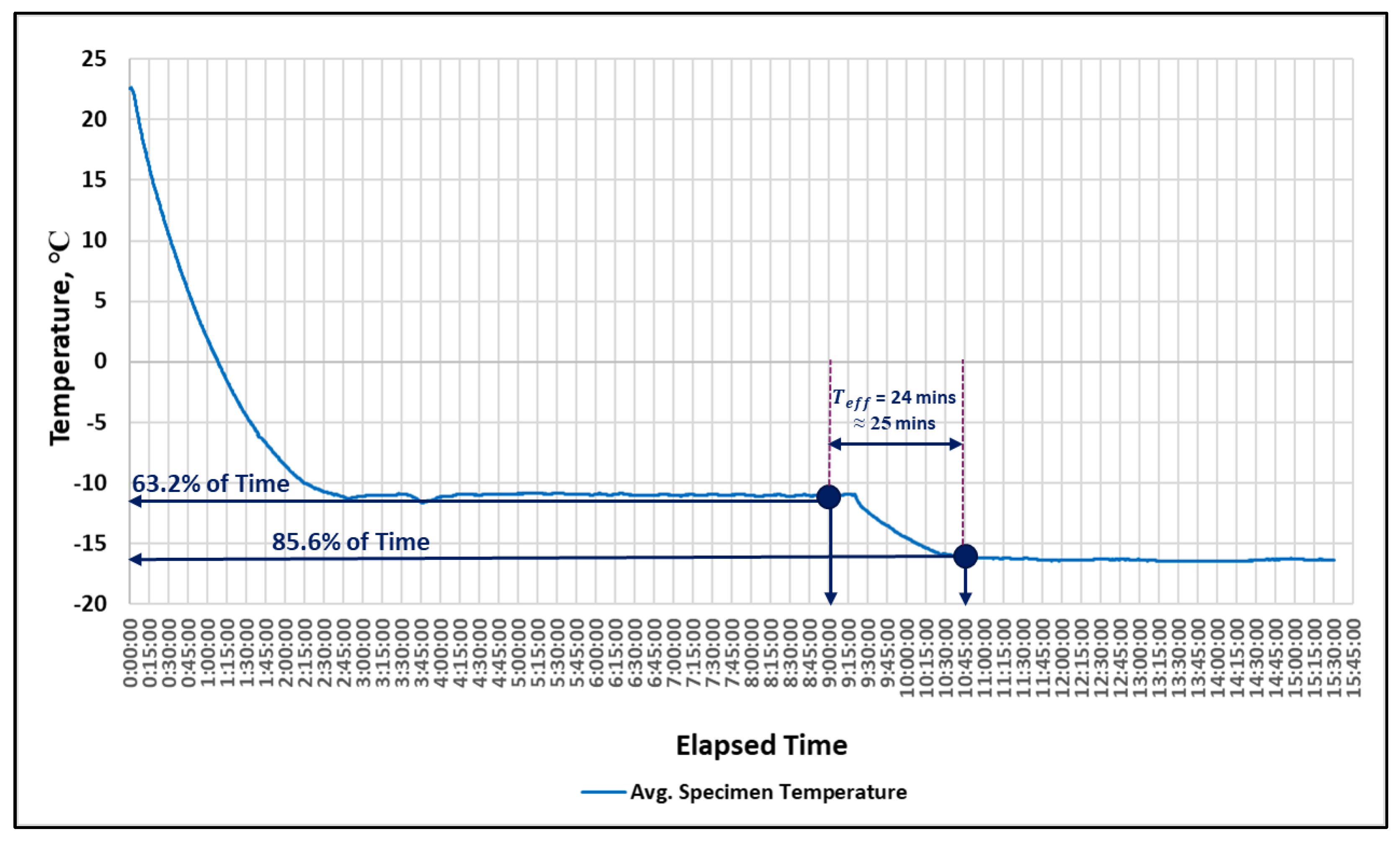
The time elapsed from the temperature change, where the 5 min averages of temperatures and heat flow were 63.2% and 85.6% of the final value, respectively, was determined for both the heating and cooling chambers (see
Figure 10 and
Figure 11).
The maximum difference in times for steady state conditions in both heating and cooling chambers equal to the time constant for the test system, τ
eff (i.e., effective thermal time constant of the environmental chambers and characterization panel specimen) was found. According to section A10.3.3.7 of ASTM C1363-19, the time constant for the test system (τ
eff) is the time the heating and cooling systems take to change their temperature for the period from shortly before the first steady state temperature change (i.e., 58 °C @ an elapsed time of 8:00 for the heating chamber and −11 °C @ an elapsed time of 9:00 for the cooling chamber) to the second time the environmental chamber reaches a steady state (i.e., 65 °C @ elapsed time of 10:00 for the guarded environmental chamber and −16 °C @ elapsed time of 10:45 for the cooling chamber). The characterization panel test for the heating chamber was conducted for about 15 h (see
Figure 12). As shown in
Figure 10, there was a time difference of 120 min between the first and second steady-state temperature changes in the guarded environmental chamber. Therefore, the time constant for the test system (τ
eff) was calculated using Equation (1):
The time constant for the test system (τeff) in the heating chamber was calculated as 27 min, and it was rounded to 30 min based on the flexibility of rounding the time constant for the test system specified in the ASTM C1363-19 standard. This illustrated that there is a need to run five consecutive readings (i.e., five cycles) of 30 min each (i.e., total of 150 min) when reaching the steady-state temperature of the target temperature of 65 °C (150 °F) to measure the thermal performance of wall panels under hot weather conditions.
Additionally, the characterization panel test for the cooling chamber was also conducted for about 15:30 h. As shown in
Figure 11, there was a time difference of 105 min between the first and second steady-state temperature changes in the cooling chamber. Therefore, the time constant for the test system (τ
eff) was calculated using Equation (2).
The time constant for the test system (τeff) in the cooling chamber was calculated as 24 min, and it was rounded to 25 min. This illustrated that there is a need to run five consecutive readings (i.e., five cycles) of 25 min each (i.e., total of 125 min) when reaching the steady-state temperature of the target temperature of −16 °C (3 °F) to measure the thermal performance of wall panels under cold weather conditions.
Figure 10.
Characterization panel test output for time constant (τeff) measurements in the heating chamber.
Figure 10.
Characterization panel test output for time constant (τeff) measurements in the heating chamber.
Figure 11.
Characterization panel test output for time constant (τeff) measurements in the cooling chamber.
Figure 11.
Characterization panel test output for time constant (τeff) measurements in the cooling chamber.
Figure 12.
Characterization panel test in the environmental chamber.
Figure 12.
Characterization panel test in the environmental chamber.
6. Discussion
The results of the characterization panel test confirmed that both the heating and cooling chambers met the requirements of ASTM-1363-19 and ISO 8990-96 standards and addressed limitations of previous studies of measuring the thermal performance of building envelopes using environmental chamber, as shown in
Table 2.
Additionally, the limitations of the constructed environmental chamber in this study can be summarized into two points: (1) testing the thermal performance of building envelopes in the constructed environmental chamber at temperatures below −20 °C (−4 °F) is beyond the capability of this chamber, as is the case with off-site manufactured environmental chambers seen in existing studies (e.g., [
13,
17]) to simulate extreme cold weather condition experiments in the state of Alaska in the United States and Northern Canada. However, this is not feasible due to the substantial cost and complexity associated with the modification of the existing environmental chamber by adding ultra-low temperature (ULT) or cryogenic cooling systems; and (2) performing extended experiments that simulate an entire season or year of weather conditions is beyond the capability of this chamber, as is commonly undertaken by national laboratories due to the limitations of the installed data acquisition (DAQ) system and associated instrumentation. Specifically, the current system is not designed to support experiments that span several months of data collection, which would be necessary to mimic seasonal changes in weather patterns.
Uncertainty Analysis
The uncertainty in measuring the R-values of the characterization panel in both the heating and cooling chambers was analyzed using the law of propagation of uncertainty, in accordance with the Guide to the Expression of Uncertainty in Measurement (GUM) method [
32]. To find the R-value of the characterization panel, we used Equation (3):
where:
= metering chamber opening area for heating and cooling chambers, m2;
= area weighted average temperature of the hot/cold surface of the characterization panel, K or °C;
= area weighted average temperature of the ambient surface (climatic chamber side) of the characterization panel, K or °C;
= time rate of net heat flow through the characterization panel, W;
= thermal resistance of the characterization panel, (m2.K/W).
Therefore, the combined uncertainty can be expressed as follows:
In this study, thermocouples were used to measure the temperatures (T
1 and T
2) on both sides of the constructed environmental chamber. Heat flux sensors were used to measure the heat flow through the characterization panel. Accordingly, the uncertainty of the R-values (
) was calculated along with the uncertainty of R-values at 95% confidence (i.e., multiplying the uncertainty R-value by 2).
Table 3 provides a summary of the uncertainty analysis results for both the heating and cooling chambers. The table displays two sets of error values: the error 1 values, which correspond to the error/accuracy range specified by the manufacturers (refer to
Table 1), and the error 2 values, which represent the calculated errors obtained from the standard deviation of the mean of the temperature readings at a steady-state condition, when the target temperatures were reached. The maximum error value was chosen for each variable, between the two sets of error values presented in the table for the calculations of the uncertainties. The findings indicated that (1) the heating chamber can measure the R-value of the characterization panel with an accuracy of ±0.73 ft
2·°F h/BTU (±0.129 m
2 °C/W) and with a 95% confidence accuracy of ±1.47 ft
2·°F h/BTU (±0.259 m
2 °C/W), and (2) the cooling chamber can measure the R-value of the characterization panel with an accuracy of ±1.02 ft
2 °F h/BTU (±0.180 m
2 °C/W) and with a 95% confidence accuracy of ±2.04 ft
2·°F h/BTU (±0.360 m
2 °C/W), as shown in
Table 3.
7. Conclusions
Researchers and building material testing companies have been facing difficulties measuring the thermal performance of building envelopes because of the high cost and prolonged waiting times at accredited laboratories. Consequently, designing energy efficient building components that can endure diverse climatic conditions in the United States has been challenging. To address this problem, this study developed and evaluated a cost-effective and portable heating chamber to conduct experiments in hot climates and a cooling chamber to conduct experiments in cold climates. This was achieved by seven main steps (see
Figure 1): (1) designing an environmental chamber for both heating and cooling testing experiments following the ASTM C1363-19 and ISO 8990-96 standards; (2) conducting a literature review to select appropriate construction materials for the environmental chamber that are practical and strong enough to withstand prolonged exposure to extreme high and low temperatures; (3) building and testing a prototype of the environmental chamber using the selected materials to validate their effectiveness in withstanding extreme temperatures and ensuring their compaction as a single structure; (4) finalizing the design of the environmental chamber; (5) setting up and calibrating a high-tech data acquisition (DAQ) system for the environmental chamber, as well as installing humidity, temperature, and heat flux sensors on the DAQ system, along with their related software; (6) constructing the environmental chamber and heating and cooling chambers following the requirements of the ASTM C1363 and ISO 8990 standards; and (7) calibrating the environmental chamber using a characterization panel test to measure the accuracy of the thermal performance results of building envelopes in extremely hot and cold climates at steady-state temperatures. The characterization panel is a constructed test panel of known thickness, thermal conductivity, and R-value that helps to (i) verify the capability of the constructed environmental chamber to withstand the targeted temperatures inside the metering chamber with the requirements of the standards at steady-state temperature conditions; and (ii) validate the accuracy of measuring the thermal performance of the constructed environmental chamber at steady-state temperature conditions.
The experimental findings indicated that the heating chamber was able to keep the temperature within ±0.5 °C at steady-state conditions and accurately measure the R-value of the characterization panel specimen with an accuracy of ±0.73 ft2·°F h/BTU (±0.129 m2 °C/W) under hot climate conditions of 65 °C (150 °F) and at a relative humidity of 29% in the heating chamber and 35.2% in the climatic chamber. Additionally, the cooling chamber was able to withstand temperatures within ±1 °C at steady-state conditions and accurately measure the R-value of the characterization panel specimen with an accuracy of ±1.02 ft2·°F h/BTU (±0.180 m2 °C/W) under cold climate conditions of −16 °C (3 °F) and at a relative humidity of 55.4% in the cooling chamber and 35% in the climatic chamber. These experimental findings demonstrated that the constructed environmental chamber and heating and cooling chambers effectively maintained steady-state temperatures in various climates in the metering chamber throughout the duration of the characterization panel test. The temperature of the metering chamber was maintained within the prescribed range of ±1 °C in both designs of heating and cooling chambers, satisfying the stringent requirements outlined in the ASTM C1363-19 standard. However, it is crucial to highlight that the environmental chamber was constructed in this study to accurately measure the thermal performance of building envelopes in various climates at “steady-state” thermal transmissions following both the ASTM C1363 and ISO 8990 standards, and it is not meant to conduct thermal performance experiments at “non-steady-state” conditions to find the dynamic thermal performance of building envelopes. The dynamic thermal performance measurements of building envelopes refer to the process of evaluating the ability of a building’s outer layer to resist heat transfer over time, while taking into account various factors such as temperature, solar radiation, and other environmental conditions. This assessment involves measuring the rate of heat flow through the building envelopes. The dynamic state evaluations require different experimental setups for the environmental chamber and the DAQ system than those specified in the ASTM C1363 and ISO 8990 standards, which is beyond the scope of the current study. The national laboratories usually use two different environmental chambers to conduct thermal performance experiments for building envelopes at steady-state and non-steady-state temperature conditions. Therefore, in this study, the time-dependent thermal properties were not studied as they were studied and measured in on-steady-state thermal performance experiments.
The findings of this study offer significant benefits to decision makers in the construction industry such as company owners, research labs, and manufacturers by enabling them to measure the thermal performance of building envelopes accurately in accordance with ASTM C1363 and ISO 8990 standards. The advantages of this approach are twofold: (1) it drastically reduces the cost of testing building envelopes by enabling the in-house construction of such an environmental chamber and an accurate measurement of thermal performance experiments without the need to send building envelope panels to external material testing labs, which eliminates the high costs associated with experimentation and transportation, unless an accredited sample certificate is required; (2) it shortens the waiting time to obtain the results since, with material-testing labs receiving a significant number of building envelope samples to test for thermal performance efficiency, decision makers often find themselves in long waiting lines, whereas with such an innovative environmental chamber constructed by in-house crews, decision makers can conduct building envelope panel experiments in-house, without the need to send them to external material testing labs, unless an accredited sample certificate is required. As a result, decision makers can make informed decisions regarding the design and selection of energy-efficient building components that can withstand varying climatic conditions.
Author Contributions
Conceptualization, H.P. and A.K.; methodology, H.P.; software, H.P.; validation, H.P. and A.K.; formal analysis, H.P.; investigation, H.P.; resources, H.P. and A.K.; data curation, H.P.; writing—original draft preparation, H.P.; writing—review and editing, A.K.; visualization, H.P. and A.K.; supervision, A.K.; project administration, A.K.; funding acquisition, A.K. All authors have read and agreed to the published version of the manuscript.
Funding
This research received no external funding.
Data Availability Statement
The data presented in this study are available on request from the corresponding author.
Acknowledgments
The authors of this study would like to express their sincere gratitude to Andrew Rener and Todd Tylor for their invaluable support and assistance throughout the course of this study. Their contributions have been instrumental in shaping the direction and outcome of this research.
Conflicts of Interest
The authors declare no conflict of interest.
References
- Pérez-Lombard, L.; Ortiz, J.; Pout, C. A review on buildings energy consumption information. Energy Build. 2008, 40, 394–398. [Google Scholar] [CrossRef]
- US International Energy Agency (IEA). Available online: https://www.iea.org/topics/buildings (accessed on 15 January 2023).
- Ürge-Vorsatz, D.; Cabeza, L.F.; Serrano, S.; Barreneche, C.; Petrichenko, K. Heating and cooling energy trends and drivers in buildings. Renew. Sustain. Energy Rev. 2015, 41, 85–98. [Google Scholar] [CrossRef]
- US Department of Energy (DOE). Windows and Building Envelope Research and Development: Roadmap for Emerging Technologies 2014. Available online: https://www.energy.gov/eere/buildings/articles/research-and-development-roadmap-windows-and-building-envelope (accessed on 30 March 2023).
- Ma, P.; Wang, L.-S.; Guo, N. Energy storage and heat extraction—From thermally activated building systems (TABS) to thermally homeostatic buildings. Renew. Sustain. Energy Rev. 2015, 45, 677–685. [Google Scholar] [CrossRef]
- Shen, Z.; Brooks, A.L.; He, Y.; Shrestha, S.S.; Zhou, H. Evaluating dynamic thermal performance of building envelope components using small-scale calibrated hot box tests. Energy Build. 2021, 251, 111342. [Google Scholar] [CrossRef]
- Seitz, S.; MacDougall, C. Design of an Affordable Hot Box Testing Apparatus. In Proceedings of the NOCMAT 2015, Mérida, Yucatán, Mexico, 26–29 November 2015. [Google Scholar]
- ASTM C1363; Standard Test Method for Thermal Performance of Building Materials and Envelope Assemblies by Means of a Hot Box Apparatus. ASTM International: West Conshohocken, PA, USA, 2019.
- BS EN ISO 8990; Thermal Insulation Determination of Steady-State Thermal Transmission Properties—Calibrated and Guarded Hot Box. International Organization for Standardization: Geneva, Switzerland, 1996.
- ASTM C177; Test Method for Steady-State Heat Flux Measurements and Thermal Transmission Properties by Means of the Guarded-Hot-Plate Apparatus. ASTM International: West Conshohocken, PA, USA, 2019.
- ASTM C518; Test Method for Steady-State Thermal Transmission Properties by Means of the Heat Flow Meter Apparatus. ASTM International: West Conshohocken, PA, USA, 2021.
- Alhawari, A.; Mukhopadhyaya, P. Construction and Calibration of a Unique Hot Box Apparatus. Energies 2022, 15, 4677. [Google Scholar] [CrossRef]
- Boudreaux, P.R.; Salonvaara, M.H.; Antretter, F.; Desjarlais, A.O. Comparing Wall Performance Predicted from Hygrothermal Simulations to Wall Performance Measured from Environmental Chamber Experiments; Oak Ridge National Lab. (ORNL): Oak Ridge, TN, USA, 2019. [Google Scholar] [CrossRef]
- Chowdhury, D.; Neogi, S. Thermal performance evaluation of traditional walls and roof used in tropical climate using guarded hot box. Constnstr. Build. Mater. 2019, 218, 73–89. [Google Scholar] [CrossRef]
- Ghosh, A.; Ghosh, S.; Neogi, S. Performance Evaluation of a Guarded Hot Box U-value Measurement Facility under Different Software based Temperature Control Strategies. Energy Procedia 2014, 54, 448–454. [Google Scholar] [CrossRef]
- Kus, H.; Özkan, E.; Göcer, Ö.; Edis, E. Hot box measurements of pumice aggregate concrete hollow block walls. Constr. Build. Mater. 2013, 38, 837–845. [Google Scholar] [CrossRef]
- Lucchi, E.; Roberti, F.; Alexandra, T. Definition of an experimental procedure with the hot box method for the thermal performance evaluation of inhomogeneous walls. Energy Build. 2018, 179, 99–111. [Google Scholar] [CrossRef]
- Mero, C.R. Design and Construction of a Guarded Hot Box Facility for Evaluating the Thermal Performance of Building Wall Materials. Master’s Thesis, Texas A&M University, College Station, TX, USA, 2012. [Google Scholar]
- Peters, B.; Sharag-Eldin, A.; Callaghan, B. Development of a simple Hot Box to determine the thermal characteristics of a three-dimensional printed bricks. In Proceedings of the ARCC 2017 Conference—Architecture of Complexity, Salt Lake City, UT, USA, 14–17 June 2017; pp. 14–17. [Google Scholar]
- Schumacher, C.J.; Straube, J.F.; Ober, D.G.; Grin, A.P. Development of a New Hot Box Apparatus to Measure Building Enclosure Thermal Performance. Proc. Build. XII 2013, 1–19. Available online: https://uwaterloo.ca/scholar/jfstraub/publications/development-new-hot-box-apparatus-measure-building-enclosure-thermal (accessed on 30 March 2023).
- Seitz, S.; Beaudry, K.; MacDougall, C. Thermal Performance of Panels with High Density, Randomly Oriented Straw Bales. J. Green Build. 2018, 13, 31–55. [Google Scholar] [CrossRef]
- Smith, S.K., II. Development of the Modified Hot Box: A Convective Heat Transfer Device for Measuring the Steady State and Transient Thermal Properties of Non-Homogenous Building Materials. Master’s Thesis, Clemson University, Clemson, SC, USA, 2016. [Google Scholar]
- Santos, P.; Gonçalves, M.; Martins, C.; Soares, N.; Costa, J.J. Thermal transmittance of lightweight steel framed walls: Experimental versus numerical and analytical approaches. J. Build. Eng. 2019, 25, 100776. [Google Scholar] [CrossRef]
- Björk, F.; Enochsson, T. Properties of thermal insulation materials during extreme environment changes. Constr. Build. Mater. 2009, 23, 2189–2195. [Google Scholar] [CrossRef]
- Andreotti, M.; Calzolari, M.; Davoli, P.; Dias Pereira, L.; Lucchi, E.; Malaguti, R. Design and Construction of a New Metering Hot Box for the In Situ Hygrothermal Measurement in Dynamic Conditions of Historic Masonries. Energies 2020, 13, 2950. [Google Scholar] [CrossRef]
- Trgala, K.; Pavelek, M.; Wimmer, R. Energy performance of five different building envelope structures using a modified Guarded Hot Box apparatus—Comparative analysis. Energy Build. 2019, 195, 116–125. [Google Scholar] [CrossRef]
- Grynning, S.; Jelle, B.P.; Uvsløkk, S.; Gustavsen, A.; Baetens, R.; Caps, R.; Meløysund, V. Hot box investigations and theoretical assessments of miscellaneous vacuum insulation panel configurations in building envelopes. J. Build. Phys. 2011, 34, 297–324. [Google Scholar] [CrossRef]
- Kivioja, H.; Vinha, J. Hot-box measurements to investigate the internal convection of highly insulated loose-fill insulation roof structures. Energy Build. 2020, 216, 109934. [Google Scholar] [CrossRef]
- Asdrubali, F.; Baldinelli, G. Thermal transmittance measurements with the hot box method: Calibration, experimental procedures, and uncertainty analyses of three different approaches. Energy Build. 2011, 43, 1618–1626. [Google Scholar] [CrossRef]
- Nardi, I.; Paoletti, D.; Ambrosini, D.; de Rubeis, T.; Sfarra, S. U-value assessment by infrared thermography: A comparison of different calculation methods in a Guarded Hot Box. Energy Build. 2016, 122, 211–221. [Google Scholar] [CrossRef]
- Omega Engineering. Available online: https://www.omega.com/en-us/ (accessed on 14 March 2023).
- Evaluation of Measurement Data—Guide to the Expression of Uncertainty in Measurement. Jt. Comm. Guides Metrol. 2008, 100, 1–116.
| Disclaimer/Publisher’s Note: The statements, opinions and data contained in all publications are solely those of the individual author(s) and contributor(s) and not of MDPI and/or the editor(s). MDPI and/or the editor(s) disclaim responsibility for any injury to people or property resulting from any ideas, methods, instructions or products referred to in the content. |
© 2023 by the authors. Licensee MDPI, Basel, Switzerland. This article is an open access article distributed under the terms and conditions of the Creative Commons Attribution (CC BY) license (https://creativecommons.org/licenses/by/4.0/).


