Abstract
Building Information Modeling (BIM) is a digital tool that can be used to create three-dimensional models of components. BIM technology, with its parameterized modeling scheme, can effectively address design changes. The use of BIM technology in prefabricated shear wall structures can significantly enhance component design accuracy and production efficiency. The Tekla software offers significant advantages in BIM deepening design. By utilizing the C# language, secondary development of the Tekla software, and the development of an intelligent modeling program for the edge components of prefabricated shear wall structures, the deepening design efficiency of such structures can be improved. The creation of BIM models is a crucial step in program development. Different types of reinforcements require various modeling methods, which, when combined with the design specifications of concrete structures, can be compiled to create the fine reinforcement model. This allows for the automatic creation of three-dimensional reinforcement models: “linear-shaped,” “T-shaped,” and “L-shaped” joints of the edge member. The BIM visualization characteristics can then display the three-dimensional model of the steel bar of the edge member in the cast-in-place area, deriving the engineering quantity of the steel bar for the production and construction of the prefabricated members. The modeling program’s development concept can serve as a reference for similar engineering applications, promoting the intelligent development of prefabricated building design and enhancing the efficiency of design and construction.
1. Introduction
With the continuous development of society, the construction industry has also changed from a traditional building mode to a convenient prefabricated building mode [1]. A prefabricated building conforms to the connotations of the modernization of the construction industry and is also one of the directions of the new construction industrialization. Building information modeling (BIM) is a booster of the modernization of the construction industry and a powerful tool for its transformation [2]. It can avoid human errors, reduce project costs, enhance productivity and quality, and shorten project delivery time [3]. Especially with the deepening of the application of BIM technology, the combination of BIM technology and prefabricated buildings has been a general trend.
At present, with the further development of BIM technology, its application research covers all aspects, such as building construction, three-dimensional deepening design, construction design, prefabrication technology development and so on. Sadhu A, Peplinski J E, Mohammad Khorasani A et al. explored various data management and visualization technologies using BIM, virtual reality, and augmented reality in structural information monitoring and summarized potential future research directions related to BIM and VR/AR in structural information monitoring [4]. Alizadehsalehi S, Hadavi A, and Huang J C. provided a comprehensive overview of the current research and market availability of BIM and XR technologies and adopted BIM and XR technologies to fill the gap In the Architecture, Engineering, and Construction (AEC) industry [5]. Fernández Rodríguez J F. optimized the design of MEP (mechanical, electrical, plumbing) facilities and buildings by developing virtual BIM models, promoting the implementation of this technology in the construction industry [6]. Hu Y, Xia C, Chen J, et al. proposed using Graph Convolutional Networks (GCN) to improve conflict change component prediction by considering the interdependence of building components based on the advantages of BIM in visual representation and spatial information processing [7]. Wang Wenjing proposed a BIM-based prefabricated building component automation system and concluded that the design results of this system were scientific, effective, and sustainable [8]. Zakeri et al. investigated the benefits, opportunities, costs, and risks (BOCR) associated with the implementation of BIM in a developing country while using a new multi-criteria decision-making approach (i.e., fuzzy reduced analytic Hierarchy Process) to analyze BOCR separately, providing practitioners with insights into the adoption of BIM [9]. Ren Xingchen introduced a technical route for the application of prefabricated BIM technology in the whole life cycle stage and concluded that the integrated application of the existing BIM software and self-developed BIM software could optimize the design scheme and construction and facilitate the later operation and maintenance [10]. Gharaibeh L, Matarneh S, Eriksson K, and Lantz B found that BIM technology could provide solutions for steel bar collisions between prefabricated shear wall structures, for the construction checking calculation of PC components, hydropower reservation and pre-embedding [11]. Cavalliere C, Dell’Osso GR, Favia F, and Lovicario M proposed a new method to evaluate the flexibility level of buildings by introducing six selection criteria, which were implemented in the BIM environment by coupling building information modeling (BIM) and Visual Programming language (VPL) tools. The use of programming language could provide more possibilities for the application of BIM technology [12]. Forcael E et al. adopted the method of defining variables based on a literature review to develop a model representing BIM users based on multiple parameters. The developed model could analyze the level of BIM users according to the defined parameters [13]. Li H, Zhang J, Chang S, et al. developed mapping algorithms that can connect BIM and analytical models. This study will help fill the information gap between BIM and analytical models [14]. Alizadehsalehi S and Yitmen I. presented a framework of an automated construction progress monitoring system that integrates BIM, various reality capturing technologies, DT and XR technologies (VR, AR and MR); arraying the steps on how these technologies work collaboratively to create, capture, generate, analyze, manage and visualize construction progress data, information and reports [15]. Honghong S, Gang Y, Haijiang L et al. compared and analyzed 116 documents on BIM and DT; a crucial metrics-based performance hierarchy for twin digital bridge was concluded, and a DT-enhanced BIM framework was proposed to promote full lifecycle digital bridge engineering implementation [16]. In view of the prominent problems in the detail design of prefabricated shear wall structures, Hu Jinxin developed BIM software to deepen the design of the detailed structure drawing through secondary development technical means [17].
The application of BIM in construction projects is conducive to effective decision-making of the whole project within its life cycle, and it can maximize benefits without affecting practicability [18]. The BIM method is used for technology integration, and the whole life cycle of prefabricated buildings, including design, production, construction, decoration and management, is more in line with the development concept of prefabricated buildings and the requirements of industrial production [19]. BIM technology can realize the life cycle management of prefabrication construction, further optimize production, reduce costs, shorten the construction cycle, and promote the development of prefabrication construction [20].
Maintaining the general trend of building industrialization, Wang analyzed the requirements for the design, production, transportation and construction stages of prefabricated buildings and proposed to use BIM technology as the carrier to realize the collaborative management of prefabricated buildings [21]. In order to promote the application of BIM in the design of prefabricated buildings, Bhola J compared the BIM of collaborative design with traditional design methods and established a conceptual model of PCP collaborative design based on the requirements of the IDM BIM technology to determine the accuracy of the BIM model in different design stages [22]. Aiming at the process of green building design in China, Li Q et al. proposed an extensible LCA/LCC method combined with the BIM platform and implemented the method with tools developed based on Revit [23]. Abd Razak studied the benefits of BIM integration with DfMA (Design for manufacturing and assembly). The study indicated that the application of DfMA in the construction industry will also improve its ability to transform the automation industry [24]. Qi B proposed a novel BIM-based DfMA framework for prefabricated components and modular components, which shows great potential in the design and application of prefabricated components [25]. Xu Z proposed a model view transfer method for the forward design of prefabricated buildings. Data mapping and IfcDoc (Ifc Documentation Generator) tool output are used to complete the file generator transmission of model view, which can solve the problems of redundant model information, heterogeneous data information and low transmission efficiency [26].
The application of BIM technology in the deepening design process of prefabricated structures will help to improve the quality and efficiency of the deepening design process and improve the production process of prefabricated component manufacturing [27]. In addition, the application of BIM technology can not only improve the efficiency of project management but also the construction quality of prefabricated buildings [28]. Construction personnel can efficiently carry out prefabricated construction with the help of BIM technology to complete the connection between component manufacturers and designers [29]. With the help of BIM, the site process can be modeled and handed over to the manufacturer. The BIM model can provide all the details of the prefabricated components and contribute to their production [30], significantly improve the efficiency and precision of the BIM model [31], and reduce the workload of the designer [32]. In the field of prefabricated BIM, one of the key obstacles to maximizing BIM benefits is the development of BIM software libraries and programs to convert the information from the BIM model to production and construction information [33]. Therefore, it is very necessary to develop BIM software.
By analyzing research on the development and application of prefabricated BIM technology, it is found that the combination of BIM technology and prefabricated buildings is more dependent on the development of a software platform. The further development of BIM technology requires the establishment of software platforms suitable for different fields and scenarios in order to better support and promote the development of prefabricated buildings.
The research in this paper mainly focuses on Tekla. In terms of structural deepening design, the Tekla deepening process has the advantages of zero component size error, small embedded error, high design accuracy, parametric modification design, etc., which is more in line with the development trend of deepening design in the prefabricated process [34]. The structural model generated by Tekla has accurate details of the building, which can be used for the simple and effective visual management of engineering projects, and the BIM model can also be used for the collaborative work of the workflow. It is a software solution that can effectively integrate models and non-models. In addition, the secondary development of Tekla Structures can expand the function of the software and connect some of the original drawing functions of the Tekla software in series so that the rules formulated can be incorporated into the secondary development program to improve efficiency and reduce the error rate [35]. Using C# programming language and BIM software’s secondary development technology, the automatic generation of reinforcement models and automatic export of reinforcement drawings can be realized, saving designers time on model construction [36]. Through the combination of BIM and C# language, the function of the BIM application can be expanded, the work burden of practitioners can be reduced, the time and labor costs for the construction of projects can be saved, and the benefits of BIM in production and construction can be improved. In order to make full use of the three-dimensional design function of the Tekla software, it is necessary to develop corresponding design tools for prefabricated building structure types.
Therefore, through the in-depth analysis of the Tekla software, this paper proposes the idea of intelligent modeling for the edge components of prefabricated buildings. Combining computer language and BIM technology, the Tekla software is selected as the deepening design software and is committed to realizing the intelligent application of the BIM software and accelerating the development of our country’s assembly-type building industry. In this paper, the secondary development technology is used to achieve the purpose of quickly building the prefabricated shear wall structure model. For all kinds of reinforcement contained in the edge component, the specification research is carried out, and the rapid modeling of the edge component is completed through C# language programming. On the basis of the completion of intelligent modeling, the Winform application program is further developed to improve the intelligence level. Users can realize the intelligent creation of the BIM model by inputting the corresponding parameters. In this paper, the development ideas and methods of the model of assembled shear wall edge members are elaborated on in detail. Through the development of this paper, a feasible technical approach is explored for information exchange during the design and construction phase.
2. Basic Specification Analysis of Edge Members of Prefabricated Shear Wall Structures
2.1. Classification of Edge Members of Prefabricated Shear Wall Structures
As an important part of the prefabricated shear wall structure, the edge members of the prefabricated shear wall structure are generally set in the cast-in-place joint area. According to China’s Code for Seismic Design of Buildings [37], edge members are load-bearing members of the prefabricated shear wall structure. In order to ensure the seismic strength of the prefabricated shear wall structure, the main splitting forms of the shear wall structure, as shown in Figure 1 (The shaded part is the layout range of edge components), include the edge dark column (linear shaped), the edge end column, the edge wing wall (T shaped) and the edge corner wall (L shaped).
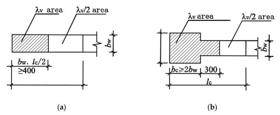
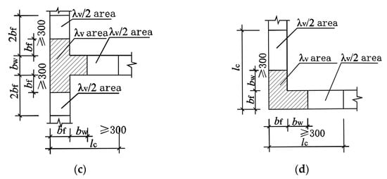
Figure 1.
Main types of splitting of edge components in shear wall structures: (a) Edge hidden column; (b) Edge end column; (c) Edge wing wall; (d) Edge corner wall.
2.2. Structural Requirements of Edge Members of Prefabricated Shear Wall Structures
According to the code for the seismic design of buildings’ aseismic walls, the vertical and horizontal distribution of the steel reinforcement ratio should not be less than 0.25%; the steel should not be less than 10 mm in diameter, and spacing should not be greater than 300 mm [34]. The longitudinal reinforcement at the edge of the component joints is bound and connected via mechanical connections and welding connections. For example, the edge members are mechanically connected; that is, the reserved interlace length is ≥500, and the interlace length is ≥500 + 35 × d. As shown in Figure 2, the details of three lashing ways of longitudinal reinforcement are shown. The binding requirements are determined based on the diameter of the steel bars and the anchoring length.
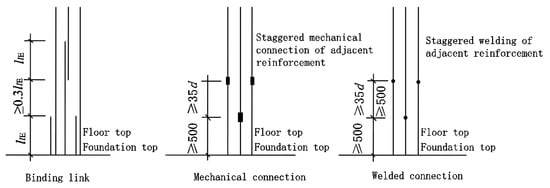
Figure 2.
Longitudinal reinforcement connection structure of shear wall edge members.
According to its main component classification and construction requirements, the modeling scheme in this paper is linear-shaped, T-shaped and L-shaped. The main reinforcement configurations include vertical longitudinal reinforcement, horizontal stirrup and tie reinforcement. Therefore, this paper will analyze and explain the creation of the prefabricated shear wall edge member model and reinforcement modeling methods.
3. Analysis of Design Thinking of Parametric Reinforcement for Edge Members
According to the classification requirements of the edge member, the joint structure form is defined. The reinforcement types of the edge member joint mainly include longitudinal reinforcement, stirrup reinforcement and tension reinforcement. The concrete process of longitudinal reinforcement modeling is, according to the design specifications and engineering information overview, to determine the position of the steel corner, according to the distribution parameters of longitudinal reinforcement, in a unified linear range, through a C# language set cycle algorithm, from the corner reinforcement to complete all longitudinal reinforcement modeling. Based on the attributes of the Polygons of the steel bar group of the stirrup and tensile reinforcement generated by TeklaOpenAPI, the construction algorithm of the stirrup and tensile reinforcement is designed according to the basic position of the longitudinal reinforcement, which is used to determine the construction point of the reinforcement, and then the stirrup and tensile reinforcement are generated. The above model for the modeling and reinforcement deepening design is completed, and a complete assembled shear wall structure edge component model is generated.
The design idea for parametric reinforcement is shown in Figure 3.
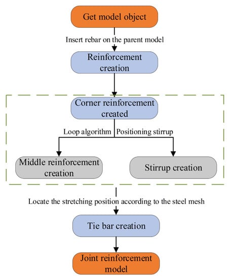
Figure 3.
Detailed design ideas.
4. Three-Dimensional Reinforcement Design Model
Visual Studio is an integrated development environment developed by Microsoft that provides a unified platform for developers to create, debug, and deploy various types of applications. C# is an object-oriented programming language developed by Microsoft and is one of the most commonly used programming languages for Visual Studio. Visual Studio supports a variety of programming languages, C# being one of the main ones. C# language was used for secondary development via the Visual Studio software; the software version adopted in this paper is the 2015 version, and the software itself does not contain the TeklaOpenAPI package. Different versions of Tekla correspond to different versions of TeklaOpenAPI. The 2017 version of Tekla is used in this paper, so the 2017.0.6809 package is introduced through the NuGet package management function. It is worth noting that it is not allowed to introduce packages that do not correspond to the version or the latest package of the current version; this may cause incompatibility and hinder subsequent development.
4.1. Model Creation
4.1.1. Reference Namespace
After the TeklaOpenAPI package is installed, you need to reference the namespace in order to create objects, reference object methods, and modify object properties. Different namespaces correspond to different Tekla functions, such as:
Tekla.Structures.Model namespace includes the ability to insert, select, modify, or delete the object in Tekla’s internal structure model. Namespaces also include the possibility of querying different instances of the current data model, such as information about the currently selected object.
Tekla.Structures.Geometry3d namespace contains the basic classes required by Tekla for three-dimensional geometry structures. In addition, several accessibility features are provided to simplify the use of these classes.
Tekla.Structures.Model.UI namespace includes some classes that can be used to highlight the user interface objects.
Objects are created based on classes; different classes exist in different namespaces, and using different namespaces can achieve different manipulations of the Tekla software. Using different namespaces allows the realization of the modeling function of the cast-in-place joint structure. The following commands are invoked in the software.
- TSM = Tekla.Structures.Model;
- T3D = Tekla.Structures.Geometry3d;
- TSUI = Tekla.Structures.Model.UI;
4.1.2. Creating the Model in the Tekla Spatial Coordinate System
The Tekla.Structures.Mode namespace in Tekla-API contains the class that creates the model object. The TSM.Model Class is used to create the Model object, which contains methods that operate on the Tekla model space. The TSUI.Picker Class is used to create Picker objects that contain point coordinate methods that can pick up the model space and return point coordinate value variables. The TSM.Beam Class is used to create Beam objects. The model objects of the edge artifacts in Tekla are created from Beam objects, as shown in Figure 4.
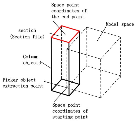
Figure 4.
Spatial schematic diagram of column member model.
Profile.ProfileString property gives the Beam object section shape parameters, which are used to generate section shapes. Beam.Insert () causes the Beam object to be generated in the model space. When the Beam object has the above properties, the corresponding artifacts are generated in the space model. Beam. Material. MaterialString object MaterialString Material properties. The Position.RotationOffset attribute determines the rotation offset of the column with respect to the origin. CommitChanges() refreshes the space model. A partial code example is shown below:
- L.Profile.ProfileString = NEWL;//Section name
- L.Material.MaterialString = “C40”;//Strength grade of concrete material
- L.Class = “6”;//Spatial model color level
- L.Insert();//Insertion model
- myModel.CommitChanges();//Refresh space model
This is used to create a model in Tekla through a programming language; Figure 5 shows the creation of an “L-shaped” joint model.
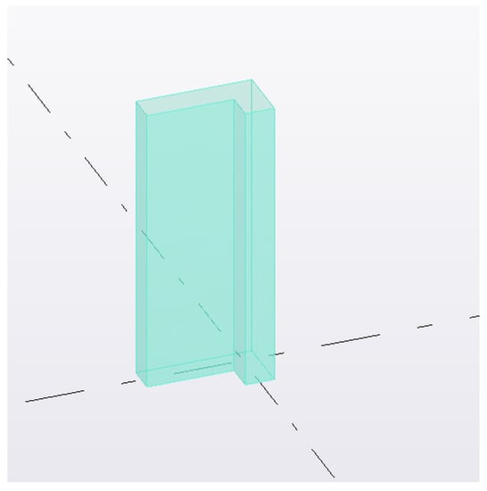
Figure 5.
“L-shaped” joint model in Tekla.
4.2. Get Model Object
The prime minister obtains the TSM.Solid object entity of the “L-shaped” component in the model space, and uses the PickerObject method inside the model space to obtain the selected L-shaped model object. When the model object is converted from the world coordinate system to the local coordinate system, this method can manipulate each key information parameter of the object entity. The main information contained in the object entity is shown in Figure 6.
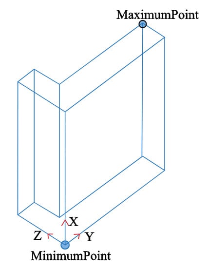
Figure 6.
TSM. Solid spatial coordinate diagram of “L-shaped” component.
The “L-shaped” component’s length value is obtained from the MaximumPoint and MinimumPoint property values for the X, Y, and Z coordinates of the L-shaped component. For example, when modeling the rebar modeling module, the MaximumPoint.X and MinimumPoint.X attributes in the model component Solid object are read, and then the height information of the component can be obtained by simple addition and subtraction operations.
- lengthOfXDirection = MaximumPoint.X − MinimumPoint.X;
- lengthOfYDirection = MaximumPoint.Y − MinimumPoint.Y;
- lengthOfZDirection = MaximumPoint.Z − MinimumPoint.Z;
The length, width and height sub-information of the model object is obtained, and this calculation method is used to locate the reinforcement information. The reinforcement position information needs to calculate the thickness of the protective layer.
4.3. Longitudinal Bar Creation
4.3.1. Basic Attributes and Modeling Ideas
A polygon’s attribute is used to describe the shape of the steel bar. Polygon-type parameters can draw the polygon shape of the steel bar, including longitudinal reinforcement, stirrup, etc., including but not limited to shaping the entity of two points and four points. The longitudinal reinforcement entity is created by connecting points to points.
Polygon.Points.Add() is used to add the three-dimensional coordinates of the start point and the spatial coordinates of the endpoint.
Insert() indicates rebar object insertion.
Bar.Polygon.Points.Clear() clears the coordinates of the space points within the rebar object for subsequent use.
The two coordinate points of the longitudinal reinforcement are added through the Add method for the reinforcement object. The coordinate points belong to the three-dimensional coordinate points in the space range. According to the obtained information of the model object, the two-point positions of the longitudinal reinforcement are determined by means of addition and subtraction calculation or migration, and the longitudinal reinforcement model is defined through two points.
4.3.2. Determine the Position and Length Information of Corner Reinforcement
The position and length of the steel bar are determined according to basic information such as engineering information, construction requirements, site category, seismic grade, etc. After the thickness of the protective layer is determined, the position of the steel bar is calculated through the spatial position. The longitudinal reinforcement layout diagram is shown in Figure 7.
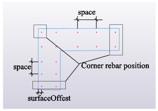
Figure 7.
Longitudinal reinforcement layout plan.
Based on the position analysis of the model in the figure above, the relationship between position and length in the local coordinate value system is shown as follows.
Location information:
surfaceOffest = Cover + commonBarSize/2 + stirrupBarSize/2
Length information:
RebarmodelLength = (MaximumPoint.XMinimumPoint.X) − Cover + RebarreservedLength
4.3.3. Create the Middle Longitudinal Bar
The judging process of the central reinforcement algorithm is shown in Figure 8.
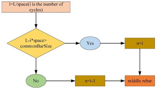
Figure 8.
Corner rebar creation process.
Based on the position relation of the Angle bars in the local coordinate system, the number of bars in the middle of the reinforcement is determined by the algorithm. In the vertical direction, the steel bars from the lower two corner points are generated upward through circulation. Assuming that the distance from the lower corner point to the thickness of the horizontal wall is L, the number of steel bars n is calculated through the standard spacing space of the steel bars. When determining the number of steel bars, it is necessary to ensure that the spacing, c, between two steel bars should not be less than the diameter of the steel bars, commonBarSize, to avoid the collision of steel bars.
By calculating the ratio between the Angle bar’s spacing bar L and the standard bar spacing space, we obtain the integer digit, which is the number of cycles, namely, the number of spacing created by the Angle bar towards the upper limb. The spacing between L and i*space must not exceed the commonBarSize of the steel bar diameter, and the inner steel bar of the vertical wall limbs must not extend to the corner part of the “L” model.
The middle rebar is created according to the correct number of rebar n. The resulting three-dimensional view of the longitudinal rib model is shown in Figure 9 (The purple lines in the model represent the longitudinal bars).
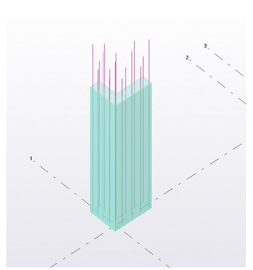
Figure 9.
Longitudinal reinforcement layout 3D in Tekla.
4.4. Stirrup Creation
4.4.1. Basic Attributes
To create the stirrup, create the “L-shaped” component stirrup and assign the stirrup group objects the RebarGroup attributes. Then, add different radius values according to the Stirrup bending radius attribute of the Stirrup object.
FromPlaneOffset represents the upper and lower surface offset values of the three-dimensional coordinate group of the start and end points of the stirrups object with respect to the three-dimensional coordinate X of the “L-shaped” member.
- StartPointOffsetValue: Sets the offset values of the stirrup start and end points of the stirrup group object;
- StartHook.Shape: Set the hook shape of the stirrup set;
- StartHook.Length: Length of the hook;
- StartHook.Radius hook Angle.
4.4.2. Modeling Idea
The upper and lower sections of the stirrup objects are defined by combining the TSM.Solid three-dimensional coordinate Points and the Polygon. Polygon1 objects were first positioned at the four coordinate points according to the stirrup shape. The position of the four coordinate points (1, 2, 3, and 4) are shown in the figure. According to the definition of a Polygon, shape point 1 should be added repeatedly to form a closed loop to complete the creation of the starting surface of the stirrup layout. Polygon2 objects are created in the same way. The Spacings value of the Stirrup object of the stirrup group is defined as the spacing of the stirrup. The concrete definition method is shown in Figure 10.
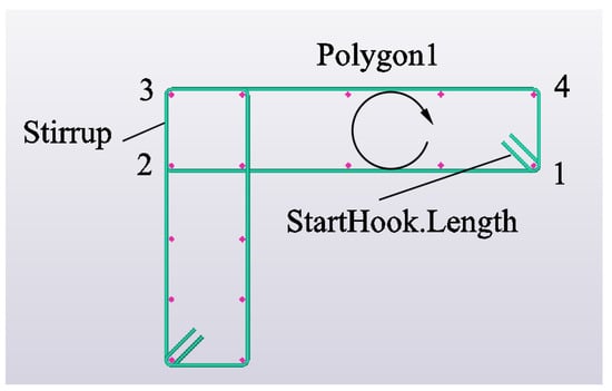
Figure 10.
Longitudinal stirrups layout plan.
The Tekla stirrup group is created by selecting the SpacingType attribute of the stirrup group object, where a value is assigned to the stirrup (spacing _ type _ accurate spacing _). Under this Spacings value attribute, the stirrup will be distributed in the plane above and below the Polygon stirrup according to the fixed spacing, finally completing the three-dimensional layout of the stirrup as shown in Figure 11 (in the model, the purple line represents the longitudinal reinforcement section, and the green line represents the stirrup section).
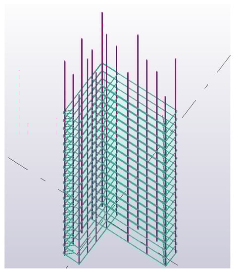
Figure 11.
Longitudinal stirrups layout 3D in Tekla.
4.5. Tie Bar Creation
The basic properties of tension and stirrup are the same, but the modeling method is different from that of stirrup creation. Figure 12 shows an idea for the stretching modeling method, which can provide modeling ideas for similar developments.
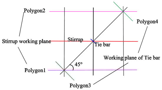
Figure 12.
Comparison of stirrup and tie bar working planes.
In Tekla, the setting of the hook direction of the tension reinforcement is realized by setting the Angle of the stirrup working plane. In the three-dimensional model, the hook direction of the tension reinforcement is generally arranged along the 45° Angle. By comparing the working planes of the stirrup and tension reinforcement, only the X values of the upper and lower working planes changed when the stirrup set was created. The points on the two planes were perpendicular lines, which meant that they were in the vertical direction, and the direction of the bending hook of the stirrup was perpendicular to the line.
In order to ensure a 45° tilt Angle in the establishment of the stretching model, 45° rotations of the corresponding points on the upper and lower planes should be satisfied. To realize this rotation Angle, the coordinate values of X and Z should be changed to form the included Angle. The working plane of the tension reinforcement obtained from this method is vertical based on the connection between two points. In this case, the Angle of the bending hook will keep a 45° direction. The stretch object is created by setting the SpacingType attribute to the exact amount of SPACING_TYPE_EXACT_NUMBER, while fixing the Spacings attribute to one. At this time, only a single tension bar can be generated between the two working planes of the tension bar, and then the steel bar can be connected to the steel bar network crossed by the longitudinal bar and the stirrup through the circular structure, the sequential structure and the selected structure statement. Figure 13 shows the creation of a stretch (in the model, the purple line represents the longitudinal reinforcement, the green line represents the hoop reinforcement, and the blue line represents the tie reinforcement).
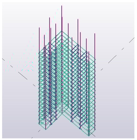
Figure 13.
Tie-bar arrangement elevation drawing in Tekla.
5. Program Application of Three-Dimensional Reinforcement of Edge Member
Based on the classification and construction requirements of edge components, this article has developed a corresponding program page, which is divided into two parts: graphic display and parameter input. Through the information prompt in the window, users can input and select the type of section, input basic information about the section, and establish a concrete model. Subsequently, users can select the diameter and specifications of the longitudinal and hoop steel bars and input the spacing between the steel bars and the thickness of the concrete cover. Finally, users can click Create to establish a three-dimensional model of the steel bars.
The edge member reinforcement modeling window application interface is shown in Figure 14.
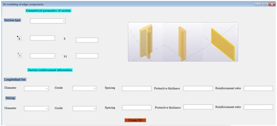
Figure 14.
Three-dimensional modeling program window of cast in situ joint area.
In practical engineering projects, cast-in-place joints of prefabricated shear wall structures, such as “linear shaped”, “T shaped” and “L shaped”, are common joint forms in engineering. The three-dimensional reinforcement deepening design model created by the program can be a good guide to the construction. The lapping and binding of reinforcing bars can also find problems in time from the three-dimensional deepening model to ensure the orderly progress of engineering construction. Through the input of section parameters and reinforcement information parameters, the three-dimensional reinforcement deepening model of cast-in-place joints of prefabricated shear wall structure can be completed. The detailed model is shown in Figure 15.
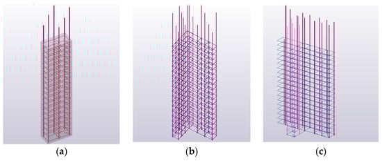
Figure 15.
Three-dimensional reinforcement model of cast in situ joints. (a) “linear-shaped”; (b) “L-shaped”; (c) “T-shaped”.
6. Case Discussion
6.1. Intelligent Rapid Modeling
According to a prefabricated shear wall structural engineering project, the three-dimensional model created is shown in Figure 16. Users configure the model and steel bar information parameters based on the program interface information. By combining the window program with Tekla, the final creation of the three-dimensional model is completed.
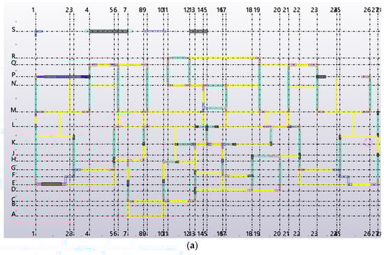
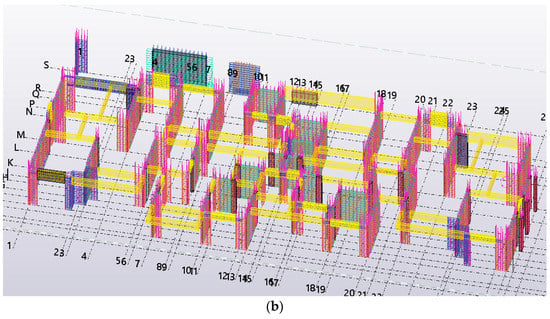
Figure 16.
Layout of reinforcement deepening model: (a) layout plan of axis 1 to axis 26; (b) 3D deepening design model.
According to the application display of the model, a three-dimensional detailed design model of the cast-in-place joint can be obtained, which can intuitively display the connection details of edge component joints. This project includes numerous conventional joints such as “I-shaped” and “L-shaped”. Taking the “L-shaped” joint in the three-dimensional model as an example, the edge component model obtained through program intelligent modeling contains precise details of the model, making the modeling process simpler and more efficient. In practical engineering applications, the arrangement of the “L-shaped” joint at the intersection of the 26 and P axes is shown in Figure 17.
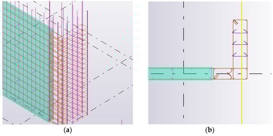
Figure 17.
Layout of “L-shaped” joint: (a) three-dimensional model of “L-shaped” joint; (b) Plan of “L-shaped” joint.
6.2. Advantages and Limitations
At present, the software that can carry out three-dimensional detailed design mainly includes Revit and Tekla. Revit is mostly used in the architectural field and has significant defects in detailed structural design. The conventional three-dimensional design software Revit can achieve three-dimensional modeling, but its method of creating steel bars is single. To create an accurate three-dimensional reinforcement model, a large number of accurate families need to be established, and due to the complex constraints of reinforcement families, variable live families cannot be created, resulting in low efficiency. Moreover, the Tekla software has comprehensive three-dimensional design functions, which can further enhance design capabilities by utilizing secondary development for in-depth application research. The comparison of design functions between Revit and Tekla is shown in Table 1.

Table 1.
Comparison of Revit and Tekla design features.
By comparing Revit with the secondary development function of the Tekla software, it can be seen that secondary development based on Tekla node modeling can achieve the goal of rapid modeling. A secondary development was carried out on the original functions of the software, and a prefabricated shear wall structure detailed design software suitable for local standards in China was developed. Compared with the constraints caused by the inflexibility of the Revit software family library, Tekla has the plasticity and the clarity of the master-slave relationship that the above software does not have (that is, the simplicity of developing document classes and objects, classes and methods, classes and attributes, which is very friendly to developers in the civil engineering industry), so it is easier to serve the development of BIM technology in the prefabricated building industry.
However, due to the limitations of the research, this article only explores the secondary development function of Tekla in a more one-sided manner. For prefabricated shear wall structures, edge components are only a part of the structure, and in practical applications, further research is needed on other parts. In the process of rapid intelligent modeling, it was found that the program page developed in this article has certain defects and cannot fully include the node features of all edge components in the structure. Within the default value range of the specification, the software can run well and quickly create the model.
7. Conclusions
(1) In this paper, the cast-in-place joint library of the prefabricated shear wall structure is developed by the BIM software, and the three-dimensional deepening design program of cast-in-place joint reinforcement is compiled. The three-dimensional program of cast-in-place joint reinforcement includes “Linear shape”, “L shape” and “T shape” cast-in-place joints, which can realize the intelligent creation of a deepening model of joint reinforcement and realize the diversification of joint modeling. Combined with the Winform program window, the corresponding program operation interface is developed to enhance the friendliness of the interactive interface. By inputting corresponding parameters through the program’s interface, the user can create a three-dimensional model of the joints. This procedure can apply the characteristics of BIM visualization, show the placement of steel bars in the cast-in-place area of edge members, and promote the development of BIM direction of prefabricated buildings to a certain extent.
(2) Using C# language for the secondary development of the Tekla Structurcs.NETAPI(), this paper describes the basic algorithm of establishing the reinforcement model and converts the obscure programming language into easy-to-understand chart text. Some ideas can also provide a reference for similar engineering developments using the means of secondary development. It improves the use efficiency of the BIM software and provides a feasible idea for the majority of construction practitioners. The reinforcement deepening modeling program developed based on Tekla can effectively solve the problem of irregular joints encountered in the modeling process, greatly improve the modeling efficiency of the Tekla software, and reduce the burden of model design for practitioners so that designers can focus on the design work and improve the design level. By deepening the direct observation of the model, it can play a certain guiding effect on the lashing construction of the cast-in-place joint area, reduce the difficulty of the operation of the construction site and improve the construction efficiency.
(3) This secondary development scheme only takes the prefabricated shear wall structure as an example to carry out the research of BIM technology, which provides a feasible scheme for intelligent modeling of components. The intelligent modeling program developed in this paper has certain limitations. There are many types of components in the prefabricated shear wall structure, and more sophisticated modeling is required for more complex components in the assembly process, such as the processing of embedded parts and avoidance problems in the structure. In addition, there are many kinds of systems for prefabricated building structures, such as prefabricated steel structures and prefabricated frame structures. The development of prefabricated building intelligent modeling should expand a variety of structural systems. The BIM software, in line with national norms, requires the joint efforts of practitioners in order to develop and further its research.
Author Contributions
Conceptualization, S.L. (Shushan Li), A.C. and W.X.; methodology, S.L. (Siyuan Li), J.H. and Y.S.; software, S.L. (Siyuan Li), J.H. and Y.S.; validation, S.L. (Siyuan Li), S.L. (Shushan Li) and H.L.; formal analysis, S.L. (Siyuan Li); investigation, W.X.; resources, S.L. (Shushan Li); data curation, S.L. (Siyuan Li) and S.L. (Shushan Li); writing—original draft preparation, S.L. (Shushan Li) and S.L. (Siyuan Li); writing—review and editing, S.L. (Shushan Li), S.L. (Siyuan Li) and H.L.; visualization, S.L. (Siyuan Li); supervision, A.C. and W.X.; project administration, S.L. (Siyuan Li); funding acquisition, A.C. and W.X. All authors have read and agreed to the published version of the manuscript.
Funding
This research was funded by the National Natural Science Foundation of China (No. U1404526, No. 52179133).
Institutional Review Board Statement
Not applicable.
Informed Consent Statement
Not applicable.
Data Availability Statement
Data are contained within the article.
Conflicts of Interest
The authors declare no conflict of interest. The funders had no role in the design of the study; in the collection, analyses, or interpretation of data; in the writing of the manuscript, or in the decision to publish the results.
References
- Feng, X. Application research of BIM technology in prefabricated building construction management. Build. Struct. 2018, 48 (Suppl. S1), 663–668. [Google Scholar] [CrossRef]
- Sampaio, A.Z.; Constantino, G.B.; Almeida, N.M. 8D BIM Model in Urban Rehabilitation Projects: Enhanced Occupational Safety for Temporary Construction Works. Appl. Sci. 2022, 12, 10577. [Google Scholar] [CrossRef]
- Famakin, I.O.; Othman, I.; Kineber, A.F.; Oke, A.E.; Olanrewaju, O.I.; Hamed, M.M.; Olayemi, T.M. Building Information Modeling Execution Drivers for Sustainable Building Developments. Sustainability 2023, 15, 3445. [Google Scholar] [CrossRef]
- Sadhu, A.; Peplinski, J.E.; Mohammadkhorasani, A.; Moreu, F. A Review of Data Management and Visualization Techniques for Structural Health Monitoring Using BIM and Virtual or Augmented Reality. J. Struct. Eng. 2023, 149, 03122006. [Google Scholar] [CrossRef]
- Alizadehsalehi, S.; Hadavi, A.; Huang, J.C. From BIM to extended reality in AEC industry. Autom. Constr. 2020, 116, 103254. [Google Scholar] [CrossRef]
- Fernández Rodríguez, J.F. Implementation of BIM Virtual Models in Industry for the Graphical Coordination of Engineering and Architecture Projects. Buildings 2023, 13, 743. [Google Scholar] [CrossRef]
- Hu, Y.; Xia, C.; Chen, J.; Gao, X. Clash context representation and change component prediction based on graph convolutional network in MEP disciplines. Adv. Eng. Inform. 2023, 55, 101896. [Google Scholar] [CrossRef]
- Wang, W. Automatic System Design of Assembly Building Components for Sustainable Building Projects Based on BIM Technology. Math. Probl. Eng. 2022, 2022, 4902862. [Google Scholar] [CrossRef]
- Zakeri, S.M.H.; Tabatabaee, S.; Ismail, S.; Mahdiyar, A.; Wahab, M.H. Developing an MCDM Model for the Benefits, Opportunities, Costs and Risks of BIM Adoption. Sustainability 2023, 15, 4035. [Google Scholar] [CrossRef]
- Ren, X. Application of prefabricated BIM technology in the whole life cycle of buildings. J. Railw. Eng. Soc. 2022, 39, 90–94. [Google Scholar]
- Gharaibeh, L.; Matarneh, S.T.; Eriksson, K.; Lantz, B. An Empirical Analysis of Barriers to Building Information Modelling (BIM) Implementation in Wood Construction Projects: Evidence from the Swedish Context. Buildings 2022, 12, 1067. [Google Scholar] [CrossRef]
- Cavalliere, C.; Dell’Osso, G.R.; Favia, F.; Lovicario, M. BIM-based assessment metrics for the functional flexibility of building designs. Autom. Constr. 2019, 107, 102925. [Google Scholar] [CrossRef]
- Forcael, E.; Puentes, C.; García-Alvarado, R.; Opazo-Vega, A.; Soto-Muñoz, J.; Moroni, G. Profile Characterization of Building Information Modeling Users. Buildings 2022, 13, 60. [Google Scholar] [CrossRef]
- Li, H.; Zhang, J.; Chang, S.; Sparkling, A. BIM-based object mapping using invariant signatures of AEC objects. Autom. Constr. 2023, 145, 104616. [Google Scholar] [CrossRef]
- Alizadehsalehi, S.; Yitmen, I. Digital twin-based progress monitoring management model through reality capture to extended reality technologies (DRX). Smart Sustain. Built Environ. 2021, 12, 200–236. [Google Scholar] [CrossRef]
- Honghong, S.; Gang, Y.; Haijiang, L.; Tian, Z.; Annan, J. Digital twin enhanced BIM to shape full life cycle digital transformation for bridge engineering. Autom. Constr. 2023, 147, 104736. [Google Scholar] [CrossRef]
- Hu, J. Deepening Design and Secondary Development of Assembled Shear Wall Structure Based on BIM; North China University of Water Resources and Electric Power: Zhengzhou, China, 2022. [Google Scholar] [CrossRef]
- Waqar, A.; Qureshi, A.H.; Alaloul, W.S. Barriers to Building Information Modeling (BIM) Deployment in Small Construction Projects: Malaysian Construction Industry. Sustainability 2023, 15, 2477. [Google Scholar] [CrossRef]
- Jiang, L.; Qiao, R.; Pan, H. Research on application problems and countermeasures of BIM technology in the whole life cycle of prefabricated buildings. Build. Struct. 2019, 49, 558–561. [Google Scholar] [CrossRef]
- Luo, M.; Chen, D. Application of BIM Technology in Prefabricated Building. In Proceedings of the International Conference on Construction and Real Estate Management, Charleston, SC, USA, 9–10 August 2018; pp. 263–270. [Google Scholar] [CrossRef]
- Wang, X.; Tang, Q.; Dong, Z.; Wang, R. Application research of BIM+ technology in prefabricated building construction management. Constr. Econ. 2021, 42, 19–24. [Google Scholar] [CrossRef]
- Xiao, Y.; Bhola, J. Design and optimization of prefabricated building system based on BIM technology. Int. J. Syst. Assur. Eng. Manag. 2021, 13, 111–120. [Google Scholar] [CrossRef]
- Li, Q.; Yang, W.; Kohler, N.; Yang, L.; Li, J.; Sun, Z.; Yu, H.; Liu, L.; Ren, J. A BIM–LCA Approach for the Whole Design Process of Green Buildings in the Chinese Context. Sustainability 2023, 15, 3629. [Google Scholar] [CrossRef]
- Razak, M.I.A.; Khoiry, M.A.; Badaruzzaman, W.H.W.; Hussain, A.H. DfMA for a Better Industrialised Building System. Buildings 2022, 12, 794. [Google Scholar] [CrossRef]
- Qi, B.; Costin, A. BIM and Ontology-Based DfMA Framework for Prefabricated Component. Buildings 2023, 13, 394. [Google Scholar] [CrossRef]
- Xu, Z.; Wang, J.; Zhu, H. A Semantic-Based Methodology to Deliver Model Views of Forward Design for Prefabricated Buildings. Buildings 2022, 12, 1158. [Google Scholar] [CrossRef]
- Li, Y.; Zhang, X.; Zhang, Y.; Qi, Z.; Yang, S. Application status and development trend analysis of BIM technology in prefabricated buildings. Eng. Technol. Res. 2022, 7, 76–78. [Google Scholar] [CrossRef]
- He, Z.-H.; Liu, T. Exploring Key Elements and Performance of BIM and VR Technologies in the Project Management of Assembled Buildings. Adv. Multimed. 2022, 2022, 1168953. [Google Scholar] [CrossRef]
- Xu, P.; Li, J.; Sun, J. Research and application of the whole process of prefabricated building construction based on BIM technology. Build. Struct. 2020, 50, 654–657. [Google Scholar] [CrossRef]
- Zhao, L.; Liu, Z.; Mbachu, J. Optimization of the supplier selection process in prefabrication using BIM. Buildings 2019, 9, 222. [Google Scholar] [CrossRef]
- Xu, Y.; Zhang, J.; Li, N.; Ao, C. BIM Model Integration of Concrete and Steel Structures in Assembled Substations; Atlantis Press: Amsterdam, The Netherlands, 2019; pp. 65–70. [Google Scholar] [CrossRef]
- Xu, Z.; Xie, Z.; Wang, X.; Niu, M. Automatic Classification and Coding of Prefabricated Components Using IFC and the Random Forest Algorithm. Buildings 2022, 12, 688. [Google Scholar] [CrossRef]
- Ben Mahmoud, B.; Lehoux, N.; Blanchet, P.; Cloutier, C. Barriers, Strategies, and Best Practices for BIM Adoption in Quebec Prefabrication Small and Medium-Sized Enterprises (SMEs). Buildings 2022, 12, 390. [Google Scholar] [CrossRef]
- Zhu, D.; Xie, J.; Huang, W.; Chen, Q. The application and research of Tekla in the deepening of prefabricated building technology. Guangdong Archit. Civ. Eng. 2017, 24, 68–72. [Google Scholar]
- Xie, H. Application of secondary development of Tekla Structures in GA diagram. Ind. Control Comput. 2018, 31, 91–92. [Google Scholar]
- Wang, D.; Hu, Y. Research on the Intelligent Construction of the Rebar Project Based on BIM. Appl. Sci. 2022, 12, 5596. [Google Scholar] [CrossRef]
- GB50011-2010; Code for Seismic Design of Buildings. China Architecture & Building Press: Beijing, China, 2016.


Disclaimer/Publisher’s Note: The statements, opinions and data contained in all publications are solely those of the individual author(s) and contributor(s) and not of MDPI and/or the editor(s). MDPI and/or the editor(s) disclaim responsibility for any injury to people or property resulting from any ideas, methods, instructions or products referred to in the content. |
© 2023 by the authors. Licensee MDPI, Basel, Switzerland. This article is an open access article distributed under the terms and conditions of the Creative Commons Attribution (CC BY) license (https://creativecommons.org/licenses/by/4.0/).