1. Introduction
Contractors are usually required to submit baseline schedules that demonstrate their intended plan for delivering projects, as well as provide periodic progress updates during the execution phase. The updates are usually provided in different forms, such as daily site reports, monthly progress reports, meeting minutes, and/or updated schedules. This information becomes part of the project contract and is generally used for resolving relevant claims. Ultimately, this scattered information is gathered and transformed into as-built schedules, which represent the actual durations and execution sequences of activities following critical path method (CPM) principles. All project changes should be considered when developing such schedules, including, but not limited to, scope, schedule, and resource allocation changes [
1,
2,
3]. As-built schedules are useful for many purposes, including verifying contractor progress on ongoing activities, project performance evaluation, claims analysis and validation, and as a reference when developing new project schedules [
4]. However, developing and analyzing as-built schedules with dynamic CPM networks is difficult for many reasons, including inadequate site event documentation [
2] and inaccurate schedule updates calculations [
5], which limit the utilization of as-built schedules when analyzing delay claims.
To develop an as-built schedule, a collection of activity progress data over time is required. More importantly, if as-built schedules are to be used for delay analysis, a history of events that took place during the project execution phase must be documented and readily available. Previous research focused on either (1) manually developing as-built schedules from unstructured project data [
1,
6] or (2) automating the as-built schedule development process [
7,
8,
9,
10,
11,
12,
13,
14]. The first approach is tedious and time consuming, because it requires a substantial effort to thoroughly review mass project documentation to sort and determine events that occurred during the project [
15], and it often suffers from inaccuracies due to lost information [
16,
17]. Moreover, a standardized process for extracting meaningful data from scattered project data is lacking, consequently resulting in a prolonged process and augmented cost. A rule of thumb in claims preparation is that 70% of the time is spent on searching for and organizing information, with the analysis processes consuming the remaining 30% [
18].
The second approach relies on the advancement of tracking technologies (digital cameras, laser scanners, and radiofrequency identification [RFID] sensors) [
13], building information models (BIMs) and smart technologies (e.g., cyber-physical systems, big data, artificial intelligence, and smart robotics) [
19]. Such technologies can be used to identify variations between actual and planned progress, so corrective measures can be taken for either schedule recovery or expenditure adjustment. Although this approach can improve the efficiency of collecting as-built data from construction sites, previous research was concentrated on progress monitoring and project controls, with as-built schedule development as a secondary focus. Additionally, adopting these new systems is an expensive process, because their application imposes new means of data collection and restricted project control tools.
This study reviews previous studies and highlights the need for a new as-built development approach. Additionally, it proposes and highlights the novel features of, a novel simulation-assisted approach to achieve (1) automated data processing, (2) integration of the impact of progress events on project schedules, and (3) assist in the development of as-built schedules. The architecture of the proposed simulation model includes two main constructs, an
entity information model that uses attributes to document relevant event data and an
entity lifecycle model that simulates the possible routes a simulation entity may take to maneuver through a schedule network in a way that responds to a predefined activity execution sequence and invokes changes to activity durations while maintaining the CPM principles. This entity-centric approach facilitates the development and analysis of as-built schedules in ways that current approaches do not. A real case study is used to demonstrate the merits of the proposed approach and validate its principles. The benefits of the newly proposed approach are also discussed, along with directions for future research. It is important to note that, while this study focuses primarily on as-built development and analysis, it is part of a larger research scope that aims to improve the overall analysis process by addressing the limitations of delay analysis techniques currently used in the construction industry [
20].
4. Simulation Architecture
This study expands on the simulation-based framework that was introduced by Fagiar, Mohamed, and AbouRizk [
20] for delay analysis. The framework takes advantage of simulation technology to model the dynamic of schedule changes as a project progresses by modeling and integrating activities changes such as durations, logic, status, start and finish dates, that are caused by unplanned events. While the framework includes delay analysis functionalities such as delay analysis and quantification algorithms, this study focuses primarily on the simulation aspects of the framework by describing the simulation architecture relevant to the development and analysis of as-built schedules.
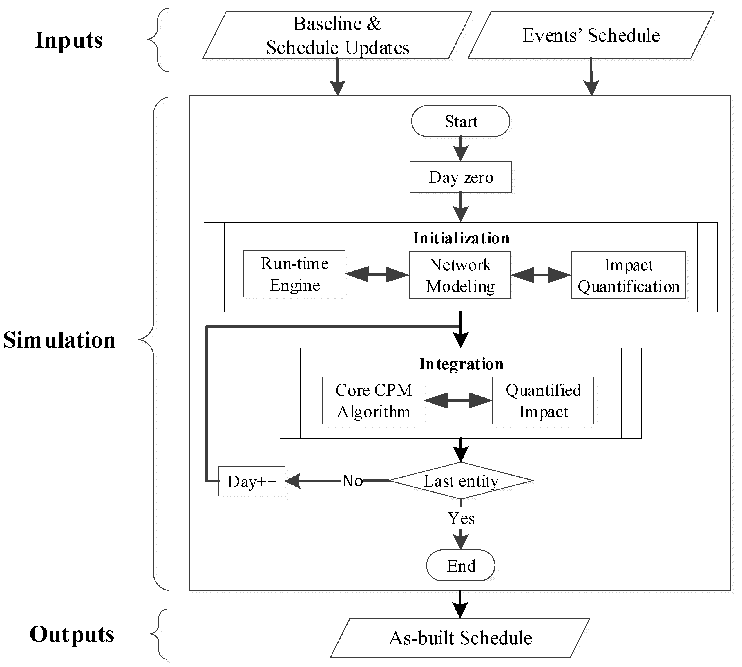
The simulation is based on the concept of time-step analysis where the analysis result of a time-step forms the basis for the successor time-step. It models the dynamics of schedule changes by extracting relative activities and their logic based on a predefined time-step of one entity, integrating the impact of events relevant to the entity instance into the CPM computation, and lastly analyzing the data to provide results. To enable this process, conceptual entities that represent time units such as minutes, hours, or weeks, are generated. It is important to note the distinction between an entity and an event. While an entity is an object with a unit of time, an event is an instantaneous incident that changes a state of the schedule and/or influences the occurrence of other events. The simulation architecture is illustrated in
Figure 1. Detailed descriptions of the proposed components are discussed as follows.
4.1. Provisions
The proposed approach relies on data from three sources, which serve as inputs: the baseline schedule, schedule updates, and the schedule of events (SoE). The proposed approach utilizes the baseline schedule as an initial reference to measure time extension or acceleration, to allocate liability, and to support the as-built versus as-planned analysis. It is also used to model the planned sequence of activities and to estimate activity duration, logical constraints, and project calendars to calculate the start and finish dates of activities as per CPM computations. The proposed approach also supports available schedule updates to reflect schedule changes. It is important that schedules used in the analysis adhere to the best scheduling practices.
The SoE is a documentation of project events that may impact the project schedule, including, but not limited to, daily site events, management decisions, change orders, and others. The proposed approach requires certain attributes of an event to be documented in a certain format, which include event ID, description, cause, quantification type (fixed, uncertain, or formula), start time, parameters, responsible part, impact type (global or task specific), as well as references and their issue dates. The reader is referred to Fagiar, Mohamed, and AbouRizk [
20] for detailed descriptions of these attributes and their formats. Transforming these inputs into the acceptable specification is based on a combination of actions from the analyst, along with automated verification and synthesis algorithms.
4.2. Simulation
Construction schedules are constantly subject to changes, depending on internal and external factors, such as planned activities, resource availability, approvals, and weather conditions. As such, a time-step simulation approach is most suitable to model the dynamics of CPM networks. It is reasonable that simulation entities may represent time units (hours, days, weeks), based on the desired level of abstraction. This poses certain modeling requirements, including (1) that each entity must be distinct and represent unique and ‘Active’ event(s) and (2) the capability to route through ‘Active’ activities, so that duration adjustments can be made where applicable. The ‘Active’ status of an event or an activity refers to the occurrence of the event or activity at that entity instance. These requirements will be addressed in the following sections through a detailed explanation of the simulation components. The entity movement is facilitated through two main constructs, (1) an entity information model that contains relevant information of events and schedule activities and (2) an entity lifecycle model that defines possible routes through which an entity can proceed through a schedule network.
4.3. Entity Information Model
Simulation entities are initiated equally by default. To make them representative of distinct time points, certain key events and activity information must be carried by the entities. This often refers to descriptive attributes such as event ID, cause, and impact. To enable entities to carry both event and activity-related information, an integrated entity information model (EIM) is designed.
Figure 2 illustrates the components of EIM, which include (1) simulation run-time data, (2) impacting events data, and (3) other project control data. The EIM is a record type where each of the fields is either a record of an attribute or collection of attributes.
As sown in
Figure 2, the EIM is broken into three categories. The
Simulation time attributes hold information about the simulation time of an entity instance, including the most current simulation timestamp as per the entity instance, cycle number, and the entity instance label (working or non-working day). The event attributes hold information about the occurrence of impacting events relevant to the entity instance, including event ID, cause, description, impact value (derived), impact type, and applicable impacted activities ID. An impact of an event on a project schedule can be expressed in three different ways, which are certain (known event duration), uncertain (uncertain event duration), and formula for events with impacts that can only be expressed formulaically. Events with uncertain impact are modeled using probability distributions such as uniform, triangular, or beta distributions. Depending on the type of events impact, the end date of each event is calculated.
A given event occurrence may be relevant to multiple entity instances; in such cases, event attributes will be recorded for all applicable entities. This means the event span is larger than an entity instance. Nesting events is supported and executed in parallel. The simulation allows both events that occur at specific times as well as periodic events to be modeled. When there are multiple events relevant to an entity instance, EIM will contain records of all events, route through all Active activities, and, accordingly, trigger change to their duration. The project control attributes are not currently implemented in this study; however, they are included to demonstrate how the EIM can be expanded to hold other information such as resources, cost, and risks.
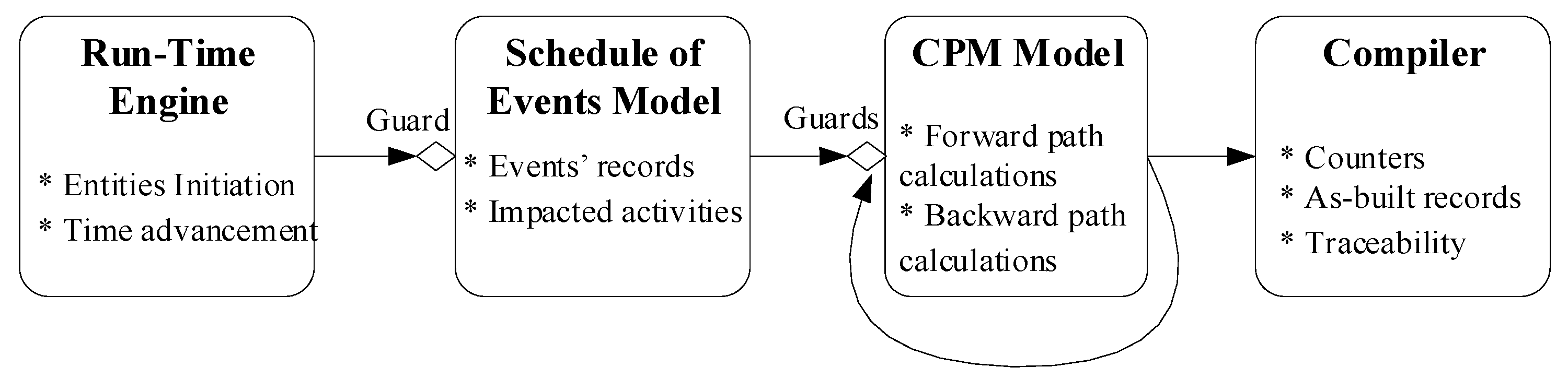
4.4. Entity Lifecycle Model
Figure 3 shows the topmost levels, referred to as stages, of the entity lifecycle. The entity lifecycle model specifies the activities that an entity can be involved in as the entity routes through its lifecycle. It is specified using stages, where each stage consists of one or more guards. A guard is a condition (possibly a triggering event) that, when activated, enables entities to route through the network model and trigger changes in the activity durations. The guard’s conditions range over the information model of the entity instance and are expressed using if/then rules. When these rules are evaluated to be TRUE (satisfying the condition under consideration), the guards become OPEN, allowing a set of associated actions (changes to activity durations) and other rules to be executed. For instance, if there was an Active Event at an entity instance, the Events’ Schedule guard would become OPEN, allowing the entity to pass through to collect records of that Active event.
4.5. Run-Time Engine (RTE)
The run-time engine (RTE) is responsible for controlling the simulation execution; creating the simulation environment; initiating entities with a timestamp, cycle number, and label—and advancing the simulation time. At time zero (τ0 = 0), the starting simulation date is initiated as the smallest early start time in the project schedule. In other words, the simulation sets the starting simulation date as the earliest start time (〖ES〗_i) of the first activity in the project. The simulated start date will then be incremented by one entity throughout the simulation of the entire schedule. Hu (2013) argued that using large time-steps results in fast but inaccurate/unstable simulations. Therefore, it is recommended to use small entity span to achieve more precise results.
4.6. Schedule of Events Model
An event can be broken into smaller events (events slicing), which are referred to as E-bites in this framework to reduce the modeling complexity of an event, thereby facilitating integration into the project activities. Event slicing transforms events into E-bites by using the entity span as slicing criteria to identify E-bites relevant to an entity instance. All E-bites inherit the attributes of their parent events. The generation of E-bites begins by defining the slicing criteria, which are the time spans represented by the entity instance. Each E-bite is tagged with a timestamp and includes a Boolean attribute, which holds its status. This is initialized at CLOSE and becomes ACTIVE once its guard becomes OPEN. The guard status changes as per the status of its parent event. For example, if an entity was released and a parent event was active, the guard becomes OPEN. This means the entity will route through the event’s schedule, and its information model will be updated as per the attributes of the parent event.
4.7. Network Model
Initial values of the activities’ attributes (ID, name, duration) embedded at compile time (τ0) are used to model the network of the project schedule. The proposed approach relies on basic CPM principles, including modeling precedence relationships, leads and lags, calendars, as well as both forward and backward passes computation through the schedule network. As schedule updates become available, they are used to update the activities’ attributes and execution logic. Modeling the aforementioned principles can be done programmatically in variety of ways, depending on preference. The modeled CPM is executed at the initiation to establish the planned project timelines. The framework supports continuous critical path identification and calculation at every time-step. It is important to note that executing the CPM at the initialization is also a vital step in verifying the modeled network.
A similar approach to event slicing is used for scheduling activities, where the durations of activities are broken down into smaller activities, referred to as A-bites. Each A-bite represents an entity span; its status attributes change as per the release of a matching entity. The Network model, however, has a guard for the network and guard for each activity. The network guard becomes OPEN once the status of a parent activity becomes ACTIVE, which allows the entity instance to route though the Network model. The activity guards become OPEN only when the network guard is OPEN, and the status of the A-bite becomes ACTIVE. In such a case, the entity routes through the parent activity and triggers changes to its duration as per the attributes of the relevant E-bites.
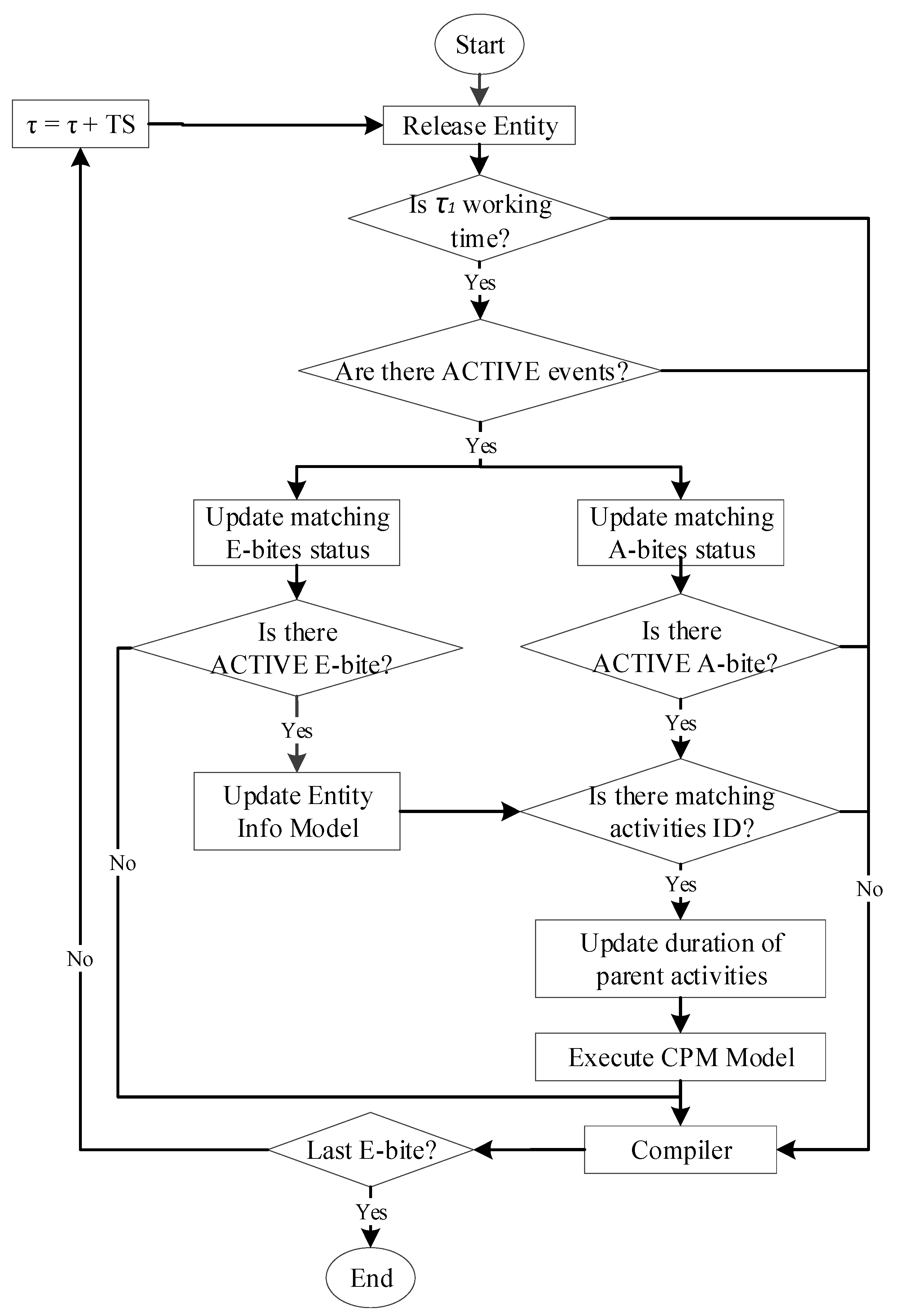
4.8. Data Integration
As shown in
Figure 4, the integration process begins by advancing the simulation time from day zero (τ
0) to the starting simulation date (τ
1). The RTE then releases the first entity instance tagged with working or non-working labels as per the project calendar. When an entity instance is released, it may result in a series of changes in the status of parent events, E-bites, parent activities, and A-bites becoming ACTIVE. Guards become OPEN or CLOSED.
When τ1 is a non-working day, the entity routes to the compiler without triggering any changes in the CPM network model; otherwise, the simulation explores the event’s schedule to determine if there is any ACTIVE event relevant to the entity instance through an event-to-event sequence. In such a case, the event’s guard becomes OPEN, allowing the entity instance to route through the event’s schedule. When there is an ACTIVE E-bite, the simulation updates the EIM; otherwise, the entity simply routes to the compiler. For ACTIVE E-bites with global impact type, the impacted activities field in the EIM will be updated to include all the ACTIVE A-bites. Additionally, for ACTIVE E-bites with a task-specific impact type, the impacted activities field in the EIM will be updated to include the ID of the impacted activities regardless of their status.
The entity instance then transfers to the network model stage. When there is an ACTIVE parent activity, the network guard becomes OPEN, allowing the entity instance to route through the network model. The activity guards become OPEN when there are ACTIVE A-bites, allowing the entity to trigger changes to the duration of parent activities as per the impact field of EIM. Durations of all Active parent activities are updated simultaneously, and the CPM model will be executed accordingly. Thereafter, the entity routes through the compiler, and the simulation advances to the next time step (TS) by following the same updating process. Thus, it shifts from one entity to the next until it passes the timestamp of the last ACTIVE E-bite. If, at any time during the simulation, a guard has a CLOSED status, the entity routes to the compiler without triggering any changes in the network model. It is important to note that an activity’s duration is only updated to a maximum of one entity span (a time-step). The update could either be positive or negative.
4.9. Outputs/Compiler
The last stage in the entity lifecycle is the compiler responsible for capturing the information recorded in each EIM, for compiling the results of the CPM, and for identifying the controlling activities at every interval. Once the simulation is complete, the compiler uses this information to generate the as-built schedule, which is a result of incorporating all of the impacting events into the durations of the base schedule’s activities. The planned and simulated timelines for each activity are recorded along with the history of the evolved events relevant to the activity. Then, a comparison of the as-built records and planned schedule of controlling and critical activities is visualized in a graphical and statistical fashion.
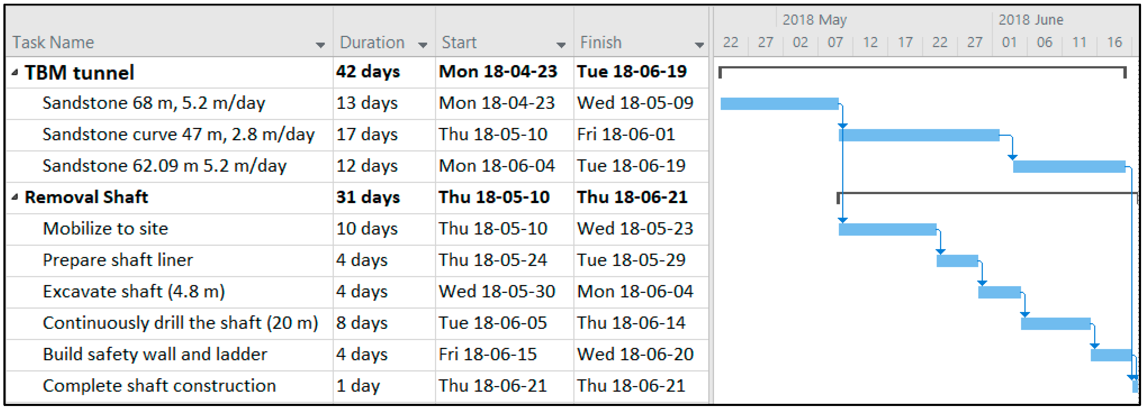
5. Case Study
5.1. Background
To verify the functionality of the framework, the prototype model was applied to a number of hypothetical case studies with various scheduling scenarios. Initial results demonstrated that the framework has several benefits due to the added features for as-built schedules. To demonstrate the observed benefits, the prototype was applied to a segment of a real-life tunneling project. The segment includes the excavation of a 162-m tunnel using a tunnel boring machine (TBM) and construction of a removal shaft. This segment was expected to be completed over 44 working days (59 days including weekends). The breakdown of activities involved in this segment and their estimated durations were defined in Microsoft (MS) Project, as shown in
Figure 5.
Another project schedule, as shown in
Figure 6, was later provided by the contractor to accommodate a TBM alignment check that took 25 days and was accepted by the owner as contemporaneous evidence providing as-built information for evaluating schedule delay and changes in the critical path.
5.2. Automated Development of As-Built Schedule
This study relied on daily progress reports and monthly progress reports that were available from the project. These contemporaneous records were organized and sorted as per the format and attributes of SoE. This process helps with organizing scattered project information, and, subsequently, enables the automatic development of as-built schedules at any time-prospectively and/or retrospectively. A concept proving prototype was developed to support scenario experiments and implementations. The prototype model uses Excel for the event schedule and MS Project for the planned schedule, as well as front-end data processing through Visual C#.Net. MS Project data was manipulated and transferred automatically to the simulation using an MPJX library. Then, the prototype of the proposed approach was used to automatically integrate the contemporaneous records with the preliminary schedule that was developed by the contractor at the start of the project. To model schedule changes, the updated schedule that was issued at a later date to accommodate the alignment check on the TBM was used. As the simulation progressed and once a schedule update became available, the schedule network, activity durations and schedule constraints were updated, while preserving analysis results, as per the schedule update.
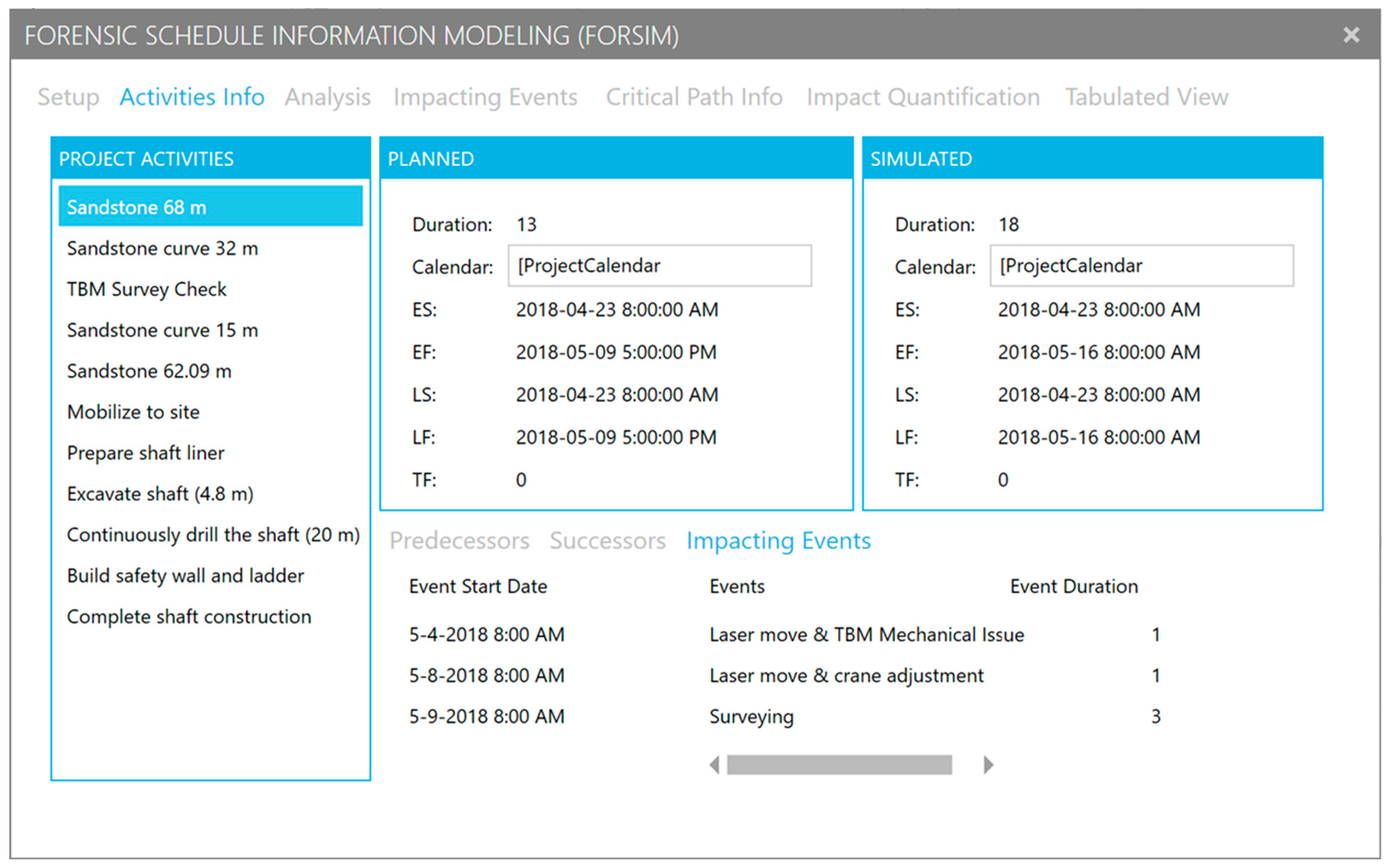
The activity information window provides a tabular view of the project activities on the left and the schedule information associated with a selected activity on the right (
Figure 7). The predecessor and successor tabs on the bottom right show the activity relationships driving the calculation, while the impacting events tab shows the events that have impacted the activity, if any. As can be noted from
Figure 7, tunneling through the first 68 m of sandstone was impacted by three events, which resulted in a five-day increase in the planned duration.
5.3. Delay Analysis Facilitation
One of the main objectives when analyzing delay claims is establishing a factual matrix and a precise chronology of events that impacted project activities and, subsequently, overall project schedule. A review of the as-built schedule provides an overall view of the delays to the project from the planned start date to the finish date. To analyze the activities of the as-built schedule, it is important to identify the critical activities that drive the schedule. However, critical activities on the last portion of the date on which the schedule status is being reported (data date) cannot be identified through the use of conventional scheduling tools. Consequently, the driving activities of an as-built schedule are called controlling activities and are identified either through the baseline schedule or schedule updates. In the absence of schedule updates, the identification of controlling activities becomes a subjective process that is based on the opinion of project participants. In such cases, the proposed approach uses the simulation traceability feature to track and demonstrate controlling activities of completed work based on a predefined total float specified by the user or analyst, or through the calculation of the lowest total float during the simulation of the entity instance.
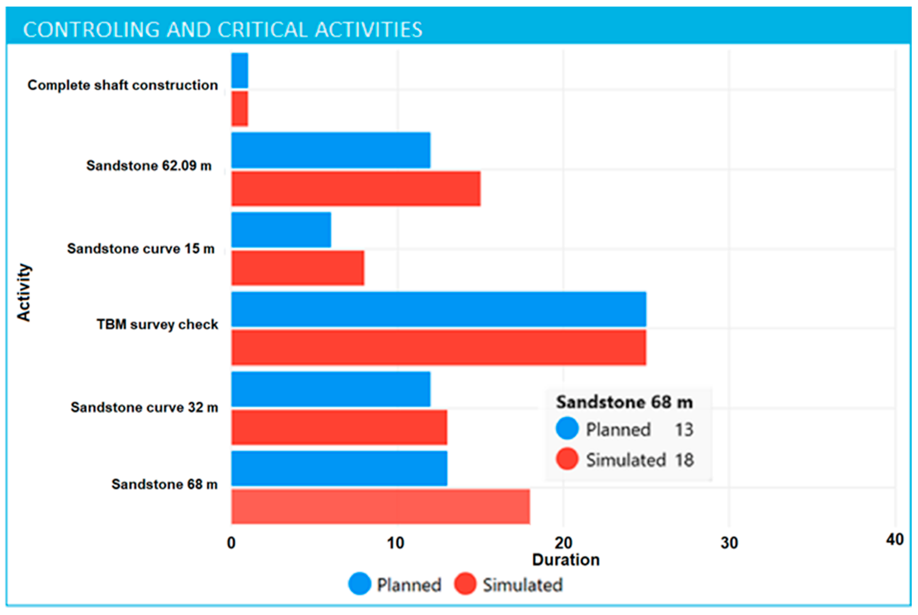
Figure 8 illustrates bar charts for controlling and critical activities at the time of analysis. For each activity, the planned duration and simulated duration are plotted with blue and red bars, respectively. Details of the planned duration and simulated duration of an activity can be observed by hovering a cursor over the desired activity bars. This helps analysts identify and isolate controlling activities with large delays and allows for more focused delay analysis.
One form of analysis is based on an as-planned versus as-built schedule delay analysis method. It is a retrospective approach used to compare the baseline, or as-planned, construction schedule against the as-built schedule. The as-built schedule reflects the progress of all activities and milestones throughout the project and provides verification of the driving activities of the schedule. The proposed approach facilitates as-built vs. as-planned analysis by automatically providing activity information (planned and actual dates), thereby identifying controlling and critical activities, along with a detailed documentation of events that impacted activity progress, in one way or another.
Some of the other observed benefits of the proposed approach to as-built schedule development and analysis include:
The method takes into account the uncertainty of event timelines. Previous studies show that the data capturing process is subject to human errors, the unavailability of contemporaneous records, and conflicting information regarding the progress of an activity due to inaccuracies and inconsistencies between the contemporaneous records available for a project. More specifically, in this case study, some daily site reports were not available because they were never sent, or, in some instances, the wrong reports were sent (for instance, the report of the previous date was sent a second time, resulting in duplicate reports). This negligence resulted in uncertainty with the timelines used when developing the event schedule. For these cases, the proposed framework enables the use of distributions to model timelines uncertainties; for this case study, uniform distributions were used.
The method limits the level of scheduling skills required for the development of as-built schedules. Developing realistic as-built schedules requires experienced schedulers to review project documentation and establish the activity execution sequence. The current system eliminates this subjective process and, in contrast, helps inexperienced schedulers have a better understanding of projects.
The proposed method limits the need for balancing between purpose of analysis and as-built schedule preparation cost. Typically, delay analysts are constrained by the need to strike a balance between the objective of the analysis and the cost of preparing an as-built schedule. For instance, in the case of retrospective delay analysis, the time required to identify the start and finish dates for all activities on a large schedule is disproportionate in terms of the cost and time required, especially when delay events impacted a small portion of the activities. Practically, therefore, analysts compromise by collapsing activities that are pertinent to the analysis process into a single activity or bar when illustrating as-built schedules. When such a balance is made, analysts are required to demonstrate that the omission of identifying actual dates of non-critical work was not intentional to avoid contradictory or negative evidence that does not support the conclusion of the analysis. On the contrary, the proposed framework eliminates the need of this subjective and judgmental balancing process by enabling analysts to focus on identifying the actual dates of events that might have impacted the project schedule, rather than wasting effort to identify actual dates for all activities.
The proposed method offers a more objective approach to as-built development: Traditionally, as-built schedules are created either from scratch or a fully progressed schedule update and are then modified or augmented as needed. Both approaches require analyst interaction with the schedule, which makes the development process subjective and easy to manipulate. The proposed framework eliminates any interaction with the schedule by fully progressing the planned/baseline schedule and schedule updates, when available, with contemporaneous records, while simultaneously modeling the dynamics of schedule changes.
5.4. Results Validation
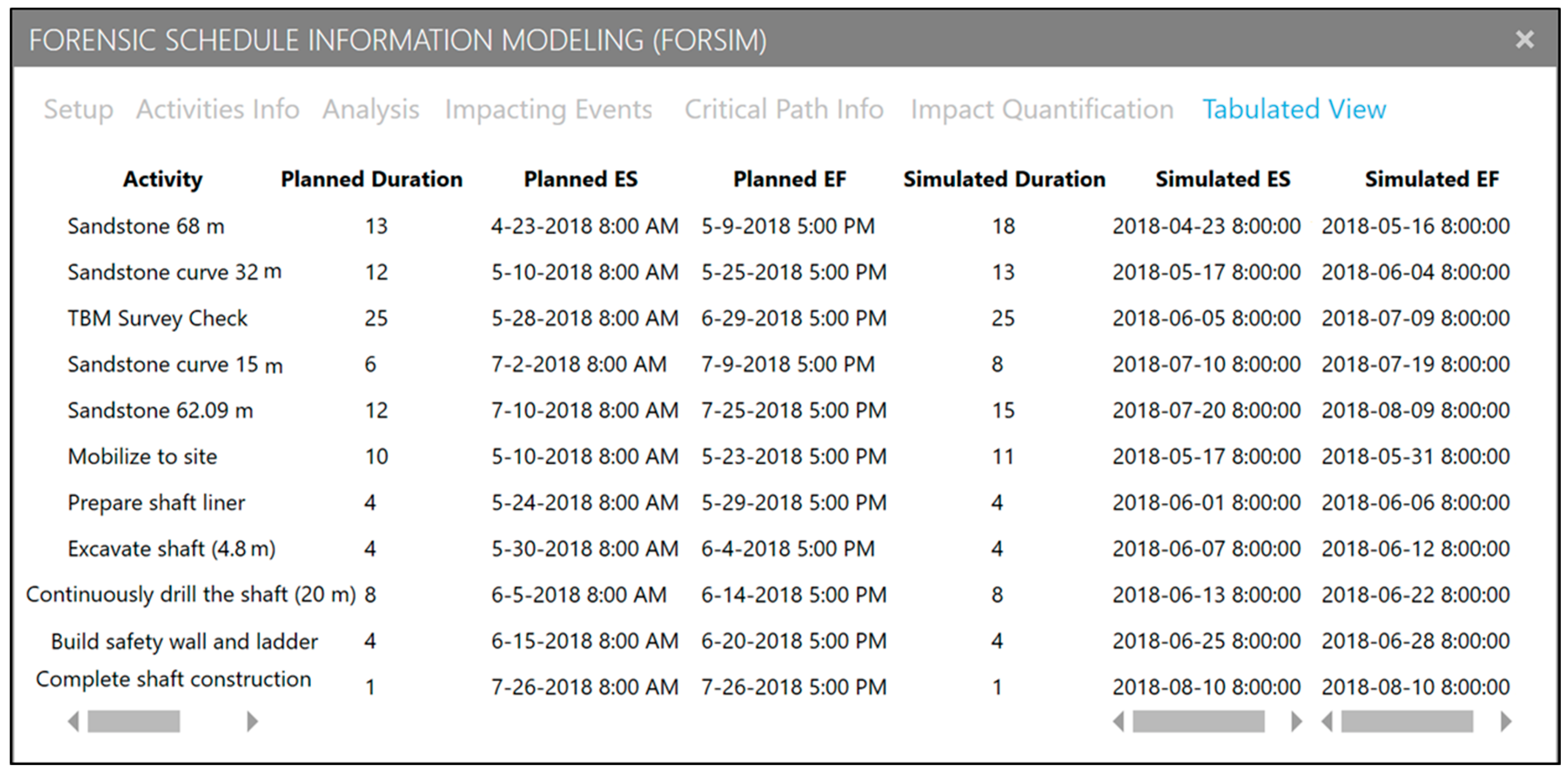
To validate results, a comparison between the simulated planned dates with those of the baseline schedule and schedule update were drawn. The tabulated view window, as shown in
Figure 9, provides a tabular view of tunneling segment activities, reflecting both the simulated project plans and as-built records. The timelines of the “Sandstone 68 m” activity, as well as the planned early start date of “Sandstone curve 32 m” activity, are matched with those indicated in the baseline schedule (
Figure 5) primarily because the simulation model was initially based on the baseline schedule. Once the schedule update became available, the network model was updated to reflect schedule changes (TBM alignment check). Consequently, the timelines of the remaining activities are matched with those indicated in the updated schedule (
Figure 6).
Moreover, the simulated as-built timelines can be validated at an activity-level by comparing event information with simulated timelines. As it can be noticed in
Figure 7, some of the planned activity durations changed after the simulation and integration of event(s) that impacted the activities and resulted in extension to the planned completion dates. For instance, the “Sandstone 68 m” activity, as shown in
Figure 7, was impacted by three events that contributed a total of 5 days of delay to its planned completion date. It is also noticeable that the durations of un-impacted activities remained unchanged, while the start and finish timelines were automatically updated based on the modeled CPM calculation. In general, increase in activities durations indicate delay while decrease in activities durations indicate acceleration. These comparisons show that the proposed approach can successfully generate as-built schedules. It also provides schedule analysts with information needed to better understand project execution. It is important to note that the prototype is currently limited to one calendar per schedule due to technical difficulties with the MPJX library, which can easily be addressed in future implementation and development.
6. Conclusions
The role of as-built schedules in claims analysis cannot be underestimated. While existing methods for as-built schedule development have been gradually improving in terms of data capture efficiency, automation of schedule generation, and visualization, the existing methods limit the usefulness of as-built schedules, prolong the development process, and increase cost. Previous studies also fail, collectively, to provide desired features of as-built schedules, which would ultimately add to their value in claims analysis. This study introduced a simulation architecture to automatically develop as-built schedules that are specifically tailored to facilitate the delay analysis process. The simulation approach enables an efficient data integration process and adds valuable features to as-built schedules, such as event traceability, data organization, and uncertainty modeling. Due to the importance of these features in delay analysis, having them as mandatory requirements in claims submission is long overdue. In this method, as-built schedules can be developed either prospectively or retrospectively with limited scheduling knowledge and expertise. The proposed data structure for the schedule of events is simple, logical, and helps project teams to organize project data in a manner that is useful for many project management functions. Additionally, the modeling approach is flexible and can easily be adopted for modeling other complex construction operations. A prototype model was also developed, and real project data were used to demonstrate framework capabilities and for validation purposes.
This study showed that simulation technology and principles can be beneficial in integrating and analyzing project data including schedule updates. As the present study served as a proof-of-concept, expansion to the framework to cover the delay analysis process will be explored in future studies. This expansion includes a delay analysis mechanism, events categorization, liability allocation, and integration of model-based impact quantification.


