Article

Automatic Generation Construction Shop Design Model of the MEP Hanger Based on BIM

1
Pusheng Zhilian (Shandong) Safety Technology Co., Ltd., Weifang 262500, China
2
The Third Construction Co., Ltd. of China Construction Eighth Engineering Division, Xuzhou 221100, China
3
Suzhou Hoogo Construction Buxiliary Co., Ltd., Suzhou 215100, China
4
School of Mechanics and Civil Engineering, China University of Mining and Technology, Xuzhou 221116, China
*
Author to whom correspondence should be addressed.
Buildings 2023, 13(4), 867; https://doi.org/10.3390/buildings13040867
Submission received: 21 February 2023 / Revised: 24 March 2023 / Accepted: 25 March 2023 / Published: 26 March 2023
(This article belongs to the Special Issue Intelligent and Computer Technologies Application in Construction II)

Abstract

:
Due to the growing complexity of mechanical, electrical and plumbing (MEP) functions, the design, production and installation of hanger based on MEP has become low efficiency in traditional ways. Compared with the Computer-Aided Design (CAD) approach, the MEP hanger three-dimensional (3D) design approach has not received adequate attention in the process of engineering practice. Based on Building Information Modeling (BIM) and Revit secondary development technology, an automatic generation construction shop design model system of MEP hanger (MEP hanger-CDM) for the quick placement of hanger components, automatic grouping of hanger components and hanger component constructability checking was developed. By conducting investigations with the construction companies and construction sites in China, four basic forms of MEP hanger layouts were identified to accommodate different types of MEP layouts. In addition, the design requirements of the family of LOD 400 BIM models were summarized along with the analysis of user requirements. The results of the case studies indicate a 70% reduction in the manpower number on the MEP hanger shop design and an 85.9% reduction in the number of working hours. Moreover, the efficiency of the hanger construction model design and the accuracy of the output of material lists and shop drawings could be improved. Thus, the process of designing MEP hanger could be optimized in a visualized method.

1. Introduction

Currently, the demand for architectural features has risen due to advances in technology and improved design standards [1]. As a result, building designs are more complicated than ever, especially in the MEP system [2]. The MEP system consists of different subsystems, including mechanical ducts, plumbing pipes and electrical cable trays. There are a variety of design codes for MEP systems, which are considered in the detailed design of the construction and could lead to cross-collisions between ducts, pipes and cable trays, especially in intensive spaces where the MEP components are dense [3]. Moreover, compared to other common domains, MEP components are not only numerous and diverse, but also have more complex structural forms [4]. In the construction phase, the MEP hanger is the first step and a critical factor for the quality and efficiency of the MEP system. The shop drawings of MEP hanger were mainly produced manually by using 2D designs of CAD tools, meanwhile most studies in the field of construction model design only focused on CAD working patterns [5]. In CAD mode, the position and arrangement information of the components in the MEP system are displayed as a 2D drawing; meanwhile, the spatial information between the components needs to be explicitly stated, which makes the implementation of the MEP hanger construction model design challenging [6]. Therefore, it is easy to make shop drawings of MEP hangers incorrect, and various construction problems, such as reworks, time delays and overcost, may occur [7,8]. BIM technology is an important part in the process of digital architecture and plays a vital role in the construction industry [9]. The application of BIM could enable the representation of the building systems in 3D and facilitate the exchange of information in a digital format [10]. In contrast to CAD, BIM is not only designed for 3D visualization but, more importantly, BIM brings together the benefits of interoperability, information integration, and conflict reduction [11,12].
The efficiency of design process of shop drawing could be improved significantly by using BIM technology. In China, BIM application for the construction industry is extensive in quantity, wide in scope, but low level in the localization of BIM [13,14]. Liu et al. (2021) combing with the Chinese code for construction of masonry structures engineering (GB 50924–2014), examined the effects of the localization of BIM on the design of a masonry structure [15]. Wang et al. (2022) proposing the deployment framework to offer a handy tool for executives to localize BIM [16]. The BIM-based program allowed for the integration of construction information on a reliable and extractable 3D mode with various components of the project, which supports improvements in the automation and compatibility of the phases [17]. The application of BIM plug-in could effectively facilitate the development of BIM localization, as well as improve productivity and optimize the design process.
The construction shop design model should be designed by conducting high-precision model families. Currently, the extension of the component family is difficult to achieve due to the lack of unified design standard. In addition to this, systematic research about the construction shop design model in the LOD 400 BIM model is still lacking [18]. BIM applications in MEP usually end after the completion of a coordinated or engineering design based on the LOD 300 BIM model in China [19]. MEP hanger construction shop design models tend to rely more on the LOD 400 BIM model than other designs, as the LOD 200 to 300 BIM models typically do not contain additional detail information in their construction [20]. According to the requirement of LOD 400, the BIM model included items such as support and connection [21], which can be directly handed over to suppliers to manufacture [22]. Therefore, MEP hanger construction shop design models, which are created by using LOD 400 can only be conducted and examined in high-precision model families with the spatial and property information.
The application of BIM techniques requires an efficient method to support its implementation. Currently, these methods have been explored in some aspects of engineering practice. For instance, Khahro et al. (2021) studied and presented insights into the efficient use of energy in the building sector and demonstrated the result in different parameters and components through a case study [23]. Yilmaz et al. (2023) developed the Building Information Modelling Capability Assessment Reference Model (BIM-CAREM) and proved its usability through multiple explanatory case studies [24]. Liu and Shi (2017) established a KanBIM quality control (QC) system based on BIM and lean theory, and realized a more efficient QC process by analyzing the tools and techniques required by the system [25]. Leite et al. (2011) evaluated the modeling effort associated with generating building information modeling at different levels of detail (LoD) and the impact of LoD in projects in supporting mechanical, electrical and plumbing design coordination [26]. However, few studies have been conducted on MEP hanger design based on BIM, which is an effective approach for coordinating construction shop design model in the complex MEP system.
Compared with 2D design mode, the 3D design mode using Revit tools can clearly express the complex spatial relationship of components, which makes it possible to design the MEP hanger with a complex MEP structure [27,28]. Traditionally, the design and construction of MEP hangers basically relied on the limited expert experience since there was no accessible information that could be applied by engineers to make the logical choice between established and innovative design options [29]. The 2D design mode for MEP hanger using CAD tools can only satisfy the design requirements of MEP structures in the office building without any complex spatial location relationships, and the spatial location information of components can be expressed by 2D plans [30]. Furthermore, buildings with complex functions such as subway stations make it a great challenge for designers to express complex 3D spatial location information through 2D design mode [31]. Even with the support of BIM software, the MEP hanger layout model is created manually, which does not improve the design efficiency. Most importantly, the creation, inspection and modification of MEP hanger models involved a large amount of repetitive work, which can be replaced by the programs that are based on specific algorithms; thus, the efficiency could be improved to a large extent instead of using manual BIM work [32]. However, the complexity of the MEP hanger forms makes it difficult to carry out the design work within a specific procedure [33]. Additionally, the relevant standards of MEP involving several professions are complex and various. The information integration of each component (Duct, Cable Tray, Pipe) in the MEP system is inefficient for manual operation [34]. The construction feasibility is determined by design rationality, which could not be satisfied by the third-party automatic rationality inspection. It is believed that it takes more time by using manual operation to modify the information of the model [35]. Furthermore, the material lists and shop drawings could not be exported easily by applying traditional ways. Therefore, it is essential to study the MEP hanger project and construct a system that can meet most of the design requirements [36].
For this purpose, a survey of MEP hanger projects in China was conducted as well as an exhaustive analysis, which focused on the forms of MEP hanger in the project was investigated. In addition, four basic forms of MEP hangers were derived. It could be concluded that 85% of the MEP hanger design requirements could be satisfied by using the basic forms alone or in combination. Then, the high-precision model family was designed in order to meet the requirements of the LOD 400 BIM model. The design requirements of model family were summarized to improve the applicability of Revit plug-in by promoting the extensibility of model family files. The algorithms for the quick placement of hanger components, the automatic grouping of hanger components and hanger component constructability checking were designed, which could improve the efficiency and feasibility of the construction shop design model. Finally, a BIM-based mechanical and electrical equipment hanger construction shop design model and software were developed by combining with the Revit secondary development technology.
There are two primary aims of this study: (1) To investigate the forms of MEP hanger and serve for the localization BIM application of the MEP hanger project in China; (2) To ascertain and optimize development process of the Revit plug-in, in order to improve the constructability of MEP hanger design in Revit. In this paper, the methodology of this study, which demonstrates the implementation of the construction shop design model system is displayed in Section 2. The detailed implementation process of the MEP hanger-CDM is revealed in Section 3. Three case studies are illustrated in Section 4. Then, a conclusion of the contributions and limitations is presented in Section 5.

2. Methodology

2.1. Research Framework

This study aims to implement a BIM-based construction model design for MEP hangers by integrating Revit secondary development technology with the basic forms of MEP hanger layout. Figure 1 illustrates the general framework created in this study, including the following three steps.
  • Establish a BIM model to provide primary data information for the construction design model by using Revit (the software developed by AutodeskTM (San Rafael, CA, USA));
  • Identify the forms of MEP hangers and create the families of MEP hangers through the collaboration of the User, System Developer and Family Designer;
  • Develop an MEP hanger-CDM system by using Revit secondary development technology. This system mainly consists of three modules: quick placement of hanger components, automatic grouping of hanger components, hanger component constructability checking and modify. This system is equipped with one type of data extraction: extracting information from the BIM model using API.
This study proceeds around the implementation of the MEP hanger-CDM system.
Figure 1. The framework of this study.
Buildings 13 00867 g001

2.2. Preparation for MEP Hanger-CDM System

The MEP hanger structure consists of several components, each of which performs a different function. The base is fixed to the bottom of the floor or cross-arm. The column is attached to the base. The cross-arm is connected to the column by the connector. The process of preparation was as follows: (1) The exhaust algorithm was applied to analyze the possible forms of MEP hangers in the project to identify the basic forms of MEP hangers; (2) The family of LOD 400 models was conducted, then the design requirements for the families were summarized.

2.3. Quick Placement of MEP Hanger Components

In order to simplify complex problems and to achieve D&C (divide-and-conquer algorithms), the forms of MEP hangers were analyzed. The Revit secondary development technology was applied to assist the users to place MEP hanger components on the BIM platform efficiently, as well as to improve the flexibility and convenience of the design while comparing to the pre-written programs with fixed methods. Thus, the UI interfaces were developed by dividing a function into four sub-functions, which can be used individually or in combination.
Automatic grouping of hanger components is performed after the quick placement of hanger components to prepare the constructability inspection of the hanger members.

2.4. Hanger Component Constructability Inspection

The hanger component constructability inspection includes the following two aspects:
  • The quantity relationship of component examination. The components in the group are extracted for collision checking and the results are analyzed by formulating the check logic based on the connectivity properties of the hanger components;
  • Component reasonableness checking. Check whether the arrangement of the hanger meets the construction requirements or not; if not, the system provides a modification solution.
Compared with third-party compliance checking software based on IFC models, the plug-in based on the BIM platform makes it possible for users to identify non-compliant designs during the design process without having to modify them afterward, thereby the design process could be optimised.

3. Implementation of the MEP Hanger-CDM System

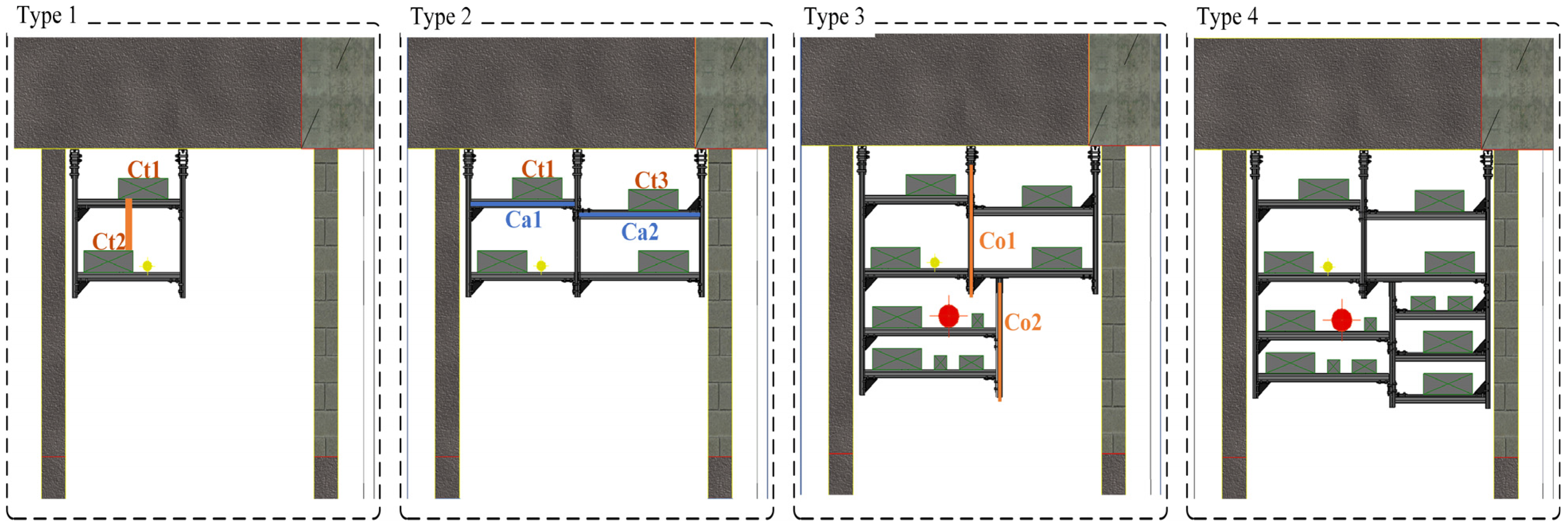
3.1. Identifying the Basic Forms of MEP Hanger

In this study, the local construction companies and construction sites in China were investigated, the exhaust algorithm was selected to analyze the possible forms of MEP hangers, the numerous forms of MEP hangers are analyzed to identify the basic forms of MEP hanger layout.
As shown in Figure 2, the hangers contain four basic forms in the project. Form 1 consists of two columns, two bases, several cross-arms and connectors, while Form 2 consists of one column, one base, several cross-arms and connectors on the side of the existing hanger. Compared to Forms 1 and 2, Forms 3 and 4 are more complicated. Form 3 consists of an extension part of the upper column, one column, one base, a number of cross-arms and connectors, while Form 4 consists of an extension part of the upper column, several cross-arms and connectors.
Uncertain types of MEP hangers lead to variable combinatorial forms. In this study, MEP hangers are divided into two categories by differentiating the main body of the base: (1) Hangers with base fixed to the floor; (2) Hangers with base fixed to the cross-arm. Thus, the modeling methods that are applicable to Revit from four forms of MEP hangers and the modeling methods were summarized as follows:
  • Modeling method 1 for double columns with bases fixed to the floor;
  • Modeling method 2 for a single column with bases fixed to the floor;
  • Modeling method 3 for a single column with a base fixed to the cross-arm;
  • Modeling method 4 for no column.
Figure 3 shows a schematic diagram of the modeling methods in the section view. If the heights of the bottom of the horizontal pipes are the same, and the height difference between the vertical pipes (the vertical distance between the bottom of Ct1 and the top of Ct2) is greater than the height of the cross-arm, modeling method 1 is used in Type 1. Type 2 shows an alternative situation. Modeling method 2 is used when the height of the bottom between Ct1 and Ct3 is unequal and two cross-arms are needed to support Ct1 and Ct3. In Type 3, modeling method 3 is chosen when column (Co1) cannot be extended downward due to the constraint of the lower pipes, and column (Co2) needs to be supplemented in the lower part of the cross-arm. The application scenario for modeling method 4 is complementary to method 3, showing another hanger erection method.

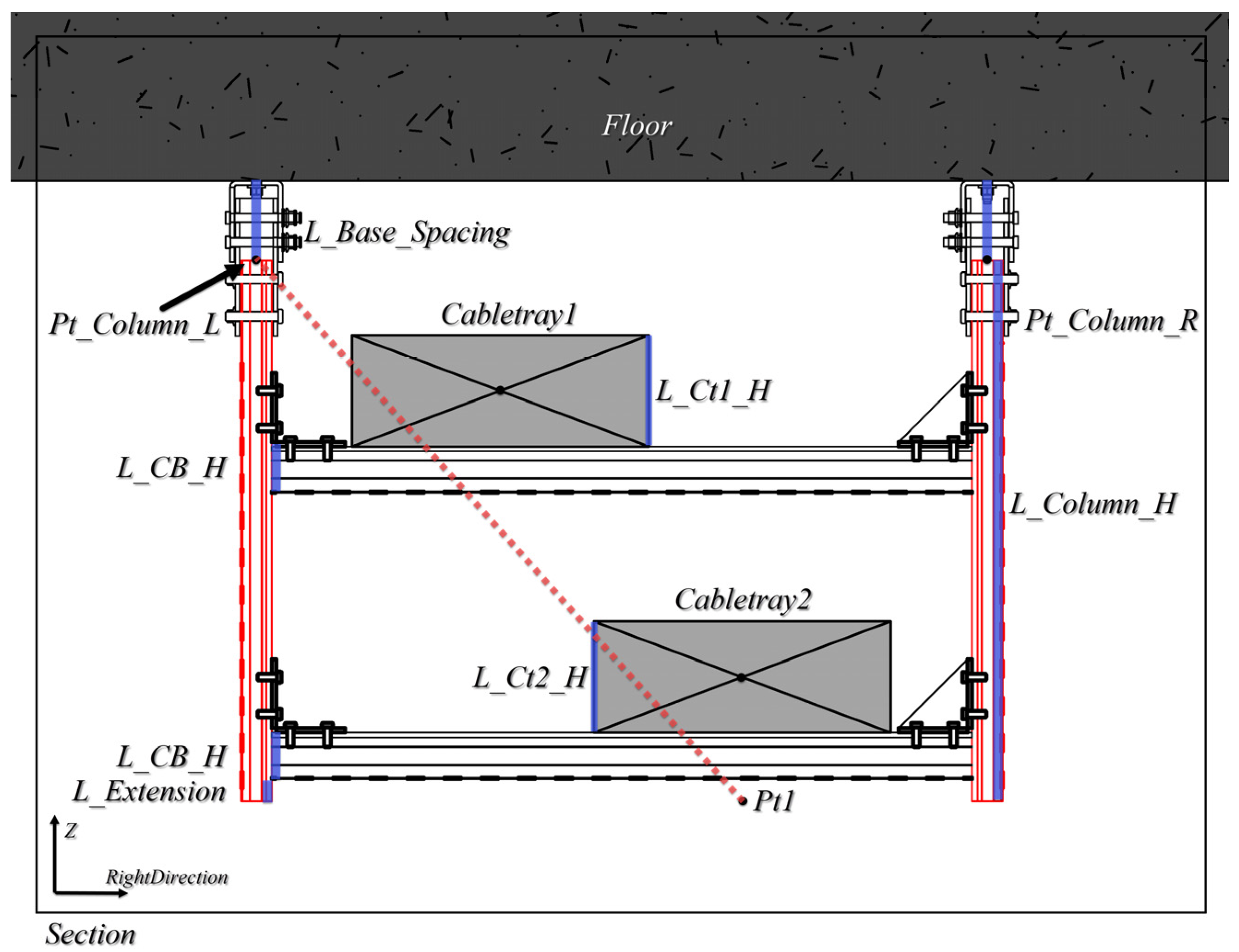
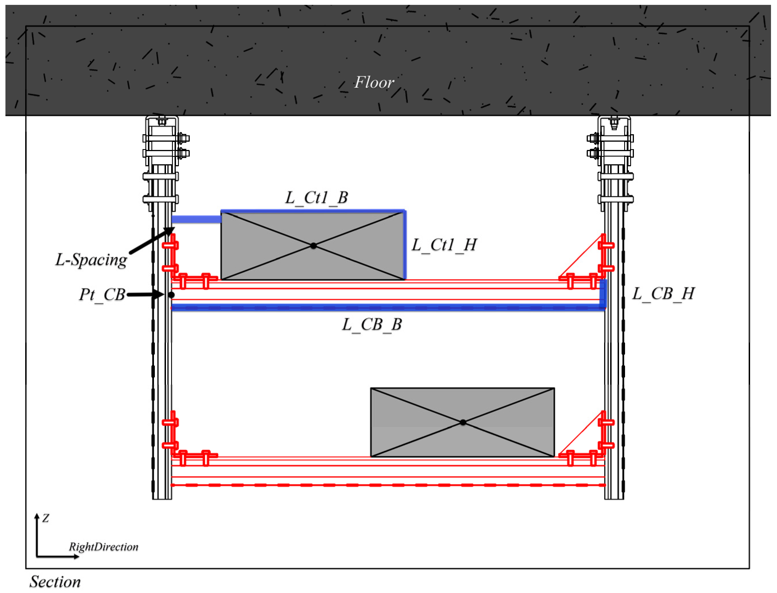
3.2. Creating the Families of MEP Hanger Components

The base of the MEP hangers is fixed to the bottom of the floor (cross-arm), and the connector connects the column to the cross-arm. Families of bases, connectors, cross-arms and columns were created in Revit in conjunction with the component design parameters of the MEP. In the design phase of the family, the family properties and “family parameters” are set according to the usage of the family and the connection relationship between the family instances. Figure 4 illustrates the design criteria for families which are determined by the application of families and the connection relationship between the family instances.
Figure 5 reveals the different family models of hanger components. After setting the “Family Parameters” of the base family to “Always vertical”, the family instance could be rotated along the Z-axis. The family-type parameter “Column vertical offset distance” simplified the calculation process of the connected column coordinates. For columns, the “Family Parameters” of the column family are the same as those of the base fam. Nevertheless, the setup of the cross-arm differs from the above two components. The “column width” is added to the family-type parameter in order to simplify the calculation process of the coordinates of the cross-arm to which it is connected. Additionally, the “Work Plane-Based” option in the “Family Parameters” of the cross-arm was selected to rotate the family instance of the cross-arm along a line perpendicular to the Z-axis. Then, the family-type parameter “Height of cross-arm” was set, by which the calculation process of the coordinates of the connector can be simplified. The “Family Parameters” of the connector family’s settings are the same as those for the cross-arm.

3.3. Secondary Development for Quick Placement of MEP Hanger Components

The BIM model provides the information that is needed for the calculation by locating the placement of components with spatial coordinates. However, the carriers of such information (architecture models, MEP models, and section view objects) are freely distributed in the BIM model; therefore, it is necessary to analyze how to extract and process model information.
Visual Studio 2022 is a platform for compiling and debugging. As shown in Figure 6, the method of invocation in the Revit API is determined by the design criteria for component features and families. Module 1 is used to implement modeling method 1. Module 2 (Implementing modeling method 2) is used in combination with Module 1. Module 3 (Implementing modeling method 3) is used in combination with Module 1 or 2. Module 4 (Implementing modeling method 4) is based on Module 3.
The determination of space coordinates and rotation radians of components is the premise of the quick layout system. The complex spatial relationships are a feature of the MEP hanger model, and it is more challenging to calculate the spatial coordinates of components through the MEP and architecture model. Section objects in Revit contain a lot of information, such as RightDirection, which helps system developers calculate the spatial coordinates of the components. Therefore, this paper calculates the coordinates from the MEP model, architecture model and section object information, and creates the MEP hanger model by the coordinate information and the overload method NewFamilyInstance(location, symbol, structuralType) in Revit API.
The implementation of Model method 1 was taken as an example to introduce the coordinate calculation and method calling process of the hanger component.
First of all, the position coordinates of the base instance at the bottom of the floor were calculated as shown in Figure 7. The figure shows the section view of the MEP hanger model that was created in Revit. The variable L_Spacing is the distance between the cable tray and the column. The variables L_Ct1_B and L_Ct2_B are obtained by extracting the properties of the cable trays, which are the width of the cable trays. The variables Pt_Cabletray_1(x, y, z) and Pt_Cabletray_2(x, y, z) are the intersections of the centerline of the cable tray and the surface of the section view, which were calculated by the centerline and the plane equation. The variable BoundingBox of the floor is applied to calculate the Z values of variables Pt_Base_L(x, y, z) and Pt_Base_R(x, y, z). The variables L_Width_1 and L_Width_2 are collected by extracting the parameter “column width” of the column family. The variable RightDirection(x, y, z) is the property of the section view. Then, the coordinates of X, Y, and Z of Pt_Base_L(x, y, z) could be calculated as follows:
P t _ 1 = P t _ C a b l e t r a y _ 1 R i g h t D i r e c t i o n · L _ C t 1 _ B 2 + L _ w i d t h _ 1 2 + L _ S p a c i n g
P t _ B a s e _ L   =   ( X   o f   P t _ 1 ,   Y   o f   P t _ 1 ,   Z   o f   B o u n d i n g B o x . M i n )
Similarly, the coordinates of the Pt_Base_R(x, y, z) can also be calculated in this way.
By extracting the properties Origin1(xo1, yo1, zo1) and ViewDirection1(xv, yv, zv) of the section view, Origin1 as the origin of coordinates of the section view and ViewDirection1 as the normal vector of the section view could be obtained. By extracting the properties Origin2(xo2, yo2, zo2) and Direction(xd, yd, zd) of the cable tray, Origin2 as the origin of the cable tray and Direction as the direction vector of the cable tray could be acquired. Then, the X, Y, and Z coordinates of the Pt_Cabletray_1(x, y, z) on the cable tray could be calculated as follows:
x v ( x - x o 1 ) + y v ( y - y o 1 ) + z v ( z - z o 1 ) = 0
x = x o 2 + t x d y = y o 2 + t y d z = z o 2 + t z d
The coordinate of the Pt_Cabletray_2(x, y, z) can also be calculated in the same way.
The placement direction of the base instance is the default, which needs to be rotated along the Z-axis in Revit. Thus the NewFamilyInstance(location, symbol, structuralType) was chosen to create the base family instance; meanwhile, the RotateElement(document, elementToRotate, axis, angle) was chosen to rotate the base instance in order to adjust the position and orientation of the family instance so that it is properly placed. The parameter angle(radian) is the rotation radian of the base, obtained by calculating the cosine value of the vectors RightDirection(x, y, z) and XYZ.BasisX(x, y, z).
Next, the position coordinates and lengths of the column instance are calculated as shown in Figure 8. The figure shows the variables that are used to calculate the position coordinates, which are Pt_Column_L(x, y, z), Pt_Column_R(x, y, z) and the column length L_Column_H. The variable L_Base_Spacing is obtained by extracting the parameter “Column vertical offset distance” of the base family, in order to calculate the position coordinates. The variables L_Ct1_H and L_Ct2_H are the heights of the cable tray family instance. The variable L_CB_H is the height of the cross-arm, which is obtained by extracting the parameter “Height of cross-arm” of the cross-arm family. The variable L-Extension is the extended length of the column. Then, the X, Y, and Z coordinates of the Pt_Column_L(x, y, z) and value of the L_column_H could be calculated as follows:
P t _ C o l u m n _ L = P t _ B a s e _ L - L _ B a s e _ S p a c i n g · X Y Z . B a s i s Z
P t 1 = P t _ C a b l e t r a y _ 2 X Y Z . B a s i s Z · L _ C t 2 _ H 2 + L _ C B _ H + L _ E x t e n x i o n
v 3 = P t 1 P t _ C o l u m n _ L
L _ C o l u m n _ H = v 3 · X Y Z . B a s i s Z X Y Z . B a s i s Z 2 v 3
The coordinate of the Pt_Column_R can also be calculated in the same way.
The column instances are created and rotated in the same way as the base instances.
Thirdly, the position coordinates and length of the cross-arm instance are calculated as shown in Figure 9. The variables Pt_CB(x, y, z) and the length L_CB_B are used to calculate the position coordinates. Then, the X, Y, and Z coordinates of the Pt_CB(x, y, z) and value of the L_CB_B could be obtained as follows:
P t _ C B = P t _ C a b l e t r a y _ 1 R i g h t D i r e c t i o n · L _ C t 1 _ B 2 + L _ S p a c i n g X Y Z . B a s i s Z · L _ C t 1 _ H + L _ C B _ H 2
L _ C B _ B = P t _ B a s e _ L P t _ B a s e _ R L _ w i d t h _ 1 + L _ w i d t h _ 2 2

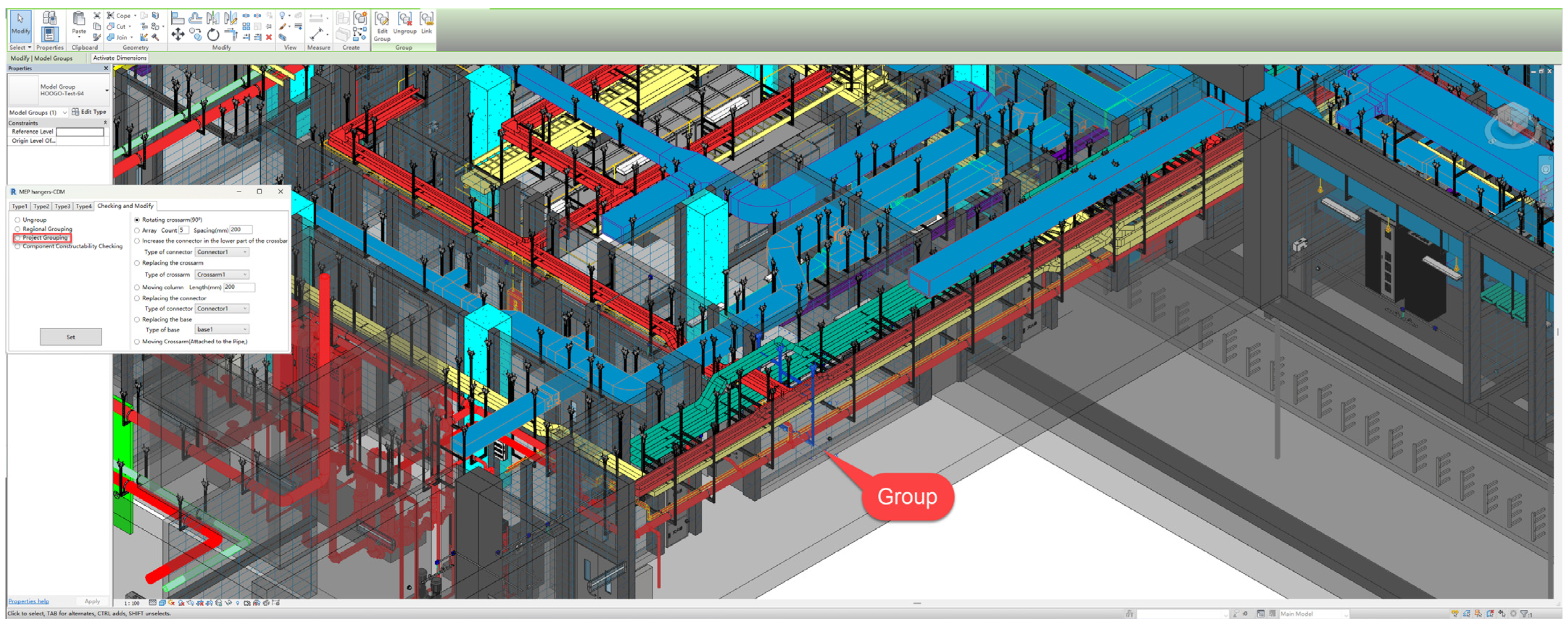
3.4. Automatic Grouping of Hanger Components and Component Constructability Checking

The extraction of model information can be only conducted when BIM models are sufficiently complete. The components are distributed independently in Revit; meanwhile, the components are not related to each other, which is believed to be a challenge for information extraction. Manual grouping tends to be less efficient and error-prone. Therefore, automatic grouping could make it more effective to integrate model information.
Whereas the traditional 2D designs can only add textual information to the geometry and their layers, an object-oriented modeling approach could be achieved by applying BIM. Thus, the components of the BIM models with a variety of properties make it possible to conduct constructability checking.
The information extracted from the BIM model is used to support the production and assembly of the MEP hanger. The evaluation of the connection relationship of the components in the MEP hanger group is the key to ensure the integrity and rationality of the MEP hanger. In Revit, components in a group have specific connections to each other.
For instance, the component connected to the base is a column. For the model generated by using modeling method 3, the components should contain one cross-arm and one column. The components connected to the column are cross-arms, base and connectors, and the quantity of base is one. The components connected to the cross-arm are columns and connectors, and the quantity of columns and connectors is two or multiples of two. The components connected to the connector are one crossbar and one column. If the collision inspection results include MEP components (Duct, Cable Tray, Pipe), it means that the current connection arrangement could not meet the construction requirements and a modification of the model is needed.
The process of extracting components before automatic grouping is an essential step. In Revit, the majority of objects that are visible to users are family instances. In this study, the elements to be grouped are obtained through ElementFilters. After the necessary elements were obtained, the specific operation process of Automatic Grouping of Hanger Components and Component Constructability Checking is divided into eight steps, as shown in Figure 10.
Step 1. Storing all objects (Family Instance) in list A (List<Family Instance>). Declare the variable S (Family Instance), which stores the object used for collision checking. Declare Boolean variable b. Declare lists R1 (List<Family Instance>) and R2 (List<Family Instance>). List R1 stores the components to be grouped, and list R2 stores the return values of collision checking of the variable S.
Step 2. If list A is null, the program ends. If list A is not null, take any element of list A and assign it to variable S. Variable b is assigned true. This algorithm takes the first element of list A which is equivalent to taking any element.
Step 3. Storing variable S in list R1.
Step 4. Performing a collision checking on variable S and storing the return values in list R2. Performing a specific checking logic based on the judgment. If the check does not pass, assign false to variable S.
Step 5. Removing elements in list R2 that do not belong to MEP hangers. Comparing list R1 and list R2 and deleting the elements in list R2 that are duplicated of list R1. If there are duplicate elements in list R2, delete additional duplicates of them.
Step 6. If list R2 is not null, assign any element in list R2 to variable S and return to step 3.
Step 7. If list R2 is null and variable b is true, the elements in list R1 are grouped. If list R2 is null and variable b is false, group the elements in list R1 and set the group name to Error.
Step 8. Compare list A and list R1, and remove the elements in list A that are duplicated of list R1. Clear list R1 and return to step 2.

4. Case Studies

Three case studies were conducted to validate the MEP hanger-CDM system based on the BIM platform. A MEP and architectural model of a subway station conforming to the codes was created by Revit. The basic information of the case project is illustrated in Table 1.
The MEP and architectural model of the subway station on Revit platform is shown in Figure 11. The MEP hanger-CDM is used to establish the hanger model in order to implement Automatic Grouping and Component Constructability Checking. Modification of models that failed the check was performed using the Modify system of MEP hanger-CDM.

4.1. Case Study: Quick Placement of MEP Hanger Components

Click the “CDM” icon on the tab to access the user interface of the MEP hanger-CDM System. The sub-tabs of the window are clearly visible with five tabs: Type1, Type2, Type3, Type4, and Checking and Modify, as shown in Figure 12. A new MEP hanger project could be conducted without creating instance family files in Revit. The files could be loaded automatically in the CDM system by clicking the “Load Families” button.
As shown in Figure 13, the section view for creating instances is obtained from the view of the 3D view and the 2D plan view. By selecting the different modeling types mentioned in Section 3.1, the model can be customized in the Section view by setting parameters and selecting component types.

4.2. Case Study: Automatic Grouping and Component Constructability Checking

After the MEP hanger individuals are quickly placed, there exist a large number of independent components in the Revit. As shown in Figure 14, the purpose of checking and modifying system functionality is to solve the cumbersome operational problem. “Region Grouping” is used for grouping in sub-regions, which brings convenience to collaborative design. “Project Grouping” is used for grouping all components in the project. “Component Constructability Checking” is used to check the connection relationship of components. The automatic grouping could be completed by selecting “Project grouping” and clicking the “Set” button to execute the algorithm mentioned in Section 3.4.
As shown in Figure 15, select “Component Constructability Checking” and click on the “Set” button, then the system will execute the algorithm mentioned in Section 3.4 to complete the constructability check. The check results are presented as comments on the plane view. The groups that passed the check were marked with “prefix” + “serial number” at the group’s position to facilitate the user to locate the installation location. The groups that failed to pass the check were marked with “ERROR” at the position of the group.

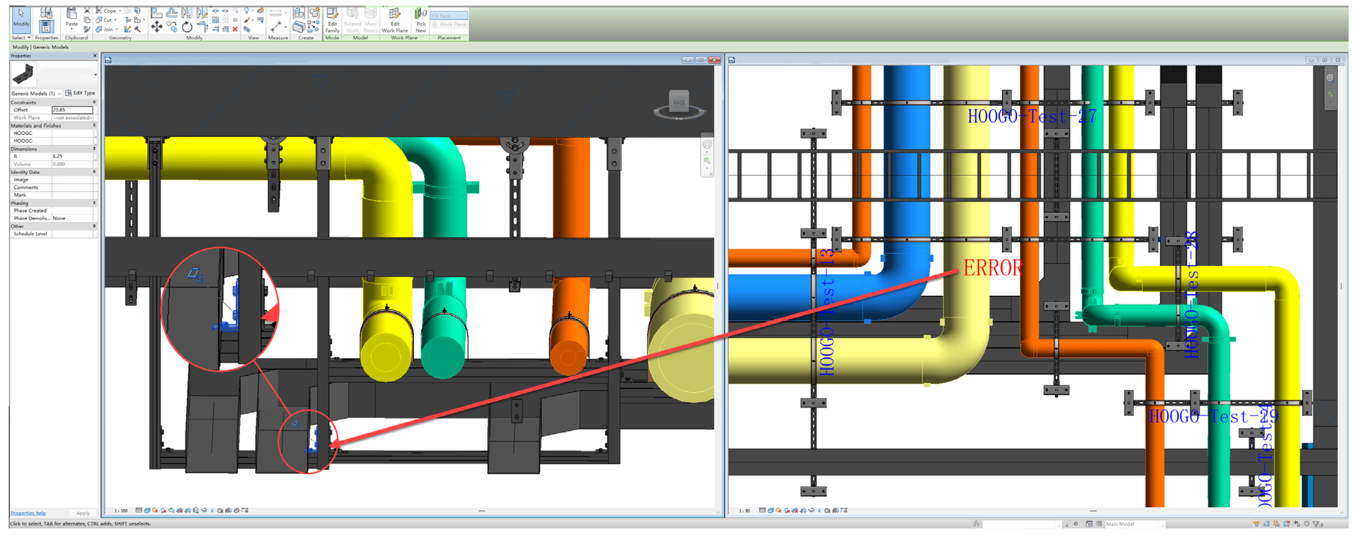
4.3. Case Study: Quickly Locate the Problem and Modify

Figure 16 illustrates the implementation process of the Modify system. The view will automatically aggregate the model groups that failed to pass the check, which could make it possible for users to locate and modify quickly.
Functions such as replace, move and rotate, etc., in the system could improve the efficiency of modifying models. Taking the collision error between the connector and cable tray in Figure 16 as an example, the model modification could be achieved by rotating the cross-arms or moving the columns.

4.4. Work Time Measurement

The performance of the plug-in was evaluated by comparing the design time of MEP hanger-CDM and conventional design methods. A series of results could be obtained by comparing the performance of the developed system with the existing work process in the phase of construction shop design model as shown in Table 2. During the design phase, the manpower number and work time decreased by 70% and 85.9%, respectively, with the involvement of the MEP hanger-CDM system, which is shown in Table 3. In the statistics, the number of workers and working time were not counted since the MEP hanger-CDM system was not involved in the creation of the MEP BIM model. In addition, the material lists and shop drawings are output manually by the Revit software function.

5. Discussion and Limitation

5.1. Discussion of Results

This study implemented a localized BIM application for the construction shop design of MEP hangers. Based on engineering practice needs and Revit secondary development technology, a MEP-CDM system was established to assist users in making decisions in the process of the construction shop design model of the MEP hanger. Three cases were examined to verify the effectiveness of the system.
In comparison to previous studies, the results of this study indicate that traditional design methods could not meet the design requirements of the construction shop design model of the MEP hanger, especially in complex MEP systems. Specifically, it is difficult for designers to establish hanger models through the Revit’s original functions. Therefore, a rapid modeling method is proposed and established in this study.
Various forms of MEP hangers were analyzed to identify the basic forms of MEP hanger layout by investigating the local construction companies and construction sites in China (described in Section 3.1). The MEP hanger model for LOD 400 could be automatically generated based on the connection relations of the MEP hanger components by using the localization criteria of the component families. Based on the basic form of MEP hanger, the modeling methods applicable to Revit were summarized to realize the quick placement of MEP hanger components. In addition, other families that satisfy the different localized design standard (described in Section 3.2) can be used by the Quick Placement system (described in Section 3.3).
It is relevant to note that this study not only realizes the rapid placement of hanger models, but also establishes an Automatic Grouping system and Component Constructability Checking system (described in Section 3.4) in combination with the ElementFilters method in the Revit API and the model space relationship in order to meet the engineering practice needs. Furthermore, checking logic in the Constructability Checking system can be added or removed according to the engineering practice checking requirements.
This study has been extensively utilized in practice, including in subway stations, parking lots and underground markets, to support several contractors and MEP projects in construction in China. The user-friendliness of the system and the return on investment have been proven to be positive through the usability feedback that was given by users.

5.2. Limitations

However, there are several limitations to this study. Compared to actual project requirements, the capabilities of this study are not yet sufficient to quick place uncommon forms of MEP hangers. For instance, steel-beam-based MEP hangers, which account for 15% of the project, cannot be applied to the Quick Placement system.
In addition, the shop drawings, material lists and calculation sheets that are generated in this study could only be achieved by the manual processes based on Revit’s original functions. Thus, a better version of the system with complete and efficient tools is needed to serve the project lifecycle. In the future, the developments of a BIM-based system require a wider range of domain expertise, which could be arduous and time-consuming.
Finally, the MEP hanger shop model created in this study is based on the section view with certain limitations in the user’s operation process, which makes the user unable to perform modeling operations in the 3D view. Possible solutions could be provided by recent studies of information and applied mathematics technologies, such as deep learning [37] and graph theory [38].

6. Conclusions

In this study, an automatic generation method of the construction shop design model system for MEP hanger was proposed. In addition, a plug-in for the automatic generation of the MEP hanger model was developed by using the Revit API. After the MEP hanger model is automatically generated by the plug-in, the model in 3D view could be observed and modified. Furthermore, the installation location of the MEP hanger in 2D plan view could be obtained at the same time. It could be concluded that the visualization of the MEP hanger engineering could provide a reference for the follow-up construction operations and maintenance. In practice, the results of the case study indicate a 70% reduction in the manpower number; meanwhile, the working time was shortened by 85.9%. The quality of MEP Hanger construction model design work could be improved by utilizing the results of this study. The speed, accuracy and convenience of creating, checking and modifying the work of MEP hanger can be achieved. As the quality of design work improves, it is possible to form judgments about items directly based on accurate 3D models rather than on experience. Therefore, inspections could be performed in advance to improve the constructability and quality of MEP hangers. At the same time, the informationalized construction shop design could be promoted, and provides potential values for the promotion and application of BIM technology in China.
The future work may focus on the following aspects:
  • BIM Forward Design: BIM Forward Design emphasizes that all project participants use one BIM model during the project process, with key technologies, including rapid modeling, model calculation, model modification, and automatic drafting [39,40]. However, research on BIM Forward Design still has a long way to go due to the complex structure of the participants in the design process.
  • BIM + blockchain: The core of Level 3 BIM is to emphasize that all construction participants work in a unified and shared model to facilitate deeper collaboration [41]. As one of the key technologies of Level 3 BIM, the combination of blockchain technology and BIM technology enables all parties involved in the project to easily contribute to the BIM model. Through blockchain technology, the project management process could be effectively recorded, and smart contracts could be executed between all parties involved in the project. Each process of project design can be permanently and effectively recorded and can be queried at any time [42,43]. With the development of computer technology and Internet of Things technology, it can be predicted that, in the future, blockchain technology will have an increasing number of application scenarios in the construction industry and will be widely applied in engineering practice.
  • Development of BIM standards: The foundation of BIM Forward Design and blockchain technology implementation is to obtain objects in the BIM model and combine them with specific algorithms. Therefore, only the standardization of the model objects can effectively integrate BIM with emerging technologies, and only the active support of project participants can effectively establish BIM standards. New challenges have been proposed for the development of BIM standards.

Author Contributions

Conceptualization, J.H.; Data curation, T.Z. and K.L.; Formal analysis, Q.B., X.F. and K.L.; Investigation, J.H., Q.B. and K.L.; Methodology, J.H.; Project administration, J.H.; Resources, J.H. and Q.B.; Software, J.H., T.Z. and J.Z.; Supervision, Q.B.; Validation, Q.B. and X.F.; Visualization, J.H., Q.B. and L.S.; Writing—original draft, J.H. and Q.B.; Writing—review and editing, J.H., T.Z., K.L. and L.S. All authors have read and agreed to the published version of the manuscript.

Funding

This work was supported by the National Natural Science Foundation of China (Grant number 72171224), and The Humanities and Social Sciences Foundation of China’s Education Ministry (Grant number 19YJAZH122).

Institutional Review Board Statement

Not applicable.

Informed Consent Statement

Not applicable.

Data Availability Statement

Not applicable.

Acknowledgments

The authors thank the following supporting the research: The Third Construction Co., Ltd. of China Construction Eighth Engineering Division, China University of Mining and Technology, Suzhou Hoogo Construction Buxiliary Co., Ltd. We would also like to thank the editors and reviewers for their valuable suggestions.

Conflicts of Interest

The authors declare no conflict of interest.

References

  1. Xie, X.; Zhou, J.; Fu, X.; Zhang, R.; Zhu, H.; Bao, Q. Automated Rule Checking for MEP Systems Based on BIM and KBMS. Buildings 2022, 12, 934. [Google Scholar] [CrossRef]
  2. Li, X.; Yang, D.; Yuan, J.; Donkers, A.; Liu, X. BIM-enabled semantic web for automated safety checks in subway construction. Autom. Constr. 2022, 141, 104454. [Google Scholar] [CrossRef]
  3. Hu, Z.; Zhang, J.; Yu, F.; Tian, P.; Xiang, X. Construction and facility management of large MEP projects using a multi-Scale building information model. Adv. Eng. Softw. 2016, 100, 215–230. [Google Scholar] [CrossRef]
  4. Wang, Y.; Zhang, L.; Yu, H.; Tiong, R.L.K. Detecting logical relationships in mechanical, electrical, and plumbing (MEP) systems with BIM using graph matching. Adv. Eng. Inform. 2022, 54, 101770. [Google Scholar] [CrossRef]
  5. Teo, Y.H.; Yap, J.H.; An, H.; Yu, S.C.M.; Zhang, L.; Chang, J.; Cheong, K.H. Enhancing the MEP Coordination Process with BIM Technology and Management Strategies. Sensors 2022, 22, 4936. [Google Scholar] [CrossRef]
  6. Zhao, Y.; Deng, X.; Lai, H. Reconstructing BIM from 2D structural drawings for existing buildings. Autom. Constr. 2021, 128, 103750. [Google Scholar] [CrossRef]
  7. Yarmohammadi, S.; Castro-Lacouture, D. Automated performance measurement for 3D building modeling decisions. Autom. Constr. 2018, 93, 91–111. [Google Scholar] [CrossRef]
  8. Rezaei, F.; Bulle, C.; Lesage, P. Integrating building information modeling and life cycle assessment in the early and detailed building design stages. Build. Environ. 2019, 153, 158–167. [Google Scholar] [CrossRef] [Green Version]
  9. Habib, U.E.H.; Nasir, A.R.; Ullah, F.; Qayyum, S.; Thaheem, M.J. BIM Roles and Responsibilities in Developing Countries: A Dedicated Matrix for Design-Bid-Build Projects. Buildings 2022, 12, 1752. [Google Scholar] [CrossRef]
  10. Oti, A.H.; Tizani, W. BIM extension for the sustainability appraisal of conceptual steel design. Adv. Eng. Inform. 2015, 29, 28–46. [Google Scholar] [CrossRef]
  11. Jung, Y.; Joo, M. Building information modelling (BIM) framework for practical implementation. Autom. Constr. 2011, 20, 126–133. [Google Scholar] [CrossRef]
  12. Vignali, V.; Acerra, E.M.; Lantieri, C.; Di Vincenzo, F.; Piacentini, G.; Pancaldi, S. Building information Modelling (BIM) application for an existing road infrastructure. Autom. Constr. 2021, 128, 103752. [Google Scholar] [CrossRef]
  13. Xie, M.; Qiu, Y.; Liang, Y.; Zhou, Y.; Liu, Z.; Zhang, G. Policies, applications, barriers and future trends of building information modeling technology for building sustainability and informatization in China. Energy Rep. 2022, 8, 7107–7126. [Google Scholar] [CrossRef]
  14. Bao, Q.; Zhou, J.; Zhao, Y.; Li, X.; Tao, S.; Duan, P. Developing A Rule-Based Dynamic Safety Checking Method for Enhancing Construction Safety. Sustainability 2022, 14, 14130. [Google Scholar] [CrossRef]
  15. Liu, J.; Cao, Y.; Xue, Y.; Li, D.; Feng, L.; Chen, Y.F. Automatic unit layout of masonry structure using memetic algorithm and building information modeling. Autom. Constr. 2021, 130, 103858. [Google Scholar] [CrossRef]
  16. Wang, J.; Lu, W. A deployment framework for BIM localization. Eng. Constr. Archit. Manag. 2022, 29, 407–430. [Google Scholar] [CrossRef]
  17. Succar, B. Building information modelling framework: A research and delivery foundation for industry stakeholders. Autom. Constr. 2009, 18, 357–375. [Google Scholar] [CrossRef]
  18. Sampaio, A.Z. Project management in office: BIM implementation. Procedia Comput. Sci. 2022, 196, 840–847. [Google Scholar] [CrossRef]
  19. Zhao, X. A scientometric review of global BIM research: Analysis and visualization. Autom. Constr. 2017, 80, 37–47. [Google Scholar] [CrossRef]
  20. Alreshidi, E.; Mourshed, M.; Rezgui, Y. Factors for effective BIM governance. J. Build. Eng. 2017, 10, 89–101. [Google Scholar] [CrossRef] [Green Version]
  21. Cheng, J.C.P.; Lu, Q.; Deng, Y. Analytical review and evaluation of civil information modeling. Autom. Constr. 2016, 67, 31–47. [Google Scholar] [CrossRef]
  22. Condotta, M.; Scanagatta, C. BIM-based method to inform operation and maintenance phases through a simplified procedure. J. Build. Eng. 2023, 65, 105730. [Google Scholar] [CrossRef]
  23. Khahro, S.H.; Kumar, D.; Siddiqui, F.H.; Ali, T.H.; Raza, M.S.; Khoso, A.R. Optimizing Energy Use, Cost and Carbon Emission through Building Information Modelling and a Sustainability Approach: A Case-Study of a Hospital Building. Sustainability 2021, 13, 3675. [Google Scholar] [CrossRef]
  24. Yilmaz, G.; Akcamete, A.; Demirors, O. BIM-CAREM: Assessing the BIM capabilities of design, construction and facilities management processes in the construction industry. Comput. Ind. 2023, 147, 103861. [Google Scholar] [CrossRef]
  25. Liu, J.; Shi, G. Quality Control of a Complex Lean Construction Project Based on KanBIM Technology. EURASIA J. Math. Sci. Technol. Educ. 2017, 13, 5905–5919. [Google Scholar] [CrossRef]
  26. Leite, F.; Akcamete, A.; Akinci, B.; Atasoy, G.; Kiziltas, S. Analysis of modeling effort and impact of different levels of detail in building information models. Autom. Constr. 2011, 20, 601–609. [Google Scholar] [CrossRef]
  27. Liu, Y.; van Nederveen, S.; Hertogh, M. Understanding effects of BIM on collaborative design and construction: An empirical study in China. Int. J. Proj. Manag. 2017, 35, 686–698. [Google Scholar] [CrossRef]
  28. Ahmad, T.; Thaheem, M.J. Developing a residential building-related social sustainability assessment framework and its implications for BIM. Sustain. Cities Soc. 2017, 28, 1–15. [Google Scholar] [CrossRef]
  29. Kim, J.; Fischer, M.; Kunz, J.; Levitt, R. Sharing of Temporary Structures: Formalization and Planning Application. Autom. Constr. 2014, 43, 187–194. [Google Scholar] [CrossRef]
  30. Lee, B.; Choi, H.; Min, B.; Ryu, J.; Lee, D. Development of formwork automation design software for improving construction productivity. Autom. Constr. 2021, 126, 103680. [Google Scholar] [CrossRef]
  31. Xie, H.; Tramel, J.M.; Shi, W. Building Information Modeling and simulation for the mechanical, electrical, and plumbing systems. In Proceedings of the 2011 IEEE International Conference on Computer Science and Automation Engineering, Shanghai, China, 10–12 June 2011; pp. 77–80. [Google Scholar]
  32. Liu, H.; Singh, G.; Lu, M.; Bouferguene, A.; Al-Hussein, M. BIM-based automated design and planning for boarding of light-frame residential buildings. Autom. Constr. 2018, 89, 235–249. [Google Scholar] [CrossRef]
  33. El-Diraby, T.; Krijnen, T.; Papagelis, M. BIM-based collaborative design and socio-technical analytics of green buildings. Autom. Constr. 2017, 82, 59–74. [Google Scholar] [CrossRef]
  34. Wang, D.; Hu, Y. Research on the Intelligent Construction of the Rebar Project Based on BIM. Appl. Sci. 2022, 12, 5596. [Google Scholar] [CrossRef]
  35. Wang, J.; Wang, X.; Shou, W.; Chong, H.; Guo, J. Building information modeling-based integration of MEP layout designs and constructability. Autom. Constr. 2016, 61, 134–146. [Google Scholar] [CrossRef]
  36. Chen, S.; Zeng, Y.; Majdi, A.; Salameh, A.A.; Alkhalifah, T.; Alturise, F.; Ali, H.E. Potential features of building information modelling for application of project management knowledge areas as advances modeling tools. Adv. Eng. Softw. 2023, 176, 103372. [Google Scholar] [CrossRef]
  37. Hong, Y.; Park, S.; Kim, H.; Kim, H. Synthetic data generation using building information models. Autom. Constr. 2021, 130, 103871. [Google Scholar] [CrossRef]
  38. Gan, V.J.L. BIM-based graph data model for automatic generative design of modular buildings. Autom. Constr. 2022, 134, 104062. [Google Scholar] [CrossRef]
  39. Yuan, Y.; Yuan, J. The theory and framework of integration design of building consumption efficiency based on BIM. Procedia Eng. 2011, 15, 5323–5327. [Google Scholar] [CrossRef] [Green Version]
  40. Sydora, C.; Stroulia, E. Rule-based compliance checking and generative design for building interiors using BIM. Autom. Constr. 2020, 120, 103368. [Google Scholar] [CrossRef]
  41. Seidenschnur, M.; Kücükavci, A.; Fjerbæk, E.V.; Smith, K.M.; Pauwels, P.; Hviid, C.A. A common data environment for HVAC design and engineering. Autom. Constr. 2022, 142, 104500. [Google Scholar] [CrossRef]
  42. Mahmudnia, D.; Arashpour, M.; Yang, R. Blockchain in construction management: Applications, advantages and limitations. Autom. Constr. 2022, 140, 104379. [Google Scholar] [CrossRef]
  43. Nawari, N.O.; Ravindran, S. Blockchain and the built environment: Potentials and limitations. J. Build. Eng. 2019, 25, 100832. [Google Scholar] [CrossRef]
Figure 2. MEP hanger basic forms.
Buildings 13 00867 g002
Figure 3. Schematic diagram of the four modeling types in the section view.
Buildings 13 00867 g003
Figure 4. Relationships between the component features and the design standards of families.
Buildings 13 00867 g004
Figure 5. Family models of hanger components.
Buildings 13 00867 g005
Figure 6. The framework of quick placement system.
Buildings 13 00867 g006
Figure 7. Schematic diagram of the calculation process of coordinates of the bases.
Buildings 13 00867 g007
Figure 8. Schematic diagram of the calculation process of coordinates and length of the columns.
Buildings 13 00867 g008
Figure 9. Schematic diagram of the calculation of the cross-bar coordinates and length.
Buildings 13 00867 g009
Figure 10. Algorithm for Automatic Grouping and Component Relationship Checking.
Buildings 13 00867 g010
Figure 11. The BIM model and the CDM tab.
Buildings 13 00867 g011
Figure 12. The user interface of the MEP hanger-CDM System.
Buildings 13 00867 g012
Figure 13. Usage of the quick placement system.
Buildings 13 00867 g013
Figure 14. The result of the Automatic Grouping.
Buildings 13 00867 g014
Figure 15. The result of the Component Constructability Checking.
Buildings 13 00867 g015
Figure 16. The user interface of the Checking and Modify.
Buildings 13 00867 g016
Table 1. Case project overview.
CategoryDetailed Contents
ProjectA subway station in Suzhou
Gross floor area23,261 m2
FloorsBelow the ground: 2
Evaluation subjectMEP hangers of a subway station
Table 2. Results of the individual steps of model construction.
Step of Model ConstructionAims/TargetsFunctionsResults
Step 1Loading Family FilesAutomatically loading family files for new BIM modelsReduce working hours
Step 2Placement of hangers componentsConvenient placement of componentsEnhance design efficiency and visualization
Step 3Model groupingAutomatic groupingReduce operational errors and working hours
Step 4Model checkingAutomatic checkingReduce working hours and improve the accuracy of checking
Step 5Model ModificationModify a BIM model in 3D ViewEnhance the constructability of the hanger models
Step 6Material list and construction shop drawingsRevit’s original functionsData output by Revit meets construction requirements
Table 3. Time measurement results of the work process.
CategoryExisting Work ProcessMEP Hanger-CDM Work Process
Number of workers103
MEP BIM Model creating    
    
Loading family files10m10s
Placement of hanger components9d2d
Model grouping1d12m
Model checking3d26m
Model modification5d0.5d
Material list and construction shop drawings    
    
Total time taken18d 10m2.5d 38m 10s
Disclaimer/Publisher’s Note: The statements, opinions and data contained in all publications are solely those of the individual author(s) and contributor(s) and not of MDPI and/or the editor(s). MDPI and/or the editor(s) disclaim responsibility for any injury to people or property resulting from any ideas, methods, instructions or products referred to in the content.

